EP2919583B1 - Insect trap having an air-actuated damper - Google Patents
Insect trap having an air-actuated damper Download PDFInfo
- Publication number
- EP2919583B1 EP2919583B1 EP13854502.5A EP13854502A EP2919583B1 EP 2919583 B1 EP2919583 B1 EP 2919583B1 EP 13854502 A EP13854502 A EP 13854502A EP 2919583 B1 EP2919583 B1 EP 2919583B1
- Authority
- EP
- European Patent Office
- Prior art keywords
- damper
- housing body
- housing
- insect trap
- trap
- Prior art date
- Legal status (The legal status is an assumption and is not a legal conclusion. Google has not performed a legal analysis and makes no representation as to the accuracy of the status listed.)
- Active
Links
Images




Classifications
-
- A—HUMAN NECESSITIES
- A01—AGRICULTURE; FORESTRY; ANIMAL HUSBANDRY; HUNTING; TRAPPING; FISHING
- A01M—CATCHING, TRAPPING OR SCARING OF ANIMALS; APPARATUS FOR THE DESTRUCTION OF NOXIOUS ANIMALS OR NOXIOUS PLANTS
- A01M1/00—Stationary means for catching or killing insects
- A01M1/02—Stationary means for catching or killing insects with devices or substances, e.g. food, pheronones attracting the insects
- A01M1/023—Attracting insects by the simulation of a living being, i.e. emission of carbon dioxide, heat, sound waves or vibrations
-
- A—HUMAN NECESSITIES
- A01—AGRICULTURE; FORESTRY; ANIMAL HUSBANDRY; HUNTING; TRAPPING; FISHING
- A01M—CATCHING, TRAPPING OR SCARING OF ANIMALS; APPARATUS FOR THE DESTRUCTION OF NOXIOUS ANIMALS OR NOXIOUS PLANTS
- A01M1/00—Stationary means for catching or killing insects
- A01M1/08—Attracting and catching insects by using combined illumination or colours and suction effects
Definitions
- This invention relates to an apparatus for trapping insects.
- it relates to an insect trap which utilizes multiple attractants and a unique air-actuated two-piece damper that traps insects within the confines of the trap.
- Suction-type insect traps utilize a suction mechanism, such as a fan disposed in a chamber, to draw or blow air into the trap and capture any insects that are caught in the flow of air associated with operation of the fan. Then, the captured insects must usually be retained or housed in a closed space to prevent escape of insects from the trap.
- An attractant may be used to lure insects to the air flow. Without such an attractant, only those insects that are exposed to the air flow via happenstance can commonly be captured.
- the prior art teaches the use of a variety of attractants, such as heat, water vapor, or carbon dioxide, to lure insects into the vicinity of a trap.
- attractants such as heat, water vapor, or carbon dioxide
- These attractants simulate the elements that are found in the breath and sweat of warm-blooded mammals, the target of many biting and/or blood-sucking insects. Many insects are also attracted to light and will gather around light sources.
- the effectiveness of such insect traps depends largely on the combined effectiveness of the attractant, the suction or air flow mechanism, and the insect retaining cage.
- Carbon dioxide has been known to be used as an attractant, methods of carbon dioxide dispersion have been less commercially viable. Carbon dioxide gas used as an attractant is typically provided by pressurized tanks or by the sublimation of dry ice. While these methods supply carbon dioxide, they have not been commercially viable options since they are heavy and occupy a lot of space.
- An effective trap may involve a quiet yet powerful fan, but the trap must also be constructed so that insects are not able to escape once they are trapped within the confines of the trap. In particular, it is desirable for the insects to not escape when the fan is powered off and there is no longer any suction mechanism in effect within the trap.
- the prior device includes a device for trapping live flying insects, such as mosquitoes including an electric light reflected by a parabolic reflector horizontally in all directions to attract the mosquitoes, and electric fan to blow the mosquitoes downwardly into a collection bag, and a valve between the fan and the collection bag which is biased to close the entrance to the collection bag when the fan is not operating and to be opened by the force of air from the fan when it is operating.
- live flying insects such as mosquitoes including an electric light reflected by a parabolic reflector horizontally in all directions to attract the mosquitoes, and electric fan to blow the mosquitoes downwardly into a collection bag
- a valve between the fan and the collection bag which is biased to close the entrance to the collection bag when the fan is not operating and to be opened by the force of air from the fan when it is operating.
- a three-way protection system involves: (1) one or more insect attractants; (2) an effective fan mechanism to overpower insects and direct them toward the trap; and (3) a secure retention mechanism that prevents escape of captured insects.
- the trap utilizes an air-actuated two-piece damper assembly which prevents insects from escaping the trap when the fan is turned off and when there is no air flow through the trap, but also allows insects to enter the retaining cage when the fan is turned on and when there is air flow through the trap.
- an insect trap that does not use pesticides or emit otherwise harmful chemicals into the environment.
- an insect trap that utilizes a suction vacuum in conjunction with multiple non-chemical attractants. This provides an environmentally friendly and odor-free solution to eliminate unwanted insects without being unduly obtrusion to the enjoyment of people who may be nearby.
- an insect trap that ensnares the insects when the suction vacuum is turned off so that insects cannot escape. By doing so, the user is able to clean the trap or simply let the trap sit unpowered without insects escaping.
- an air-actuated damper which self-closes when the fan is off but provides adequate access to the insect cage during operation of the fan.
- an insect trap that is lightweight, easy to install, and convenient to use.
- a trap that is made of durable yet lightweight materials (e.g., plastic or metal) that can be easily carried by the user and then placed or hung in an indoor or outdoor environment.
- the trap is also preferably constructed and packaged so that it does not require assembly by the user.
- an insect trap may be suitable for indoor use, outdoor use, or both, and may not be limited by a single designation.
- the insect trap is used for outdoor use and provides protection of the operating components of the trap assembly from the natural elements.
- the outdoor-use insect trap comprises three main housing elements: a roof, a body, and a retaining cage. It is contemplated that the trap may be defined by other main housing elements.
- the outdoor-use insect trap has a rain roof which provides protection for the majority of the trap assembly from the natural elements, such as rain.
- the rain roof is attached to the body and may be removable or fixed.
- the attachment means for the rain roof may be vertical rods which suspend the roof above the body, or a securing mechanism that attaches the rain roof directly to the body.
- the rain roof is shaped to overlap the body and allow rain to run past the roof and fall past the body to prevent moisture from entering the interior of body.
- the rain roof may be constructed of a durable plastic or metal material.
- the rain roof or cover may have a transparent or translucent inlet or be constructed of a transparent or translucent material to allow light rays to emit beyond the trap assembly and attract insects.
- the insect trap has a solar cell roof that utilizes the sun's rays to power the trap.
- the solar cell roof has a plurality of photovoltaic cells which converts the energy of light into electricity through a photovoltaic effect. This electricity is used to power, e.g., a light source and fan.
- the insect trap may be used indoors, and thus, the housing construction may differ.
- the rain roof serves simply as a cover and does not necessarily protect the body from the natural elements or may be wholly removed. It may not overlap the body, but instead, may be constructed to be flush with the body to provide a smooth contour.
- the roof or cover serves as an attachment means for a light source, and the interior of the roof or cover may contain an electrical assembly to activate such light source. It is contemplated that the electrical assembly may be external to the insect trap or located in the trap body.
- the electrical assembly is connected to a power source, e.g., solar cell, A.C. power supply, or battery.
- the roof or cover may provide an attachment means for a hook or handle so that the user can easily carry and transport the trap.
- the roof has a suspension ring to allow the insect trap to be hung.
- the roof has a handle to allow the user to easily pick up and carry the trap.
- the insect trap has a body which is generally cylindrical in shape and has several elements located within the interior of the body.
- one or more screens, a fan assembly, and a damper are located within the confines of the body.
- the body is constructed so that a vacuum air-flow is created by the fan assembly and the cylindrically shaped body. It is contemplated that other operational features may be located within the body.
- insects may enter the interior of the body.
- the roof or cover is attached to the body by a plurality of stiff vertical rods, and insects enter the trap through the space between the rods.
- the roof or cover is coupled to the body through a screw mechanism or other attachment means directly onto the body. The upper area of the body may then have vertical slots removed from the housing walls through which insects may enter the interior. These openings not only allow insects to enter the interior but also allow the light source to emit light rays to the outside of the trap.
- the upper portion of the body contains a first protective screen.
- the protective screen is disposed horizontally and covers the orifice of the body. It contains a plurality of air passages to allow insects and air to pass through. However, the slots are preferably small enough to prevent foreign objects (aside from insects) from contacting the fan.
- the protective screen may be constructed of a durable plastic or metal material.
- the middle portion of the body contains a quiet yet powerful fan that draws insects into the body and down into the retaining cage.
- the fan is attached to the inner sidewall by an attachment means and is powered by a power source, e.g., solar cell, A.C. power supply, or battery.
- a power source e.g., solar cell, A.C. power supply, or battery.
- the trap assembly could include a power source or be configured to receive power from an external source. Regardless of the source of the operating power, the fan blades may preferably rotate in a horizontal direction.
- the fan may be constructed of a durable plastic or metal material.
- a second screen is located within the lower portion of the body.
- the screen is disposed horizontally and is located below the fan assembly. It contains a plurality of air passages to allow insects and air to pass through the screen.
- the screen may be constructed of a durable plastic or metal material.
- the retaining cage is removably attached to the bottom of the body and may lock in place.
- the cage may be cylindrical in shape and comprises an open top portion and a closed bottom portion.
- the sidewalls of the cage may be lined with a mesh material as to allow airflow but prevent passage of insects through the sidewalls of the cage. Insects trapped in the cage eventually dehydrate and die.
- a damper feature prevents insects from escaping the trap when the fan is turned off or when there is no or only limited air flow through the trap.
- a damper assembly is located in the lower portion of the body or alternatively, in the upper portion of the retaining cage. The damper assembly prevents insects from escaping the trap when the fan is turned off or when there is insufficient air flow through the trap to open the damper - such as if the fan is damaged or otherwise rendered inoperable.
- the damper assembly is biased toward a closed position when the fan is off.
- the damper assembly is air-actuated so that it can achieve an open position when the fan is on.
- the damper assembly has two damper flaps that are each shaped as semi-circles, and when in a closed position, form a circle that obstructs a circular passage or opening between the housing and the cage. It is appreciated that the damper flaps may be any shape to obscure the shape of the opening.
- the damper flaps may be attached to the housing by pivot pins that are located on opposite sides of each flap's semi-circle arc although the flaps could alternatively be supported by the upper end of the cage. However, the pins may be located inward from the straight edge.
- each damper flap Located behind each damper flap is a stop-bar which provides support to the respective damper flap and prevents the respective flap from swinging to an over-center position with respect to the axis defined by the pivot and the center of gravity of the respective flap.
- the stop bar also limits translation of the respective flap from its intended location during transport of the trap.
- Each flap has a weighted rod located on the straight edge to create the appropriate weighted balance.
- the weighted rods may be constructed of a metal material.
- an on-off twist feature seals the unit openings when the fan is turned off so that insects are unable to escape. More particularly, a twist mechanism activates a covering which obscures the slot openings in the body.
- the sidewalls of the body are coated with titanium dioxide, a substance which undergoes a photocatalytic reaction when it comes into contact with UV light, and thereafter releases carbon dioxide and water vapor.
- the carbon dioxide and water vapor is disseminated by the fan and attracts insects to the trap.
- Other substances may be used to emit carbon dioxide.
- the insect trap may have a water tray, typically for outdoor use, coupled to the insect trap housing, which collects rain water in order to lure egg-laying insects to the vicinity of the trap.
- the water tray may or may not be removable.
- an indoor use trap is made to easily mount on a wall or lie flat on a table, countertop, or shelf.
- the housing is made of two parts that are coupled together to provide a smooth outer contour, and a back side that is made to mount flush with the wall.
- the upper portion contains a UV light source, a carbon dioxide releasing coating, and a fan.
- the upper portion has slotted openings to allow insects to enter the trap, and to allow light rays to escape.
- the lower portion contains a retaining cage which can be removed from the assembly to clean out the contents.
- the lower potion also has slotted openings to allow air flow through the bottom, however, the openings do not allow insects to escape. It is contemplated that the trap may also contain a damper assembly to trap insects within the trap.
- the insect trap can be used continually and can be used to catch a variety of insects, e.g., mosquitoes, biting flies, Asian beetles, wasps, hornets, yellow jackets, moths, stink bugs, and other flying insects. It is further contemplated that the insect trap assembly can be provided in a variety of colors to satisfy user preferences and can be configured to be hung from a pole stand, mounted to a wall, hung from a chain, or placed on the ground or on a table during operation.
- insects e.g., mosquitoes, biting flies, Asian beetles, wasps, hornets, yellow jackets, moths, stink bugs, and other flying insects.
- insect trap assembly can be provided in a variety of colors to satisfy user preferences and can be configured to be hung from a pole stand, mounted to a wall, hung from a chain, or placed on the ground or on a table during operation.
- Fig. 1 shows an insect trap assembly 10 according to the present invention.
- Insect trap assembly 10 includes a cover or a roof 12 that generally overlies a housing body or housing 14 and a trap or cage 16 that is removably connected to housing 14 and constructed to retain insects.
- Roof 12 includes an exterior surface 18 that is oriented to face an operating environment and an interior surface 20 that generally underlies exterior surface 18 and faces a top surface 22 of housing 14.
- Roof 12 includes a perimeter 24 that defines a footprint of roof 12. Although shown as generally circular, it is appreciated that perimeter 24 could have any shape.
- exterior surface 18 of roof 12 is bounded on its radial edges by perimeter 24 and includes a number of ridges, contours, or tiers 26 that extend in a gravitational direction relative to the intended orientation of roof 12 during use of trap assembly 10.
- exterior surface 18 of roof 12 could have a concave or toroidal shape with respect to perimeter 24 and a centerline, indicated by line 28, of assembly 10.
- Such a construction would allow roof 12 of trap assembly 10 to retain an amount of water, whether provided by a user or as rainfall, to attract insects to trap assembly 10.
- one aspect of the present invention is to provide a number of insect attractants so as to draw intended targets to the trapping device.
- Water is only one such attractant and can be provided by roof 12 of assembly 10, as explained above, and/or provided by other structures associated with housing 14 and/or cage 16,
- a number of posts 30 extend between interior surface 20 of roof 12 and top surface 22 of housing 14.
- Posts 30 are preferably spaced about a circumference associated with a radial perimeter 32 of top surface 22 of housing 14.
- Posts 30 define a gap 34 between interior surface 20 of roof 12 and top surface 22 of housing 14, As explained further below, gap 34 is shaped to allow insects to pass into the space between roof 12 and housing 14 and to be drawn and/or forced through the operational features of trap assembly 10. It is appreciated that although three posts 30 are shown, other numbers of posts may be provided to create the offset or gap 34 between roof 12 and housing 14.
- the roof 12 preferably contains a hanging ring 11 in the middle of its exterior surface 18 for hanging the trap 10 by a hook or other mounting apparatus. It is appreciated that there may be alternative ways to mount trap 10, such as by a pole stand or hung from a chain. It is also appreciated that the mounting means may be located at other areas of trap 10 besides the roof 12, such as on housing 14.
- the roof 12 optionally contains solar cell 86 for powering the various electrical components located in or on trap 10. It is appreciated that there may be a varying number of solar cells 86 and that they may be located anywhere on trap 10, such as on roof 12 or housing 14.
- the radial perimeter 32 of housing 14 receives posts 30 through corresponding receiving holes 36 spaced about a circumference associated with the radially positioning of posts 30.
- the posts 30 are fixed within holes 36 by an attachment means, such as bolts or screws 38, to prevent vertical movement of posts 30. It is contemplated that posts 30 may be fixed by other means, such as by welding or an adhesive.
- the posts 30 are extended downward into holes 36 to a depth that is able to receive an attachment means, such as screws 38.
- the radial perimeter 32 is constructed of a reinforced plastic to provide radial strength to housing 14 and support for the weight of the upper elements.
- the radial perimeter 32 may be a sleeve 41 with a cavity 40 to receive the upper perimeter 42 of the housing 14 within the cavity 40.
- the sleeve 41 is slid over the upper perimeter 42 to receive the edge of the upper perimeter 42.
- the sleeve 41 may be fixedly attached to the housing body by bolts or screws 38, or other attachment means.
- the radial perimeter 32 may alternatively be a piece that is attached parallel to the upper perimeter 42 by a fastening means, such as a bolt or screw.
- the radial perimeter 32 may be provided as either a piece separate from housing 14, or a reinforced edge on housing 14 itself
- housing 14 is shown to have a generally cylindrical shape, it is appreciated that housing 14 could have any shape.
- a screen or a first protective screen 46 is disposed across the top surface 22 of housing 14.
- First protective screen 46 includes an exposed top surface 49 that faces the interior surface 20 of the roof 12 and a bottom surface 53 that underlies the top surface 49 and faces inwardly into the interior 84 of housing 14.
- the protective screen 46 is grated to provide for a plurality of preferably small openings 48 that allow air flow and small insects to pass through screen 46, but do not allow larger foreign objects to pass there beyond.
- the protective screen 46 is coupled to the inner wall 50 of the housing 14 and suspended over the entire top surface 22 of housing 14.
- Insects attracted to the trap are drawn into the trap 10 through the gap 34 between posts 30 and enter the space between roof 12 and housing 14. Insects then enter the housing 14 by passing through the openings 48 of protective screen 46 and pass to the interior 84 of housing 14. The insects pass the operational features disposed in the interior 84 of housing 14 and exit the housing 14 by passing downward through a bottom base 52 of housing 14 and into the attached retaining cage 16.
- bottom base 52 of housing 14 has a generally cylindrical shape and corresponds to the shape of the housing 14 but widens in a concave manner to provide an expanding diameter orifice or opening 95. It is appreciated that bottom base 52 may be shaped in a number of ways and may not expand in diameter.
- the bottom base 52 is sized to overlap the upper perimeter 66 of retaining cage 16 to securely couple the housing 14 to the retaining cage 16.
- the bottom base 52 may also have a locking mechanism 54 consisting of locking holes 56 for receiving corresponding lock pieces 58 of the retaining cage 16.
- the retaining cage 16 is disposed below the housing 14 and fixably attached to capture insects exiting the bottom base 52 of housing 14. As insects exit bottom base 52, they are retained within the confines of cage 16.
- the cage 16 is a generally drum-shaped structure with an open top 60 and closed bottom 62. It is supported by a frame 64 that has an upper perimeter 66, lower perimeter 68 and connecting rods 70 that connect the upper 66 and lower 68 perimeters, The connecting rods 70 are preferably spaced about a circumference associated with a radial perimeter of cage 16.
- a mesh netting 72 is lined within the interior of the retaining cage 16 to cover the spaces 74 created between rods 70. The netting 72 prevents insects from escaping the retaining cage 16, visual inspection of the contents of the cage 16 by a user, and allows the air directed housing 14 to egress trap assembly 10.
- trap assembly 10 is configured for operation with a number of optional attractants.
- One such attractant is the generation of light rays.
- a light assembly 76 is coupled to the interior surface 20 of roof 12 by one or more mounting brackets 78.
- the interior surface 20 may attach mounting brackets 78 to receive the ends of one or more UV light bulbs 80 or other light sources. It is appreciated that there are alternative ways to mount light bulbs 80 within the interior surface 20 of roof 12, and that the light assembly may be mounted on different areas on the trap 10.
- the light assembly 76 is attached to a power source, such as an AV power supply, battery source, or solar powered cells.
- the power source may be located on or in trap 10 or externally provided.
- Another attractant contemplated is carbon dioxide or a carbon dioxide releasing substance 81.
- the inner wall 50 of the housing is coated with a substance 81, such as titanium dioxide, which releases carbon dioxide when exposed to UV light rays. It is appreciated that other carbon dioxide releasing substances may be used as attractants to draw insect into the trap's vicinity. It is also appreciated that the substance may be coated at various locations on the trap, such as on the interior surface 20 of roof 12 or on the exterior surface of housing 14 to name but a few.
- the water tray 136 may be removable or permanent and may be attached to the housing 14 via a number of methods, such as by screws or by being slidably fitted around the housing's 14 circumference.
- Insects that enter housing 14 by passing through the openings 48 of protective screen 46 pass through a number of operational features located in the interior 84 of housing 14.
- a fan assembly 82 which is fixably attached to the inner wall 50 of housing 14 by bolts 83, or the like, and suspended in the middle of the interior 84.
- the fan assembly 82 is attached to the inner wall 50 by a number of rigid suspension rods 88 that are bolted to inner wall 50 and attached to the bottom portion 85 of fan assembly 82.
- the suspension rods 88 are located so that they do not interfere with movement of blades 90 of the fan assembly 82.
- the fan assembly 82 has rotatable blades 90 that preferably rotate in a horizontal plane that is aligned between the first protective screen 46 and a second protective screen 91. It is contemplated that blades 90 may be provided at different pitches in order to create the desired air flow or vacuum effect. It is also contemplated that the fan assembly 82 may be located at different locations within the interior 84 of housing 14. That is fan assembly 82 need not be centrally located and/or can be disposed nearer one of screens 46, 91.
- Second protective screen 91 is disposed below fan assembly 82 and includes an upper surface 93 that faces inwardly toward the housing interior 84 and a bottom surface 92 that generally underlies upper surface 93 and faces a damper assembly 96.
- Protective screen 91 is grated to provide for a plurality of small openings 94 that allow air flow and small insects to pass through the openings 94.
- the protective screen 91 is coupled to the inner wall 50 of the housing 14 and is suspended over the entire bottom opening 95 of the housing 14. Screen 91 prevents unintended objects from inadvertently passing into housing 14 but is constructed to allow insects to pass fairly unobstructed therethrough.
- a damper assembly 96 is coupled to bottom base 52.
- Damper assembly 96 includes two damper flaps 98 that each independently rotate between open and closed positions.
- the damper flaps 98 are preferably semi-circular to collectively cover the circular opening 95.
- damper flaps 98 are in a closed position and cover the bottom opening 95 of the housing 14 to prevent insects from escaping retaining cage 16.
- damper flaps 98 are in an open position and provide a space 99 to allow insects to be passed into the retaining cage 16.
- the damper flaps 98 In an open position, the damper flaps 98 extend to a position that is preferably less than ninety degrees and extend outwardly into the attached retaining cage 16. Full extension of the damper flaps 98 is limited by stop-bars 100 which provide support and prohibit movement of the flaps 98.
- the bars 100 are attached to the inside wall 102 of bottom base 52 by pivot pins 104 that are attached inwardly from the straight edge 108 of flaps 98.
- weighted rods 1 06 which are preferably made of a metal material, to create a desired weighted balance of each flap 98.
- weighted rods 106 may be made of any weighted material. Regardless of the material they are constructed of, rods 106 are orientated relative to the respective flap 98 and pivot pins 104 to bias the respective flap toward the closed position.
- the damper flaps 98 align at their straight edges 108 to completely conceal the opening 95 and prevent insects from escaping the retaining cage 16.
- the weighted rods 106 at the straight edge 108 of the flaps 98 bias the flaps 98 toward a closed position when no air is flowing through the trap.
- the flap 98 when the damper flap 98 is in an open position, the flap 98 is rotated about pivot pin 104 to dispose flap 98 at an angle that is preferably less than ninety degrees relative to the closed position and less than center with respect to the axis defined by the pivot 104 and the center of gravity of the flap 98.
- the flap 98 is prevented from extending further by stop-bar 100 which is disposed directly behind flap 98 and is fixably attached to the inside wall 102 of bottom base 52.
- notch 110 located on stop-bar 100 abuts flap 98 to prevent further rotation. This disposition provides space 99 which allows insects to pass outwardly from the housing 14 and into the retaining cage 16.
- the locking mechanism 54 of the bottom base 52 to the retaining cage 16 consists of holes 56 at the bottom base which receive the corresponding lock pieces 58 of the top of the retaining cage 16.
- the lock pieces 58 are fitted with the holes 56.
- the user then rotates the bottom base 52 and retaining cage 16 in opposite directions to secure the locking pieces 58 within the holes 56. In a locked position, the lock pieces 58 are unable to slide out of holes 56.
- the user rotates the bottom base 52 and the retaining cage in opposite rotational directions as used to secure.
- the lock pieces 58 are then permitted to slide out of holes 56 and the retaining cage 16 can be removed from the bottom base 52 for cleaning, or the like.
Landscapes
- Life Sciences & Earth Sciences (AREA)
- Pest Control & Pesticides (AREA)
- Engineering & Computer Science (AREA)
- Insects & Arthropods (AREA)
- Wood Science & Technology (AREA)
- Zoology (AREA)
- Environmental Sciences (AREA)
- Catching Or Destruction (AREA)
Description
- This invention relates to an apparatus for trapping insects. In particular, it relates to an insect trap which utilizes multiple attractants and a unique air-actuated two-piece damper that traps insects within the confines of the trap.
- Suction-type insect traps utilize a suction mechanism, such as a fan disposed in a chamber, to draw or blow air into the trap and capture any insects that are caught in the flow of air associated with operation of the fan. Then, the captured insects must usually be retained or housed in a closed space to prevent escape of insects from the trap. An attractant may be used to lure insects to the air flow. Without such an attractant, only those insects that are exposed to the air flow via happenstance can commonly be captured.
- The prior art teaches the use of a variety of attractants, such as heat, water vapor, or carbon dioxide, to lure insects into the vicinity of a trap. These attractants simulate the elements that are found in the breath and sweat of warm-blooded mammals, the target of many biting and/or blood-sucking insects. Many insects are also attracted to light and will gather around light sources. Thus, the effectiveness of such insect traps depends largely on the combined effectiveness of the attractant, the suction or air flow mechanism, and the insect retaining cage.
- While carbon dioxide has been known to be used as an attractant, methods of carbon dioxide dispersion have been less commercially viable. Carbon dioxide gas used as an attractant is typically provided by pressurized tanks or by the sublimation of dry ice. While these methods supply carbon dioxide, they have not been commercially viable options since they are heavy and occupy a lot of space.
- An effective trap may involve a quiet yet powerful fan, but the trap must also be constructed so that insects are not able to escape once they are trapped within the confines of the trap. In particular, it is desirable for the insects to not escape when the fan is powered off and there is no longer any suction mechanism in effect within the trap.
- A prior device for catching insects is described in
US 4 282 673 A , on which the precharacterizing portion ofclaim 1 is based. The prior device includes a device for trapping live flying insects, such as mosquitoes including an electric light reflected by a parabolic reflector horizontally in all directions to attract the mosquitoes, and electric fan to blow the mosquitoes downwardly into a collection bag, and a valve between the fan and the collection bag which is biased to close the entrance to the collection bag when the fan is not operating and to be opened by the force of air from the fan when it is operating. - According to the present invention there is provided an insect trap according to
claim 1. Additional aspects of the invention are set out in the dependent claims. - There is disclosed an apparatus and method concerning an improved insect trap that can utilize multiple methodologies to lure and trap insects in a trap housing. In particular, a three-way protection system involves: (1) one or more insect attractants; (2) an effective fan mechanism to overpower insects and direct them toward the trap; and (3) a secure retention mechanism that prevents escape of captured insects. The trap utilizes an air-actuated two-piece damper assembly which prevents insects from escaping the trap when the fan is turned off and when there is no air flow through the trap, but also allows insects to enter the retaining cage when the fan is turned on and when there is air flow through the trap.
- It is desirable to have an insect trap that does not use pesticides or emit otherwise harmful chemicals into the environment. Thus, there is disclosed an insect trap that utilizes a suction vacuum in conjunction with multiple non-chemical attractants. This provides an environmentally friendly and odor-free solution to eliminate unwanted insects without being unduly obtrusion to the enjoyment of people who may be nearby.
- Additionally, it is desirable to have an insect trap that ensnares the insects when the suction vacuum is turned off so that insects cannot escape. By doing so, the user is able to clean the trap or simply let the trap sit unpowered without insects escaping. Thus, there is disclosed an air-actuated damper which self-closes when the fan is off but provides adequate access to the insect cage during operation of the fan.
- Additionally, it is desirable to have an insect trap that is lightweight, easy to install, and convenient to use. Thus, there is disclosed a trap that is made of durable yet lightweight materials (e.g., plastic or metal) that can be easily carried by the user and then placed or hung in an indoor or outdoor environment. The trap is also preferably constructed and packaged so that it does not require assembly by the user.
- There are disclosed different embodiments depending on if it is being tailored for indoor or outdoor use, and encompasses different features depending on the specific needs of the user. It is recognized that an insect trap may be suitable for indoor use, outdoor use, or both, and may not be limited by a single designation.
- In at least one embodiment of the invention, the insect trap is used for outdoor use and provides protection of the operating components of the trap assembly from the natural elements. The outdoor-use insect trap comprises three main housing elements: a roof, a body, and a retaining cage. It is contemplated that the trap may be defined by other main housing elements.
- In at least one embodiment of the invention, the outdoor-use insect trap has a rain roof which provides protection for the majority of the trap assembly from the natural elements, such as rain. The rain roof is attached to the body and may be removable or fixed. The attachment means for the rain roof may be vertical rods which suspend the roof above the body, or a securing mechanism that attaches the rain roof directly to the body. The rain roof is shaped to overlap the body and allow rain to run past the roof and fall past the body to prevent moisture from entering the interior of body. The rain roof may be constructed of a durable plastic or metal material. The rain roof or cover may have a transparent or translucent inlet or be constructed of a transparent or translucent material to allow light rays to emit beyond the trap assembly and attract insects.
- In an alternative embodiment, the insect trap has a solar cell roof that utilizes the sun's rays to power the trap. The solar cell roof has a plurality of photovoltaic cells which converts the energy of light into electricity through a photovoltaic effect. This electricity is used to power, e.g., a light source and fan.
- In at least one embodiment of the invention, the insect trap may be used indoors, and thus, the housing construction may differ. For traps used primarily indoors or outdoors during clement weather conditions, the rain roof serves simply as a cover and does not necessarily protect the body from the natural elements or may be wholly removed. It may not overlap the body, but instead, may be constructed to be flush with the body to provide a smooth contour.
- The roof or cover serves as an attachment means for a light source, and the interior of the roof or cover may contain an electrical assembly to activate such light source. It is contemplated that the electrical assembly may be external to the insect trap or located in the trap body. The electrical assembly is connected to a power source, e.g., solar cell, A.C. power supply, or battery.
- Additionally, the roof or cover may provide an attachment means for a hook or handle so that the user can easily carry and transport the trap. In at least one embodiment of the invention, the roof has a suspension ring to allow the insect trap to be hung. In an alternative embodiment, the roof has a handle to allow the user to easily pick up and carry the trap.
- In at least one embodiment of the invention, the insect trap has a body which is generally cylindrical in shape and has several elements located within the interior of the body. In at least one embodiment, one or more screens, a fan assembly, and a damper are located within the confines of the body. The body is constructed so that a vacuum air-flow is created by the fan assembly and the cylindrically shaped body. It is contemplated that other operational features may be located within the body.
- There are disclosed several ways in which insects may enter the interior of the body. In at least one embodiment, the roof or cover is attached to the body by a plurality of stiff vertical rods, and insects enter the trap through the space between the rods. In an alternative embodiment, the roof or cover is coupled to the body through a screw mechanism or other attachment means directly onto the body. The upper area of the body may then have vertical slots removed from the housing walls through which insects may enter the interior. These openings not only allow insects to enter the interior but also allow the light source to emit light rays to the outside of the trap.
- In a preferred aspect, the upper portion of the body contains a first protective screen. The protective screen is disposed horizontally and covers the orifice of the body. It contains a plurality of air passages to allow insects and air to pass through. However, the slots are preferably small enough to prevent foreign objects (aside from insects) from contacting the fan. The protective screen may be constructed of a durable plastic or metal material.
- Within the middle portion of the body is a fan assembly. The middle portion of the body contains a quiet yet powerful fan that draws insects into the body and down into the retaining cage. The fan is attached to the inner sidewall by an attachment means and is powered by a power source, e.g., solar cell, A.C. power supply, or battery. It is appreciated that the trap assembly could include a power source or be configured to receive power from an external source. Regardless of the source of the operating power, the fan blades may preferably rotate in a horizontal direction. The fan may be constructed of a durable plastic or metal material.
- In a preferred aspect, a second screen is located within the lower portion of the body. The screen is disposed horizontally and is located below the fan assembly. It contains a plurality of air passages to allow insects and air to pass through the screen. The screen may be constructed of a durable plastic or metal material.
- Once insects enter the vicinity of the trap, the vacuum power of the fan sucks insects into the interior of the body and directs them in a downward direction toward the lower retaining cage. The retaining cage is removably attached to the bottom of the body and may lock in place. The cage may be cylindrical in shape and comprises an open top portion and a closed bottom portion. The sidewalls of the cage may be lined with a mesh material as to allow airflow but prevent passage of insects through the sidewalls of the cage. Insects trapped in the cage eventually dehydrate and die.
- In at least one embodiment of the invention, a damper feature prevents insects from escaping the trap when the fan is turned off or when there is no or only limited air flow through the trap. A damper assembly is located in the lower portion of the body or alternatively, in the upper portion of the retaining cage. The damper assembly prevents insects from escaping the trap when the fan is turned off or when there is insufficient air flow through the trap to open the damper - such as if the fan is damaged or otherwise rendered inoperable. The damper assembly is biased toward a closed position when the fan is off. The damper assembly is air-actuated so that it can achieve an open position when the fan is on. When the damper assembly is in a closed position, there is no insect-sized passage through the structure that defines the cage such that insects contained therein are unable to escape the cage. When the damper assembly is in an open position, the cage is accessible through the top opening and insects can enter the cage through the open damper doors or flaps.
- The damper assembly has two damper flaps that are each shaped as semi-circles, and when in a closed position, form a circle that obstructs a circular passage or opening between the housing and the cage. It is appreciated that the damper flaps may be any shape to obscure the shape of the opening. The damper flaps may be attached to the housing by pivot pins that are located
on opposite sides of each flap's semi-circle arc although the flaps could alternatively be supported by the upper end of the cage. However, the pins may be located inward from the straight edge. Located behind each damper flap is a stop-bar which provides support to the respective damper flap and prevents the respective flap from swinging to an over-center position with respect to the axis defined by the pivot and the center of gravity of the respective flap. The stop bar also limits translation of the respective flap from its intended location during transport of the trap. - Each flap has a weighted rod located on the straight edge to create the appropriate weighted balance. The weighted rods may be constructed of a metal material.
- In at least one embodiment of the invention, an on-off twist feature seals the unit openings when the fan is turned off so that insects are unable to escape. More particularly, a twist mechanism activates a covering which obscures the slot openings in the body.
- There is disclosed the use of multiple attractants to lure insects to the insect trap. It is a goal of this invention to provide attractants that are inexpensive, easy to utilize, preferably replaceable and/or serviceable, yet effective. Thus, it is a feature of at least one embodiment of the invention to utilize a light source which is attached to the interior of the roof or cover. The light source is electrically coupled to a power source. When the light is on, the light rays attract insects from far and wide. A variety of different types of light sources may be used, e.g., UV fluorescent light bulbs, LEDs.
- There is also disclosed the use of a substance which releases carbon dioxide into the air. In at least one embodiment of the invention, the sidewalls of the body are coated with titanium dioxide, a substance which undergoes a photocatalytic reaction when it comes into contact with UV light, and thereafter releases carbon dioxide and water vapor. The carbon dioxide and water vapor is disseminated by the fan and attracts insects to the trap. Other substances may be used to emit carbon dioxide.
- There is also disclosed the use of water to draw egg-laying insect. The insect trap may have a water tray, typically for outdoor use, coupled to the insect trap housing, which collects rain water in order to lure egg-laying insects to the vicinity of the trap. The water tray may or may not be removable.
- In an alternative example, an indoor use trap is made to easily mount on a wall or lie flat on a table, countertop, or shelf. The housing is made of two parts that are coupled together to provide a smooth outer contour, and a back side that is made to mount flush with the wall. The upper portion contains a UV light source, a carbon dioxide releasing coating, and a fan. The upper portion has slotted openings to allow insects to enter the trap, and to allow light rays to escape. The lower portion contains a retaining cage which can be removed from the assembly to clean out the contents. The lower potion also has slotted openings to allow air flow through the bottom, however, the openings do not allow insects to escape. It is contemplated that the trap may also contain a damper assembly to trap insects within the trap.
- It is contemplated that the insect trap can be used continually and can be used to catch a variety of insects, e.g., mosquitoes, biting flies, Asian beetles, wasps, hornets, yellow jackets, moths, stink bugs, and other flying insects. It is further contemplated that the insect trap assembly can be provided in a variety of colors to satisfy user preferences and can be configured to be hung from a pole stand, mounted to a wall, hung from a chain, or placed on the ground or on a table during operation.
- These and various other features and advantages of the present invention will be made apparent from the following detailed description and the drawings.
- The drawings illustrate one preferred embodiment presently contemplated for carrying out the invention.
- In the drawings:
-
FIG. 1 is a perspective side view of an insect trap assembly according to the present invention; -
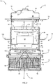
FIG. 2 is a partial side elevation cross-section view of the insect trap assembly taken along line 2-2 shown inFIG. 1 ; -
FIG. 3 is a perspective view of a damper assembly of the insect trap assembly shown inFIG. 1 with a pair of damper doors oriented in a closed position; -
FIG. 4 is a view similar toFIG. 3 and shows one of the damper doors or flaps in an open position and another damper door or flap removed; -
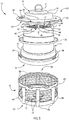
FIG. 5 is a view similar toFIG. 1 and shows a removable retaining cage exploded from the insect trap assembly; -
FIG. 6 is a detailed view of a locking mechanism formed between the retaining cage and the housing of the insect trap assembly taken along line 6-6 shown inFIG. 1 ; -
Fig. 1 shows aninsect trap assembly 10 according to the present invention.Insect trap assembly 10 includes a cover or aroof 12 that generally overlies a housing body orhousing 14 and a trap orcage 16 that is removably connected tohousing 14 and constructed to retain insects.Roof 12 includes anexterior surface 18 that is oriented to face an operating environment and aninterior surface 20 that generally underliesexterior surface 18 and faces atop surface 22 ofhousing 14.Roof 12 includes aperimeter 24 that defines a footprint ofroof 12. Although shown as generally circular, it is appreciated thatperimeter 24 could have any shape. - Still referring to
Fig. 1 ,exterior surface 18 ofroof 12 is bounded on its radial edges byperimeter 24 and includes a number of ridges, contours, ortiers 26 that extend in a gravitational direction relative to the intended orientation ofroof 12 during use oftrap assembly 10. Although shown as having a generally upward directed convex shape, it is appreciated thatexterior surface 18 ofroof 12 could have a concave or toroidal shape with respect toperimeter 24 and a centerline, indicated byline 28, ofassembly 10. Such a construction would allowroof 12 oftrap assembly 10 to retain an amount of water, whether provided by a user or as rainfall, to attract insects to trapassembly 10. As explained further below, one aspect of the present invention is to provide a number of insect attractants so as to draw intended targets to the trapping device. Water is only one such attractant and can be provided byroof 12 ofassembly 10, as explained above, and/or provided by other structures associated withhousing 14 and/orcage 16, - A number of
posts 30 extend betweeninterior surface 20 ofroof 12 andtop surface 22 ofhousing 14.Posts 30 are preferably spaced about a circumference associated with aradial perimeter 32 oftop surface 22 ofhousing 14.Posts 30 define agap 34 betweeninterior surface 20 ofroof 12 andtop surface 22 ofhousing 14, As explained further below,gap 34 is shaped to allow insects to pass into the space betweenroof 12 andhousing 14 and to be drawn and/or forced through the operational features oftrap assembly 10. It is appreciated that although threeposts 30 are shown, other numbers of posts may be provided to create the offset orgap 34 betweenroof 12 andhousing 14. - The
roof 12 preferably contains a hangingring 11 in the middle of itsexterior surface 18 for hanging thetrap 10 by a hook or other mounting apparatus. It is appreciated that there may be alternative ways to mounttrap 10, such as by a pole stand or hung from a chain. It is also appreciated that the mounting means may be located at other areas oftrap 10 besides theroof 12, such as onhousing 14. - The
roof 12 optionally containssolar cell 86 for powering the various electrical components located in or ontrap 10. It is appreciated that there may be a varying number ofsolar cells 86 and that they may be located anywhere ontrap 10, such as onroof 12 orhousing 14. - Still referring to
Fig. 1 , theradial perimeter 32 ofhousing 14 receivesposts 30 through corresponding receivingholes 36 spaced about a circumference associated with the radially positioning ofposts 30. Theposts 30 are fixed withinholes 36 by an attachment means, such as bolts or screws 38, to prevent vertical movement ofposts 30. It is contemplated that posts 30 may be fixed by other means, such as by welding or an adhesive. Theposts 30 are extended downward intoholes 36 to a depth that is able to receive an attachment means, such as screws 38. - The
radial perimeter 32 is constructed of a reinforced plastic to provide radial strength tohousing 14 and support for the weight of the upper elements. Theradial perimeter 32 may be asleeve 41 with acavity 40 to receive theupper perimeter 42 of thehousing 14 within thecavity 40. Thesleeve 41 is slid over theupper perimeter 42 to receive the edge of theupper perimeter 42. Thesleeve 41 may be fixedly attached to the housing body by bolts or screws 38, or other attachment means. It is appreciated that theradial perimeter 32 may alternatively be a piece that is attached parallel to theupper perimeter 42 by a fastening means, such as a bolt or screw. It is also appreciated that theradial perimeter 32 may be provided as either a piece separate fromhousing 14, or a reinforced edge onhousing 14 itself Further, althoughhousing 14 is shown to have a generally cylindrical shape, it is appreciated thathousing 14 could have any shape. - Referring to
Fig. 1 andFig. 2 , a screen or a firstprotective screen 46 is disposed across thetop surface 22 ofhousing 14. Firstprotective screen 46 includes an exposedtop surface 49 that faces theinterior surface 20 of theroof 12 and abottom surface 53 that underlies thetop surface 49 and faces inwardly into the interior 84 ofhousing 14. Theprotective screen 46 is grated to provide for a plurality of preferablysmall openings 48 that allow air flow and small insects to pass throughscreen 46, but do not allow larger foreign objects to pass there beyond. Theprotective screen 46 is coupled to theinner wall 50 of thehousing 14 and suspended over the entiretop surface 22 ofhousing 14. - Insects attracted to the trap are drawn into the
trap 10 through thegap 34 betweenposts 30 and enter the space betweenroof 12 andhousing 14. Insects then enter thehousing 14 by passing through theopenings 48 ofprotective screen 46 and pass to the interior 84 ofhousing 14. The insects pass the operational features disposed in theinterior 84 ofhousing 14 and exit thehousing 14 by passing downward through abottom base 52 ofhousing 14 and into the attached retainingcage 16. - Referring to
Fig. 1 andFig. 5 ,bottom base 52 ofhousing 14 has a generally cylindrical shape and corresponds to the shape of thehousing 14 but widens in a concave manner to provide an expanding diameter orifice oropening 95. It is appreciated thatbottom base 52 may be shaped in a number of ways and may not expand in diameter. Thebottom base 52 is sized to overlap theupper perimeter 66 of retainingcage 16 to securely couple thehousing 14 to the retainingcage 16. Thebottom base 52 may also have alocking mechanism 54 consisting of lockingholes 56 for receivingcorresponding lock pieces 58 of the retainingcage 16. - The retaining
cage 16 is disposed below thehousing 14 and fixably attached to capture insects exiting thebottom base 52 ofhousing 14. As insects exitbottom base 52, they are retained within the confines ofcage 16. Thecage 16 is a generally drum-shaped structure with an open top 60 and closed bottom 62. It is supported by aframe 64 that has anupper perimeter 66,lower perimeter 68 and connectingrods 70 that connect the upper 66 and lower 68 perimeters, The connectingrods 70 are preferably spaced about a circumference associated with a radial perimeter ofcage 16. A mesh netting 72 is lined within the interior of the retainingcage 16 to cover thespaces 74 created betweenrods 70. The netting 72 prevents insects from escaping the retainingcage 16, visual inspection of the contents of thecage 16 by a user, and allows the air directedhousing 14 toegress trap assembly 10. - Referring to
Fig. 2 ,trap assembly 10 is configured for operation with a number of optional attractants. One such attractant is the generation of light rays. Alight assembly 76 is coupled to theinterior surface 20 ofroof 12 by one or more mountingbrackets 78. Theinterior surface 20 may attach mountingbrackets 78 to receive the ends of one or moreUV light bulbs 80 or other light sources. It is appreciated that there are alternative ways to mountlight bulbs 80 within theinterior surface 20 ofroof 12, and that the light assembly may be mounted on different areas on thetrap 10. Thelight assembly 76 is attached to a power source, such as an AV power supply, battery source, or solar powered cells. The power source may be located on or intrap 10 or externally provided. - Another attractant contemplated is carbon dioxide or a carbon
dioxide releasing substance 81. Theinner wall 50 of the housing is coated with asubstance 81, such as titanium dioxide, which releases carbon dioxide when exposed to UV light rays. It is appreciated that other carbon dioxide releasing substances may be used as attractants to draw insect into the trap's vicinity. It is also appreciated that the substance may be coated at various locations on the trap, such as on theinterior surface 20 ofroof 12 or on the exterior surface ofhousing 14 to name but a few. - Another attractant contemplated is sitting water, which may be provided by a
water tray 136 coupled to the exterior surface 51 ofhousing 14 to collect water. Thewater tray 136 may be removable or permanent and may be attached to thehousing 14 via a number of methods, such as by screws or by being slidably fitted around the housing's 14 circumference. - Insects that enter
housing 14 by passing through theopenings 48 ofprotective screen 46 pass through a number of operational features located in theinterior 84 ofhousing 14. Within the interior 84 ofhousing 14 is afan assembly 82 which is fixably attached to theinner wall 50 ofhousing 14 by bolts 83, or the like, and suspended in the middle of the interior 84. Thefan assembly 82 is attached to theinner wall 50 by a number ofrigid suspension rods 88 that are bolted toinner wall 50 and attached to thebottom portion 85 offan assembly 82. Thesuspension rods 88 are located so that they do not interfere with movement ofblades 90 of thefan assembly 82. - The
fan assembly 82 hasrotatable blades 90 that preferably rotate in a horizontal plane that is aligned between the firstprotective screen 46 and a secondprotective screen 91. It is contemplated thatblades 90 may be provided at different pitches in order to create the desired air flow or vacuum effect. It is also contemplated that thefan assembly 82 may be located at different locations within theinterior 84 ofhousing 14. That isfan assembly 82 need not be centrally located and/or can be disposed nearer one ofscreens - Second
protective screen 91 is disposed belowfan assembly 82 and includes anupper surface 93 that faces inwardly toward thehousing interior 84 and abottom surface 92 that generally underliesupper surface 93 and faces adamper assembly 96.Protective screen 91 is grated to provide for a plurality ofsmall openings 94 that allow air flow and small insects to pass through theopenings 94. Theprotective screen 91 is coupled to theinner wall 50 of thehousing 14 and is suspended over the entire bottom opening 95 of thehousing 14.Screen 91 prevents unintended objects from inadvertently passing intohousing 14 but is constructed to allow insects to pass fairly unobstructed therethrough. - A
damper assembly 96 is coupled tobottom base 52.Damper assembly 96 includes two damper flaps 98 that each independently rotate between open and closed positions. The damper flaps 98 are preferably semi-circular to collectively cover thecircular opening 95. When there is no air-flow through thetrap 10, damper flaps 98 are in a closed position and cover thebottom opening 95 of thehousing 14 to prevent insects from escaping retainingcage 16. When there is air-flow through thetrap 10, damper flaps 98 are in an open position and provide aspace 99 to allow insects to be passed into the retainingcage 16. In an open position, the damper flaps 98 extend to a position that is preferably less than ninety degrees and extend outwardly into the attached retainingcage 16. Full extension of the damper flaps 98 is limited by stop-bars 100 which provide support and prohibit movement of theflaps 98. - The
bars 100 are attached to theinside wall 102 ofbottom base 52 bypivot pins 104 that are attached inwardly from thestraight edge 108 offlaps 98. Along eachstraight edge 108 areweighted rods 1 06 which are preferably made of a metal material, to create a desired weighted balance of eachflap 98. When thefan assembly 82 is off, and/or theblades 90 are not rotating, the damper flaps 98 are in a closed position. When the fan assembly is on and theblades 90 are rotating, the damper flaps 98 are in an open position and moved there by the air-flow throughtrap assembly 10. It is appreciated thatweighted rods 106 may be made of any weighted material. Regardless of the material they are constructed of,rods 106 are orientated relative to therespective flap 98 and pivot pins 104 to bias the respective flap toward the closed position. - Referring to
Fig. 3 , the damper flaps 98 align at theirstraight edges 108 to completely conceal theopening 95 and prevent insects from escaping the retainingcage 16. Theweighted rods 106 at thestraight edge 108 of theflaps 98 bias theflaps 98 toward a closed position when no air is flowing through the trap. - Referring to
Fig. 4 , when thedamper flap 98 is in an open position, theflap 98 is rotated aboutpivot pin 104 to disposeflap 98 at an angle that is preferably less than ninety degrees relative to the closed position and less than center with respect to the axis defined by thepivot 104 and the center of gravity of theflap 98. Theflap 98 is prevented from extending further by stop-bar 100 which is disposed directly behindflap 98 and is fixably attached to theinside wall 102 ofbottom base 52. Specifically, notch 110 located on stop-bar 100 abutsflap 98 to prevent further rotation. This disposition providesspace 99 which allows insects to pass outwardly from thehousing 14 and into the retainingcage 16. - Referring to
Figure 6 , thelocking mechanism 54 of thebottom base 52 to the retainingcage 16 consists ofholes 56 at the bottom base which receive thecorresponding lock pieces 58 of the top of the retainingcage 16. Thelock pieces 58 are fitted with theholes 56. The user then rotates thebottom base 52 and retainingcage 16 in opposite directions to secure the lockingpieces 58 within theholes 56. In a locked position, thelock pieces 58 are unable to slide out ofholes 56. To unlock the retainingcage 16, the user rotates thebottom base 52 and the retaining cage in opposite rotational directions as used to secure. Thelock pieces 58 are then permitted to slide out ofholes 56 and the retainingcage 16 can be removed from thebottom base 52 for cleaning, or the like. - The present invention has been described in terms of the preferred embodiment, and it is recognized that equivalents, alternatives, and modifications, aside from those expressly stated, are possible and within the scope of the appending claims.
Claims (13)
- An insect trap (10) comprising:a housing (14) comprising:a roof (12) defined by an exterior surface (18) and an interior surface (20);a housing body (14) depending downwardly below the roof (12), the housing body (14) defined by an open top (22), an inner surface (50), and an open bottom (52); anda cage (16) removably attached to the open bottom (52) of the housing body (14) and defined by an open top (60), an inner surface (72), and a closed bottom (62);a light source (76) attached to the roof (12);a first screen (46) disposed across the open top (22) of the housing body (14), the first screen (46) having a plurality of passages (48) that are each shaped to allow air and insects to pass through the first screen (46);a fan assembly (82) surrounded by the housing body (14) and disposed between the first screen (46) and the bottom (52) of the housing body (14), the fan assembly (82) being supported by the inner surface (50) of the housing body (14) and including a rotatable fan blade (90) configured to draw air through the housing (14) in a direction from the first screen (46) toward the bottom (52) of the housing body (14); anda damper assembly (96) secured to the housing body (14) below the bottom (52) of the housing body (14), the damper assembly (96) comprising:characterized bya first and a second damper shield (98), each damper shield (98) having a generally semi-circular planar shape defined by an arc connected at both ends by a straight edge (108);a coupling arrangement (104) that independently couples each of the first and second damper shields (98) to the housing body (14) such that each damper shield (98) is rotatably attached to the housing body (14) such that the first and second damper shields (98) swing independently toward a closed position when the fan (82) is off and swing toward an open position when the fan (82) is on;an attractant (81) disposed on the inner surface (50) of the housing body (14) and configured to release carbon dioxide;a second screen (91) disposed across the open bottom (52) of the housing body (14), the second screen (91) having a plurality of passages (94) that are each shaped to allow air and insects to pass through the second screen (91); andthe damper assembly (96) further comprising:a first stop bar and a second stop bar (100), each stop bar (100) being configured to limit rotation of a respective one of the first and second damper shields (98) so that less than 90 degrees is provided between the closed position and the open position of each of the first and second damper shields (98); anda weighted rod (106) coupled to each of the first damper shield and the second damper shield (98), each weighted rod (106) positioned within a perimeter of the respective damper shield (98) and the weighted rod (106) extending substantially parallel to the straight edge (108) of the respective damper shield (98) and positioned relative to the coupling arrangement to bias the respective one of the first damper shield and the second damper shield (98) toward the closed position.
- The insect trap of claim 1, wherein the coupling arrangement includes a set of pivot pins (104) and each pivot pin (104) is disposed proximate a linear side (108) of the generally semi-circular planar shape of a respective one of the first and the second damper shields (98).
- The insect trap of claim 1, wherein the attractant (81) is a titanium dioxide material.
- The insect trap of claim 1, wherein the roof (12) is transparent.
- The insect trap of claim 1, further comprising a twist mechanism (54) between the cage (16) and the housing body (14) that allows the cage (16) to be removed from the housing body (16) and which seals a perimeter of the open bottom (52) of the housing body (14) when the cage (16) is secured thereto.
- The insect trap of claim 1, further comprising a mounting apparatus (11) fixably attached to the housing (14).
- The insect trap of claim 6, wherein the mounting apparatus is a hanging hook (11) attached to the roof (12).
- The insect trap of claim 1, further comprising a water tray (136) disposed on the exterior of the housing (14).
- The insect trap of claim 8, wherein the water tray (136) is circumferentially disposed on the exterior of the housing (14).
- The insect trap of claim 1, wherein the first stop bar and the second stop bar (100) limit rotation of the respective damper shield (98) in an opening direction.
- The insect trap of claim 1, wherein the first and second damper shields (98) obstruct a generally circular opening (95) when in the closed position.
- The insect trap of claim 1, wherein the coupling arrangement comprises a pivot pin (104) that defines the axis of rotation of each respective damper shield (98), each pivot pin (104) extending beyond a perimeter of the respective damper shield (98) proximate opposite ends of each semi-circle arc and inward from the straight edge (108) of the respective damper shield (98).
- The insect trap of claim 1, wherein the roof (12) contains solar cells (86) for providing electrical energy.
Applications Claiming Priority (2)
| Application Number | Priority Date | Filing Date | Title |
|---|---|---|---|
| US13/680,527 US9049855B2 (en) | 2012-11-19 | 2012-11-19 | Insect trap having an air-actuated damper |
| PCT/US2013/057244 WO2014077932A1 (en) | 2012-11-19 | 2013-08-29 | Insect trap having an air-actuated damper |
Publications (3)
| Publication Number | Publication Date |
|---|---|
| EP2919583A1 EP2919583A1 (en) | 2015-09-23 |
| EP2919583A4 EP2919583A4 (en) | 2016-07-27 |
| EP2919583B1 true EP2919583B1 (en) | 2019-05-22 |
Family
ID=50726619
Family Applications (1)
| Application Number | Title | Priority Date | Filing Date |
|---|---|---|---|
| EP13854502.5A Active EP2919583B1 (en) | 2012-11-19 | 2013-08-29 | Insect trap having an air-actuated damper |
Country Status (4)
| Country | Link |
|---|---|
| US (1) | US9049855B2 (en) |
| EP (1) | EP2919583B1 (en) |
| ES (1) | ES2741436T3 (en) |
| WO (1) | WO2014077932A1 (en) |
Families Citing this family (58)
| Publication number | Priority date | Publication date | Assignee | Title |
|---|---|---|---|---|
| US9326497B2 (en) * | 2012-12-19 | 2016-05-03 | Dynamic Solutions Worldwide, LLC | Solar powered insect trap |
| AU2014223364C1 (en) | 2013-03-01 | 2018-02-15 | Arthropod Biosciences, Llc | Insect trap device and method of using |
| ES2952696T3 (en) | 2013-11-27 | 2023-11-03 | Procter & Gamble | Insect catching device |
| SG11201608318WA (en) * | 2014-04-26 | 2016-11-29 | Procter & Gamble | Insect trap device and method of using |
| US9717228B2 (en) * | 2014-07-24 | 2017-08-01 | Seoul Viosys Co., Ltd. | Insect trap using UV LED lamp |
| US9706764B2 (en) * | 2014-07-24 | 2017-07-18 | Seoul Viosys Co., Ltd. | Insect trap using UV LED lamp |
| CN107404866A (en) | 2015-01-12 | 2017-11-28 | 宝洁公司 | Insect trapping device and method of use |
| ES2796284T3 (en) * | 2015-02-25 | 2020-11-26 | Maurizio Magnani | Device to monitor and trap insects of the Culicidae population |
| USD777291S1 (en) | 2015-05-28 | 2017-01-24 | Dynamic Solutions Worldwide, LLC | Insect trap housing |
| JP6802267B2 (en) | 2015-05-29 | 2020-12-16 | エコラボ ユーエスエー インコーポレイティド | Devices and methods for attracting and capturing flying insects |
| US10021871B1 (en) * | 2015-06-05 | 2018-07-17 | Thomas Paul Cogley | Mobile insect killing system |
| US10021869B1 (en) * | 2015-06-05 | 2018-07-17 | Thomas Paul Cogley | Mosquito destructor system |
| US10091980B1 (en) * | 2015-06-05 | 2018-10-09 | Thomas Paul Cogley | Bed bug detector system |
| US10091981B1 (en) * | 2015-06-05 | 2018-10-09 | Thomas Paul Cogley | Flea destructor system |
| KR102536913B1 (en) * | 2015-09-25 | 2023-05-30 | 서울바이오시스 주식회사 | Insect trap |
| CN108347912A (en) * | 2015-11-06 | 2018-07-31 | 吴承财 | Hornet acquisition equipment |
| KR20170131148A (en) * | 2016-05-18 | 2017-11-29 | 서울바이오시스 주식회사 | Insect trap |
| USD818559S1 (en) | 2016-05-20 | 2018-05-22 | Ecolab Usa Inc. | Insect trap |
| PT109433A (en) * | 2016-06-07 | 2017-12-07 | Filipe Pinheiro Pinto Sobreiro Luís | MACHINE FOR INSECT CAPTURE, COUNTING AND MONITORING |
| CN106472458B (en) * | 2016-09-24 | 2018-05-25 | 东莞市青平电子科技有限公司 | Water curtain type insect trap |
| US10006619B1 (en) | 2016-12-28 | 2018-06-26 | WLC Enterprises, Inc. | Combination LED lighting and fan apparatus |
| US10393357B2 (en) | 2016-12-28 | 2019-08-27 | WLC Enterprises, Inc. | Combination built-in air flow mechanism, grow lighting and bug killer |
| US20180288993A1 (en) * | 2017-04-06 | 2018-10-11 | John W Hock Company | Packaged stealthy mosquito trap |
| US10368536B2 (en) * | 2017-05-01 | 2019-08-06 | Joshua Kenneth Pearce | Insect trap |
| KR20190019763A (en) * | 2017-08-18 | 2019-02-27 | 서울바이오시스 주식회사 | Insect trap |
| US10791726B2 (en) * | 2017-11-28 | 2020-10-06 | Ningbo Dayang Industry And Trade Co., Ltd. | Mosquito-killing device |
| CA2995537A1 (en) * | 2018-02-16 | 2019-08-16 | Maxtech Mosquito Control Inc. | Smart bulb |
| CN108651409B (en) * | 2018-03-26 | 2021-06-01 | 张素平 | A insect killer for forestry deinsectization be convenient for installation |
| US10772314B1 (en) * | 2018-06-27 | 2020-09-15 | Edward Caba | Pest trap |
| CN109518795A (en) * | 2018-11-26 | 2019-03-26 | 南安瑾颐商贸有限公司 | A kind of drainage ditch automation descaling machine being sprayed mosquitocide using pressure difference |
| US10736309B1 (en) * | 2018-11-27 | 2020-08-11 | Thomas Paul Cogley | Bed bug detector system |
| US11477976B2 (en) * | 2019-06-28 | 2022-10-25 | Epic Universal Technologies, Llc | Street light mosquito zapper |
| CN111869637A (en) * | 2020-07-02 | 2020-11-03 | 珠海格力电器股份有限公司 | Insect catching device with escape prevention structure and air conditioner |
| US20220022441A1 (en) * | 2020-07-24 | 2022-01-27 | Ap&G Co., Inc. | Flying insect trap with enhanced illumination |
| CN112640866A (en) * | 2020-09-28 | 2021-04-13 | 张晨欣 | Compression induction type circulating air bag one-way opening and closing multi-cavity cricket storage catching device |
| US20220132824A1 (en) * | 2020-10-30 | 2022-05-05 | 19 Thrasio Nineteen, Inc. | Insect capture device |
| CN214102884U (en) * | 2020-12-02 | 2021-09-03 | 浙江硕而博科技股份有限公司 | Mosquito killing lamp |
| CN112931449B (en) * | 2021-01-26 | 2022-07-15 | 杭州卫康有害生物防治有限公司 | A mosquito killing device with a cleaning mechanism |
| CN112931458A (en) * | 2021-02-04 | 2021-06-11 | 浙江硕而博科技股份有限公司 | A mosquito killer |
| CN112772603A (en) * | 2021-02-05 | 2021-05-11 | 浙江硕而博科技股份有限公司 | Mosquito killer lamp with manual function |
| US20220248654A1 (en) * | 2021-02-08 | 2022-08-11 | Stratex Partners LLC | Insect trap assembly and method of use |
| US11284610B1 (en) * | 2021-03-17 | 2022-03-29 | Howard Sowers | System and method for a mosquito trap |
| EP4062758A1 (en) * | 2021-03-24 | 2022-09-28 | Premal B.V. | Insect trap |
| CN113331171B (en) * | 2021-07-02 | 2022-06-21 | 潍坊科技学院 | A plant incubator insect repellent device |
| USD990613S1 (en) * | 2021-09-09 | 2023-06-27 | Yan Liu | Mosquito killer |
| US12302885B2 (en) * | 2021-10-18 | 2025-05-20 | Woodstream Corporation | Insect trap receptacle |
| US12642262B2 (en) * | 2022-01-12 | 2026-06-02 | Woodstream Corporation | Moth screen for insect traps |
| USD1038317S1 (en) * | 2022-11-16 | 2024-08-06 | Jiaqi Wang | Insect trap |
| UA129734C2 (en) * | 2022-12-30 | 2025-07-16 | Анастасія Романівна Романова | INSECT TRAP |
| UA130774C2 (en) | 2023-02-20 | 2026-05-13 | Анастасія Романівна Романова | Device for attracting and collecting insects |
| CN116508722B (en) * | 2023-06-16 | 2023-09-29 | 广州创鲜农业发展有限公司 | Guava plant pest capturing equipment and trapping method |
| US12274254B2 (en) * | 2023-08-07 | 2025-04-15 | Meizhen LI | Solar mosquito killer lamp |
| CN220777144U (en) * | 2023-08-16 | 2024-04-16 | 浙江小正科技有限公司 | Aromatherapy mosquito killer |
| US12402618B2 (en) * | 2023-08-17 | 2025-09-02 | Pic Corporation | Insect eliminating device with simulated flame and vacuum suction element |
| CN220630759U (en) * | 2023-08-18 | 2024-03-22 | 佛山市格林盈璐电器科技有限公司 | Mosquito catching device |
| EP4548760B1 (en) * | 2023-08-18 | 2025-10-08 | Foshan GreenYellow Electric Technology Co., Ltd. | Mosquito trap |
| US20250194577A1 (en) * | 2023-12-16 | 2025-06-19 | Sunday Okpala-Ezechukwu | Electric Insect Zapper with Integrated Fruit Flies Bait Tray |
| US20250280815A1 (en) * | 2024-03-08 | 2025-09-11 | Foshan Greenyellow Electric Technology Co., Ltd. | Carbon dioxide-lured mosquito trapping device |
Family Cites Families (25)
| Publication number | Priority date | Publication date | Assignee | Title |
|---|---|---|---|---|
| US1807550A (en) | 1930-05-02 | 1931-05-26 | Louis J L Rector | Insect trap |
| US2236698A (en) | 1940-05-25 | 1941-04-01 | Louis J L Rector | Combined insect trap and traffic light |
| US2893161A (en) | 1958-04-10 | 1959-07-07 | Frank S Reid | Suction-blower type illuminated insect trap |
| JPS5118677A (en) | 1974-08-05 | 1976-02-14 | Ryuufu Kuroodo | |
| US4282673A (en) | 1979-06-21 | 1981-08-11 | Focks Dana A | Flying insect trap |
| US4788789A (en) | 1987-12-21 | 1988-12-06 | The United States Of America As Represented By The Secretary Of The Army | Collapsible insect trap |
| US4794725A (en) | 1988-03-28 | 1989-01-03 | Allen Numerick | Insect trap |
| US5255468A (en) | 1991-07-26 | 1993-10-26 | Bugvac U.S.A., Inc. | Insect attracting and capturing apparatus |
| US5157865A (en) | 1991-10-03 | 1992-10-27 | Chang Che Yuan | Cantilever type mosquito catcher |
| US5329725A (en) * | 1993-06-07 | 1994-07-19 | Bible Donald W | Bug light and bag apparatus |
| AU730886B2 (en) | 1997-08-25 | 2001-03-15 | Earth Chemical Co. Ltd. | Method for catching flea and apparatus for catching flea |
| KR20020021466A (en) | 2000-09-15 | 2002-03-21 | 이경원, 김윤환 | Mosquito control apparatus with the effect of air cleaning |
| ITMI20011276A1 (en) | 2001-06-18 | 2002-12-18 | Mo El Srl | COLLECTION CONTAINER FOR INSECTICIDE EQUIPMENT AND EQUIPMENT TO CAPTURE INSECTS AND SIMILAR EQUIPPED WITH SUCH CONTAINER |
| US20050060926A1 (en) * | 2001-07-20 | 2005-03-24 | Kyeong-Won Lee | Mosquito attracting and killing apparatus with air cleaning function |
| US6990768B1 (en) * | 2004-04-05 | 2006-01-31 | Thomas William Boston | Device for eliminating mosquitos |
| US7036269B1 (en) | 2004-10-14 | 2006-05-02 | Chang-Hao Chen | Multipurpose mosquito trap lamp |
| CA2543218A1 (en) * | 2006-04-06 | 2007-10-06 | Sylvain Roy | Bug-vac light |
| US20080168702A1 (en) | 2006-10-27 | 2008-07-17 | Delta Search Labs, Inc. | Insect trap |
| KR100981145B1 (en) * | 2008-10-07 | 2010-09-10 | 한국수력원자력 주식회사 | Voluntary Distributed Processing System and Method for Thermal Hydraulic Analysis |
| KR20100078220A (en) * | 2008-12-30 | 2010-07-08 | 이동명 | Nail cutter |
| KR101123248B1 (en) | 2009-10-09 | 2012-03-21 | 주식회사 에이엔티에코영농 | Eradication device for harmful insect |
| US8240082B1 (en) | 2010-03-25 | 2012-08-14 | Fall Kenneth G | Check valve for insect traps |
| US8402691B2 (en) | 2010-05-21 | 2013-03-26 | Bantix Worldwide Pty. Ltd. | Insect trap |
| US8479438B1 (en) * | 2010-08-04 | 2013-07-09 | Vincent J. Wilhelmi | Arthropod abatement device |
| KR101283662B1 (en) | 2010-12-31 | 2013-07-08 | (주)에이엔티이십일 | Harmful insect grasping equipment |
-
2012
- 2012-11-19 US US13/680,527 patent/US9049855B2/en active Active
-
2013
- 2013-08-29 ES ES13854502T patent/ES2741436T3/en active Active
- 2013-08-29 EP EP13854502.5A patent/EP2919583B1/en active Active
- 2013-08-29 WO PCT/US2013/057244 patent/WO2014077932A1/en not_active Ceased
Non-Patent Citations (1)
| Title |
|---|
| None * |
Also Published As
| Publication number | Publication date |
|---|---|
| EP2919583A1 (en) | 2015-09-23 |
| US20140137462A1 (en) | 2014-05-22 |
| EP2919583A4 (en) | 2016-07-27 |
| US9049855B2 (en) | 2015-06-09 |
| ES2741436T3 (en) | 2020-02-11 |
| WO2014077932A1 (en) | 2014-05-22 |
Similar Documents
| Publication | Publication Date | Title |
|---|---|---|
| US9049855B2 (en) | Insect trap having an air-actuated damper | |
| EP2934108B1 (en) | Solar powered insect trap | |
| KR102603570B1 (en) | A noxious insect luring and capturing device attached to a pillar | |
| US20110030266A1 (en) | Flying insect capture apparatus | |
| US20100229459A1 (en) | Devices for trapping insects | |
| KR100945366B1 (en) | Green a noxious insect control device | |
| JP3136423U (en) | Pest trap | |
| US20150173338A1 (en) | Apparatus and Method for Trapping Flying Insects | |
| KR20130139531A (en) | Harmful insect grasping equipment | |
| US7024815B1 (en) | Lamp plus-insect exterminator | |
| JP3141997U (en) | Pest trap | |
| CN104229351A (en) | Solar garbage collection tank with insect trap function | |
| KR200396720Y1 (en) | Birds-beasts rid and Harmful insect grasping equipment | |
| CN204259678U (en) | A kind of new type disinsection lamp | |
| KR100632277B1 (en) | Reptile | |
| KR102263751B1 (en) | Apparatus for capturing insects | |
| KR102673367B1 (en) | Folding lightweight insect trap | |
| CN200983801Y (en) | Electronic mosquito suction machine | |
| KR101393105B1 (en) | Bug capturing device of air drop type | |
| KR100537635B1 (en) | Apparatus to catch harmful insects | |
| CN202184063U (en) | a mosquito killer lamp | |
| KR100753758B1 (en) | Pest control | |
| KR100632278B1 (en) | Reptile | |
| CN104585154A (en) | Automatic hole closing type illumination electric insect trap | |
| CA2705167A1 (en) | Flying insect capture apparatus |
Legal Events
| Date | Code | Title | Description |
|---|---|---|---|
| PUAI | Public reference made under article 153(3) epc to a published international application that has entered the european phase |
Free format text: ORIGINAL CODE: 0009012 |
|
| 17P | Request for examination filed |
Effective date: 20150609 |
|
| AK | Designated contracting states |
Kind code of ref document: A1 Designated state(s): AL AT BE BG CH CY CZ DE DK EE ES FI FR GB GR HR HU IE IS IT LI LT LU LV MC MK MT NL NO PL PT RO RS SE SI SK SM TR |
|
| AX | Request for extension of the european patent |
Extension state: BA ME |
|
| DAX | Request for extension of the european patent (deleted) | ||
| RA4 | Supplementary search report drawn up and despatched (corrected) |
Effective date: 20160623 |
|
| RIC1 | Information provided on ipc code assigned before grant |
Ipc: A01M 1/06 20060101ALI20160617BHEP Ipc: A01M 1/02 20060101AFI20160617BHEP Ipc: A01M 1/08 20060101ALI20160617BHEP Ipc: E04D 13/03 20060101ALI20160617BHEP |
|
| GRAP | Despatch of communication of intention to grant a patent |
Free format text: ORIGINAL CODE: EPIDOSNIGR1 |
|
| STAA | Information on the status of an ep patent application or granted ep patent |
Free format text: STATUS: GRANT OF PATENT IS INTENDED |
|
| INTG | Intention to grant announced |
Effective date: 20181211 |
|
| GRAS | Grant fee paid |
Free format text: ORIGINAL CODE: EPIDOSNIGR3 |
|
| GRAA | (expected) grant |
Free format text: ORIGINAL CODE: 0009210 |
|
| STAA | Information on the status of an ep patent application or granted ep patent |
Free format text: STATUS: THE PATENT HAS BEEN GRANTED |
|
| AK | Designated contracting states |
Kind code of ref document: B1 Designated state(s): AL AT BE BG CH CY CZ DE DK EE ES FI FR GB GR HR HU IE IS IT LI LT LU LV MC MK MT NL NO PL PT RO RS SE SI SK SM TR |
|
| REG | Reference to a national code |
Ref country code: GB Ref legal event code: FG4D |
|
| REG | Reference to a national code |
Ref country code: CH Ref legal event code: EP |
|
| REG | Reference to a national code |
Ref country code: IE Ref legal event code: FG4D |
|
| REG | Reference to a national code |
Ref country code: DE Ref legal event code: R096 Ref document number: 602013055897 Country of ref document: DE |
|
| REG | Reference to a national code |
Ref country code: AT Ref legal event code: REF Ref document number: 1134961 Country of ref document: AT Kind code of ref document: T Effective date: 20190615 |
|
| REG | Reference to a national code |
Ref country code: NL Ref legal event code: MP Effective date: 20190522 |
|
| REG | Reference to a national code |
Ref country code: LT Ref legal event code: MG4D |
|
| PG25 | Lapsed in a contracting state [announced via postgrant information from national office to epo] |
Ref country code: NO Free format text: LAPSE BECAUSE OF FAILURE TO SUBMIT A TRANSLATION OF THE DESCRIPTION OR TO PAY THE FEE WITHIN THE PRESCRIBED TIME-LIMIT Effective date: 20190822 Ref country code: FI Free format text: LAPSE BECAUSE OF FAILURE TO SUBMIT A TRANSLATION OF THE DESCRIPTION OR TO PAY THE FEE WITHIN THE PRESCRIBED TIME-LIMIT Effective date: 20190522 Ref country code: NL Free format text: LAPSE BECAUSE OF FAILURE TO SUBMIT A TRANSLATION OF THE DESCRIPTION OR TO PAY THE FEE WITHIN THE PRESCRIBED TIME-LIMIT Effective date: 20190522 Ref country code: HR Free format text: LAPSE BECAUSE OF FAILURE TO SUBMIT A TRANSLATION OF THE DESCRIPTION OR TO PAY THE FEE WITHIN THE PRESCRIBED TIME-LIMIT Effective date: 20190522 Ref country code: LT Free format text: LAPSE BECAUSE OF FAILURE TO SUBMIT A TRANSLATION OF THE DESCRIPTION OR TO PAY THE FEE WITHIN THE PRESCRIBED TIME-LIMIT Effective date: 20190522 Ref country code: PT Free format text: LAPSE BECAUSE OF FAILURE TO SUBMIT A TRANSLATION OF THE DESCRIPTION OR TO PAY THE FEE WITHIN THE PRESCRIBED TIME-LIMIT Effective date: 20190922 Ref country code: SE Free format text: LAPSE BECAUSE OF FAILURE TO SUBMIT A TRANSLATION OF THE DESCRIPTION OR TO PAY THE FEE WITHIN THE PRESCRIBED TIME-LIMIT Effective date: 20190522 Ref country code: AL Free format text: LAPSE BECAUSE OF FAILURE TO SUBMIT A TRANSLATION OF THE DESCRIPTION OR TO PAY THE FEE WITHIN THE PRESCRIBED TIME-LIMIT Effective date: 20190522 |
|
| PG25 | Lapsed in a contracting state [announced via postgrant information from national office to epo] |
Ref country code: GR Free format text: LAPSE BECAUSE OF FAILURE TO SUBMIT A TRANSLATION OF THE DESCRIPTION OR TO PAY THE FEE WITHIN THE PRESCRIBED TIME-LIMIT Effective date: 20190823 Ref country code: BG Free format text: LAPSE BECAUSE OF FAILURE TO SUBMIT A TRANSLATION OF THE DESCRIPTION OR TO PAY THE FEE WITHIN THE PRESCRIBED TIME-LIMIT Effective date: 20190822 Ref country code: LV Free format text: LAPSE BECAUSE OF FAILURE TO SUBMIT A TRANSLATION OF THE DESCRIPTION OR TO PAY THE FEE WITHIN THE PRESCRIBED TIME-LIMIT Effective date: 20190522 Ref country code: RS Free format text: LAPSE BECAUSE OF FAILURE TO SUBMIT A TRANSLATION OF THE DESCRIPTION OR TO PAY THE FEE WITHIN THE PRESCRIBED TIME-LIMIT Effective date: 20190522 |
|
| REG | Reference to a national code |
Ref country code: AT Ref legal event code: MK05 Ref document number: 1134961 Country of ref document: AT Kind code of ref document: T Effective date: 20190522 |
|
| PG25 | Lapsed in a contracting state [announced via postgrant information from national office to epo] |
Ref country code: SK Free format text: LAPSE BECAUSE OF FAILURE TO SUBMIT A TRANSLATION OF THE DESCRIPTION OR TO PAY THE FEE WITHIN THE PRESCRIBED TIME-LIMIT Effective date: 20190522 Ref country code: DK Free format text: LAPSE BECAUSE OF FAILURE TO SUBMIT A TRANSLATION OF THE DESCRIPTION OR TO PAY THE FEE WITHIN THE PRESCRIBED TIME-LIMIT Effective date: 20190522 Ref country code: EE Free format text: LAPSE BECAUSE OF FAILURE TO SUBMIT A TRANSLATION OF THE DESCRIPTION OR TO PAY THE FEE WITHIN THE PRESCRIBED TIME-LIMIT Effective date: 20190522 Ref country code: CZ Free format text: LAPSE BECAUSE OF FAILURE TO SUBMIT A TRANSLATION OF THE DESCRIPTION OR TO PAY THE FEE WITHIN THE PRESCRIBED TIME-LIMIT Effective date: 20190522 Ref country code: AT Free format text: LAPSE BECAUSE OF FAILURE TO SUBMIT A TRANSLATION OF THE DESCRIPTION OR TO PAY THE FEE WITHIN THE PRESCRIBED TIME-LIMIT Effective date: 20190522 Ref country code: RO Free format text: LAPSE BECAUSE OF FAILURE TO SUBMIT A TRANSLATION OF THE DESCRIPTION OR TO PAY THE FEE WITHIN THE PRESCRIBED TIME-LIMIT Effective date: 20190522 |
|
| REG | Reference to a national code |
Ref country code: ES Ref legal event code: FG2A Ref document number: 2741436 Country of ref document: ES Kind code of ref document: T3 Effective date: 20200211 |
|
| REG | Reference to a national code |
Ref country code: DE Ref legal event code: R097 Ref document number: 602013055897 Country of ref document: DE |
|
| PG25 | Lapsed in a contracting state [announced via postgrant information from national office to epo] |
Ref country code: SM Free format text: LAPSE BECAUSE OF FAILURE TO SUBMIT A TRANSLATION OF THE DESCRIPTION OR TO PAY THE FEE WITHIN THE PRESCRIBED TIME-LIMIT Effective date: 20190522 |
|
| PLBE | No opposition filed within time limit |
Free format text: ORIGINAL CODE: 0009261 |
|
| STAA | Information on the status of an ep patent application or granted ep patent |
Free format text: STATUS: NO OPPOSITION FILED WITHIN TIME LIMIT |
|
| PG25 | Lapsed in a contracting state [announced via postgrant information from national office to epo] |
Ref country code: TR Free format text: LAPSE BECAUSE OF FAILURE TO SUBMIT A TRANSLATION OF THE DESCRIPTION OR TO PAY THE FEE WITHIN THE PRESCRIBED TIME-LIMIT Effective date: 20190522 |
|
| 26N | No opposition filed |
Effective date: 20200225 |
|
| PG25 | Lapsed in a contracting state [announced via postgrant information from national office to epo] |
Ref country code: PL Free format text: LAPSE BECAUSE OF FAILURE TO SUBMIT A TRANSLATION OF THE DESCRIPTION OR TO PAY THE FEE WITHIN THE PRESCRIBED TIME-LIMIT Effective date: 20190522 |
|
| PG25 | Lapsed in a contracting state [announced via postgrant information from national office to epo] |
Ref country code: LU Free format text: LAPSE BECAUSE OF NON-PAYMENT OF DUE FEES Effective date: 20190829 Ref country code: MC Free format text: LAPSE BECAUSE OF FAILURE TO SUBMIT A TRANSLATION OF THE DESCRIPTION OR TO PAY THE FEE WITHIN THE PRESCRIBED TIME-LIMIT Effective date: 20190522 Ref country code: LI Free format text: LAPSE BECAUSE OF NON-PAYMENT OF DUE FEES Effective date: 20190831 Ref country code: SI Free format text: LAPSE BECAUSE OF FAILURE TO SUBMIT A TRANSLATION OF THE DESCRIPTION OR TO PAY THE FEE WITHIN THE PRESCRIBED TIME-LIMIT Effective date: 20190522 Ref country code: CH Free format text: LAPSE BECAUSE OF NON-PAYMENT OF DUE FEES Effective date: 20190831 |
|
| REG | Reference to a national code |
Ref country code: BE Ref legal event code: MM Effective date: 20190831 |
|
| PG25 | Lapsed in a contracting state [announced via postgrant information from national office to epo] |
Ref country code: IE Free format text: LAPSE BECAUSE OF NON-PAYMENT OF DUE FEES Effective date: 20190829 |
|
| PG25 | Lapsed in a contracting state [announced via postgrant information from national office to epo] |
Ref country code: BE Free format text: LAPSE BECAUSE OF NON-PAYMENT OF DUE FEES Effective date: 20190831 |
|
| PG25 | Lapsed in a contracting state [announced via postgrant information from national office to epo] |
Ref country code: CY Free format text: LAPSE BECAUSE OF FAILURE TO SUBMIT A TRANSLATION OF THE DESCRIPTION OR TO PAY THE FEE WITHIN THE PRESCRIBED TIME-LIMIT Effective date: 20190522 |
|
| PG25 | Lapsed in a contracting state [announced via postgrant information from national office to epo] |
Ref country code: IS Free format text: LAPSE BECAUSE OF FAILURE TO SUBMIT A TRANSLATION OF THE DESCRIPTION OR TO PAY THE FEE WITHIN THE PRESCRIBED TIME-LIMIT Effective date: 20190922 |
|
| PG25 | Lapsed in a contracting state [announced via postgrant information from national office to epo] |
Ref country code: MT Free format text: LAPSE BECAUSE OF FAILURE TO SUBMIT A TRANSLATION OF THE DESCRIPTION OR TO PAY THE FEE WITHIN THE PRESCRIBED TIME-LIMIT Effective date: 20190522 Ref country code: HU Free format text: LAPSE BECAUSE OF FAILURE TO SUBMIT A TRANSLATION OF THE DESCRIPTION OR TO PAY THE FEE WITHIN THE PRESCRIBED TIME-LIMIT; INVALID AB INITIO Effective date: 20130829 |
|
| PG25 | Lapsed in a contracting state [announced via postgrant information from national office to epo] |
Ref country code: MK Free format text: LAPSE BECAUSE OF FAILURE TO SUBMIT A TRANSLATION OF THE DESCRIPTION OR TO PAY THE FEE WITHIN THE PRESCRIBED TIME-LIMIT Effective date: 20190522 |
|
| P01 | Opt-out of the competence of the unified patent court (upc) registered |
Effective date: 20230524 |
|
| PGFP | Annual fee paid to national office [announced via postgrant information from national office to epo] |
Ref country code: ES Payment date: 20250901 Year of fee payment: 13 |
|
| PGFP | Annual fee paid to national office [announced via postgrant information from national office to epo] |
Ref country code: DE Payment date: 20250724 Year of fee payment: 13 |
|
| PGFP | Annual fee paid to national office [announced via postgrant information from national office to epo] |
Ref country code: IT Payment date: 20250723 Year of fee payment: 13 |
|
| PGFP | Annual fee paid to national office [announced via postgrant information from national office to epo] |
Ref country code: GB Payment date: 20250725 Year of fee payment: 13 |
|
| PGFP | Annual fee paid to national office [announced via postgrant information from national office to epo] |
Ref country code: FR Payment date: 20250725 Year of fee payment: 13 |