EP2919356A2 - Redundante unterbrechungsfreie stromversorgungssysteme - Google Patents
Redundante unterbrechungsfreie stromversorgungssysteme Download PDFInfo
- Publication number
- EP2919356A2 EP2919356A2 EP15157305.2A EP15157305A EP2919356A2 EP 2919356 A2 EP2919356 A2 EP 2919356A2 EP 15157305 A EP15157305 A EP 15157305A EP 2919356 A2 EP2919356 A2 EP 2919356A2
- Authority
- EP
- European Patent Office
- Prior art keywords
- ups
- upss
- common reference
- controller
- ring bus
- Prior art date
- Legal status (The legal status is an assumption and is not a legal conclusion. Google has not performed a legal analysis and makes no representation as to the accuracy of the status listed.)
- Pending
Links
- 238000000034 method Methods 0.000 claims description 23
- 238000010586 diagram Methods 0.000 description 31
- 238000012546 transfer Methods 0.000 description 12
- 230000006870 function Effects 0.000 description 9
- 239000003990 capacitor Substances 0.000 description 5
- 238000004364 calculation method Methods 0.000 description 4
- 230000010355 oscillation Effects 0.000 description 4
- 230000003068 static effect Effects 0.000 description 4
- 230000000694 effects Effects 0.000 description 3
- 238000012423 maintenance Methods 0.000 description 3
- 230000001360 synchronised effect Effects 0.000 description 3
- 238000006243 chemical reaction Methods 0.000 description 2
- 238000012544 monitoring process Methods 0.000 description 2
- 230000007704 transition Effects 0.000 description 2
- 238000003491 array Methods 0.000 description 1
- 230000015556 catabolic process Effects 0.000 description 1
- 238000012937 correction Methods 0.000 description 1
- 238000006731 degradation reaction Methods 0.000 description 1
- 230000007613 environmental effect Effects 0.000 description 1
- 230000003116 impacting effect Effects 0.000 description 1
- 230000001939 inductive effect Effects 0.000 description 1
- 230000007257 malfunction Effects 0.000 description 1
- 238000007726 management method Methods 0.000 description 1
- 238000004519 manufacturing process Methods 0.000 description 1
- 230000007935 neutral effect Effects 0.000 description 1
- 230000003287 optical effect Effects 0.000 description 1
- 238000012545 processing Methods 0.000 description 1
- 239000004065 semiconductor Substances 0.000 description 1
- 230000035945 sensitivity Effects 0.000 description 1
- 239000007787 solid Substances 0.000 description 1
- 230000001052 transient effect Effects 0.000 description 1
Images


Classifications
-
- G—PHYSICS
- G05—CONTROLLING; REGULATING
- G05F—SYSTEMS FOR REGULATING ELECTRIC OR MAGNETIC VARIABLES
- G05F3/00—Non-retroactive systems for regulating electric variables by using an uncontrolled element, or an uncontrolled combination of elements, such element or such combination having self-regulating properties
- G05F3/02—Regulating voltage or current
-
- H—ELECTRICITY
- H02—GENERATION; CONVERSION OR DISTRIBUTION OF ELECTRIC POWER
- H02J—CIRCUIT ARRANGEMENTS OR SYSTEMS FOR SUPPLYING OR DISTRIBUTING ELECTRIC POWER; SYSTEMS FOR STORING ELECTRIC ENERGY
- H02J3/00—Circuit arrangements for AC mains or AC distribution networks
- H02J3/38—Arrangements for parallely feeding a single network by two or more generators, converters or transformers
- H02J3/40—Synchronising a generator for connection to a network or to another generator
-
- H—ELECTRICITY
- H02—GENERATION; CONVERSION OR DISTRIBUTION OF ELECTRIC POWER
- H02J—CIRCUIT ARRANGEMENTS OR SYSTEMS FOR SUPPLYING OR DISTRIBUTING ELECTRIC POWER; SYSTEMS FOR STORING ELECTRIC ENERGY
- H02J3/00—Circuit arrangements for AC mains or AC distribution networks
- H02J3/38—Arrangements for parallely feeding a single network by two or more generators, converters or transformers
- H02J3/46—Controlling of the sharing of output between the generators, converters, or transformers
-
- H—ELECTRICITY
- H02—GENERATION; CONVERSION OR DISTRIBUTION OF ELECTRIC POWER
- H02J—CIRCUIT ARRANGEMENTS OR SYSTEMS FOR SUPPLYING OR DISTRIBUTING ELECTRIC POWER; SYSTEMS FOR STORING ELECTRIC ENERGY
- H02J4/00—Circuit arrangements for mains or distribution networks not specified as AC or DC
-
- H—ELECTRICITY
- H02—GENERATION; CONVERSION OR DISTRIBUTION OF ELECTRIC POWER
- H02J—CIRCUIT ARRANGEMENTS OR SYSTEMS FOR SUPPLYING OR DISTRIBUTING ELECTRIC POWER; SYSTEMS FOR STORING ELECTRIC ENERGY
- H02J9/00—Circuit arrangements for emergency or stand-by power supply, e.g. for emergency lighting
- H02J9/04—Circuit arrangements for emergency or stand-by power supply, e.g. for emergency lighting in which the distribution system is disconnected from the normal source and connected to a standby source
- H02J9/06—Circuit arrangements for emergency or stand-by power supply, e.g. for emergency lighting in which the distribution system is disconnected from the normal source and connected to a standby source with automatic change-over, e.g. UPS systems
- H02J9/061—Circuit arrangements for emergency or stand-by power supply, e.g. for emergency lighting in which the distribution system is disconnected from the normal source and connected to a standby source with automatic change-over, e.g. UPS systems for DC powered loads
-
- H—ELECTRICITY
- H02—GENERATION; CONVERSION OR DISTRIBUTION OF ELECTRIC POWER
- H02J—CIRCUIT ARRANGEMENTS OR SYSTEMS FOR SUPPLYING OR DISTRIBUTING ELECTRIC POWER; SYSTEMS FOR STORING ELECTRIC ENERGY
- H02J9/00—Circuit arrangements for emergency or stand-by power supply, e.g. for emergency lighting
- H02J9/04—Circuit arrangements for emergency or stand-by power supply, e.g. for emergency lighting in which the distribution system is disconnected from the normal source and connected to a standby source
- H02J9/06—Circuit arrangements for emergency or stand-by power supply, e.g. for emergency lighting in which the distribution system is disconnected from the normal source and connected to a standby source with automatic change-over, e.g. UPS systems
- H02J9/062—Circuit arrangements for emergency or stand-by power supply, e.g. for emergency lighting in which the distribution system is disconnected from the normal source and connected to a standby source with automatic change-over, e.g. UPS systems for AC powered loads
Definitions
- the field of the invention relates generally to uninterruptible power supplies, and more particularly, to implementing uninterruptible power supplies in a ring bus architecture.
- Robust power systems enable supplying power to one or more loads.
- Such power systems may include combinations of generation, transport, rectification, inversion and conversion of power to supply energy for electronic, optical, mechanical, and/or nuclear applications and loads.
- practical considerations include cost, size, reliability, and ease of implementation.
- UPSs uninterruptible power supplies
- UPSs facilitate supplying power to a load.
- UPSs facilitate ensuring that power is continuously supplied to one or more critical loads, even when one or more components of a power system fail.
- UPSs provide a redundant power source.
- UPSs may be utilized in a number of applications (e.g., utility substations, industrial plants, marine systems, high security systems, hospitals, datacomm and telecomm centers, semiconductor manufacturing sites, nuclear power plants, etc.). Further, UPSs may be utilized in high, medium, or low power applications. For example, UPSs may be used in relatively small power systems (e.g., entertainment or consumer systems) or microsystems (e.g., a chip-based system).
- different power sources such as separate UPSs
- the power sources may interfere with one another. If the power sources are not synchronized with one another, they may begin to override one another, causing oscillations or other undesirable effects, and impacting power delivered to one or more loads. Further, if separate UPSs are all operating relative to a common reference angle, and a utility becomes disconnected from at least one of the separate UPSs, the common reference angle for one UPS may drift and become different from the common reference angle for another UPS, which may impact load sharing and stability of the power system.
- a system in one aspect, includes a utility, a plurality of uninterruptible power supplies (UPSs), a ring bus, at least one load electrically coupled to the plurality of UPSs and the ring bus, and a controller communicatively coupled to the plurality of UPSs, the controller configured to determine a common reference angle while the utility is disconnected from at least one UPS of the plurality of UPSs, calculate a phase angle for each UPS of the plurality of UPSs, wherein the phase angle for each UPS is calculated relative to the common reference angle, and control operation of each UPS based on the respective calculated phase angles.
- UPSs uninterruptible power supplies
- a controller for controlling a power supply system that includes a utility, a plurality of uninterruptible power supplies (UPSs), a ring bus, and at least one load electrically coupled to the plurality of UPSs and the ring bus.
- the controller includes a processor, and a memory device communicatively coupled to the processor, the memory device storing executable instructions configured to cause the processor to determine a common reference angle while the utility is disconnected from at least one UPS of the plurality of UPSs, calculate a phase angle for each UPS of the plurality of UPSs, wherein the phase angle for each UPS is calculated relative to the common reference angle, and control operation of each UPS based on the respective calculated phase angles.
- a method of controlling a power supply system includes a utility, a plurality of uninterruptible power supplies (UPSs), a ring bus, and at least one load electrically coupled to the plurality of UPSs and the ring bus.
- the method includes determining a common reference angle while the utility is disconnected from at least one UPS of the plurality of UPSs, calculating, using a controller communicatively coupled to the plurality of UPSs, a phase angle for each UPS of the plurality of UPSs, wherein the phase angle for each UPS is calculated relative to the common reference angle, and controlling operation of each UPS based on the respective calculated phase angles.
- a utility is electrically coupled to a plurality of uninterruptible power supplies.
- the plurality of uninterruptible power supplies are arranged in a ring bus configuration and configured to supply power to at least one load.
- a control device is communicatively coupled to the plurality of uninterruptible power supplies. The control device is configured to determine a common reference angle in the event that the utility becomes disconnected from at least one of the plurality of uninterruptible power supplies.
- Fig. 1 is a schematic diagram of an exemplary redundant isolated-parallel (IP) uninterruptible power supply (UPS) system 100.
- system 100 includes a plurality of UPSs 102 arranged in a ring architecture, or parallel architecture, as described herein.
- system 100 includes a first UPS 104, a second UPS 106, a third UPS 108, and a fourth UPS 110 in the exemplary embodiment.
- system 100 may include any number of UPSs 102 that enable system 100 to function as described herein.
- system 100 is a three wire system.
- system 100 may be a four wire system (i.e., a system including a neutral wire to each load).
- UPSs 102 are static double conversion UPSs (i.e., true on-line system systems). Both static and rotary UPSs may require droop control techniques for both voltage and frequency. In some cases, droop control for frequency alone may be sufficient. In some embodiments, droop control techniques are adapted depending on whether a load is linear or non-linear.
- System 100 facilitates providing power to one or more loads 120.
- one or more utilities 122 function as a power source and provide power to loads 120.
- Utilities 122 may provide alternating current (AC) or direct current (DC) power to system 100.
- AC alternating current
- DC direct current
- system 100 utilizes UPSs 102 to keep power flowing to loads 120, as described herein.
- system 100 includes a first load 124, a second load 126, a third load 128, and a fourth load 130.
- system 100 may include any number of loads 120 that enable system 100 to function as described herein.
- Each load 120 is electrically coupled between an associated UPS 102 and a ring bus 132.
- each load 120 is coupled to ring bus 132 via an associated load circuit breaker 134.
- ring bus 132 includes a plurality of ring bus circuit breakers 136.
- loads 120 may be coupled directly to ring bus 132 or may be coupled between UPSs 102.
- system 100 may include additional UPSs 138 coupled directly to ring bus 132.
- each UPS 102 is electrically coupled between an input switchgear 140 and an output switchgear 142.
- Input switchgears 140 are electrically coupled to paralleling switchgears 144, which are in turn electrically coupled to utility 122 through an associated transformer 146.
- each paralleling switchgear 144 is also electrically coupled to one or more grounds 148.
- Switchgears 140, 142, and 144 include may include local circuits, remote synchronization circuits, and/or software to facilitate attenuating disturbances, interference, and/or crosstalk on ring bus 132 to provide clean power to loads 120.
- each output switchgear 142 is electrically coupled directly to an associated load 120, and coupled to ring bus 132 through an associated choke 150 (e.g., an inductor).
- UPSs 102 may interfere with one another and/or start to override one another, causing oscillations or other undesirable effects.
- a controller (not shown in Fig. 1 ) controls operation UPSs 102. More specifically, the controller controls a phase angle, ⁇ , of an output voltage of each UPS 102, as described herein.
- the phase angle ⁇ is calculated relative to a common reference angle, ⁇ .
- This common reference may be taken from different sources.
- the common reference may be a common utility input voltage from utility 122 or a common IP bus voltage from ring bus 132.
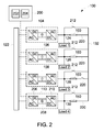
- Fig. 2 is a simplified diagram of system 100.
- a controller 200 is communicatively coupled to each of first UPS 104, second UPS 106, third UPS 108, and fourth UPS 110.
- Controller 200 may include its own power system (not shown) such as a dedicated energy source (e.g., a battery).
- controller 200 is coupled to a substitute controller (not shown) that may be used in the event that controller 200 fails. Controller 200 may control power distribution and management of system 100 over a relatively large geographic area.
- controller 200 is implemented by a processor 202 communicatively coupled to a memory device 204 for executing instructions.
- executable instructions are stored in memory device 204.
- controller 200 may be implemented using any circuitry that enables controller 200 to control operation of UPSs 102 as described herein.
- controller 200 may include a state machine that learns or is preprogrammed to determine information relevant to which loads 120 require power. For example, controller 200 may dynamically determine what power resources will be needed and at what performance level and environmental conditions (e.g., temperature, humidity, time of day, etc.) those power resources will need to operate.
- Controller 200 may perform dynamic monitoring to determine whether a given load 120 is satisfied with the power delivered, and whether delivered power is free of harmonics, transients, etc.
- dynamic monitoring may include tracking resource usage to determine how much current or voltage should be delivered.
- Controller 200 may also monitor and/or control rapidity (i.e., bandwidth) and inverter capability (e.g., overload, reactive power, active power) to facilitate ensuring reliability of system 100 and minimizing performance degradation of UPSs 102.
- Controller 200 may also include a state machine scheduler configured to selectively activate and deactivate power resources, set voltage and current levels, and/or take power saving actions (e.g., reducing current delivery). Controller 200 may also track characteristics (e.g., static allocation of power) of system 100 to determine whether one or more components of system 100 should be put on standby or whether power should be diverted.
- a state machine scheduler configured to selectively activate and deactivate power resources, set voltage and current levels, and/or take power saving actions (e.g., reducing current delivery). Controller 200 may also track characteristics (e.g., static allocation of power) of system 100 to determine whether one or more components of system 100 should be put on standby or whether power should be diverted.
- controller 200 performs one or more operations described herein by programming processor 202.
- processor 202 may be programmed by encoding an operation as one or more executable instructions and by providing the executable instructions in memory device 204.
- Processor 202 may include one or more processing units (e.g., in a multi-core configuration). Further, processor 202 may be implemented using one or more heterogeneous processor systems in which a main processor is present with secondary processors on a single chip. As another illustrative example, processor 202 may be a symmetric multiprocessor system containing multiple processors of the same type.
- processor 202 may be implemented using any suitable programmable circuit including one or more systems and microcontrollers, microprocessors, reduced instruction set circuits (RISC), application specific integrated circuits (ASIC), programmable logic circuits, field programmable gate arrays (FPGA), and any other circuit capable of executing the functions described herein.
- processor 202 causes controller 200 to operate UPSs 102, as described herein.
- memory device 204 is one or more devices that enable information such as executable instructions and/or other data to be stored and retrieved.
- Memory device 204 may include one or more computer readable media, such as, without limitation, dynamic random access memory (DRAM), static random access memory (SRAM), a solid state disk, and/or a hard disk.
- Memory device 204 may be configured to store, without limitation, application source code, application object code, source code portions of interest, object code portions of interest, configuration data, execution events and/or any other type of data.
- UPSs 102 and loads 120 are electrically coupled to one another through chokes 150 and ring bus 132.
- Each UPS 102 includes a rectifier 206, an inverter 208, and a DC capacitor 210 in the exemplary embodiment.
- each load 120 is electrically coupled in parallel with an output capacitor (not shown), and each UPS 102 is electrically coupled in series with an inductor (not shown), in the exemplary embodiment.
- Each inductor and an associated output capacitor form an LC filter, and the phase angle ⁇ is a phase angle of the output voltage of a UPS 102 as measured across the output capacitor.
- a bypass switch 212 is coupled in parallel with each choke 150. Closing bypass switch 212 causes power flow to bypass an associated choke 150.
- Loads 120 can receive power from a local UPS 102 (e.g., first load 124 receiving power from first UPS 104) and from other UPSs 102 through choke 150. Accordingly, in the event that a local UPS 102 fails, a load 120 can receive power from other UPSs 102.
- controller 200 calculates an output voltage phase angle ⁇ for each UPS 102, and controller operates each UPS 102 at the calculated phase angle ⁇ .
- the output voltage of a given UPS 102 can be represented as 2 * V no min al ⁇ sin ⁇ t + ⁇ , where V nominal is the voltage of UPS 102, ⁇ is the frequency of AC power delivered by UPS 102 (e.g., 2 ⁇ *60 Hertz), and t is time.
- the phase angle ⁇ for each UPS 102 may be calculated using a variety of load sharing algorithms, as described herein.
- the load sharing algorithms are designed to facilitate equal sharing of power by UPSs 102.
- the phase angle ⁇ for each UPS 102 is calculated using only local load information (e.g., the phase angle ⁇ for first UPS 104 is calculated using load information for first load 124).
- phase angle ⁇ is retrieved from a look up table (e.g., on memory device 204) of stored values for a given load sharing algorithm.
- memory device 204 may include a read only memory (ROM) circuit having course values (e.g., every 20 degrees) and subdivisions of fine values (e.g., sub-degrees within each 20 degree range).
- ROM read only memory
- Fig. 3 is a diagram 300 illustrating one exemplary load sharing algorithm for calculating the phase angle ⁇ .
- the algorithm may be performed, for example, using controller 200.
- the x-axis represents the power to be delivered to the local load 120 associated with UPS 102
- the y-axis is the corresponding phase angle ⁇ for the output voltage of UPS 102. Accordingly, if UPS 102 does not include an associated load 120, it will try to supply a maximum power to ring bus 132, and in doing so, control the phase angle ⁇ to be +9°.
- P_UPS the power from the given UPS 102 to ring bus 132
- V 1 is the voltage of the given UPS 102
- V 2 is the voltage of ring bus 132
- ⁇ is the phase angle between V 1 and V 2
- x is an effective inductive impedance of the choke 150 associated with the given UPS 102. This equation applies to three-phase systems as well.
- the phase angle ⁇ varies linearly with P_Local_Load (i.e., ⁇ , L, and V are substantially constant.
- ⁇ is limited to plus or minus 9°. That is, ⁇ for a given UPS 102 can not be set greater than +9° or less than -9° in the exemplary embodiment. This facilitates high resolution and sensitivity of inverter control, while avoiding relatively large phase angle variations when load 120 is bypassed to ring bus 132.
- ⁇ may be limited to other values (e.g., plus or minus 10°) that enable system 100 to function as described herein.
- the phase angle ⁇ values obtained using diagram 300 may be stored in a look up table, for example, on memory device 204.
- the phase angle ⁇ may be calculated from Equation 2 using, for example, controller 200.
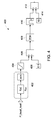
- Fig. 4 is a logic diagram of a slow power transfer algorithm 400 that may utilize a look up table based on diagram 300 or Equation 2 to calculate the phase angle ⁇ .
- Slow power transfer algorithm 400 may be performed, for example, using controller 200.
- Slow power transfer algorithm 400 facilitates reducing oscillations in system 100. Specifically, if controller 200 merely calculates the phase angles ⁇ and controls UPSs 102 to operate at the calculated phase angles ⁇ substantially instantaneously, UPSs 102 may rapidly change phase angles ⁇ in a relatively short period of time, which may introduce transient oscillations into system 100. Accordingly, slow power transfer algorithm 400 varies the phase angle ⁇ slowly to facilitate a smooth transition to the calculated phase angles ⁇ .
- phase angle calculation block 402 calculates the phase angle ⁇ (using, e.g., the look up table based on diagram 300 or Equation 2).
- a limiting block 404 limits the phase angle ⁇ to avoid extreme values. For example, limiting block 404 may limit the phase angle ⁇ to no greater than 9° and no less than -9°.
- a first product block 406 multiplies the phase angle ⁇ by a division factor 408.
- division factor 408 is 0.1.
- division factor 408 may be any value that enables slow power transfer algorithm 400 to function as described herein.
- a zero-order hold block 409 holds the value from first product block 406 for a predetermined hold time (e.g., 1 millisecond (ms)).
- a moving average block 410 then calculates a moving average over a predetermined time period (e.g., 10 ms).
- a second product block 412 multiplies the value from moving average block 410 by a multiplication factor 414.
- multiplication factor 414 is 10 (i.e., the inverse of division factor 408).
- multiplication factor 414 may be any value that enables slow power transfer algorithm 400 to function as described herein.
- the final value generated by second product block 412 is the phase angle ⁇ to which the associated UPS 102 is ultimately set. Accordingly, slow power transfer algorithm 400 gradually transitions UPSs 102 between calculated phase angles ⁇ .
- Fig. 5 is a logic diagram of an alternative load sharing algorithm 500 that may utilize a look up table based on diagram 300 or Equation 2 to calculate the phase angle ⁇ .
- load sharing algorithm 500 is substantially similar to slow power transfer algorithm 400 (shown in Fig. 4 ).
- Load sharing algorithm 500 may be performed, for example, using controller 200 (shown in Fig. 2 ).
- Load sharing algorithm 500 accounts for a situation when no load 120 is present for a given UPS 102, and follows a no load logic path 502 when no load 120 is present. For example, a load 120 may suddenly and/or unexpectedly be removed from UPS 102. Accordingly, load sharing algorithm 500 may be referred to as a no load algorithm.
- load sharing algorithm 500 provides a value of the DC voltage, DC_Link1, to a software reset-set (SR) flip-flop block 504. If the DC voltage is below a predetermined threshold voltage, flip-flop block 504 is reset at 0°. When flip-flop block 504 outputs 0°, a switch block 506 selects a slow power transfer logic path 508, and the logic proceeds identical to slow transfer power algorithm 400.
- DC_Link1 a software reset-set (SR) flip-flop block 504.
- flip-flip block 504 is set to 1°.
- switch block 506 selects no load logic path 502, and excludes slow power transfer logic path 508.
- a summing block 510 sums the 1° output of flip-flop block 504 with the output of limiting block 404.
- the final value generated by second summing block 510 is the phase angle ⁇ to which the associated UPS 102 is ultimately set.
- System 100 also facilitates hot swapping one or more UPSs 102 in and/or out of system 100. That is, system 100 facilitates swapping UPSs 102 in and out of system 100 during operation of system 100.
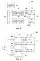
- Fig. 6 is a schematic diagram of a system 600 that illustrates hot swapping in third UPS 108. That is, system 600 initially includes first UPS 104 and second UPS 106, but not third UPS 108. Unless otherwise noted, system 600 is substantially similar to system 100 (shown in Figs. 1 and 2 ).
- a switch, or contactor, 602 is closed to electrically couple third UPS 108 to ring bus 132. At the moment that switch is closed, it is desirable that no power flows through the choke 150 associated with third UPS 108. To prevent power flow, the voltage on either side of choke 150 associated with third UPS 108 should be the same in phase and in frequency.
- Fig. 7 is a logic diagram of an alternative load sharing algorithm 700 that may utilize a look up table based on diagram 300 or Equation 2 to calculate the phase angle ⁇ .
- load sharing algorithm 700 is substantially similar to load sharing algorithm 500 (shown in Fig. 5 ).
- Load sharing algorithm 700 may be performed, for example, using controller 200 (shown in Fig. 2 ).
- Load sharing algorithm 700 facilitates swapping in a UPS, such as third UPS 108. Accordingly, load sharing algorithm 700 may also be referred to as a swapping-in algorithm. Specifically, when a UPS is swapped in, the phase angle ⁇ is not calculated using phase angle calculation block 402. Instead, the phase angle ⁇ is set at a predefined angle for a predetermined period of time. Specifically, when the UPS is swapped in by closing switch 602, a predefined angle block 702 provides a predefined phase angle, c, to a switch block 704, and first product block 406 takes the predefined phase angle c from switch block 704. In the exemplary embodiment, the predefined phase angle c is set equal to a phase angle of the voltage on ring bus 132. Accordingly, when the UPS is swapped in, there is no voltage across associated choke 150, and no power flows through choke 150.
- a timer block 706 controls when switch block 704 switches between supplying predefined phase angle c to first product block 406 and supplying the phase angle ⁇ output by limiting block 404 to first product block 406. Specifically, after a predetermined period of time, switch block 704 switches from supplying predefined phase angle c to first product block 406 to supplying the phase angle ⁇ output by limiting block 404 to first product block 406. Accordingly, after the predetermined period of time expires, the phase angle ⁇ for the swapped-in UPS is calculated using phase angle calculation block 402.
- Fig. 8 is a schematic diagram of a system 800 that illustrates hot swapping out first UPS 104 in accordance with a swapping-out algorithm.
- system 800 is substantially similar to system 100 (shown in Figs. 1 and 2 ).
- System 800 initially includes first UPS 104 and second UPS 106.
- system 800 includes a maintenance switch 802 (which is the same as bypass switch 212 (shown in Fig. 2 )) electrically coupled in parallel with the choke 150 associated with first UPS 104, a state switch module (SSM) 804 electrically coupled between first UPS 104 and associated choke 150, and a contactor 806 electrically coupled in parallel with SSM 804.
- SSM state switch module
- SSM 804 is a bi-directional thyristor module, capable of flowing current in either direction and capable of switching significantly faster than contactor 806.
- SSM 804 may be any switching device that enables system 800 to function as described herein.
- first UPS 104 Before swapping out first UPS 104, maintenance switch 802 is open, SSM 804 is open (i.e., not activated), and contactor 806 is closed.
- a default load sharing algorithm (such as load sharing algorithm 500 (shown in Fig. 5 )) is disabled. With the load sharing algorithm disabled, a phase angle of the voltage on ring bus 132 is measured, and first UPS 104 is made synchronized in phase and frequency with the voltage on ring bus 132. With first UPS 104 operating at the same phase angle and magnitude as the voltage on ring bus 132, no power flows through associated choke 150.
- maintenance switch 802 is closed. This connects first load 124 to ring bus 132, bypassing associated choke 150.
- SSM 804 is closed (i.e., activated), (ii) contactor 806 is opened, and (iii) SSM 804 is deactivated (i.e., opened). Because SSM 804 is capable of faster switching than contactor 806, utilizing SSM 804 enables disconnecting first UPS 104 from system 800 relatively quickly.
- Fig. 9 is a schematic diagram of a system 900 operating under normal operation. Unless otherwise indicated, system 900 is substantially similar to system 100, with like reference numerals indicating like components.
- System 900 includes a first UPS 104, a second UPS 106, and a third UPS 108 each connected to a common utility 122.
- a first load 124 is coupled between first UPS 104 and ring bus 132.
- additional loads may be coupled between second and third UPSs 106 and 108 and ring bus 132, such as loads 126 and 130 (shown in Fig. 2 ).
- a first phase locked loop 902, a second phase locked loop 904, and a third phase locked loop 906 provide phase angles ⁇ to first UPS 104, second UPS 106, and third UPS 108, respectively.
- First phase locked loop 902, second phase locked loop 904, and third phase locked loop 906 may be implemented, for example, by controller 200 (shown in Fig. 2 ).
- phase angles ⁇ are calculated relative to a common reference angle ⁇ .
- utility 122 is connected to first UPS 104, second UPS 106, and third UPS 108.
- the common reference angle ⁇ is the phase angle of the voltage of utility 122.
- the disconnected UPSs 102 may be unable use the phase angle of the voltage of utility 122 as the common reference angle ⁇ .
- the phase angles ⁇ should all be calculated relative to the same common reference angle ⁇ . Accordingly, the techniques described herein facilitate determining a common reference angle ⁇ while utility 122 is disconnected from one or more UPSs 102.
- Fig. 10 is a schematic diagram of a system 1000 that illustrates determining a common reference angle ⁇ when utility 122 is disconnected from every UPS 102. Unless otherwise indicated, system 1000 is substantially similar to system 900, with like reference numerals indicating like components.
- utility 122 is disconnected from first UPS 104, second UPS 106, and third UPS 108 (indicated by an open switch 1002).
- a voltage phase angle of ring bus 132 is used as the common reference angle ⁇ . That is, phase locked loops 902, 904, and 906 calculate their respective phase angles ⁇ relative to the voltage phase angle of ring bus 132, facilitating equal load sharing and overall stability of system 1000.
- Fig. 11 is a schematic diagram of a system 1100 that illustrates determining a common reference angle ⁇ when utility 122 is disconnected from only some UPSs 102. Unless otherwise indicated, system 1100 is substantially similar to system 900, with like reference numerals indicating like components.
- utility 122 is disconnected from first UPS 104, but remains connected to second UPS 106 and third UPS 108.
- first UPS 104 uses the voltage phase angle of ring bus 132 as the common reference angle ⁇
- second and third UPSs 106 and 108 use the voltage phase angle of utility 122 as the common reference angle ⁇ , instabilities and/or a malfunction in load sharing may occur, as UPSs 102 are not all using the same common reference angle ⁇ .
- all UPSs 102 produce a nominal voltage at the same angle and in phase with utility 122.
- first phase locked loop 902, second phase locked loop 904, and third phase locked loop 906 all use the voltage phase angle of ring bus 132 as the common reference angle ⁇ .
- each UPS 102 produces an output voltage at the same phase angle ⁇ relative to the voltage phase angle of ring bus 132.
- the phase angle ⁇ of each UPS 102 may be varied (e.g., using the load sharing algorithms described above) to facilitate load sharing in system 1100. Further, to keep the frequency of the output voltage of each UPS 102 similar to the input voltage frequency from utility 122, an incremental delta correction in the output voltage frequency is performed.
- UPSs 102 can only use the voltage phase angle of ring bus 132 as the common reference angle ⁇ when at least two UPSs 102 are connected to ring bus 132.
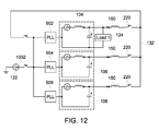
- Fig. 12 is a schematic diagram of a system 1200 that illustrates determining a common reference angle ⁇ when first connecting UPSs 102 to ring bus 132.
- system 1100 is substantially similar to system 900, with like reference numerals indicating like components.
- first UPS 104, second UPS 106, and third UPS 108 are connected to ring bus 132.
- first UPS 104 is about to be connected to ring bus 132 by closing switch 220 between first UPS 104 and ring bus 132.
- the method 1300 shown in Fig. 13 is performed.
- Method 1300 may be performed, for example, using controller 200 (shown in Fig. 2 ).
- the voltage on ring bus 132 is measured (e.g., using a voltage sensor (not shown)), and it is determined 1302 whether the ring bus voltage is approximately equal to (e.g., within plus or minus 5% of) a nominal root mean square (RMS) output voltage of UPS 102. If the ring bus voltage is approximately equal to the UPS output voltage, switch 220 is closed 1303 and the voltage phase angle of ring bus 132 is set 1304 as the common reference angle ⁇ . If the ring bus voltage is not approximately equal to the UPS output voltage (e.g., if the ring bus voltage is substantially zero), switch 220 is closed 1305 and the voltage phase angle of utility 122 is set 1306 as the common reference angle ⁇ .
- RMS root mean square
- the phase angle ⁇ is varied 1308 by a relatively small amount.
- the phase angle ⁇ may be varied by an amount from 0.1 to 0.5 degrees.
- This subroutine (e.g., steps 1308-1314) may be performed periodically until at least one additional UPS 102 is connected to ring bus 132.
- the hot swapping techniques discussed above are applicable when adding UPSs to 102 system 1200.
- the systems and methods described herein facilitate synchronizing a plurality of UPSs such that the plurality of UPSs do not interfere with or override one another.
- a control device uses a load sharing algorithm to calculate a phase angle for each UPS. The phase angle is calculated relative to a common reference angle, and the systems and methods described herein facilitate determining the common reference angle under different circumstances (e.g., when at least one UPS becomes disconnected from a utility).
- At least one technical effect of the systems and methods described herein includes (a) determining a common reference angle while a utility is disconnected from at least one UPS of a plurality of UPSs; (b) calculating a phase angle for each UPS of the plurality of UPSs, wherein the phase angle for each UPS is calculated relative to the common reference angle; and (c) controlling operation of each UPS based on the respective calculated phase angles.
Landscapes
- Engineering & Computer Science (AREA)
- Power Engineering (AREA)
- Physics & Mathematics (AREA)
- Electromagnetism (AREA)
- General Physics & Mathematics (AREA)
- Radar, Positioning & Navigation (AREA)
- Automation & Control Theory (AREA)
- Business, Economics & Management (AREA)
- Emergency Management (AREA)
- Supply And Distribution Of Alternating Current (AREA)
- Stand-By Power Supply Arrangements (AREA)
Applications Claiming Priority (2)
| Application Number | Priority Date | Filing Date | Title |
|---|---|---|---|
| US201461951281P | 2014-03-11 | 2014-03-11 | |
| US14/306,641 US9685820B2 (en) | 2014-03-11 | 2014-06-17 | Redundant uninterruptible power supply systems |
Publications (2)
| Publication Number | Publication Date |
|---|---|
| EP2919356A2 true EP2919356A2 (de) | 2015-09-16 |
| EP2919356A3 EP2919356A3 (de) | 2015-10-28 |
Family
ID=52669456
Family Applications (1)
| Application Number | Title | Priority Date | Filing Date |
|---|---|---|---|
| EP15157305.2A Pending EP2919356A3 (de) | 2014-03-11 | 2015-03-03 | Redundante unterbrechungsfreie stromversorgungssysteme |
Country Status (3)
| Country | Link |
|---|---|
| US (1) | US9685820B2 (de) |
| EP (1) | EP2919356A3 (de) |
| CN (1) | CN104917277B (de) |
Cited By (1)
| Publication number | Priority date | Publication date | Assignee | Title |
|---|---|---|---|---|
| EP3293851A1 (de) * | 2016-09-13 | 2018-03-14 | General Electric Company | Isoliertes paralleles ups-system mit drosselüberbrückungsschalter |
Families Citing this family (8)
| Publication number | Priority date | Publication date | Assignee | Title |
|---|---|---|---|---|
| US10340732B2 (en) | 2015-12-04 | 2019-07-02 | Schneider Electric It Corporation | Automatic UPS bypass load sharing |
| US10340808B2 (en) * | 2015-12-14 | 2019-07-02 | Acbel Polytech Inc. | Redundant power supply apparatus |
| US10284008B2 (en) | 2016-09-13 | 2019-05-07 | Abb Schweiz Ag | Isolated parallel ups system with fault location detection |
| US10630104B2 (en) | 2017-04-13 | 2020-04-21 | Schneider Electric It Corporation | Automatic current balancing for power systems |
| US10886775B2 (en) * | 2017-05-17 | 2021-01-05 | Toshiba International Corporation | Active multi-module switching system and method |
| CN110661332B (zh) * | 2018-06-29 | 2021-07-27 | 深圳中瀚云科技股份有限公司 | 一种用于计算设备的供电系统 |
| WO2020210106A1 (en) * | 2019-04-08 | 2020-10-15 | Covidien Lp | Power management schemes for surgical systems |
| CN111030285B (zh) * | 2019-12-20 | 2021-11-05 | 漳州科华技术有限责任公司 | 不间断电源的锁相实现方法及终端设备 |
Family Cites Families (59)
| Publication number | Priority date | Publication date | Assignee | Title |
|---|---|---|---|---|
| TW245848B (de) | 1991-09-18 | 1995-04-21 | Toshiba Kk | |
| AUPN592095A0 (en) | 1995-10-11 | 1995-11-02 | Invetech Operations Pty Ltd | Modular power supply |
| US5745356A (en) | 1996-06-25 | 1998-04-28 | Exide Electronics Corporation | Independent load sharing of AC power systems connected in parallel |
| US6191500B1 (en) | 1998-11-06 | 2001-02-20 | Kling Lindquist Partnership, Inc. | System and method for providing an uninterruptible power supply to a critical load |
| US6396170B1 (en) * | 2000-03-29 | 2002-05-28 | Powerware Corporation | Method and apparatus for coordinating uninterruptible power supply modules to provide scalable, redundant power |
| CN1423389A (zh) * | 2001-12-07 | 2003-06-11 | 广东志成冠军电子实业有限公司 | 总线控制的并联不间断电源(ups)系统 |
| ATE490591T1 (de) | 2002-09-10 | 2010-12-15 | Dewind Co | Betriebsverfahren für windenergieanlage mit übersynchroner kaskade |
| EP1559179A4 (de) | 2002-10-22 | 2006-07-12 | Youtility Inc | Hybrider stromwandler mit generator mitvariabler geschwindigkeit bzw. ununterbrechbarer stromversorgung |
| KR20050088107A (ko) | 2002-12-06 | 2005-09-01 | 일렉트릭 파워 리서치 인스티튜트 | 무정전 전원 공급기 및 발전기 시스템 |
| JP4099713B2 (ja) | 2003-07-10 | 2008-06-11 | 富士電機システムズ株式会社 | 無停電電源システムの制御方法および制御回路 |
| TW200505128A (en) | 2003-07-31 | 2005-02-01 | Digipower Mfg Inc | Improved uninterruptible switching power supply circuit having hot plugging battery module |
| US20090009005A1 (en) | 2003-10-02 | 2009-01-08 | Phoenixtec Power Co., Ltd. | Control method for parallel redundant power system |
| US20050073783A1 (en) | 2003-10-02 | 2005-04-07 | Phoenixtec Power Co., Ltd. | Parallel redundant power system and the control method for the same |
| US6803679B1 (en) | 2003-10-02 | 2004-10-12 | Phoenixtec Power Co., Ltd. | Parallel redundant power system and method for control of the power system |
| US7446433B2 (en) | 2004-01-23 | 2008-11-04 | American Power Conversion Corporation | Methods and apparatus for providing uninterruptible power |
| US7400066B2 (en) | 2004-06-23 | 2008-07-15 | Eaton Corporation | Apparatus and methods for UPS bypass monitoring and control |
| US7405494B2 (en) * | 2004-07-07 | 2008-07-29 | Eaton Corporation | AC power supply apparatus, methods and computer program products using PWM synchronization |
| US8754544B2 (en) | 2005-01-27 | 2014-06-17 | General Electric Company | Apparatus for synchronizing uninterruptible power supplies |
| US7456520B2 (en) | 2005-03-31 | 2008-11-25 | General Electric Company | Control system, method and product for uninterruptible power supply |
| US7566988B2 (en) | 2005-06-14 | 2009-07-28 | Liebert Corporation | Method and apparatus for monitoring UPS power sources |
| AU2006269496A1 (en) | 2005-07-06 | 2007-01-18 | Liebert Corporation | Maximized battery run-time in a parallel UPS system |
| WO2007035411A2 (en) | 2005-09-16 | 2007-03-29 | Satcon Technology Corporation | Slip-controlled, wound-rotor induction machine for wind turbine and other applications |
| US7638899B2 (en) | 2006-03-10 | 2009-12-29 | Eaton Corporation | Nested redundant uninterruptible power supply apparatus and methods |
| EP1890371A1 (de) | 2006-08-03 | 2008-02-20 | Michael J. Mosman | USV-Systemkonfiguration mit parallelen und von einander unabhängigen Modulen |
| DE102006051546A1 (de) | 2006-11-02 | 2008-05-08 | Nordex Energy Gmbh | Verfahren zum Betrieb einer Windenergieanlage mit einem doppelt gespeisten Asynchrongenerator sowie Windenergieanlage mit einem doppelt gespeisten Asynchrongenerator |
| CN101647170B (zh) | 2006-11-16 | 2013-11-13 | 康明斯发电Ip公司 | 发电系统及方法 |
| US7649758B2 (en) | 2006-11-30 | 2010-01-19 | Eaton Corporation | Power supply apparatus, methods and computer program products using D-Q domain based synchronization techniques |
| US7667351B2 (en) | 2007-04-27 | 2010-02-23 | Liebert Corporation | Method for pulse width modulation synchronization in a parallel UPS system |
| US20090009001A1 (en) | 2007-07-05 | 2009-01-08 | Liebert Corporation | Method and apparatus for synchronization of actions in a parallel ups system using a serial communications bus |
| DE102007021089B3 (de) | 2007-05-03 | 2008-12-11 | Piller Power Systems Gmbh | Verfahren zur Steuerung parallel geschalteter Ersatzstromquellen und Vorrichtung mit parallel geschalteten Ersatzstromquellen |
| DE102008024222A1 (de) | 2007-08-14 | 2009-02-26 | Karl-Friedrich Schilling Elektrotechnik Gmbh | Verfahren und Vorrichtung zur Bereitstellung von Regelleistung im Energieversorgungsbereich zur Frequenzstabilisierung eines elektrischen Netzes |
| US7980905B2 (en) | 2007-11-25 | 2011-07-19 | C-Mar Holdings, Ltd. | Method and apparatus for providing power to a marine vessel |
| CA2709279C (en) | 2007-12-12 | 2014-04-15 | Foss Maritime Company | Hybrid propulsion systems |
| US7952232B2 (en) | 2008-03-13 | 2011-05-31 | General Electric Company | Wind turbine energy storage and frequency control |
| US8035250B2 (en) | 2008-03-14 | 2011-10-11 | Liebert Corporation | System and method for load sharing in multi-module power supply systems |
| US20090273192A1 (en) | 2008-04-30 | 2009-11-05 | Guven Mustafa K | Doubly fed axial flux induction generator |
| US8120932B2 (en) | 2008-07-01 | 2012-02-21 | American Superconductor Corporation | Low voltage ride through |
| DE102009017244A1 (de) | 2009-04-09 | 2010-10-14 | Nordex Energy Gmbh | Verfahren zum Betreiben einer Windenergieanlage bei fehlender Verfügbarkeit eines externen Versorgungsnetzes und Windenergieanlage zur Ausführung des Verfahrens |
| US8022572B2 (en) | 2009-04-22 | 2011-09-20 | General Electric Company | Genset system with energy storage for transient response |
| US20110278932A1 (en) | 2010-05-13 | 2011-11-17 | Eaton Corporation | Uninterruptible power supply systems and methods using isolated interface for variably available power source |
| US8552589B2 (en) | 2010-05-14 | 2013-10-08 | Schneider Electric It Corporation | Digital control method for operating the UPS systems in parallel |
| AU2010257197A1 (en) | 2010-05-28 | 2011-12-15 | Mitsubishi Heavy Industries, Ltd. | Power supply device and method |
| US8373949B2 (en) | 2010-06-16 | 2013-02-12 | Transocean Sedco Forex Ventures Limited | Hybrid power plant for improved efficiency and dynamic performance |
| US20120068541A1 (en) | 2010-09-20 | 2012-03-22 | Eaton Corporation | Power supply systems and methods employing a ups interfaced generator |
| US8631275B2 (en) | 2010-12-28 | 2014-01-14 | Vestas Wind Systems A/S | Controller arrangement of an electrical power transfer system of a wind turbine |
| GB201110916D0 (en) | 2011-06-28 | 2011-08-10 | Rolls Royce Plc | Electrical distribution system |
| US8786262B2 (en) | 2011-07-25 | 2014-07-22 | Rolls-Royce Corporation | Systems and methods for synchronous power generation |
| US8772964B2 (en) | 2011-09-19 | 2014-07-08 | Schneider Electric It Corporation | Parallel control and protection for UPS |
| US9172271B2 (en) | 2011-09-19 | 2015-10-27 | Schneider Electric It Corporation | Parallel control and protection for UPS |
| CN202333831U (zh) | 2011-10-18 | 2012-07-11 | 山东省电力学校 | 新能源不间断供电系统 |
| DE102011089851B4 (de) | 2011-12-23 | 2013-04-11 | TelecityGroup Germany Gmbh | Vorrichtung zur unterbrechungsfreien Stromversorgung von elektrischen Verbrauchern und Verfahren zum Betrieb der Vorrichtung |
| KR101267513B1 (ko) | 2012-01-11 | 2013-05-24 | 주식회사 이온 | 무선통신을 이용한 ups 병렬 운전 제어 방법 |
| US9160202B2 (en) | 2012-01-31 | 2015-10-13 | General Electric Company | Control system for uninterruptible power supplies |
| US20150108759A1 (en) | 2012-02-20 | 2015-04-23 | Regen Technologies Pty Ltd | Variable Speed Gas Turbine Generation System and Method |
| CN202444318U (zh) | 2012-03-07 | 2012-09-19 | 山东电力集团公司临沂供电公司 | 一种多源智能供配电装置 |
| US10203735B2 (en) | 2012-03-21 | 2019-02-12 | Bloom Energy Corporation | Systems and methods for providing fuel cell power to a data center |
| CN202889279U (zh) | 2012-10-19 | 2013-04-17 | 北京索德电气工业有限公司 | 无刷双馈电机励磁控制装置 |
| US9379542B2 (en) | 2012-11-20 | 2016-06-28 | General Electric Company | System for multiple inverter-driven loads |
| US9882424B2 (en) | 2014-02-21 | 2018-01-30 | General Electric Company | Redundant uninterruptible power supply systems |
-
2014
- 2014-06-17 US US14/306,641 patent/US9685820B2/en active Active
-
2015
- 2015-03-03 EP EP15157305.2A patent/EP2919356A3/de active Pending
- 2015-03-11 CN CN201510105617.4A patent/CN104917277B/zh active Active
Non-Patent Citations (1)
| Title |
|---|
| None |
Cited By (4)
| Publication number | Priority date | Publication date | Assignee | Title |
|---|---|---|---|---|
| EP3293851A1 (de) * | 2016-09-13 | 2018-03-14 | General Electric Company | Isoliertes paralleles ups-system mit drosselüberbrückungsschalter |
| CN107819356A (zh) * | 2016-09-13 | 2018-03-20 | 通用电气公司 | 带有扼流圈旁路开关的隔离并联不间断电源系统 |
| US10199861B2 (en) | 2016-09-13 | 2019-02-05 | Abb Schweiz Ag | Isolated parallel UPS system with choke bypass switch |
| US11355957B2 (en) | 2016-09-13 | 2022-06-07 | Abb Schweiz Ag | Isolated parallel UPS system with choke bypass switch |
Also Published As
| Publication number | Publication date |
|---|---|
| US20150263566A1 (en) | 2015-09-17 |
| CN104917277A (zh) | 2015-09-16 |
| US9685820B2 (en) | 2017-06-20 |
| CN104917277B (zh) | 2019-12-24 |
| EP2919356A3 (de) | 2015-10-28 |
Similar Documents
| Publication | Publication Date | Title |
|---|---|---|
| US9882424B2 (en) | Redundant uninterruptible power supply systems | |
| US9685820B2 (en) | Redundant uninterruptible power supply systems | |
| EP2919363B1 (de) | Redundante unterbrechungsfreie stromversorgungssysteme | |
| EP2919350B1 (de) | Systeme und verfahren zur bereitstellung einer erhöhten fehlerstromfähigkeit in unterbrechungsfreien stromversorgungssystemen | |
| EP3008792B1 (de) | Systeme und verfahren zur mehrfachverwendung von multimodus-usv | |
| US8766474B2 (en) | Smart microgrid reconfigurable AC interface | |
| US9735615B2 (en) | Systems and methods for managing power backfeed in uninterruptible power supply systems | |
| Verma et al. | Decentralized Master-Slave operation of microgrid using current controlled distributed generation sources | |
| CN105006878B (zh) | 在不可中断电源系统中提供增加的故障电流能力的系统和方法 | |
| EP3035482A1 (de) | Systeme und verfahren zur implementierung von reihenkompensatoren in statischen usv | |
| EP2980959B1 (de) | Systeme und verfahren zur ausnutzung der stromfähigkeit in einer statischen usv | |
| EP2980960B1 (de) | Systeme und verfahren zur hybriden spannungs- und stromregelung in statischen unterbrechungsfreien stromversorgungssystemen |
Legal Events
| Date | Code | Title | Description |
|---|---|---|---|
| PUAI | Public reference made under article 153(3) epc to a published international application that has entered the european phase |
Free format text: ORIGINAL CODE: 0009012 |
|
| AK | Designated contracting states |
Kind code of ref document: A2 Designated state(s): AL AT BE BG CH CY CZ DE DK EE ES FI FR GB GR HR HU IE IS IT LI LT LU LV MC MK MT NL NO PL PT RO RS SE SI SK SM TR |
|
| AX | Request for extension of the european patent |
Extension state: BA ME |
|
| PUAL | Search report despatched |
Free format text: ORIGINAL CODE: 0009013 |
|
| AK | Designated contracting states |
Kind code of ref document: A3 Designated state(s): AL AT BE BG CH CY CZ DE DK EE ES FI FR GB GR HR HU IE IS IT LI LT LU LV MC MK MT NL NO PL PT RO RS SE SI SK SM TR |
|
| AX | Request for extension of the european patent |
Extension state: BA ME |
|
| RIC1 | Information provided on ipc code assigned before grant |
Ipc: H02J 3/46 20060101ALI20150922BHEP Ipc: H02J 9/06 20060101ALN20150922BHEP Ipc: H02J 3/40 20060101AFI20150922BHEP |
|
| STAA | Information on the status of an ep patent application or granted ep patent |
Free format text: STATUS: REQUEST FOR EXAMINATION WAS MADE |
|
| 17P | Request for examination filed |
Effective date: 20160428 |
|
| RBV | Designated contracting states (corrected) |
Designated state(s): AL AT BE BG CH CY CZ DE DK EE ES FI FR GB GR HR HU IE IS IT LI LT LU LV MC MK MT NL NO PL PT RO RS SE SI SK SM TR |
|
| RAP1 | Party data changed (applicant data changed or rights of an application transferred) |
Owner name: ABB SCHWEIZ AG |
|
| STAA | Information on the status of an ep patent application or granted ep patent |
Free format text: STATUS: EXAMINATION IS IN PROGRESS |
|
| 17Q | First examination report despatched |
Effective date: 20210305 |
|
| RAP3 | Party data changed (applicant data changed or rights of an application transferred) |
Owner name: ABB SCHWEIZ AG |
|
| STAA | Information on the status of an ep patent application or granted ep patent |
Free format text: STATUS: EXAMINATION IS IN PROGRESS |