EP2919168B1 - Portable electronic apparatus - Google Patents
Portable electronic apparatus Download PDFInfo
- Publication number
- EP2919168B1 EP2919168B1 EP13890788.6A EP13890788A EP2919168B1 EP 2919168 B1 EP2919168 B1 EP 2919168B1 EP 13890788 A EP13890788 A EP 13890788A EP 2919168 B1 EP2919168 B1 EP 2919168B1
- Authority
- EP
- European Patent Office
- Prior art keywords
- type
- card
- contact
- magnetic
- insertion groove
- Prior art date
- Legal status (The legal status is an assumption and is not a legal conclusion. Google has not performed a legal analysis and makes no representation as to the accuracy of the status listed.)
- Not-in-force
Links
- 238000003780 insertion Methods 0.000 claims description 74
- 230000037431 insertion Effects 0.000 claims description 74
- 238000004049 embossing Methods 0.000 claims description 19
- 238000012545 processing Methods 0.000 claims description 9
- 239000011347 resin Substances 0.000 description 4
- 229920005989 resin Polymers 0.000 description 4
- 238000004891 communication Methods 0.000 description 3
- 229910000838 Al alloy Inorganic materials 0.000 description 2
- 229910000861 Mg alloy Inorganic materials 0.000 description 2
- 238000001514 detection method Methods 0.000 description 2
- 230000000694 effects Effects 0.000 description 2
- 239000007769 metal material Substances 0.000 description 2
- 229920000049 Carbon (fiber) Polymers 0.000 description 1
- 239000000654 additive Substances 0.000 description 1
- 230000000996 additive effect Effects 0.000 description 1
- 239000000853 adhesive Substances 0.000 description 1
- 230000001070 adhesive effect Effects 0.000 description 1
- 238000013459 approach Methods 0.000 description 1
- 239000004917 carbon fiber Substances 0.000 description 1
- 238000013461 design Methods 0.000 description 1
- 239000000835 fiber Substances 0.000 description 1
- 230000006870 function Effects 0.000 description 1
- 230000008571 general function Effects 0.000 description 1
- 239000011521 glass Substances 0.000 description 1
- 239000003365 glass fiber Substances 0.000 description 1
- 238000012905 input function Methods 0.000 description 1
- 239000000463 material Substances 0.000 description 1
- VNWKTOKETHGBQD-UHFFFAOYSA-N methane Chemical compound C VNWKTOKETHGBQD-UHFFFAOYSA-N 0.000 description 1
- 230000002093 peripheral effect Effects 0.000 description 1
- 239000012783 reinforcing fiber Substances 0.000 description 1
- 230000000717 retained effect Effects 0.000 description 1
- 238000005549 size reduction Methods 0.000 description 1
- 239000000454 talc Substances 0.000 description 1
- 229910052623 talc Inorganic materials 0.000 description 1
- 238000011144 upstream manufacturing Methods 0.000 description 1
Images


Classifications
-
- G—PHYSICS
- G06—COMPUTING; CALCULATING OR COUNTING
- G06K—GRAPHICAL DATA READING; PRESENTATION OF DATA; RECORD CARRIERS; HANDLING RECORD CARRIERS
- G06K7/00—Methods or arrangements for sensing record carriers, e.g. for reading patterns
- G06K7/0004—Hybrid readers
-
- G—PHYSICS
- G06—COMPUTING; CALCULATING OR COUNTING
- G06Q—INFORMATION AND COMMUNICATION TECHNOLOGY [ICT] SPECIALLY ADAPTED FOR ADMINISTRATIVE, COMMERCIAL, FINANCIAL, MANAGERIAL OR SUPERVISORY PURPOSES; SYSTEMS OR METHODS SPECIALLY ADAPTED FOR ADMINISTRATIVE, COMMERCIAL, FINANCIAL, MANAGERIAL OR SUPERVISORY PURPOSES, NOT OTHERWISE PROVIDED FOR
- G06Q20/00—Payment architectures, schemes or protocols
- G06Q20/30—Payment architectures, schemes or protocols characterised by the use of specific devices or networks
- G06Q20/34—Payment architectures, schemes or protocols characterised by the use of specific devices or networks using cards, e.g. integrated circuit [IC] cards or magnetic cards
-
- G—PHYSICS
- G06—COMPUTING; CALCULATING OR COUNTING
- G06F—ELECTRIC DIGITAL DATA PROCESSING
- G06F1/00—Details not covered by groups G06F3/00 - G06F13/00 and G06F21/00
- G06F1/16—Constructional details or arrangements
- G06F1/1613—Constructional details or arrangements for portable computers
- G06F1/1626—Constructional details or arrangements for portable computers with a single-body enclosure integrating a flat display, e.g. Personal Digital Assistants [PDAs]
-
- G—PHYSICS
- G06—COMPUTING; CALCULATING OR COUNTING
- G06F—ELECTRIC DIGITAL DATA PROCESSING
- G06F1/00—Details not covered by groups G06F3/00 - G06F13/00 and G06F21/00
- G06F1/16—Constructional details or arrangements
- G06F1/1613—Constructional details or arrangements for portable computers
- G06F1/1633—Constructional details or arrangements of portable computers not specific to the type of enclosures covered by groups G06F1/1615 - G06F1/1626
- G06F1/1684—Constructional details or arrangements related to integrated I/O peripherals not covered by groups G06F1/1635 - G06F1/1675
-
- G—PHYSICS
- G06—COMPUTING; CALCULATING OR COUNTING
- G06K—GRAPHICAL DATA READING; PRESENTATION OF DATA; RECORD CARRIERS; HANDLING RECORD CARRIERS
- G06K7/00—Methods or arrangements for sensing record carriers, e.g. for reading patterns
- G06K7/0013—Methods or arrangements for sensing record carriers, e.g. for reading patterns by galvanic contacts, e.g. card connectors for ISO-7816 compliant smart cards or memory cards, e.g. SD card readers
- G06K7/0056—Methods or arrangements for sensing record carriers, e.g. for reading patterns by galvanic contacts, e.g. card connectors for ISO-7816 compliant smart cards or memory cards, e.g. SD card readers housing of the card connector
- G06K7/006—Methods or arrangements for sensing record carriers, e.g. for reading patterns by galvanic contacts, e.g. card connectors for ISO-7816 compliant smart cards or memory cards, e.g. SD card readers housing of the card connector the housing being a portable casing
-
- G—PHYSICS
- G06—COMPUTING; CALCULATING OR COUNTING
- G06K—GRAPHICAL DATA READING; PRESENTATION OF DATA; RECORD CARRIERS; HANDLING RECORD CARRIERS
- G06K7/00—Methods or arrangements for sensing record carriers, e.g. for reading patterns
- G06K7/0013—Methods or arrangements for sensing record carriers, e.g. for reading patterns by galvanic contacts, e.g. card connectors for ISO-7816 compliant smart cards or memory cards, e.g. SD card readers
- G06K7/0056—Methods or arrangements for sensing record carriers, e.g. for reading patterns by galvanic contacts, e.g. card connectors for ISO-7816 compliant smart cards or memory cards, e.g. SD card readers housing of the card connector
- G06K7/0065—Methods or arrangements for sensing record carriers, e.g. for reading patterns by galvanic contacts, e.g. card connectors for ISO-7816 compliant smart cards or memory cards, e.g. SD card readers housing of the card connector comprising keyboard or display, e.g. a pocket calculator sized casing suitable for off-line checking the remaining money on a smart banking card
-
- G—PHYSICS
- G06—COMPUTING; CALCULATING OR COUNTING
- G06K—GRAPHICAL DATA READING; PRESENTATION OF DATA; RECORD CARRIERS; HANDLING RECORD CARRIERS
- G06K7/00—Methods or arrangements for sensing record carriers, e.g. for reading patterns
- G06K7/0013—Methods or arrangements for sensing record carriers, e.g. for reading patterns by galvanic contacts, e.g. card connectors for ISO-7816 compliant smart cards or memory cards, e.g. SD card readers
- G06K7/0056—Methods or arrangements for sensing record carriers, e.g. for reading patterns by galvanic contacts, e.g. card connectors for ISO-7816 compliant smart cards or memory cards, e.g. SD card readers housing of the card connector
- G06K7/0073—Methods or arrangements for sensing record carriers, e.g. for reading patterns by galvanic contacts, e.g. card connectors for ISO-7816 compliant smart cards or memory cards, e.g. SD card readers housing of the card connector having multiple insertion slots, the respective slots suited for the same or different card form factors
-
- G—PHYSICS
- G06—COMPUTING; CALCULATING OR COUNTING
- G06K—GRAPHICAL DATA READING; PRESENTATION OF DATA; RECORD CARRIERS; HANDLING RECORD CARRIERS
- G06K7/00—Methods or arrangements for sensing record carriers, e.g. for reading patterns
- G06K7/08—Methods or arrangements for sensing record carriers, e.g. for reading patterns by means detecting the change of an electrostatic or magnetic field, e.g. by detecting change of capacitance between electrodes
- G06K7/082—Methods or arrangements for sensing record carriers, e.g. for reading patterns by means detecting the change of an electrostatic or magnetic field, e.g. by detecting change of capacitance between electrodes using inductive or magnetic sensors
- G06K7/083—Methods or arrangements for sensing record carriers, e.g. for reading patterns by means detecting the change of an electrostatic or magnetic field, e.g. by detecting change of capacitance between electrodes using inductive or magnetic sensors inductive
- G06K7/084—Methods or arrangements for sensing record carriers, e.g. for reading patterns by means detecting the change of an electrostatic or magnetic field, e.g. by detecting change of capacitance between electrodes using inductive or magnetic sensors inductive sensing magnetic material by relative movement detecting flux changes without altering its magnetised state
-
- G—PHYSICS
- G06—COMPUTING; CALCULATING OR COUNTING
- G06K—GRAPHICAL DATA READING; PRESENTATION OF DATA; RECORD CARRIERS; HANDLING RECORD CARRIERS
- G06K7/00—Methods or arrangements for sensing record carriers, e.g. for reading patterns
- G06K7/08—Methods or arrangements for sensing record carriers, e.g. for reading patterns by means detecting the change of an electrostatic or magnetic field, e.g. by detecting change of capacitance between electrodes
- G06K7/089—Methods or arrangements for sensing record carriers, e.g. for reading patterns by means detecting the change of an electrostatic or magnetic field, e.g. by detecting change of capacitance between electrodes hand-held scanners
-
- G—PHYSICS
- G06—COMPUTING; CALCULATING OR COUNTING
- G06K—GRAPHICAL DATA READING; PRESENTATION OF DATA; RECORD CARRIERS; HANDLING RECORD CARRIERS
- G06K7/00—Methods or arrangements for sensing record carriers, e.g. for reading patterns
- G06K7/10—Methods or arrangements for sensing record carriers, e.g. for reading patterns by electromagnetic radiation, e.g. optical sensing; by corpuscular radiation
- G06K7/10009—Methods or arrangements for sensing record carriers, e.g. for reading patterns by electromagnetic radiation, e.g. optical sensing; by corpuscular radiation sensing by radiation using wavelengths larger than 0.1 mm, e.g. radio-waves or microwaves
- G06K7/10297—Methods or arrangements for sensing record carriers, e.g. for reading patterns by electromagnetic radiation, e.g. optical sensing; by corpuscular radiation sensing by radiation using wavelengths larger than 0.1 mm, e.g. radio-waves or microwaves arrangements for handling protocols designed for non-contact record carriers such as RFIDs NFCs, e.g. ISO/IEC 14443 and 18092
-
- G—PHYSICS
- G06—COMPUTING; CALCULATING OR COUNTING
- G06Q—INFORMATION AND COMMUNICATION TECHNOLOGY [ICT] SPECIALLY ADAPTED FOR ADMINISTRATIVE, COMMERCIAL, FINANCIAL, MANAGERIAL OR SUPERVISORY PURPOSES; SYSTEMS OR METHODS SPECIALLY ADAPTED FOR ADMINISTRATIVE, COMMERCIAL, FINANCIAL, MANAGERIAL OR SUPERVISORY PURPOSES, NOT OTHERWISE PROVIDED FOR
- G06Q20/00—Payment architectures, schemes or protocols
- G06Q20/30—Payment architectures, schemes or protocols characterised by the use of specific devices or networks
- G06Q20/34—Payment architectures, schemes or protocols characterised by the use of specific devices or networks using cards, e.g. integrated circuit [IC] cards or magnetic cards
- G06Q20/352—Contactless payments by cards
-
- G—PHYSICS
- G06—COMPUTING; CALCULATING OR COUNTING
- G06Q—INFORMATION AND COMMUNICATION TECHNOLOGY [ICT] SPECIALLY ADAPTED FOR ADMINISTRATIVE, COMMERCIAL, FINANCIAL, MANAGERIAL OR SUPERVISORY PURPOSES; SYSTEMS OR METHODS SPECIALLY ADAPTED FOR ADMINISTRATIVE, COMMERCIAL, FINANCIAL, MANAGERIAL OR SUPERVISORY PURPOSES, NOT OTHERWISE PROVIDED FOR
- G06Q30/00—Commerce
- G06Q30/06—Buying, selling or leasing transactions
-
- G—PHYSICS
- G07—CHECKING-DEVICES
- G07F—COIN-FREED OR LIKE APPARATUS
- G07F19/00—Complete banking systems; Coded card-freed arrangements adapted for dispensing or receiving monies or the like and posting such transactions to existing accounts, e.g. automatic teller machines
-
- G—PHYSICS
- G07—CHECKING-DEVICES
- G07F—COIN-FREED OR LIKE APPARATUS
- G07F19/00—Complete banking systems; Coded card-freed arrangements adapted for dispensing or receiving monies or the like and posting such transactions to existing accounts, e.g. automatic teller machines
- G07F19/20—Automatic teller machines [ATMs]
-
- G—PHYSICS
- G07—CHECKING-DEVICES
- G07F—COIN-FREED OR LIKE APPARATUS
- G07F7/00—Mechanisms actuated by objects other than coins to free or to actuate vending, hiring, coin or paper currency dispensing or refunding apparatus
-
- G—PHYSICS
- G07—CHECKING-DEVICES
- G07F—COIN-FREED OR LIKE APPARATUS
- G07F7/00—Mechanisms actuated by objects other than coins to free or to actuate vending, hiring, coin or paper currency dispensing or refunding apparatus
- G07F7/02—Mechanisms actuated by objects other than coins to free or to actuate vending, hiring, coin or paper currency dispensing or refunding apparatus by keys or other credit registering devices
- G07F7/025—Mechanisms actuated by objects other than coins to free or to actuate vending, hiring, coin or paper currency dispensing or refunding apparatus by keys or other credit registering devices by means, e.g. cards, providing billing information at the time of purchase, e.g. identification of seller or purchaser, quantity of goods delivered or to be delivered
-
- G—PHYSICS
- G07—CHECKING-DEVICES
- G07F—COIN-FREED OR LIKE APPARATUS
- G07F7/00—Mechanisms actuated by objects other than coins to free or to actuate vending, hiring, coin or paper currency dispensing or refunding apparatus
- G07F7/08—Mechanisms actuated by objects other than coins to free or to actuate vending, hiring, coin or paper currency dispensing or refunding apparatus by coded identity card or credit card or other personal identification means
- G07F7/0873—Details of the card reader
- G07F7/088—Details of the card reader the card reader being part of the point of sale [POS] terminal or electronic cash register [ECR] itself
-
- G—PHYSICS
- G07—CHECKING-DEVICES
- G07G—REGISTERING THE RECEIPT OF CASH, VALUABLES, OR TOKENS
- G07G1/00—Cash registers
- G07G1/0018—Constructional details, e.g. of drawer, printing means, input means
Definitions
- the present invention relates to a tablet-type portable electronic device having the payment function for cards.
- Tablet-type portable electronic devices have come to be popular (e.g., refer to Patent Document 1).
- payment terminals dedicated for making payments with various cards consisting of IC cards and magnetic cards are also known (e.g., refer to Patent Document 2).
- a tablet-type portable electronic device that can perform payment by way of a card as well as being compact has been demanded.
- the present invention has an object of providing a tablet-type portable electronic device that can perform payment by way of a card as well as being compact. Means for Solving the Problems
- the present invention is a tablet-type portable electronic device according to claims 1 to 4.
- a tablet-type portable electronic device that can perform payment by way of a card, as well as being compact.
- FIG. 1 is a perspective view showing the portable electronic device 1 of the embodiment of the present invention.
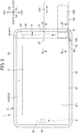
- FIG. 2 is a front view of the portable electronic device 1 of the embodiment.
- FIG. 3 is a partially enlarged view of FIG. 2 .
- FIG. 4 is a partial right-side view of the portable electronic device 1 of the embodiment.
- FIG. 5A is a perspective view showing a reading situation of a card during payment by way of the portable electronic device 1 of the embodiment, showing reading of a magnetic card C1.
- FIG. 5B is a perspective view showing a reading situation of a card during payment by way of the portable electronic device 1 of the embodiment, showing reading of a contact-type IC card C2.
- FIG. 1 is a perspective view showing the portable electronic device 1 of the embodiment of the present invention.
- FIG. 2 is a front view of the portable electronic device 1 of the embodiment.
- FIG. 3 is a partially enlarged view of FIG. 2 .
- FIG. 4 is a partial right-side view of the portable electronic device 1
- FIG. 5C is a perspective view showing a reading situation of a card during payment by way of the portable electronic device 1 of the embodiment, showing reading of a non-contact-type IC card C3.
- FIG. 6 is a cross-sectional view along the line A-A in FIG. 2 .
- FIG. 7 is a cross-sectional view along the line B-B in FIG. 2 .
- the portable electronic device 1 of the embodiment includes a housing 2, a touch panel display unit 3, a magnetic reading unit 4, a contact-type IC reading unit 5, and a non-contact-type reading unit 6.
- the portable electronic device 1 may include general functions as a tablet-type terminal, e.g., a wired communication unit, wireless communication unit, buttons as an input device, speaker, and GPS (Global Positioning System) unit.
- the housing 2 configures an external principle part of the portable electronic device 1, and has a substantially rectangular shape of a flat plate shape.
- the housing 2 includes an oblong, substantially rectangular front surface 21 and back surface 22, top surface 23, bottom surface 24, right surface 25 and left surface 26.
- substantially rectangular in the present specification includes all shapes considered as rectangles in the overall perspective and, for example, also includes a perfect rectangle, rectangles having rounded corners, shapes having sides slightly curved, and the like.
- the housing 2 includes a front cover 210 mainly constituting the front surface 21, a frame 230 mainly constituting the top surface 23, bottom surface 24, right surface 25 and left surface 26, and a rear cover 220 mainly constituting the back surface 22.
- the thickness direction, longitudinal direction and lateral direction are respectively referred to as thickness direction D1, longitudinal direction D2 and lateral direction D3.
- the direction towards the front surface 21 is referred to as forward direction D11
- the direction towards the back surface 22 is referred to as the rear direction D12.
- the direction towards the top surface 23 is referred to as the up direction D21
- the direction towards the bottom surface 24 is referred to as the down direction D22.
- the direction towards the right surface 25 is referred to as the right direction D31
- the direction towards the left surface 26 is referred to as the left direction D32.
- the front cover 210 is configured from a translucent material such as glass or plastic.
- the front cover 210 includes a rectangular transparent display region 211, and an opaque frame region 212 that encircles the four sides of the display region 211.
- the display region 211 and frame region 212 are arranged on the same plane.
- the rear cover 220 is configured by a metallic material such as aluminum alloy or magnesium alloy, for example.
- the front cover 210 and rear cover 220 are arranged in parallel with an interval from each other in the thickness direction D1 of the housing 2.
- the rear cover 220 is arranged on an opposite side in the thickness direction D1 of the housing 2 relative to the front cover 210.
- the frame 230 is provided between the front cover 210 and rear cover 220.
- the frame 230 is configured by a metallic material such as aluminum alloy or magnesium alloy, or a high-rigidity resin, for example.
- High-rigidity resin is a fiber reinforced resin produced by mixing an additive such as glass fiber, carbon fiber, other reinforcing fiber and talc into a resin.
- the frame 230 is continuous in the peripheral direction so as to constitute the top surface 23, bottom surface 24, right surface 25 and left surface 26.
- the touch panel display unit 3 is provided to the front surface 21 of the housing 2.
- the touch panel display unit 3 includes a touch panel and a display unit.
- the touch panel is of piezoelectric-type or electrostatic-type having a contact-type input function.
- the touch panel is fixed by a means such as adhesive to the rear surface side of the display region 211 of the front cover 210.
- the display unit has a substantially rectangular display screen that displays images and pictures in the front surface view of the housing 2.
- the display screen is arranged at the rear surface side of the touch panel.
- the magnetic reading unit 4 performs reading processing of the magnetic card C1.
- the contact-type IC reading unit 5 performs reading processing of the contact-type IC card C2.
- the non-contact-type IC reading unit 6 performs reading processing of the non-contact-type IC card C3.
- the magnetic reading unit 4, contact-type IC reading unit 5 and non-contact-type IC reading unit 6 are integrally configured with the housing 2.
- the magnetic reading unit 4 includes the magnetic sensor 41 and magnet insertion groove 42.
- the magnetic sensor 41 is called a magnet head, and acquires magnetic information from a magnetic recording part of the magnetic card C1.
- the magnet insertion groove 42 is provided in the housing 2 for guiding the magnetic recording part of the magnetic card C1 to the position of the magnetic sensor 41.
- the magnetic sensor 41 is arranged inside of the housing 2 so that the detection part thereof faces the interior of the magnet insertion groove 42.
- the magnet insertion groove 42 extends linearly in the longitudinal direction D2, and opens to the top surface 23 and bottom surface 24. In addition, the magnet insertion groove 42 opens to the right surface 25, and is concave at the bottom in the left direction D32. A bottom part 421 of the magnet insertion groove 42 extends linearly in the longitudinal direction D2.
- the thickness of the magnet insertion groove 42 is slightly thicker than the thickness of the magnetic card C1 (thickness of a region other than an embossing C12 in which the name and card number are punched).
- the magnetic information in the magnetic recording part of the magnetic card C1 is acquired by the magnetic sensor 41.
- the contact-type IC reading unit 5 includes a contact-type IC sensor 51 and an IC insertion groove 52.
- the contact-type IC sensor 51 acquires electronic information from the IC chip by contacting the IC chip of the contact-type IC card C2.
- the IC insertion groove 52 is provided to the housing 2 for guiding the IC chip of the contact-type IC card C2 to the position of the contact-type IC sensor 51.
- the IC insertion groove 52 opens in the right surface 25, and is concaved with a bottom towards the left direction D32.
- a bottom part 521 of the IC insertion groove 52 is positioned more to the left direction D32 than the bottom part 421 of the magnet insertion groove 42.
- the IC insertion groove 52 becomes deeper than the magnet insertion groove 42.
- the bottom part 521 of the IC insertion groove 52 is provided more in an interior region 525 than the bottom part 421 of the magnet insertion groove 42.
- the interior region 525 is a region in the IC insertion groove 52 that is a region more to the interior than the magnet insertion groove 42.
- the contact-type IC sensor 51 is arranged at the interior region 525.
- the contact-type IC sensor 51 is arranged inside of the housing 2 so that the detection unit thereof faces an inner part of the interior region 525 of the IC insertion groove 52.
- the IC insertion groove 52 includes an embossing groove part 522 and a main groove part 523.
- the embossing groove part 522 has a shape corresponding to an embossing C22 of the contact-type IC card C2.
- the main groove part 523 has a shape corresponding to a region C21 other than the embossing C22 of the contact-type IC card C2.
- the thickness of the main groove part 523 is slightly thicker than the thickness of the region C21 other than the embossing C22 of the contact-type IC card C22, and is slight thinner than the thickness of the embossing C22 of the contact-type IC card C2.
- the thickness of the embossing groove part 522 is slightly thicker than the thickness of the embossing C22 of the contact-type IC card C2.
- the contact-type IC card C2 in the IC insertion groove 52, if positioning the embossing C22 of the contact-type IC card C2 in the embossing groove part 522 of the IC insertion groove 52. Then, the contact-type IC card C2 can be made to slide in the left direction D32 without backlash.
- the contact-type IC card C2 When inserted to the interior region 525 of the IC insertion groove 52, the contact-type IC card C2 is retained thereby. The electronic information in the IC chip of the contact-type IC card C2 is thereby acquired by the contact-type IC sensor 51.
- both entrance edges 526 at the entrances of the interior region 525 of the IC insertion groove 52 are rounded (forming R) in the front view.
- the contact-type IC card C2 tends to be guided to the interior region 525.
- the magnetic card C1 will hit the entrance edge 526 (526A) of the interior region 525.
- the entrance edges 526 (526A) are rounded, the magnetic card C1 is hardly obstructed at the entrance edge 526 (526A), and the movement direction of the magnetic card C1 is rectified in the appropriate direction.
- an entrance edge 526B positioned on the upstream side in the movement direction (down direction D22) of the magnetic card C1 may be angular without rounding.
- the magnet insertion groove 42 and IC insertion groove 52 overlap in a portion of these.
- a region more in the right direction D31 than the bottom part 421 of the magnet insertion groove 42 becomes a region in which the magnet insertion groove 42 and IC insertion groove 52 overlap (also referred to as "overlap region 524").
- the non-contact-type IC reading unit 6 includes a non-contact-type IC sensor 61.
- the non-contact-type IC sensor 61 consists of an antenna.
- the non-contact-type IC card C3 includes an IC chip and antenna.
- the non-contact-type IC reading unit 6 acquires electronic information from the IC chip in the non-contact-type IC card C3 arranged in the vicinity of the non-contact-type IC sensor 61 on the side of the front surface 21 of the housing 2.
- a card of the NFC (Near Field Communication) standard can be exemplified.
- the electronic information of the IC chip of the non-contact-type IC card C3 is acquired by the non-contact-type IC sensor 61.
- the magnetic reading unit 4 and contact-type IC reading unit 5 are arranged to the side of one vertical lateral surface (right surface 25) of the housing 2, in a front view of the housing 2.
- the non-contact-type IC reading unit 6 is arranged to the side of another lateral surface (left surface 26) of the housing 2.
- the portable electronic device 1 of the embodiment includes the housing 2 and the touch panel display unit 3 provided to the front surface 21 of the housing 2, along with including the magnetic reading unit 4, contact-type IC reading unit 5 and non-contact-type IC reading unit 6 as reading units that perform reading processing of cards related to payment.
- the magnetic reading unit 4, contact-type IC reading unit 5 and non-contact-type IC reading unit 6 are integrally configured with the housing 2. For this reason, according to the portable electronic device 1 of the embodiment, it is possible provide a tablet-type portable electronic device 1 that can perform payment by cards, as well as being compact.
- the IC reading unit 5 includes the contact-type IC sensor 51 that acquires electronic information from the IC chip of the contact-type IC card C2, and the IC insertion groove 52 provided in the housing 2 for guiding the IC chip of the contact-type IC card C2 to the position of the contact-type IC sensor 51.
- the magnetic reading unit 4 includes the magnetic sensor 41 that acquires magnetic information from the magnetic recording part of the magnetic card C1, and the magnet insertion groove 42 provided in the housing 2 for guiding the magnetic recording part of the magnetic card C1 to the position of the magnetic sensor 41.
- the IC insertion groove 52 and magnetic insertion groove 42 overlap in parts thereof. For this reason, it is possible to achieve space savings of the space (room) of the IC insertion groove 52 and the space (room) of the magnet insertion groove 42.
- the IC insertion groove 52 is provided more to the interior region 525 than the magnetic insertion groove 42.
- the contact-type IC sensor 51 is arranged in the interior region 525. For this reason, it is possible to arrange the contact-type IC sensor 51 at a position not overlapping the magnet insertion groove 42, and thus the degree of freedom in design is high.
- the IC insertion groove 52 includes the embossing groove part 522 having a shape corresponding to the embossing C22 of the contact-type IC card C2. For this reason, during insertion of the contact-type IC card C2 to the IC insertion groove 52, it is possible to apply the embossing groove part 522 as an insertion guide.
- the contact-type IC reading unit 5 and the magnetic reading unit 4 are arranged to a side of the right surface 25, which is the one vertical lateral surface, of the housing 2.
- the non-contact-type IC reading unit 6 is arranged to a side of the left surface 26, which is the other vertical lateral surface, of the housing 2. For this reason, compared to a format in which the contact-type IC reading unit 5, magnetic reading unit 4 and non-contact-type IC reading unit 6 are arranged on the side of the right surface 25, for example, it is easier to achieve a size reduction in the longitudinal direction D2.
- the magnetic reading unit 4, contact-type reading unit 5 and non-contact-type reading unit 6 are included as reading units that perform reading processing of a card related to payment, it is not limited thereto. It is sufficient so long as the portable electronic device includes one or more reading units.
- the magnet insertion groove 42 and the IC insertion groove 52 are concaved in the left direction D32, it is not limited thereto.
- the magnet insertion groove 42 and the IC insertion groove 52 may be concaved to another direction (for example, right direction D31, thickness direction D1, longitudinal direction D2).
- the contact-type IC reading unit 5, magnetic reading unit 4 and non-contact-type reading unit 6 may be arranged on the same side.
Landscapes
- Engineering & Computer Science (AREA)
- Physics & Mathematics (AREA)
- General Physics & Mathematics (AREA)
- Theoretical Computer Science (AREA)
- Business, Economics & Management (AREA)
- Computer Vision & Pattern Recognition (AREA)
- Artificial Intelligence (AREA)
- Accounting & Taxation (AREA)
- Finance (AREA)
- Computer Hardware Design (AREA)
- General Business, Economics & Management (AREA)
- Strategic Management (AREA)
- Human Computer Interaction (AREA)
- General Engineering & Computer Science (AREA)
- Marketing (AREA)
- Development Economics (AREA)
- Economics (AREA)
- Computer Networks & Wireless Communication (AREA)
- Toxicology (AREA)
- Health & Medical Sciences (AREA)
- Microelectronics & Electronic Packaging (AREA)
- Computer Security & Cryptography (AREA)
- Electromagnetism (AREA)
- General Health & Medical Sciences (AREA)
- Telephone Set Structure (AREA)
- Credit Cards Or The Like (AREA)
- Conveying Record Carriers (AREA)
- Casings For Electric Apparatus (AREA)
- Cash Registers Or Receiving Machines (AREA)
- Coin-Freed Apparatuses For Hiring Articles (AREA)
Description
- The present invention relates to a tablet-type portable electronic device having the payment function for cards.
- Tablet-type portable electronic devices have come to be popular (e.g., refer to Patent Document 1). On the other hand, payment terminals dedicated for making payments with various cards (credit cards, cash cards, etc.) consisting of IC cards and magnetic cards are also known (e.g., refer to Patent Document 2).
- Patent Document 1: Japanese Unexamined Patent Application, Publication No.
2012-215682 - Patent Document 2: Japanese Unexamined Patent Application, Publication No.
2013-003810 - A tablet-type portable electronic device that can perform payment by way of a card as well as being compact has been demanded.
- The present invention has an object of providing a tablet-type portable electronic device that can perform payment by way of a card as well as being compact. Means for Solving the Problems
- The present invention is a tablet-type portable electronic device according to
claims 1 to 4. - According to the present invention, it is possible to provide a tablet-type portable electronic device that can perform payment by way of a card, as well as being compact.
-
-
FIG. 1 is a perspective view showing a portableelectronic device 1 of an embodiment of the present invention; -
FIG. 2 is a front view showing the portableelectronic device 1 of the embodiment; -
FIG. 3 is a partially enlarged view ofFIG. 2 ; -
FIG. 4 is a partial right-side view of the portableelectronic device 1 of the embodiment; -
FIG. 5A is a perspective view showing a reading situation of a card during payment by way of the portableelectronic device 1 of the embodiment, showing reading of a magnetic card C1; -
FIG. 5B is a perspective view showing a reading situation of a card during payment by way of the portableelectronic device 1 of the embodiment, showing reading of a contact-type IC card C2; -
FIG. 5C is a perspective view showing a reading situation of a card during payment by way of the portableelectronic device 1 of the embodiment, showing reading of a non-contact-type IC card C3; -
FIG. 6 is a cross-sectional view along the line A-A inFIG. 2 ; and -
FIG. 7 is a cross-sectional view along the line B-B inFIG. 2 . - Hereinafter, a portable
electronic device 1 of an embodiment of the present invention will be explained while referencing the drawings.FIG. 1 is a perspective view showing the portableelectronic device 1 of the embodiment of the present invention.FIG. 2 is a front view of the portableelectronic device 1 of the embodiment.FIG. 3 is a partially enlarged view ofFIG. 2 .FIG. 4 is a partial right-side view of the portableelectronic device 1 of the embodiment.FIG. 5A is a perspective view showing a reading situation of a card during payment by way of the portableelectronic device 1 of the embodiment, showing reading of a magnetic card C1.FIG. 5B is a perspective view showing a reading situation of a card during payment by way of the portableelectronic device 1 of the embodiment, showing reading of a contact-type IC card C2.FIG. 5C is a perspective view showing a reading situation of a card during payment by way of the portableelectronic device 1 of the embodiment, showing reading of a non-contact-type IC card C3.FIG. 6 is a cross-sectional view along the line A-A inFIG. 2 .FIG. 7 is a cross-sectional view along the line B-B inFIG. 2 . - As shown in
FIGS. 1 to 4 , the portableelectronic device 1 of the embodiment includes ahousing 2, a touchpanel display unit 3, amagnetic reading unit 4, a contact-typeIC reading unit 5, and a non-contact-type reading unit 6. The portableelectronic device 1 may include general functions as a tablet-type terminal, e.g., a wired communication unit, wireless communication unit, buttons as an input device, speaker, and GPS (Global Positioning System) unit. - The
housing 2 configures an external principle part of the portableelectronic device 1, and has a substantially rectangular shape of a flat plate shape. Thehousing 2 includes an oblong, substantiallyrectangular front surface 21 andback surface 22,top surface 23,bottom surface 24,right surface 25 andleft surface 26. - It should be noted that "substantially rectangular" in the present specification includes all shapes considered as rectangles in the overall perspective and, for example, also includes a perfect rectangle, rectangles having rounded corners, shapes having sides slightly curved, and the like.
- The
housing 2 includes afront cover 210 mainly constituting thefront surface 21, aframe 230 mainly constituting thetop surface 23,bottom surface 24,right surface 25 andleft surface 26, and arear cover 220 mainly constituting theback surface 22. - In each drawing, the thickness direction, longitudinal direction and lateral direction are respectively referred to as thickness direction D1, longitudinal direction D2 and lateral direction D3. In addition, in the thickness direction D1, the direction towards the
front surface 21 is referred to as forward direction D11, and the direction towards theback surface 22 is referred to as the rear direction D12. In the longitudinal direction D2, the direction towards thetop surface 23 is referred to as the up direction D21, and the direction towards thebottom surface 24 is referred to as the down direction D22. In the lateral direction D3, the direction towards theright surface 25 is referred to as the right direction D31, and the direction towards theleft surface 26 is referred to as the left direction D32. - The
front cover 210 is configured from a translucent material such as glass or plastic. Thefront cover 210 includes a rectangulartransparent display region 211, and anopaque frame region 212 that encircles the four sides of thedisplay region 211. Thedisplay region 211 andframe region 212 are arranged on the same plane. - The
rear cover 220 is configured by a metallic material such as aluminum alloy or magnesium alloy, for example. - The
front cover 210 andrear cover 220 are arranged in parallel with an interval from each other in the thickness direction D1 of thehousing 2. In other words, therear cover 220 is arranged on an opposite side in the thickness direction D1 of thehousing 2 relative to thefront cover 210. - The
frame 230 is provided between thefront cover 210 andrear cover 220. Theframe 230 is configured by a metallic material such as aluminum alloy or magnesium alloy, or a high-rigidity resin, for example. High-rigidity resin is a fiber reinforced resin produced by mixing an additive such as glass fiber, carbon fiber, other reinforcing fiber and talc into a resin. - The
frame 230 is continuous in the peripheral direction so as to constitute thetop surface 23,bottom surface 24,right surface 25 andleft surface 26. - The touch
panel display unit 3 is provided to thefront surface 21 of thehousing 2. The touchpanel display unit 3 includes a touch panel and a display unit. The touch panel is of piezoelectric-type or electrostatic-type having a contact-type input function. The touch panel is fixed by a means such as adhesive to the rear surface side of thedisplay region 211 of thefront cover 210. The display unit has a substantially rectangular display screen that displays images and pictures in the front surface view of thehousing 2. The display screen is arranged at the rear surface side of the touch panel. - As shown in
FIG. 5A , themagnetic reading unit 4 performs reading processing of the magnetic card C1. As shown inFIG. 5B , the contact-typeIC reading unit 5 performs reading processing of the contact-type IC card C2. As shown inFIG. 5C , the non-contact-typeIC reading unit 6 performs reading processing of the non-contact-type IC card C3. - The
magnetic reading unit 4, contact-typeIC reading unit 5 and non-contact-typeIC reading unit 6 are integrally configured with thehousing 2. - As shown in
FIGS. 1 to 6 , themagnetic reading unit 4 includes themagnetic sensor 41 andmagnet insertion groove 42. - The
magnetic sensor 41 is called a magnet head, and acquires magnetic information from a magnetic recording part of the magnetic card C1. Themagnet insertion groove 42 is provided in thehousing 2 for guiding the magnetic recording part of the magnetic card C1 to the position of themagnetic sensor 41. Themagnetic sensor 41 is arranged inside of thehousing 2 so that the detection part thereof faces the interior of themagnet insertion groove 42. - The
magnet insertion groove 42 extends linearly in the longitudinal direction D2, and opens to thetop surface 23 andbottom surface 24. In addition, themagnet insertion groove 42 opens to theright surface 25, and is concave at the bottom in the left direction D32. Abottom part 421 of themagnet insertion groove 42 extends linearly in the longitudinal direction D2. The thickness of the magnet insertion groove 42 (thickness in the thickness direction D1 of the housing 2) is slightly thicker than the thickness of the magnetic card C1 (thickness of a region other than an embossing C12 in which the name and card number are punched). - For this reason, as shown in
FIG. 5A , after inserting the magnetic card C1 in themagnet insertion groove 42, it is possible to slide the magnetic card C1 in the longitudinal direction D2 without backlash. It should be noted that, even if inserting the magnetic card C1 until thebottom part 421 of themagnet insertion groove 42, the embossing C12 of the magnetic card C1 will not be positioned in themagnet insertion groove 42. - By positioning a part of the magnetic card C1 inside of the
magnet insertion groove 42, and moving the magnetic card C1 in the longitudinal direction D2, the magnetic information in the magnetic recording part of the magnetic card C1 is acquired by themagnetic sensor 41. - As shown in
FIGS. 1 to 7 , the contact-typeIC reading unit 5 includes a contact-type IC sensor 51 and anIC insertion groove 52. - The contact-
type IC sensor 51 acquires electronic information from the IC chip by contacting the IC chip of the contact-type IC card C2. TheIC insertion groove 52 is provided to thehousing 2 for guiding the IC chip of the contact-type IC card C2 to the position of the contact-type IC sensor 51. - The
IC insertion groove 52 opens in theright surface 25, and is concaved with a bottom towards the left direction D32. Abottom part 521 of theIC insertion groove 52 is positioned more to the left direction D32 than thebottom part 421 of themagnet insertion groove 42. In other words, in the insertion direction of the contact-type IC card C2 to the IC insertion groove 52 (left direction D32), theIC insertion groove 52 becomes deeper than themagnet insertion groove 42. - That is, in the insertion direction of the contact-type IC card C2 to the IC insertion groove 52 (left direction D32), the
bottom part 521 of theIC insertion groove 52 is provided more in aninterior region 525 than thebottom part 421 of themagnet insertion groove 42. Theinterior region 525 is a region in theIC insertion groove 52 that is a region more to the interior than themagnet insertion groove 42. - The contact-
type IC sensor 51 is arranged at theinterior region 525. In detail, the contact-type IC sensor 51 is arranged inside of thehousing 2 so that the detection unit thereof faces an inner part of theinterior region 525 of theIC insertion groove 52. - As shown in
FIG. 7 , in a right surface view, theIC insertion groove 52 includes anembossing groove part 522 and amain groove part 523. Theembossing groove part 522 has a shape corresponding to an embossing C22 of the contact-type IC card C2. Themain groove part 523 has a shape corresponding to a region C21 other than the embossing C22 of the contact-type IC card C2. - The thickness of the main groove part 523 (thickness in thickness direction D1 of housing 2) is slightly thicker than the thickness of the region C21 other than the embossing C22 of the contact-type IC card C22, and is slight thinner than the thickness of the embossing C22 of the contact-type IC card C2. In addition, the thickness of the embossing groove part 522 (thickness in the thickness direction D1 of the housing 2) is slightly thicker than the thickness of the embossing C22 of the contact-type IC card C2.
- For this reason, it is possible to insert the contact-type IC card C2 in the
IC insertion groove 52, if positioning the embossing C22 of the contact-type IC card C2 in theembossing groove part 522 of theIC insertion groove 52. Then, the contact-type IC card C2 can be made to slide in the left direction D32 without backlash. - When inserted to the
interior region 525 of theIC insertion groove 52, the contact-type IC card C2 is retained thereby. The electronic information in the IC chip of the contact-type IC card C2 is thereby acquired by the contact-type IC sensor 51. - As shown in
FIG. 3 , both entrance edges 526 at the entrances of theinterior region 525 of theIC insertion groove 52 are rounded (forming R) in the front view. Upon inserting the contact-type IC card C2 in theinterior region 525 of theIC insertion groove 52, the contact-type IC card C2 tends to be guided to theinterior region 525. In addition, when the magnetic card C1 is made to slide in themagnet insertion groove 42, even if the magnetic card C1 seems like it will move to theinterior region 525 of theIC insertion groove 52, the magnetic card C1 will hit the entrance edge 526 (526A) of theinterior region 525. Upon doing so, since the entrance edges 526 (526A) are rounded, the magnetic card C1 is hardly obstructed at the entrance edge 526 (526A), and the movement direction of the magnetic card C1 is rectified in the appropriate direction. - It should be noted that, among the two
entrance edges 526 of theinterior region 525, anentrance edge 526B positioned on the upstream side in the movement direction (down direction D22) of the magnetic card C1 may be angular without rounding. - In addition, the
magnet insertion groove 42 andIC insertion groove 52 overlap in a portion of these. In detail, in theIC insertion groove 52, a region more in the right direction D31 than thebottom part 421 of themagnet insertion groove 42 becomes a region in which themagnet insertion groove 42 andIC insertion groove 52 overlap (also referred to as "overlapregion 524"). - As shown in
FIG. 2 , the non-contact-typeIC reading unit 6 includes a non-contact-type IC sensor 61. The non-contact-type IC sensor 61 consists of an antenna. The non-contact-type IC card C3 includes an IC chip and antenna. By sending and receiving data between the antenna of the non-contact-type IC sensor 61 and the antenna of the non-contact-type IC card C3, the non-contact-typeIC reading unit 6 acquires electronic information from the IC chip in the non-contact-type IC card C3 arranged in the vicinity of the non-contact-type IC sensor 61 on the side of thefront surface 21 of thehousing 2. As an example of the non-contact-type IC card C3, a card of the NFC (Near Field Communication) standard can be exemplified. - By causing the non-contact-type IC card C3 to approach the non-contact-type
IC reading unit 6, the electronic information of the IC chip of the non-contact-type IC card C3 is acquired by the non-contact-type IC sensor 61. - In this way, the
magnetic reading unit 4 and contact-typeIC reading unit 5 are arranged to the side of one vertical lateral surface (right surface 25) of thehousing 2, in a front view of thehousing 2. In addition, the non-contact-typeIC reading unit 6 is arranged to the side of another lateral surface (left surface 26) of thehousing 2. - The following effects are exerted according to the portable
electronic device 1 of the embodiment, for example. - The portable
electronic device 1 of the embodiment includes thehousing 2 and the touchpanel display unit 3 provided to thefront surface 21 of thehousing 2, along with including themagnetic reading unit 4, contact-typeIC reading unit 5 and non-contact-typeIC reading unit 6 as reading units that perform reading processing of cards related to payment. Themagnetic reading unit 4, contact-typeIC reading unit 5 and non-contact-typeIC reading unit 6 are integrally configured with thehousing 2. For this reason, according to the portableelectronic device 1 of the embodiment, it is possible provide a tablet-type portableelectronic device 1 that can perform payment by cards, as well as being compact. - In addition, compared to a configuration establishing a separate reading unit (card reader) to be external via a cable, it is possible to avoid skimming from the cable connection portion. In addition, by configuring integrally, it is possible to improve the portability and operability.
- In addition, the
IC reading unit 5 includes the contact-type IC sensor 51 that acquires electronic information from the IC chip of the contact-type IC card C2, and theIC insertion groove 52 provided in thehousing 2 for guiding the IC chip of the contact-type IC card C2 to the position of the contact-type IC sensor 51. Themagnetic reading unit 4 includes themagnetic sensor 41 that acquires magnetic information from the magnetic recording part of the magnetic card C1, and themagnet insertion groove 42 provided in thehousing 2 for guiding the magnetic recording part of the magnetic card C1 to the position of themagnetic sensor 41. TheIC insertion groove 52 andmagnetic insertion groove 42 overlap in parts thereof. For this reason, it is possible to achieve space savings of the space (room) of theIC insertion groove 52 and the space (room) of themagnet insertion groove 42. - In addition, in the insertion direction D32 of the contact-type IC card C2 to the
IC insertion groove 52, theIC insertion groove 52 is provided more to theinterior region 525 than themagnetic insertion groove 42. In addition, the contact-type IC sensor 51 is arranged in theinterior region 525. For this reason, it is possible to arrange the contact-type IC sensor 51 at a position not overlapping themagnet insertion groove 42, and thus the degree of freedom in design is high. - In addition, the
IC insertion groove 52 includes theembossing groove part 522 having a shape corresponding to the embossing C22 of the contact-type IC card C2. For this reason, during insertion of the contact-type IC card C2 to theIC insertion groove 52, it is possible to apply theembossing groove part 522 as an insertion guide. - In addition, in the front view of the portable
electronic device 1, the contact-typeIC reading unit 5 and themagnetic reading unit 4 are arranged to a side of theright surface 25, which is the one vertical lateral surface, of thehousing 2. In addition, the non-contact-typeIC reading unit 6 is arranged to a side of theleft surface 26, which is the other vertical lateral surface, of thehousing 2. For this reason, compared to a format in which the contact-typeIC reading unit 5,magnetic reading unit 4 and non-contact-typeIC reading unit 6 are arranged on the side of theright surface 25, for example, it is easier to achieve a size reduction in the longitudinal direction D2. - Although an ideal embodiment of the present invention is explained in the foregoing, the present invention is not to be limited to the aforementioned embodiment, and can be implemented in various forms.
- For example, in the embodiment, although the
magnetic reading unit 4, contact-type reading unit 5 and non-contact-type reading unit 6 are included as reading units that perform reading processing of a card related to payment, it is not limited thereto. It is sufficient so long as the portable electronic device includes one or more reading units. - In the embodiment, although the
magnet insertion groove 42 and theIC insertion groove 52 are concaved in the left direction D32, it is not limited thereto. Themagnet insertion groove 42 and theIC insertion groove 52 may be concaved to another direction (for example, right direction D31, thickness direction D1, longitudinal direction D2). - The contact-type
IC reading unit 5,magnetic reading unit 4 and non-contact-type reading unit 6 may be arranged on the same side. -
- 1
- portable electronic device
- 2
- housing
- 3
- display unit
- 4
- magnetic reading unit (reading unit)
- 5
- contact-type IC reading unit (reading unit)
- 6
- non-contact-type IC reading unit (reading unit)
- 21
- front surface
- 22
- back surface
- 23
- top surface
- 24
- bottom surface
- 25
- right surface
- 26
- left surface
- 41
- magnetic sensor
- 42
- magnet insertion groove
- 51
- contact-type IC sensor (IC sensor)
- 52
- IC insertion groove
- 61
- non-contact-type IC sensor
- 421
- bottom part
- 521
- bottom part
- 522
- embossing groove part
- 523
- main groove part
- 524
- overlapping region
- 525
- interior region
- 526
- entrance edge
- C1
- magnetic card
- C2
- contact-type IC card
- C22
- embossing
- C3
- non-contact-type IC card
- D1
- thickness direction
- D11
- front direction
- D12
- back direction
- D2
- longitudinal direction
- D21
- up direction
- D22
- down direction
- D3
- lateral direction
- D31
- right direction
- D32
- left direction, insertion direction
Claims (4)
- A tablet-type portable electronic device (1) comprising:a plate-shaped housing (2);a touch panel and display unit (3) provided to a front surface of the housing; anda reading unit that is integrally configured with the housing (2) and performs reading processing of a card related to payment,wherein the housing (2) is substantially rectangular in a front view of the portable electronic device,wherein the portable electric device (1) includes, as the reading unit:characterized in that- a contact-type IC reading unit (5) that performs reading processing of a contact-type IC card (C2) serving as the card, the contact-type IC reading unit (5) having a contact-type IC sensor (51) that acquires electronic information from an IC chip of the contact-type IC card (C2), and an IC insertion groove (52) provided in the housing for guiding the IC chip of the contact-type IC card to a position of the IC sensor, and- a non-contact-type IC reading unit (6) that performs reading processing of a non-contact-type IC card (C3) serving as the card,
the portable electric device (1) further includes, as the reading unit:- a magnetic reading unit (4) that performs reading processing of a magnetic card (C1) serving as the card, the magnetic reading unit (4) including a magnetic sensor (41) that acquires magnetic information from a magnetic recording part of the magnetic card (C1), and a magnetic insertion groove (42) provided in the housing for guiding the magnetic recording part of the magnetic card (C1) to a position of the magnetic sensor (41),wherein the contact-type IC reading unit (5) and the magnetic reading unit (4) are arranged to a side of one vertical lateral surface (25) along a shorter direction of the housing (2), the IC insertion groove (52) and the magnetic insertion groove (42) being open, in said side of said one vertical lateral surface (25) along said shorter direction of the housing (2), to an outer side in a longer direction of the housing and being concaved with a bottom to an inner side in the longer direction, and
wherein the non-contact-type IC reading unit (6) is arranged to a side of the one vertical lateral surface (25) or another vertical lateral surface (26) along the shorter side of the housing (2), and can read a non-contact-type IC card (C3) arranged at the front surface of the housing. - The portable electric device according to claim 1, wherein the IC insertion groove (52) and the magnet insertion groove (42) are overlapping in portions thereof.
- The portable electronic device according to claim 2, wherein a bottom part (521) of the IC insertion groove (52) is provided more in an interior region (525) than a bottom part (421) of the magnet insertion groove (42), in an insertion direction of the IC card to the IC insertion groove, and the contact-type IC sensor (51) is arranged in the interior region.
- The portable electronic device according to any one of claims 1 to 3, wherein the IC insertion groove (52) includes an embossing groove part (522) having a shape corresponding to an embossing (C22) of the IC card.
Priority Applications (1)
| Application Number | Priority Date | Filing Date | Title |
|---|---|---|---|
| EP17167801.4A EP3220313A3 (en) | 2013-07-31 | 2013-11-08 | Portable electronic device |
Applications Claiming Priority (2)
| Application Number | Priority Date | Filing Date | Title |
|---|---|---|---|
| JP2013158474A JP5639236B1 (en) | 2013-07-31 | 2013-07-31 | Portable electronic devices |
| PCT/JP2013/080355 WO2015015661A1 (en) | 2013-07-31 | 2013-11-08 | Portable electronic apparatus |
Related Child Applications (1)
| Application Number | Title | Priority Date | Filing Date |
|---|---|---|---|
| EP17167801.4A Division EP3220313A3 (en) | 2013-07-31 | 2013-11-08 | Portable electronic device |
Publications (3)
| Publication Number | Publication Date |
|---|---|
| EP2919168A1 EP2919168A1 (en) | 2015-09-16 |
| EP2919168A4 EP2919168A4 (en) | 2016-03-09 |
| EP2919168B1 true EP2919168B1 (en) | 2017-04-26 |
Family
ID=52145673
Family Applications (2)
| Application Number | Title | Priority Date | Filing Date |
|---|---|---|---|
| EP13890788.6A Not-in-force EP2919168B1 (en) | 2013-07-31 | 2013-11-08 | Portable electronic apparatus |
| EP17167801.4A Withdrawn EP3220313A3 (en) | 2013-07-31 | 2013-11-08 | Portable electronic device |
Family Applications After (1)
| Application Number | Title | Priority Date | Filing Date |
|---|---|---|---|
| EP17167801.4A Withdrawn EP3220313A3 (en) | 2013-07-31 | 2013-11-08 | Portable electronic device |
Country Status (16)
| Country | Link |
|---|---|
| US (3) | US9323961B2 (en) |
| EP (2) | EP2919168B1 (en) |
| JP (1) | JP5639236B1 (en) |
| KR (2) | KR20160026971A (en) |
| CN (1) | CN105190648A (en) |
| AU (2) | AU2013395851B2 (en) |
| BR (1) | BR212016000904Y1 (en) |
| CA (2) | CA2916457A1 (en) |
| HK (1) | HK1212493A1 (en) |
| MX (1) | MX2016001150A (en) |
| RU (3) | RU2604327C1 (en) |
| SA (1) | SA515370339B1 (en) |
| SG (1) | SG11201506204PA (en) |
| TW (3) | TWI537836B (en) |
| WO (1) | WO2015015661A1 (en) |
| ZA (2) | ZA201600181B (en) |
Families Citing this family (22)
| Publication number | Priority date | Publication date | Assignee | Title |
|---|---|---|---|---|
| JP5849194B1 (en) | 2014-07-31 | 2016-01-27 | パナソニックIpマネジメント株式会社 | Information processing apparatus and transaction terminal apparatus |
| FR3039297B1 (en) | 2015-07-20 | 2018-05-18 | Roam Data, Inc | COMPACT CARD READER |
| US10044710B2 (en) | 2016-02-22 | 2018-08-07 | Bpip Limited Liability Company | Device and method for validating a user using an intelligent voice print |
| CN107293856B (en) * | 2016-03-31 | 2020-11-10 | 宇龙计算机通信科技(深圳)有限公司 | NFC antenna structure and mobile terminal |
| JP6042017B1 (en) * | 2016-06-24 | 2016-12-14 | 佳弘 東 | Electronics |
| US10430783B2 (en) | 2016-10-03 | 2019-10-01 | Square, Inc. | Transmit phase detection circuit |
| USD812130S1 (en) * | 2016-10-28 | 2018-03-06 | Square, Inc. | Electronic device |
| USD811472S1 (en) | 2016-10-28 | 2018-02-27 | Square, Inc. | Electronic device |
| USD810816S1 (en) | 2016-10-28 | 2018-02-20 | Square, Inc. | Electronic device |
| USD829274S1 (en) * | 2017-04-10 | 2018-09-25 | Pax Computer Technology (Shenzhen) Co., Ltd. | Payment terminal |
| USD844696S1 (en) * | 2017-09-28 | 2019-04-02 | Clover Network, Inc. | Tablet with card reader |
| USD851697S1 (en) * | 2017-12-04 | 2019-06-18 | Clover Network, Inc. | Tablet |
| TWD192495S (en) * | 2018-01-15 | 2018-08-21 | 廣達電腦股份有限公司 | Terminal |
| TWD192496S (en) * | 2018-01-15 | 2018-08-21 | 廣達電腦股份有限公司 | Terminal |
| USD886898S1 (en) * | 2018-11-23 | 2020-06-09 | Fujian Landi Commercial Equipment Co., Ltd. | Mobile payment terminal |
| TWD198625S (en) * | 2018-12-05 | 2019-07-11 | 廣達電腦股份有限公司 | Point of sale machine |
| CN113343721B (en) * | 2020-03-02 | 2024-06-11 | 神讯电脑(昆山)有限公司 | Mobile electronic device |
| USD957514S1 (en) * | 2020-06-17 | 2022-07-12 | Shopify Inc. | Point of sale device |
| USD941911S1 (en) * | 2020-07-01 | 2022-01-25 | Pax Computer Technology (Shenzhen) Co., Ltd. | Mobile payment terminal |
| USD1024181S1 (en) * | 2021-04-14 | 2024-04-23 | Pax Computer Technology (Shenzhen) Co., Ltd. | Payment POS machine |
| USD994667S1 (en) * | 2021-12-28 | 2023-08-08 | Shenzhen Wang An Technology Co., Ltd. | Card reader |
| USD1034799S1 (en) * | 2022-12-29 | 2024-07-09 | Banks And Acquirers International Holding | Payment terminal |
Family Cites Families (29)
| Publication number | Priority date | Publication date | Assignee | Title |
|---|---|---|---|---|
| JPS6476379A (en) * | 1987-09-18 | 1989-03-22 | Matsushita Electric Ind Co Ltd | Magnetic and ic card reader/writer |
| JP2841591B2 (en) * | 1989-12-19 | 1998-12-24 | オムロン株式会社 | Card reader |
| EP0492358A1 (en) | 1990-12-21 | 1992-07-01 | Tandem Computers Incorporated | Electronic terminal and method for encoding magnetic strip and IC data cards |
| JP2957174B1 (en) * | 1998-08-27 | 1999-10-04 | 三菱電機株式会社 | IC card connector |
| FR2789786B1 (en) * | 1999-02-12 | 2001-04-27 | Ascom Monetel Sa | PAYMENT TERMINAL ACCEPTING CONTACTLESS CARD PAYMENTS |
| DE60127468T2 (en) | 2000-01-24 | 2008-01-31 | Nidec Sankyo Corp. | Manual chip card reader |
| JP3671881B2 (en) * | 2001-07-18 | 2005-07-13 | ソニー株式会社 | COMMUNICATION SYSTEM AND METHOD, INFORMATION PROCESSING DEVICE AND METHOD, COMMUNICATION TERMINAL AND METHOD, EXPANSION DEVICE, AND PROGRAM |
| CN1177292C (en) * | 2001-12-30 | 2004-11-24 | 深圳旭东精工有限公司 | Multifunctional antifraud reader-writer |
| JP3631725B2 (en) * | 2002-03-19 | 2005-03-23 | 東芝テック株式会社 | Self-checkout device |
| CN1558364A (en) * | 2004-01-17 | 2004-12-29 | 江正昌 | Multifunctional IC card reader writer for mobile phone |
| CN2696047Y (en) | 2004-02-16 | 2005-04-27 | 江正昌 | Multifunctional IC card reader of mobile phone |
| US7059520B1 (en) | 2005-03-17 | 2006-06-13 | Joel Shtesl | Universal credit card integrated with cellular telephone |
| JP4596518B2 (en) * | 2004-06-25 | 2010-12-08 | 株式会社ダンレイ | Hot water mixing valve |
| JP2006099599A (en) * | 2004-09-30 | 2006-04-13 | Matsushita Electric Ind Co Ltd | Mobile settlement terminal |
| CN101276448A (en) | 2007-03-29 | 2008-10-01 | 阿里巴巴集团控股有限公司 | Payment system and method performing trading with identification card including IC card |
| FR2926150B1 (en) * | 2008-01-09 | 2010-06-04 | Siemens Sas | CONTROL MODULE FOR ONBOARD COMPUTING TERMINAL. |
| KR200452626Y1 (en) * | 2008-08-26 | 2011-03-09 | 한국정보통신주식회사 | Portable Terminal Device with Conner Type Multiple Card Reader |
| JP2011166275A (en) * | 2010-02-05 | 2011-08-25 | Denso Wave Inc | Foldable mobile terminal |
| WO2012094301A1 (en) * | 2011-01-03 | 2012-07-12 | Schwarzkopf Aron | Apparatus and systems of a computerized bill presenter system |
| JP5738008B2 (en) | 2011-03-03 | 2015-06-17 | キヤノン電子株式会社 | Portable payment terminal |
| JP5161992B2 (en) | 2011-03-31 | 2013-03-13 | 株式会社東芝 | Electronics |
| JP5688563B2 (en) | 2011-06-16 | 2015-03-25 | パナソニックIpマネジメント株式会社 | Card reader |
| RU118140U1 (en) * | 2012-02-10 | 2012-07-10 | Владимир Александрович Елин | PERSONAL ELECTRONIC COMMUNICATOR |
| GB2499431A (en) * | 2012-02-16 | 2013-08-21 | Mobipaypoint Uk Ltd | Hybrid payment terminal with viewing window for CVV code |
| KR20140028609A (en) * | 2012-08-29 | 2014-03-10 | 주식회사 케이티 | Apparatus for card payment using mobile terminal |
| USD681639S1 (en) | 2012-12-14 | 2013-05-07 | Google Inc. | Tablet enclosure credit card reader |
| US8856033B2 (en) * | 2013-03-01 | 2014-10-07 | Retail Technologies Corporation | Mobile barcode scanner gun system with mobile tablet device having a mobile POS and enterprise resource planning application for customer checkout/order fulfillment and real time in store inventory management for retail establishment |
| NZ714493A (en) * | 2013-05-16 | 2020-05-29 | Mobelisk Group Llc | Modular tablet case |
| US10558958B2 (en) * | 2013-05-17 | 2020-02-11 | Visa International Service Association | Contactless message transmission |
-
2013
- 2013-07-31 JP JP2013158474A patent/JP5639236B1/en not_active Expired - Fee Related
- 2013-11-08 WO PCT/JP2013/080355 patent/WO2015015661A1/en active Application Filing
- 2013-11-08 CN CN201380074444.3A patent/CN105190648A/en active Pending
- 2013-11-08 KR KR1020167000300A patent/KR20160026971A/en not_active Application Discontinuation
- 2013-11-08 CA CA2916457A patent/CA2916457A1/en not_active Abandoned
- 2013-11-08 US US14/649,814 patent/US9323961B2/en not_active Expired - Fee Related
- 2013-11-08 CA CA2896651A patent/CA2896651C/en active Active
- 2013-11-08 BR BR212016000904-0U patent/BR212016000904Y1/en active IP Right Grant
- 2013-11-08 MX MX2016001150A patent/MX2016001150A/en unknown
- 2013-11-08 RU RU2016104989/08A patent/RU2604327C1/en active
- 2013-11-08 SG SG11201506204PA patent/SG11201506204PA/en unknown
- 2013-11-08 RU RU2016141943A patent/RU2016141943A/en not_active Application Discontinuation
- 2013-11-08 AU AU2013395851A patent/AU2013395851B2/en active Active
- 2013-11-08 KR KR1020157021100A patent/KR101586982B1/en active Application Filing
- 2013-11-08 EP EP13890788.6A patent/EP2919168B1/en not_active Not-in-force
- 2013-11-08 EP EP17167801.4A patent/EP3220313A3/en not_active Withdrawn
- 2013-11-08 RU RU2016141942A patent/RU2016141942A/en not_active Application Discontinuation
- 2013-12-24 TW TW102147865A patent/TWI537836B/en not_active IP Right Cessation
- 2013-12-24 TW TW105113828A patent/TWI578238B/en active
- 2013-12-24 TW TW106103677A patent/TW201721525A/en unknown
-
2015
- 2015-10-27 SA SA515370339A patent/SA515370339B1/en unknown
-
2016
- 2016-01-06 HK HK16100088.5A patent/HK1212493A1/en unknown
- 2016-01-11 AU AU2016200140A patent/AU2016200140A1/en not_active Abandoned
- 2016-01-11 ZA ZA2016/00181A patent/ZA201600181B/en unknown
- 2016-01-13 US US14/995,056 patent/US9569645B2/en active Active
-
2017
- 2017-02-13 US US15/431,137 patent/US20170154196A1/en not_active Abandoned
- 2017-04-20 ZA ZA2017/02593A patent/ZA201702593B/en unknown
Also Published As
Similar Documents
| Publication | Publication Date | Title |
|---|---|---|
| EP2919168B1 (en) | Portable electronic apparatus | |
| CN113037899B (en) | Flexible display device | |
| EP3096433A1 (en) | Wireless charging pad, wireless charging device, and electronic device using the same | |
| CN111434094B (en) | Electronic device with full display | |
| EP2518696B1 (en) | Travel kiosk | |
| JP6144721B2 (en) | Portable electronic devices | |
| JP2015146220A (en) | Portable electronic apparatus | |
| JP2015043241A (en) | Portable electronic device | |
| JP2015032322A (en) | Portable electronic device | |
| BR122016003864A2 (en) | portable electronic device | |
| JP6042017B1 (en) | Electronics | |
| KR101917682B1 (en) | Terminal | |
| WO2017221958A1 (en) | Electronic device |
Legal Events
| Date | Code | Title | Description |
|---|---|---|---|
| PUAI | Public reference made under article 153(3) epc to a published international application that has entered the european phase |
Free format text: ORIGINAL CODE: 0009012 |
|
| 17P | Request for examination filed |
Effective date: 20150610 |
|
| AK | Designated contracting states |
Kind code of ref document: A1 Designated state(s): AL AT BE BG CH CY CZ DE DK EE ES FI FR GB GR HR HU IE IS IT LI LT LU LV MC MK MT NL NO PL PT RO RS SE SI SK SM TR |
|
| AX | Request for extension of the european patent |
Extension state: BA ME |
|
| RA4 | Supplementary search report drawn up and despatched (corrected) |
Effective date: 20160208 |
|
| RIC1 | Information provided on ipc code assigned before grant |
Ipc: G06K 7/00 20060101ALI20160202BHEP Ipc: G06F 1/16 20060101ALI20160202BHEP Ipc: G06K 7/08 20060101ALI20160202BHEP Ipc: G06K 17/00 20060101AFI20160202BHEP |
|
| DAX | Request for extension of the european patent (deleted) | ||
| GRAP | Despatch of communication of intention to grant a patent |
Free format text: ORIGINAL CODE: EPIDOSNIGR1 |
|
| INTG | Intention to grant announced |
Effective date: 20161111 |
|
| GRAS | Grant fee paid |
Free format text: ORIGINAL CODE: EPIDOSNIGR3 |
|
| GRAA | (expected) grant |
Free format text: ORIGINAL CODE: 0009210 |
|
| AK | Designated contracting states |
Kind code of ref document: B1 Designated state(s): AL AT BE BG CH CY CZ DE DK EE ES FI FR GB GR HR HU IE IS IT LI LT LU LV MC MK MT NL NO PL PT RO RS SE SI SK SM TR |
|
| REG | Reference to a national code |
Ref country code: GB Ref legal event code: FG4D |
|
| REG | Reference to a national code |
Ref country code: CH Ref legal event code: EP |
|
| REG | Reference to a national code |
Ref country code: AT Ref legal event code: REF Ref document number: 888462 Country of ref document: AT Kind code of ref document: T Effective date: 20170515 |
|
| REG | Reference to a national code |
Ref country code: IE Ref legal event code: FG4D |
|
| REG | Reference to a national code |
Ref country code: DE Ref legal event code: R096 Ref document number: 602013020470 Country of ref document: DE |
|
| REG | Reference to a national code |
Ref country code: NL Ref legal event code: MP Effective date: 20170426 |
|
| REG | Reference to a national code |
Ref country code: LT Ref legal event code: MG4D |
|
| REG | Reference to a national code |
Ref country code: AT Ref legal event code: MK05 Ref document number: 888462 Country of ref document: AT Kind code of ref document: T Effective date: 20170426 |
|
| PG25 | Lapsed in a contracting state [announced via postgrant information from national office to epo] |
Ref country code: NL Free format text: LAPSE BECAUSE OF FAILURE TO SUBMIT A TRANSLATION OF THE DESCRIPTION OR TO PAY THE FEE WITHIN THE PRESCRIBED TIME-LIMIT Effective date: 20170426 |
|
| PG25 | Lapsed in a contracting state [announced via postgrant information from national office to epo] |
Ref country code: FI Free format text: LAPSE BECAUSE OF FAILURE TO SUBMIT A TRANSLATION OF THE DESCRIPTION OR TO PAY THE FEE WITHIN THE PRESCRIBED TIME-LIMIT Effective date: 20170426 Ref country code: AT Free format text: LAPSE BECAUSE OF FAILURE TO SUBMIT A TRANSLATION OF THE DESCRIPTION OR TO PAY THE FEE WITHIN THE PRESCRIBED TIME-LIMIT Effective date: 20170426 Ref country code: GR Free format text: LAPSE BECAUSE OF FAILURE TO SUBMIT A TRANSLATION OF THE DESCRIPTION OR TO PAY THE FEE WITHIN THE PRESCRIBED TIME-LIMIT Effective date: 20170727 Ref country code: LT Free format text: LAPSE BECAUSE OF FAILURE TO SUBMIT A TRANSLATION OF THE DESCRIPTION OR TO PAY THE FEE WITHIN THE PRESCRIBED TIME-LIMIT Effective date: 20170426 Ref country code: NO Free format text: LAPSE BECAUSE OF FAILURE TO SUBMIT A TRANSLATION OF THE DESCRIPTION OR TO PAY THE FEE WITHIN THE PRESCRIBED TIME-LIMIT Effective date: 20170726 Ref country code: HR Free format text: LAPSE BECAUSE OF FAILURE TO SUBMIT A TRANSLATION OF THE DESCRIPTION OR TO PAY THE FEE WITHIN THE PRESCRIBED TIME-LIMIT Effective date: 20170426 Ref country code: ES Free format text: LAPSE BECAUSE OF FAILURE TO SUBMIT A TRANSLATION OF THE DESCRIPTION OR TO PAY THE FEE WITHIN THE PRESCRIBED TIME-LIMIT Effective date: 20170426 |
|
| PG25 | Lapsed in a contracting state [announced via postgrant information from national office to epo] |
Ref country code: SE Free format text: LAPSE BECAUSE OF FAILURE TO SUBMIT A TRANSLATION OF THE DESCRIPTION OR TO PAY THE FEE WITHIN THE PRESCRIBED TIME-LIMIT Effective date: 20170426 Ref country code: LV Free format text: LAPSE BECAUSE OF FAILURE TO SUBMIT A TRANSLATION OF THE DESCRIPTION OR TO PAY THE FEE WITHIN THE PRESCRIBED TIME-LIMIT Effective date: 20170426 Ref country code: BG Free format text: LAPSE BECAUSE OF FAILURE TO SUBMIT A TRANSLATION OF THE DESCRIPTION OR TO PAY THE FEE WITHIN THE PRESCRIBED TIME-LIMIT Effective date: 20170726 Ref country code: IS Free format text: LAPSE BECAUSE OF FAILURE TO SUBMIT A TRANSLATION OF THE DESCRIPTION OR TO PAY THE FEE WITHIN THE PRESCRIBED TIME-LIMIT Effective date: 20170826 Ref country code: RS Free format text: LAPSE BECAUSE OF FAILURE TO SUBMIT A TRANSLATION OF THE DESCRIPTION OR TO PAY THE FEE WITHIN THE PRESCRIBED TIME-LIMIT Effective date: 20170426 Ref country code: PL Free format text: LAPSE BECAUSE OF FAILURE TO SUBMIT A TRANSLATION OF THE DESCRIPTION OR TO PAY THE FEE WITHIN THE PRESCRIBED TIME-LIMIT Effective date: 20170426 |
|
| REG | Reference to a national code |
Ref country code: DE Ref legal event code: R097 Ref document number: 602013020470 Country of ref document: DE |
|
| PG25 | Lapsed in a contracting state [announced via postgrant information from national office to epo] |
Ref country code: RO Free format text: LAPSE BECAUSE OF FAILURE TO SUBMIT A TRANSLATION OF THE DESCRIPTION OR TO PAY THE FEE WITHIN THE PRESCRIBED TIME-LIMIT Effective date: 20170426 Ref country code: CZ Free format text: LAPSE BECAUSE OF FAILURE TO SUBMIT A TRANSLATION OF THE DESCRIPTION OR TO PAY THE FEE WITHIN THE PRESCRIBED TIME-LIMIT Effective date: 20170426 Ref country code: DK Free format text: LAPSE BECAUSE OF FAILURE TO SUBMIT A TRANSLATION OF THE DESCRIPTION OR TO PAY THE FEE WITHIN THE PRESCRIBED TIME-LIMIT Effective date: 20170426 Ref country code: SK Free format text: LAPSE BECAUSE OF FAILURE TO SUBMIT A TRANSLATION OF THE DESCRIPTION OR TO PAY THE FEE WITHIN THE PRESCRIBED TIME-LIMIT Effective date: 20170426 Ref country code: EE Free format text: LAPSE BECAUSE OF FAILURE TO SUBMIT A TRANSLATION OF THE DESCRIPTION OR TO PAY THE FEE WITHIN THE PRESCRIBED TIME-LIMIT Effective date: 20170426 |
|
| PG25 | Lapsed in a contracting state [announced via postgrant information from national office to epo] |
Ref country code: IT Free format text: LAPSE BECAUSE OF FAILURE TO SUBMIT A TRANSLATION OF THE DESCRIPTION OR TO PAY THE FEE WITHIN THE PRESCRIBED TIME-LIMIT Effective date: 20170426 Ref country code: SM Free format text: LAPSE BECAUSE OF FAILURE TO SUBMIT A TRANSLATION OF THE DESCRIPTION OR TO PAY THE FEE WITHIN THE PRESCRIBED TIME-LIMIT Effective date: 20170426 |
|
| PLBE | No opposition filed within time limit |
Free format text: ORIGINAL CODE: 0009261 |
|
| STAA | Information on the status of an ep patent application or granted ep patent |
Free format text: STATUS: NO OPPOSITION FILED WITHIN TIME LIMIT |
|
| 26N | No opposition filed |
Effective date: 20180129 |
|
| PG25 | Lapsed in a contracting state [announced via postgrant information from national office to epo] |
Ref country code: SI Free format text: LAPSE BECAUSE OF FAILURE TO SUBMIT A TRANSLATION OF THE DESCRIPTION OR TO PAY THE FEE WITHIN THE PRESCRIBED TIME-LIMIT Effective date: 20170426 |
|
| REG | Reference to a national code |
Ref country code: DE Ref legal event code: R119 Ref document number: 602013020470 Country of ref document: DE |
|
| PG25 | Lapsed in a contracting state [announced via postgrant information from national office to epo] |
Ref country code: MC Free format text: LAPSE BECAUSE OF FAILURE TO SUBMIT A TRANSLATION OF THE DESCRIPTION OR TO PAY THE FEE WITHIN THE PRESCRIBED TIME-LIMIT Effective date: 20170426 |
|
| GBPC | Gb: european patent ceased through non-payment of renewal fee |
Effective date: 20171108 |
|
| PG25 | Lapsed in a contracting state [announced via postgrant information from national office to epo] |
Ref country code: CH Free format text: LAPSE BECAUSE OF NON-PAYMENT OF DUE FEES Effective date: 20171130 Ref country code: LI Free format text: LAPSE BECAUSE OF NON-PAYMENT OF DUE FEES Effective date: 20171130 |
|
| PG25 | Lapsed in a contracting state [announced via postgrant information from national office to epo] |
Ref country code: LU Free format text: LAPSE BECAUSE OF NON-PAYMENT OF DUE FEES Effective date: 20171108 |
|
| REG | Reference to a national code |
Ref country code: FR Ref legal event code: ST Effective date: 20180731 Ref country code: BE Ref legal event code: MM Effective date: 20171130 |
|
| REG | Reference to a national code |
Ref country code: IE Ref legal event code: MM4A |
|
| PG25 | Lapsed in a contracting state [announced via postgrant information from national office to epo] |
Ref country code: MT Free format text: LAPSE BECAUSE OF NON-PAYMENT OF DUE FEES Effective date: 20171108 |
|
| PG25 | Lapsed in a contracting state [announced via postgrant information from national office to epo] |
Ref country code: IE Free format text: LAPSE BECAUSE OF NON-PAYMENT OF DUE FEES Effective date: 20171108 Ref country code: FR Free format text: LAPSE BECAUSE OF NON-PAYMENT OF DUE FEES Effective date: 20171130 Ref country code: DE Free format text: LAPSE BECAUSE OF NON-PAYMENT OF DUE FEES Effective date: 20180602 |
|
| PG25 | Lapsed in a contracting state [announced via postgrant information from national office to epo] |
Ref country code: BE Free format text: LAPSE BECAUSE OF NON-PAYMENT OF DUE FEES Effective date: 20171130 Ref country code: GB Free format text: LAPSE BECAUSE OF NON-PAYMENT OF DUE FEES Effective date: 20171108 |
|
| PG25 | Lapsed in a contracting state [announced via postgrant information from national office to epo] |
Ref country code: HU Free format text: LAPSE BECAUSE OF FAILURE TO SUBMIT A TRANSLATION OF THE DESCRIPTION OR TO PAY THE FEE WITHIN THE PRESCRIBED TIME-LIMIT; INVALID AB INITIO Effective date: 20131108 |
|
| PG25 | Lapsed in a contracting state [announced via postgrant information from national office to epo] |
Ref country code: CY Free format text: LAPSE BECAUSE OF FAILURE TO SUBMIT A TRANSLATION OF THE DESCRIPTION OR TO PAY THE FEE WITHIN THE PRESCRIBED TIME-LIMIT Effective date: 20170426 |
|
| PG25 | Lapsed in a contracting state [announced via postgrant information from national office to epo] |
Ref country code: MK Free format text: LAPSE BECAUSE OF FAILURE TO SUBMIT A TRANSLATION OF THE DESCRIPTION OR TO PAY THE FEE WITHIN THE PRESCRIBED TIME-LIMIT Effective date: 20170426 |
|
| PG25 | Lapsed in a contracting state [announced via postgrant information from national office to epo] |
Ref country code: TR Free format text: LAPSE BECAUSE OF FAILURE TO SUBMIT A TRANSLATION OF THE DESCRIPTION OR TO PAY THE FEE WITHIN THE PRESCRIBED TIME-LIMIT Effective date: 20170426 |
|
| PG25 | Lapsed in a contracting state [announced via postgrant information from national office to epo] |
Ref country code: PT Free format text: LAPSE BECAUSE OF FAILURE TO SUBMIT A TRANSLATION OF THE DESCRIPTION OR TO PAY THE FEE WITHIN THE PRESCRIBED TIME-LIMIT Effective date: 20170426 |
|
| PG25 | Lapsed in a contracting state [announced via postgrant information from national office to epo] |
Ref country code: AL Free format text: LAPSE BECAUSE OF FAILURE TO SUBMIT A TRANSLATION OF THE DESCRIPTION OR TO PAY THE FEE WITHIN THE PRESCRIBED TIME-LIMIT Effective date: 20170426 |