JP2015043241A - Portable electronic device - Google Patents
Portable electronic device Download PDFInfo
- Publication number
- JP2015043241A JP2015043241A JP2014244273A JP2014244273A JP2015043241A JP 2015043241 A JP2015043241 A JP 2015043241A JP 2014244273 A JP2014244273 A JP 2014244273A JP 2014244273 A JP2014244273 A JP 2014244273A JP 2015043241 A JP2015043241 A JP 2015043241A
- Authority
- JP
- Japan
- Prior art keywords
- magnetic
- card
- insertion groove
- contact
- type
- Prior art date
- Legal status (The legal status is an assumption and is not a legal conclusion. Google has not performed a legal analysis and makes no representation as to the accuracy of the status listed.)
- Pending
Links
Images


Abstract
Description
本発明は、カードの決済機能を有するタブレット型の携帯電子機器に関する。 The present invention relates to a tablet-type portable electronic device having a card settlement function.
タブレット型の携帯電子機器が普及してきている(例えば、特許文献1参照)。一方、ICカードや磁気カードからなる各種カード(クレジットカード、キャッシュカード等)を決済するための専用の決済端末も知られている(例えば、特許文献2参照)。 Tablet-type portable electronic devices have become widespread (for example, see Patent Document 1). On the other hand, a dedicated payment terminal for paying various cards (credit card, cash card, etc.) made of an IC card or a magnetic card is also known (for example, see Patent Document 2).
カードによる決済を行うことができると共にコンパクトなタブレット型の携帯電子機器が望まれている。 There is a demand for a compact tablet-type portable electronic device that can perform settlement by card.
本発明は、カードによる決済を行うことができると共にコンパクトなタブレット型の携帯電子機器を提供することを目的とする。 SUMMARY OF THE INVENTION An object of the present invention is to provide a compact tablet-type portable electronic device that can perform settlement using a card.
本発明は、板状の筐体と、前記筐体の前面に設けられるタッチパネル及び表示部と、決済に係るカードの読み取り処理を行う読み取り部と、を備え、前記読み取り部は、前記筐体と一体的に構成されているタブレット型の携帯電子機器である。 The present invention includes a plate-shaped housing, a touch panel and a display unit provided on the front surface of the housing, and a reading unit that performs a card reading process related to payment, and the reading unit includes the housing and the housing. It is a tablet-type portable electronic device configured integrally.
また、前記読み取り部は、前記カードとしてのICカードの読み取り処理を行うIC読み取り部と、前記カードとしての磁気カードの読み取り処理を行う磁気読み取り部と、を備え、前記IC読み取り部は、ICカードのICチップから電子情報を取得するICセンサと、ICカードのICチップを前記ICセンサの位置に誘導するために前記筐体に設けられるIC用挿入溝と、を備え、前記磁気読み取り部は、磁気カードの磁気記録部から磁気情報を取得する磁気センサと、磁気カードの磁気記録部を前記磁気センサの位置に誘導するために前記筐体に設けられる磁気用挿入溝と、を備え、前記IC用挿入溝と前記磁気用挿入溝とは、それらの一部において重複していてもよい。 The reading unit includes an IC reading unit that performs reading processing of an IC card as the card, and a magnetic reading unit that performs reading processing of a magnetic card as the card, and the IC reading unit includes an IC card An IC sensor that obtains electronic information from the IC chip, and an IC insertion groove provided in the housing for guiding the IC chip of the IC card to the position of the IC sensor, and the magnetic reading unit includes: A magnetic sensor for acquiring magnetic information from a magnetic recording part of the magnetic card; and a magnetic insertion groove provided in the housing for guiding the magnetic recording part of the magnetic card to the position of the magnetic sensor, the IC The magnetic insertion groove and the magnetic insertion groove may overlap with each other.
また、前記IC用挿入溝へのICカードの挿入方向において、前記IC用挿入溝の底部は、前記磁気用挿入溝の底部よりも奥の領域に設けられており、前記ICセンサは、前記奥の領域に配置されていてもよい。 In addition, in the insertion direction of the IC card into the IC insertion groove, the bottom of the IC insertion groove is provided in a region deeper than the bottom of the magnetic insertion groove, and the IC sensor It may be arranged in the area.
また、前記IC用挿入溝は、ICカードのエンボス部に対応する形状を有するエンボス部用溝部を備えていてもよい。 The IC insertion groove may include an embossing groove having a shape corresponding to the embossing of the IC card.
また、前記IC読み取り部は、前記ICカードとしての接触型ICカードの読み取り処理を行う接触型IC読み取り部と、前記ICカードとしての非接触型ICカードの読み取り処理を行う非接触型IC読み取り部と、を備えていてもよい。 The IC reading unit includes a contact type IC reading unit that performs a reading process of a contact type IC card as the IC card, and a non-contact type IC reading unit that performs a reading process of the non-contact type IC card as the IC card. And may be provided.
また、前記筐体及び前記表示部は、前記携帯電子機器の前面視において略矩形であり、
前記接触型IC読み取り部及び前記磁気読み取り部は、前記筐体における一方の縦側面の側に配置されていると共に、前記非接触型IC読み取り部は、前記筐体における他方の縦側面の側に配置されていてもよい。
Further, the casing and the display unit are substantially rectangular in a front view of the portable electronic device,
The contact type IC reading unit and the magnetic reading unit are arranged on one vertical side surface side of the casing, and the non-contact type IC reading unit is arranged on the other vertical side surface side of the casing. It may be arranged.
本発明によれば、カードによる決済を行うことができると共にコンパクトなタブレット型の携帯電子機器を提供することができる。 ADVANTAGE OF THE INVENTION According to this invention, while being able to perform payment with a card | curd, a compact tablet-type portable electronic device can be provided.
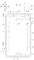
以下、本発明の実施形態の携帯電子機器1について、図面を参照しながら説明する。図1は、本発明の実施形態の携帯電子機器1を示す斜視図である。図2は、実施形態の携帯電子機器1の正面図である。図3は、図2の部分拡大図である。図4は、実施形態の携帯電子機器1の部分的な右側面図である。図5は、実施形態の携帯電子機器1による決済時におけるカードの読み取り態様を示す斜視図であり、(A)は磁気カードC1の読み取り、(B)は接触型ICカードC2の読み取り、(C)は非接触型ICカードC3の読み取りを示す。図6は、図2に示すA−A線断面図である。図7は、図2に示すB−B線断面図である。
Hereinafter, a portable
図1〜図4に示すように、実施形態の携帯電子機器1は、筐体2と、タッチパネル・表示部3と、磁気読み取り部4と、接触型IC読み取り部5と、非接触型IC読み取り部6と、を備える。携帯電子機器1は、タブレット型端末として一般的な機能、例えば、有線通信部、無線通信部、入力装置としてのボタン、スピーカ、GPS(Global Positioning System、全地球測位システム)部を備えていてもよい。
As shown in FIGS. 1 to 4, the portable
筐体2は、携帯電子機器1の外形的主要部を構成するものであり、扁平な板状の略直方体形状を有する。筐体2は、横長の略矩形の前面21及び背面22と、上側面23と、下側面24と、右側面25と、左側面26とを備える。
The
なお、本明細書において「略矩形」は、全体視で矩形とみなせる形状を全て含み、例えば、完全な矩形、角部が丸みを帯びた矩形、辺が少し湾曲した形状なども含む。
筐体2は、主に前面21を構成するフロントカバー210と、主に上側面23、下側面24、右側面25及び左側面26を構成するフレーム230と、主に背面22を構成するリアカバー220と、を備える。
In this specification, “substantially rectangular” includes all shapes that can be regarded as a rectangle in the whole view, and includes, for example, a complete rectangle, a rectangle with rounded corners, and a shape with slightly curved sides.
The
各図面において筐体2の厚さ方向、縦方向及び横方向をそれぞれ厚さ方向D1、縦方向D2及び横方向D3という。また、厚さ方向D1において、前面21に向かう方向を前方向D11といい、背面22に向かう方向を背方向D12という。縦方向D2において、上側面23に向かう方向を上方向D21といい、下側面24に向かう方向を下方向D22という。横方向D3において、右側面25に向かう方向を右方向D31といい、左側面26に向かう方向を左方向D32という。
In each drawing, the thickness direction, the vertical direction, and the horizontal direction of the
フロントカバー210は、ガラスやプラスチックのような透光性材料で構成されている。フロントカバー210は、矩形の透明な表示領域211と、表示領域211の4辺を取り囲む不透明な枠状領域212と、を備えている。表示領域211及び枠状領域212は、同一の平面上に配置されている。
リアカバー220は、例えばアルミニウム合金やマグネシウム合金のような金属材料で構成されている。
フロントカバー210とリアカバー220とは、筐体2の厚さ方向D1に互いに間隔を有して平行に配置されている。つまり、リアカバー220は、フロントカバー210に対して筐体2の厚さ方向D1の反対側に配置されている。
The
The
The
フレーム230は、フロントカバー210とリアカバー220との間に設けられている。フレーム230は、例えばアルミニウム合金やマグネシウム合金のような金属材料、又は高剛性樹脂で構成されている。高剛性樹脂とは、例えば、樹脂中にガラス繊維、カーボン繊維、その他の強化繊維及びタルクのような添加剤を混入した繊維強化樹脂である。
フレーム230は、上側面23、下側面24、右側面25及び左側面26を構成するように、周方向に連続している。
The
The
タッチパネル・表示部3は、筐体2の前面21に設けられる。タッチパネル・表示部3は、タッチパネルと表示部とを備える。タッチパネルは、接触式の入力機能を有する圧電式又は静電式のものである。タッチパネルは、フロントカバー210の表示領域211の裏面側に、接着等の手段により固定されている。表示部は、筐体2の前面視において、画像及び映像を表示する略矩形の表示画面を有している。表示画面は、タッチパネルの裏面側に配置されている。
The touch panel /
図5(A)に示すように、磁気読み取り部4は、磁気カードC1の読み取り処理を行う。図5(B)に示すように、接触型IC読み取り部5は、接触型ICカードC2の読み取り処理を行う。図5(C)に示すように、非接触型IC読み取り部6は、非接触型ICカードC3の読み取り処理を行う。
磁気読み取り部4、接触型IC読み取り部5及び非接触型IC読み取り部6は、筐体2と一体的に構成されている。
As shown in FIG. 5A, the
The
図1〜図6に示すように、磁気読み取り部4は、磁気センサ41と磁気用挿入溝42とを備える。
磁気センサ41は、磁気ヘッドとも呼ばれるもので、磁気カードC1の磁気記録部から磁気情報を取得する。磁気用挿入溝42は、磁気カードC1の磁気記録部を磁気センサ41の位置に誘導するために筐体2に設けられる。磁気センサ41は、その検出部が磁気用挿入溝42の内部に向くように、筐体2の内側に配置される。
As shown in FIGS. 1 to 6, the
The
磁気用挿入溝42は、縦方向D2に直線状に延びており、上側面23及び下側面24に開放している。また、磁気用挿入溝42は、右側面25に開放しており、左方向D32に向けて有底で凹んでいる。磁気用挿入溝42の底部421は、縦方向D2に直線状に延びている。磁気用挿入溝42の厚さ(筐体2の厚さ方向D1の厚さ)は、磁気カードC1の厚さ(名義やカード番号を打刻したエンボス部C12以外の領域の厚さ)よりも、わずかに厚い。
The
そのため、図5(A)に示すように、磁気カードC1を磁気用挿入溝42に挿入した後、磁気カードC1をガタ付かせることなく縦方向D2にスライドさせることができる。なお、磁気カードC1を磁気用挿入溝42の底部421まで挿入させても、磁気カードC1のエンボス部C12は、磁気用挿入溝42に位置しない。
磁気カードC1の一部を磁気用挿入溝42の内部に位置させて、磁気カードC1を縦方向D2に移動させることにより、磁気カードC1の磁気記録部の磁気情報は、磁気センサ41により取得される。
Therefore, as shown in FIG. 5A, after inserting the magnetic card C1 into the
A part of the magnetic card C1 is positioned inside the
図1〜図7に示すように、接触型IC読み取り部5は、接触型ICセンサ51とIC用挿入溝52とを備える。
接触型ICセンサ51は、接触型ICカードC2のICチップに接触して、ICチップから電子情報を取得する。IC用挿入溝52は、接触型ICカードC2のICチップを接触型ICセンサ51の位置に誘導するために筐体2に設けられる。
As shown in FIGS. 1 to 7, the contact
The
IC用挿入溝52は、右側面25において開放しており、左方向D32に向けて有底で凹んでいる。IC用挿入溝52の底部521は、磁気用挿入溝42の底部421よりも左方向D32に位置している。換言すると、IC用挿入溝52への接触型ICカードC2の挿入方向(左方向D32)において、IC用挿入溝52は、磁気用挿入溝42よりも深くなっている。
つまり、IC用挿入溝52への接触型ICカードC2の挿入方向(左方向D32)において、IC用挿入溝52の底部521は、磁気用挿入溝42の底部421よりも奥の領域525に設けられている。奥の領域525は、IC用挿入溝52のうち、磁気用挿入溝42よりも奥の領域である。
The
That is, in the insertion direction (left direction D32) of the contact type IC card C2 into the
接触型ICセンサ51は、奥の領域525に配置される。詳細には、接触型ICセンサ51は、その検出部がIC用挿入溝52の奥の領域525の内部に向くように、筐体2の内側に配置される。
The contact
図7に示すように、右側面視において、IC用挿入溝52は、エンボス部用溝部522と、主溝部523とを備える。エンボス部用溝部522は、接触型ICカードC2のエンボス部C22に対応する形状を有する。主溝部523は、接触型ICカードC2におけるエンボス部C22以外の領域C21に対応する形状を有する。
As shown in FIG. 7, the
主溝部523の厚さ(筐体2の厚さ方向D1の厚さ)は、接触型ICカードC2におけるエンボス部C22以外の領域C21の厚さよりも、わずかに厚いと共に、接触型ICカードC2におけるエンボス部C22の厚さよりもわずかに薄い。また、エンボス部用溝部522の厚さ(筐体2の厚さ方向D1の厚さ)は、接触型ICカードC2におけるエンボス部C22の厚さよりも、わずかに厚い。 The thickness of the main groove portion 523 (thickness in the thickness direction D1 of the housing 2) is slightly larger than the thickness of the region C21 other than the embossed portion C22 in the contact IC card C2, and in the contact IC card C2. It is slightly thinner than the thickness of the embossed portion C22. Further, the thickness of the embossed groove portion 522 (thickness in the thickness direction D1 of the housing 2) is slightly larger than the thickness of the embossed portion C22 in the contact IC card C2.
そのため、接触型ICカードC2のエンボス部C22をIC用挿入溝52のエンボス部用溝部522に位置させれば、接触型ICカードC2をIC用挿入溝52に挿入させることができる。そして、接触型ICカードC2をガタ付かせることなく左方向D32にスライドさせることができる。
接触型ICカードC2は、IC用挿入溝52の奥の領域525まで挿入されると、そこで保持される。これにより、接触型ICカードC2のICチップの電子情報は、接触型ICセンサ51により取得される。
Therefore, if the embossed portion C22 of the contact type IC card C2 is positioned in the embossed
When the contact type IC card C2 is inserted up to the
図3に示すように、IC用挿入溝52の奥の領域525の入口における両方の入口縁部526は、正面視において、丸みを帯びている(Rを形成している)。これにより、接触型ICカードC2をIC用挿入溝52の奥の領域525に挿入させる際に、接触型ICカードC2を奥の領域525に誘導しやすい。また、磁気カードC1を磁気用挿入溝42においてスライドさせているときに、磁気カードC1がIC用挿入溝52の奥の領域525に向かって移動しそうになったとしても、磁気カードC1は奥の領域525の入口縁部526(526A)に当たる。その際、入口縁部526(526A)が丸みを帯びているため、磁気カードC1は入口縁部526(526A)に引っ掛かりにくく、磁気カードC1の移動方向は適切な方向に矯正される。
なお、奥の領域525の両方の入口縁部526のうち磁気カードC1の移動方向(下方向D22)の上流側に位置する入口縁部526Bは、丸みを帯びずに角張っていてもよい。
As shown in FIG. 3, both
Of the two
また、磁気用挿入溝42とIC用挿入溝52とは、それらの一部において重複している。詳細には、IC用挿入溝52のうち、磁気用挿入溝42の底部421よりも右方向D31の領域は、磁気用挿入溝42とIC用挿入溝52とが重複する領域(「重複領域524」ともいう)となる。
Further, the
図2に示すように、非接触型IC読み取り部6は、非接触型ICセンサ61を備える。非接触型ICセンサ61は、アンテナからなる。非接触型ICカードC3は、ICチップとアンテナとを備える。非接触型ICセンサ61のアンテナと非接触型ICカードC3のアンテナとの間でデータを送受信することにより、非接触型IC読み取り部6は、筐体2の前面21の側であって非接触型ICセンサ61の近傍に配置された非接触型ICカードC3におけるICチップから、電子情報を取得する。非接触型ICカードC3の例としては、NFC(Near Field Communication)規格のカードが挙げられる。
非接触型ICカードC3を非接触型IC読み取り部6に近接させることにより、非接触型ICカードC3のICチップの電子情報は、非接触型ICセンサ61により取得される。
As shown in FIG. 2, the non-contact type
By bringing the non-contact type IC card C3 close to the non-contact type
このように、筐体2の前面視において、磁気読み取り部4及び接触型IC読み取り部5は、筐体2における一方の縦側面(右側面25)の側に配置されている。また、非接触型IC読み取り部6は、筐体2における他方の縦側面(左側面26)の側に配置されている。
As described above, the
実施形態の携帯電子機器1によれば、例えば以下の効果が奏される。
実施形態の携帯電子機器1は、筐体2と、筐体2の前面21に設けられるタッチパネル・表示部3とを備えると共に、決済に係るカードの読み取り処理を行う読み取り部として、磁気読み取り部4、接触型IC読み取り部5及び非接触型IC読み取り部6を備える。磁気読み取り部4、接触型IC読み取り部5及び非接触型IC読み取り部6は、筐体2と一体的に構成されている。そのため、実施形態の携帯電子機器1によれば、カードによる決済を行うことができると共に、コンパクトなタブレット型の携帯電子機器1を提供することができる。
According to the portable
The portable
また、ケーブルを介して別体の読み取り部(カードリーダ)を外付けにした構成と比べて、ケーブル接続部分からのスキミングを回避することができる。また、一体的に構成することにより、可搬性や操作性を向上させることができる。 Further, skimming from the cable connection portion can be avoided as compared with a configuration in which a separate reading unit (card reader) is externally attached via a cable. Moreover, portability and operativity can be improved by comprising integrally.
また、IC読み取り部5は、接触型ICカードC2のICチップから電子情報を取得する接触型ICセンサ51と、接触型ICカードC2のICチップを接触型ICセンサ51の位置に誘導するために筐体2に設けられるIC用挿入溝52と、を備える。磁気読み取り部4は、磁気カードC1の磁気記録部から磁気情報を取得する磁気センサ41と、磁気カードC1の磁気記録部を磁気センサ41の位置に誘導するために筐体2に設けられる磁気用挿入溝42と、を備える。IC用挿入溝52と磁気用挿入溝42とは、それらの一部において重複している。そのため、IC用挿入溝52のスペース(空間)及び磁気用挿入溝42のスペース(空間)の省スペース化を図ることができる。
In addition, the
また、IC用挿入溝52への接触型ICカードC2の挿入方向D32において、IC用挿入溝52は、磁気用挿入溝42よりも奥の領域525に設けられている。また、接触型ICセンサ51は、奥の領域525に配置されている。そのため、接触型ICセンサ51を、磁気用挿入溝42とは重ならない位置に配置することができ、設計の自由度が高い。
Further, in the insertion direction D32 of the contact type IC card C2 with respect to the
また、IC用挿入溝52は、接触型ICカードC2のエンボス部C22に対応する形状を有するエンボス部用溝部522を備える。そのため、IC用挿入溝52への接触型ICカードC2の挿入時において、エンボス部用溝部522を挿入ガイドとして活用することができる。
Further, the
また、携帯電子機器1の前面視において、接触型IC読み取り部5及び磁気読み取り部4は、筐体2における一方の縦側面である右側面25の側に配置されている。また、非接触型IC読み取り部6は、筐体2における他方の縦側面である左側面26の側に配置されている。そのため、例えば、接触型IC読み取り部5、磁気読み取り部4及び非接触型IC読み取り部6が右側面25の側に配置されている形態と比べて、縦方向D2のコンパクト化を図ることが容易である。
Further, in the front view of the portable
以上、本発明の好適な実施形態について説明したが、本発明は、前述した実施形態に限定されることなく、種々の形態で実施することができる。
例えば、前記実施形態においては、決済に係るカードの読み取り処理を行う読み取り部として、磁気読み取り部4、接触型IC読み取り部5及び非接触型IC読み取り部6を備えているが、これに制限されない。携帯電子機器は、1つ以上の読み取り部を備えていればよい。
As mentioned above, although preferred embodiment of this invention was described, this invention can be implemented with a various form, without being limited to embodiment mentioned above.
For example, in the embodiment, the
前記実施形態においては、磁気用挿入溝42及びIC用挿入溝52は、左方向D32に凹んでいるが、これに制限されない。磁気用挿入溝42及びIC用挿入溝52は、その他の方向(例えば、右方向D31,厚さ方向D1,縦方向D2)に凹んでいてもよい。
接触型IC読み取り部5、磁気読み取り部4及び非接触型IC読み取り部6は、同じ側に配置されていてもよい。
In the above embodiment, the
The contact type
1 携帯電子機器
2 筐体
3 表示部
4 磁気読み取り部(読み取り部)
5 接触型IC読み取り部(読み取り部)
6 非接触型IC読み取り部(読み取り部)
21 前面
22 背面
23 上側面
24 下側面
25 右側面
26 左側面
41 磁気センサ
42 磁気用挿入溝
51 接触型ICセンサ(ICセンサ)
52 IC用挿入溝
61 非接触型ICセンサ
421 底部
521 底部
522 エンボス部用溝部
523 主溝部
524 重複領域
525 奥の領域
526 入口縁部
C1 磁気カード
C2 接触型ICカード
C22 エンボス部
C3 非接触型ICカード
D1 厚さ方向
D11 前方向
D12 背方向
D2 縦方向
D21 上方向
D22 下方向
D3 横方向
D31 右方向
D32 左方向、挿入方向
DESCRIPTION OF
5 Contact IC reader (reader)
6 Non-contact type IC reading part (reading part)
21
52
Claims (4)
前記筐体の前面に設けられるタッチパネル及び表示部と、
前記筐体と一体的に構成され、決済に係るカードの読み取り処理を行う読み取り部と、を備えるタブレット型の携帯電子機器であって、
前記筐体は、前記携帯電子機器の前面視において略長方形であり、
前記携帯電子機器は、前記カードとしての接触型ICカードの読み取り処理を行う接触型IC読み取り部と、前記カードとしての磁気カードの読み取り処理を行う磁気読み取り部と、を備え、
前記接触型IC読み取り部は、接触型ICカードのICチップから電子情報を取得する接触型ICセンサと、接触型ICカードのICチップを前記接触型ICセンサの位置に誘導するために前記筐体に設けられるIC用挿入溝と、を備え、
前記磁気読み取り部は、磁気カードの磁気記録部から磁気情報を取得する磁気センサと、磁気カードの磁気記録部を前記磁気センサの位置に誘導するために前記筐体に設けられる磁気用挿入溝と、を備え、
前記接触型IC読み取り部は、前記筐体における短手方向又は長手方向に沿う側面の側に配置されると共に、前記筐体の外側に開放しており且つ前記筐体の内側に向けて有底で凹んでおり、
前記磁気読み取り部は、前記筐体における短手方向又は長手方向に沿う側面の側に配置されると共に、前記筐体の外側に開放しており且つ前記筐体の内側に向けて有底で凹んでいる、
タブレット型の携帯電子機器。 A plate-shaped housing;
A touch panel and a display unit provided on the front surface of the housing;
A tablet-type portable electronic device that is configured integrally with the housing and includes a reading unit that performs a card reading process related to payment,
The housing is substantially rectangular in a front view of the portable electronic device,
The portable electronic device includes a contact type IC reading unit that performs a reading process of a contact type IC card as the card, and a magnetic reading unit that performs a reading process of the magnetic card as the card,
The contact-type IC reading unit includes a contact-type IC sensor that acquires electronic information from an IC chip of a contact-type IC card, and the casing for guiding the IC chip of the contact-type IC card to the position of the contact-type IC sensor. An IC insertion groove provided in the
The magnetic reading unit includes a magnetic sensor that acquires magnetic information from the magnetic recording unit of the magnetic card, and a magnetic insertion groove provided in the housing for guiding the magnetic recording unit of the magnetic card to the position of the magnetic sensor. With
The contact-type IC reading unit is disposed on a side of the casing along a short side direction or a longitudinal direction, and is open to the outside of the casing and has a bottom toward the inside of the casing. Indented,
The magnetic reading unit is disposed on a side of the casing along a lateral direction or a longitudinal direction, and is open to the outside of the casing and recessed with a bottom toward the inside of the casing. Out,
Tablet-type portable electronic device.
Priority Applications (1)
| Application Number | Priority Date | Filing Date | Title |
|---|---|---|---|
| JP2014244273A JP2015043241A (en) | 2014-12-02 | 2014-12-02 | Portable electronic device |
Applications Claiming Priority (1)
| Application Number | Priority Date | Filing Date | Title |
|---|---|---|---|
| JP2014244273A JP2015043241A (en) | 2014-12-02 | 2014-12-02 | Portable electronic device |
Related Parent Applications (1)
| Application Number | Title | Priority Date | Filing Date |
|---|---|---|---|
| JP2014216600A Division JP2015032322A (en) | 2014-10-23 | 2014-10-23 | Portable electronic device |
Publications (2)
| Publication Number | Publication Date |
|---|---|
| JP2015043241A true JP2015043241A (en) | 2015-03-05 |
| JP2015043241A5 JP2015043241A5 (en) | 2016-09-15 |
Family
ID=52696705
Family Applications (1)
| Application Number | Title | Priority Date | Filing Date |
|---|---|---|---|
| JP2014244273A Pending JP2015043241A (en) | 2014-12-02 | 2014-12-02 | Portable electronic device |
Country Status (1)
| Country | Link |
|---|---|
| JP (1) | JP2015043241A (en) |
Citations (4)
| Publication number | Priority date | Publication date | Assignee | Title |
|---|---|---|---|---|
| JP2003272051A (en) * | 2002-03-19 | 2003-09-26 | Toshiba Tec Corp | Self-checkout device |
| JP2006099599A (en) * | 2004-09-30 | 2006-04-13 | Matsushita Electric Ind Co Ltd | Mobile settlement terminal |
| FR2926150A1 (en) * | 2008-01-09 | 2009-07-10 | Siemens Sas Soc Par Actions Si | Computer terminal i.e. tablet personal computer, for e.g. police professional, has control module in which fingerprint reader, magnetic tape drive, contact-less chip card or badge reader and standard contact chip card reader are integrated |
| JP2011166275A (en) * | 2010-02-05 | 2011-08-25 | Denso Wave Inc | Foldable mobile terminal |
-
2014
- 2014-12-02 JP JP2014244273A patent/JP2015043241A/en active Pending
Patent Citations (4)
| Publication number | Priority date | Publication date | Assignee | Title |
|---|---|---|---|---|
| JP2003272051A (en) * | 2002-03-19 | 2003-09-26 | Toshiba Tec Corp | Self-checkout device |
| JP2006099599A (en) * | 2004-09-30 | 2006-04-13 | Matsushita Electric Ind Co Ltd | Mobile settlement terminal |
| FR2926150A1 (en) * | 2008-01-09 | 2009-07-10 | Siemens Sas Soc Par Actions Si | Computer terminal i.e. tablet personal computer, for e.g. police professional, has control module in which fingerprint reader, magnetic tape drive, contact-less chip card or badge reader and standard contact chip card reader are integrated |
| JP2011166275A (en) * | 2010-02-05 | 2011-08-25 | Denso Wave Inc | Foldable mobile terminal |
Similar Documents
| Publication | Publication Date | Title |
|---|---|---|
| JP5639236B1 (en) | Portable electronic devices | |
| KR102628227B1 (en) | Electronic device including flexible display | |
| US20180241856A1 (en) | Mobile terminal having card unit and method for controlling same | |
| US9692862B2 (en) | Camera device and wearable electronic device having the same | |
| KR102407746B1 (en) | Electronic device with full-display | |
| KR20150093147A (en) | Display device | |
| JP6144721B2 (en) | Portable electronic devices | |
| JP2015043241A (en) | Portable electronic device | |
| JP2015146220A (en) | Portable electronic apparatus | |
| JP2015032322A (en) | Portable electronic device | |
| KR20110062824A (en) | Apparatus for detecting coordinates of an event within interest region, display device, security device and electronic blackboard including the same | |
| JP6042017B1 (en) | Electronics | |
| JP2020077022A (en) | Commodity imaging apparatus, commodity imaging method and image recognition pos system | |
| BR122016003864A2 (en) | portable electronic device | |
| JP2018196019A (en) | Attachment device | |
| JP2017228090A (en) | Electronic apparatus |
Legal Events
| Date | Code | Title | Description |
|---|---|---|---|
| A521 | Written amendment |
Free format text: JAPANESE INTERMEDIATE CODE: A523 Effective date: 20160729 |
|
| A621 | Written request for application examination |
Free format text: JAPANESE INTERMEDIATE CODE: A621 Effective date: 20160729 |
|
| A977 | Report on retrieval |
Free format text: JAPANESE INTERMEDIATE CODE: A971007 Effective date: 20170323 |
|
| A131 | Notification of reasons for refusal |
Free format text: JAPANESE INTERMEDIATE CODE: A131 Effective date: 20170418 |
|
| A601 | Written request for extension of time |
Free format text: JAPANESE INTERMEDIATE CODE: A601 Effective date: 20170619 |
|
| A02 | Decision of refusal |
Free format text: JAPANESE INTERMEDIATE CODE: A02 Effective date: 20171017 |