EP2918835B2 - Pompe à membrane - Google Patents
Pompe à membrane Download PDFInfo
- Publication number
- EP2918835B2 EP2918835B2 EP15151943.6A EP15151943A EP2918835B2 EP 2918835 B2 EP2918835 B2 EP 2918835B2 EP 15151943 A EP15151943 A EP 15151943A EP 2918835 B2 EP2918835 B2 EP 2918835B2
- Authority
- EP
- European Patent Office
- Prior art keywords
- diaphragm
- diaphragm pump
- inlet valve
- section
- outlet valve
- Prior art date
- Legal status (The legal status is an assumption and is not a legal conclusion. Google has not performed a legal analysis and makes no representation as to the accuracy of the status listed.)
- Active
Links
- 230000006835 compression Effects 0.000 claims description 10
- 238000007906 compression Methods 0.000 claims description 10
- 230000004888 barrier function Effects 0.000 claims description 3
- 210000004379 membrane Anatomy 0.000 description 25
- 239000012528 membrane Substances 0.000 description 24
- 238000005086 pumping Methods 0.000 description 9
- 238000006073 displacement reaction Methods 0.000 description 3
- 238000012423 maintenance Methods 0.000 description 2
- 238000004519 manufacturing process Methods 0.000 description 2
- 230000001427 coherent effect Effects 0.000 description 1
- 238000010276 construction Methods 0.000 description 1
- 230000000694 effects Effects 0.000 description 1
- 230000010354 integration Effects 0.000 description 1
- 230000008092 positive effect Effects 0.000 description 1
- 230000033764 rhythmic process Effects 0.000 description 1
- 238000007789 sealing Methods 0.000 description 1
Images

Classifications
-
- F—MECHANICAL ENGINEERING; LIGHTING; HEATING; WEAPONS; BLASTING
- F04—POSITIVE - DISPLACEMENT MACHINES FOR LIQUIDS; PUMPS FOR LIQUIDS OR ELASTIC FLUIDS
- F04B—POSITIVE-DISPLACEMENT MACHINES FOR LIQUIDS; PUMPS
- F04B39/00—Component parts, details, or accessories, of pumps or pumping systems specially adapted for elastic fluids, not otherwise provided for in, or of interest apart from, groups F04B25/00 - F04B37/00
- F04B39/08—Actuation of distribution members
-
- F—MECHANICAL ENGINEERING; LIGHTING; HEATING; WEAPONS; BLASTING
- F04—POSITIVE - DISPLACEMENT MACHINES FOR LIQUIDS; PUMPS FOR LIQUIDS OR ELASTIC FLUIDS
- F04B—POSITIVE-DISPLACEMENT MACHINES FOR LIQUIDS; PUMPS
- F04B43/00—Machines, pumps, or pumping installations having flexible working members
- F04B43/0009—Special features
- F04B43/0018—Special features the periphery of the flexible member being not fixed to the pump-casing, but acting as a valve
-
- F—MECHANICAL ENGINEERING; LIGHTING; HEATING; WEAPONS; BLASTING
- F04—POSITIVE - DISPLACEMENT MACHINES FOR LIQUIDS; PUMPS FOR LIQUIDS OR ELASTIC FLUIDS
- F04B—POSITIVE-DISPLACEMENT MACHINES FOR LIQUIDS; PUMPS
- F04B43/00—Machines, pumps, or pumping installations having flexible working members
- F04B43/02—Machines, pumps, or pumping installations having flexible working members having plate-like flexible members, e.g. diaphragms
- F04B43/028—Machines, pumps, or pumping installations having flexible working members having plate-like flexible members, e.g. diaphragms with in- or outlet valve arranged in the plate-like flexible member
-
- F—MECHANICAL ENGINEERING; LIGHTING; HEATING; WEAPONS; BLASTING
- F04—POSITIVE - DISPLACEMENT MACHINES FOR LIQUIDS; PUMPS FOR LIQUIDS OR ELASTIC FLUIDS
- F04B—POSITIVE-DISPLACEMENT MACHINES FOR LIQUIDS; PUMPS
- F04B45/00—Pumps or pumping installations having flexible working members and specially adapted for elastic fluids
- F04B45/04—Pumps or pumping installations having flexible working members and specially adapted for elastic fluids having plate-like flexible members, e.g. diaphragms
Definitions
- the present invention relates to a diaphragm vacuum pump, with a scoop chamber which can be acted upon by a diaphragm and an inlet valve and an outlet valve via which a medium is sucked into the scoop chamber in a suction phase and is expelled from the scoop chamber in a compression phase, the inlet valve, the outlet valve and the Membrane are integrated in a single connected component,
- Diaphragm pumps are therefore dry positive displacement pumps.
- the scoop is acted upon via the membrane in such a way that in a suction phase the medium in question is sucked through the inlet valve into the scoop and in a compression phase is expelled again from the scoop via the outlet valve.
- a dead volume remains, the content of which is not expelled. During the subsequent suction stroke, this volume expands again and partially fills up the work space, which limits the ultimate pressure that can be achieved.
- a compression ratio that is higher than the ratio between the maximum working volume and the dead volume cannot be achieved with a positive displacement vacuum pump.
- the pumping speed of such a diaphragm pump is a function of the size of the pumping chamber, the speed and the dead volume.
- the previously known diaphragm pumps are clearly inferior to the so-called scroll pumps, which also belong to the type of positive displacement vacuum pumps.
- the invention is therefore based on the object of specifying an improved diaphragm pump of the type mentioned at the outset, with which a lower final pressure can be achieved with a construction which is kept as simple as possible, the maintenance effort is minimized and the production costs are reduced.
- the pumping speed of the pump should also be increased.
- the section comprising the inlet valve and / or the section of the connected component comprising the outlet valve can each be positively controlled via an actuator.
- the individual connected component can be designed as a membrane as a whole, which comprises a membrane section assigned to the pumping chamber, which corresponds to the membrane of a conventional membrane pump, and a membrane section for each valve, which forms the valve membrane of a membrane valve.
- the movement of the inlet valve and / or the outlet valve is positively controlled by the drive. This is a particularly effective measure to reduce backflow.
- the section comprising the inlet valve and / or the section of the connected component comprising the outlet valve can each be positively controlled via an actuator.
- the delivery rate and the final pressure of the diaphragm pump can be greatly influenced by the type of control, in particular by the selection of control times and / or - if control cams are provided - by the shape of the control cams:
- the Cross-section of an intake duct can be changed in a targeted manner, which has a direct effect on the pumping speed of the diaphragm pump.
- At least the section of the connected component comprising the membrane can be acted upon by a crank mechanism.
- the integration of the inlet valve and the outlet valve in an individual continuous component that also includes the membrane also has the particular advantage that the valve control can be moved into the area of the crank mechanism of the membrane pump, which can simplify the overall structure of the pump.
- At least one actuator is thus coupled to the crank mechanism of the diaphragm pump or encompassed by it.
- the crank mechanism of the diaphragm pump comprises a connecting rod which is arranged between an eccentric shaft and a piston element which acts on the connected component.
- the connecting rod is coupled via a crosshead to the piston element which acts on the connected component.
- At least one actuator comprises an electrically controllable exciter, for example an electromagnet, a piezo element or the like.
- the section comprising the inlet valve and / or the section comprising the outlet valve of the individual connected component can be acted upon by the respective actuator against a spring force. After actuation by a respective actuator, the respective valve can then be automatically reset by the spring force.
- a respective actuator can in particular be controllable without contact, for example via a light barrier, a magnetic coil or the like.
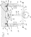
- Fig. 1 shows a schematic partial representation of an exemplary embodiment of a diaphragm pump 10 according to the invention, which can in particular be a diaphragm vacuum pump.
- the membrane pump 10 comprises a scoop chamber 14 which can be acted upon by a membrane 12 and an inlet valve 16 and an outlet valve 18, via which a medium 20 is sucked into the scoop chamber 14 in a suction phase and is expelled from the scoop chamber 14 in a compression phase.
- the inlet valve 16, the outlet valve 18 and the membrane 12 are integrated in a single coherent component 22 in the form of a common membrane.
- the section comprising the inlet valve 16 and the section of the component 22 comprising the outlet valve 18 are each positively controlled via an actuator 24.
- At least the section of the component 22 comprising the membrane 12 can be acted upon by a crank mechanism 26.
- the actuators 24 are coupled to this crank mechanism 26.
- the actuators 24 each comprise a swivel arm 28 which is rotatably supported at one end about a swivel axis 30 and with its other end on a cam 32 (cf. also Fig. 2 ) of the crank mechanism 26, and a plunger 34 extending in the vertical direction, which can be acted upon by the swivel arm 28 and can be pressed in the vertical direction against the section comprising the inlet valve 16 or the section comprising the individual valve 22 comprising the outlet valve 18.
- both the section comprising the inlet valve 16 and the section of the component 22 comprising the outlet valve 18 can each be acted upon by the respective actuator 24 against the force of a compression spring 36. After actuation of the intake valve 16 or exhaust valve 18 by the relevant actuator 24, this valve is reset by the associated compression spring 36.
- the crank mechanism 26 comprises a connecting rod 38 which is arranged between an eccentric shaft 40 and a piston element 42 which acts on the individual connected component 22.
- the common membrane 22 is clamped between a head cover 44 and the housing 46 of the membrane pump 10.
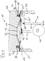
- Fig. 2 shows a schematic side view of the connecting rod 38 ( Fig. 1 ) coupled eccentric shaft 40 and the cams 32 of the crank mechanism 26, which are arranged and designed with respect to the eccentric shaft 40 in such a way that the valves 16, 18 are controlled in accordance with the pumping rhythm controlled by the movement of the connecting rod 38 and thus by the rotating eccentric shaft 40 will.
- Fig. 3 is a top view of the component 22 of the diaphragm pump 10 which comprises the inlet valve 16, the outlet valve 18 and the diaphragm 12. How Fig. 3 shows, the component 22 in the region of the valves 16, 18 each comprises a corresponding sealing surface.
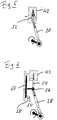
- Fig. 4 shows a schematic partial representation of a further exemplary embodiment of a diaphragm pump 10 according to the invention, which differs from that in FIG the Fig. 1 reproduced embodiment essentially differs in that a respective actuator 24 in the present case comprises a two-armed lever rotatably mounted about an axis 48.
- the lever abuts the eccentric shaft 40 of the crank mechanism 26 with a generally vertically extending portion 24 'and is provided with a generally vertically upwardly extending extension 24 "' at the free end of a generally horizontally extending portion 24".
- the inlet valve 16 or the outlet valve 18 can be acted upon accordingly via the attachment 24 ′ ′′.
- this diaphragm pump 10 has at least essentially the same structure as that of FIG Fig. 1 , corresponding parts being assigned the same reference numerals.
- the connecting rod 38 (cf. Fig. 1 ) of the crank mechanism 26 of a respective diaphragm pump 10 is via a crosshead 50 (cf. Fig. 6 ) coupled to the piston element 42 acting on the component 22.
- Fig. 5 shows a schematic representation of a piston drive without a crosshead.
- the connecting rod 38 is connected directly to the piston element 42 via a piston pin 52.
- FIG. 6 an exemplary embodiment of a piston drive with crosshead 50 is shown in a schematic representation.
- the connecting rod 38 is coupled via a crosshead 50 to the piston element 42 which acts on the individual connected component 22.
- the piston rod 54 is rigidly connected to the bottom of the piston element 42 and a pivot bearing 56 of the crosshead 50.
- the pivot bearing 56 is arranged on a sliding shoe 58 of the crosshead, which is displaceable along a sliding bearing wall 60. In such a crosshead arrangement, the piston element 42 is kept free from transverse forces.
- the actuators 24 can also each comprise an electromagnet, a piezo element or another electrically controllable exciter.
- a respective actuator 24 can be controlled, for example, via a light barrier, a magnetic coil or in some other way without contact, in particular by a crank mechanism.
Landscapes
- Engineering & Computer Science (AREA)
- Mechanical Engineering (AREA)
- General Engineering & Computer Science (AREA)
- Reciprocating Pumps (AREA)
Claims (7)
- Pompe à vide à membrane (10) comportant une chambre d'aspiration (14) susceptible d'être sollicitée via une membrane (12), et une soupape d'entrée (16) ainsi qu'une soupape de sortie (18), par lesquelles un fluide (20) est aspiré dans la chambre d'aspiration (14) pendant une phase d'aspiration et il est éjecté hors de la chambre d'aspiration (14) pendant une phase de compression, la soupape d'entrée (16), la soupape de sortie (18) et la membrane (12) étant intégrées dans un unique composant cohérent (22),
caractérisée en ce qu'une commande de la soupape d'entrée (16) et/ou de la soupape de sortie (18) est dérivée d'un entraînement (26) de la membrane (12), au moins la portion comprenant la membrane (12) de l'unique composant cohérent (22) est susceptible d'être sollicitée par un entraînement à manivelle (26) l'entraînement à manivelle (26) comprend une bielle (38) qui est agencée entre un arbre excentrique (40) et un élément formant piston (42) sollicitant l'unique composant cohérent (22), et la bielle (38) est couplée à l'élément formant piston (42) sollicitant l'unique composant cohérent (22), au moyen d'une tête en croix (50). - Pompe à vide à membrane selon la revendication 1,
caractérisée en ce que
le mouvement de la soupape d'entrée (16) et/ou de la soupape de sortie (18) est commandé à force par l'entraînement (26). - Pompe à vide à membrane selon la revendication 1 ou 2,
caractérisée en ce que
la portion comprenant la soupape d'entrée (16) et/ou la portion comprenant la soupape de sortie (18) de l'unique composant cohérent (22) est commandée à force par un actionneur respectif (24). - Pompe à vide à membrane selon la revendication 1,
caractérisée en ce que
au moins un actionneur (24) est couplé à l'entraînement à manivelle (26) ou à l'entraînement linéaire, ou bien il est inclus dans celui-ci. - Pompe à vide à membrane selon la revendication 3 ou 4,
caractérisée en ce que
au moins un actionneur (24) comprend un excitateur pilotable par voie électrique, en particulier un électroaimant ou un élément piézoélectrique. - Pompe à vide à membrane selon l'une des revendications précédentes,
caractérisée en ce que
la portion comprenant la soupape d'entrée (16) et/ou la portion comprenant la soupape de sortie (18) de l'unique composant cohérent (22) est susceptible d'être sollicitée par l'actionneur respectif (24) à l'encontre d'une force élastique. - Pompe à vide à membrane selon l'une des revendications 3 à 6,
caractérisée en ce que
un actionneur respectif (24) est pilotable sans contact physique, en particulier par une barrière lumineuse ou par une bobine magnétique.
Applications Claiming Priority (1)
| Application Number | Priority Date | Filing Date | Title |
|---|---|---|---|
| DE102014103459.7A DE102014103459A1 (de) | 2014-03-13 | 2014-03-13 | Membranpumpe |
Publications (3)
| Publication Number | Publication Date |
|---|---|
| EP2918835A1 EP2918835A1 (fr) | 2015-09-16 |
| EP2918835B1 EP2918835B1 (fr) | 2017-03-29 |
| EP2918835B2 true EP2918835B2 (fr) | 2020-04-29 |
Family
ID=52358666
Family Applications (1)
| Application Number | Title | Priority Date | Filing Date |
|---|---|---|---|
| EP15151943.6A Active EP2918835B2 (fr) | 2014-03-13 | 2015-01-21 | Pompe à membrane |
Country Status (2)
| Country | Link |
|---|---|
| EP (1) | EP2918835B2 (fr) |
| DE (1) | DE102014103459A1 (fr) |
Families Citing this family (2)
| Publication number | Priority date | Publication date | Assignee | Title |
|---|---|---|---|---|
| CN112811519B (zh) * | 2021-01-06 | 2022-07-01 | 杭州电子科技大学 | 一种净水器水处理增压泵能量回收系统 |
| DE102021204407A1 (de) | 2021-05-03 | 2022-11-03 | Robert Bosch Gesellschaft mit beschränkter Haftung | Verfahren zum Betreiben einer Pumpe und Fluid-Versorgungssystem |
Family Cites Families (7)
| Publication number | Priority date | Publication date | Assignee | Title |
|---|---|---|---|---|
| DE809457C (de) * | 1947-03-12 | 1951-07-30 | Marcel Rene Armand Chabay | Kolbenverdichter |
| US2785638A (en) * | 1954-04-08 | 1957-03-19 | Clifford B Moller | Force pump for slurries |
| US4411603A (en) * | 1981-06-24 | 1983-10-25 | Cordis Dow Corp. | Diaphragm type blood pump for medical use |
| DE29723455U1 (de) | 1997-12-10 | 1998-09-17 | ASF THOMAS Industries GmbH, 82178 Puchheim | Membrane für Membranpumpe |
| IL154779A0 (en) * | 2000-09-14 | 2003-10-31 | Jan W Beenker | Method and device for conveying media |
| DE202010002145U1 (de) * | 2010-02-09 | 2011-09-07 | Vacuubrand Gmbh + Co Kg | Membranvakuumpumpe |
| DE102010019057A1 (de) * | 2010-05-03 | 2011-11-03 | Wmf Württembergische Metallwarenfabrik Ag | Fluidpumpe |
-
2014
- 2014-03-13 DE DE102014103459.7A patent/DE102014103459A1/de not_active Withdrawn
-
2015
- 2015-01-21 EP EP15151943.6A patent/EP2918835B2/fr active Active
Also Published As
| Publication number | Publication date |
|---|---|
| DE102014103459A1 (de) | 2015-09-17 |
| EP2918835B1 (fr) | 2017-03-29 |
| EP2918835A1 (fr) | 2015-09-16 |
Similar Documents
| Publication | Publication Date | Title |
|---|---|---|
| EP2550454A1 (fr) | Procédé de commande et/ou de réglage d'une pompe de dosage | |
| WO1994029595A1 (fr) | Regulateur a plusieurs etages pour pompes a lubrifiant a debit continuellement variable | |
| EP3077674B1 (fr) | Système hydraulique | |
| WO2006037671A1 (fr) | Pompe a piston radial | |
| DE4200305A1 (de) | Regelbare fluegelzellenpumpe in kompakter bauweise | |
| EP3098457B1 (fr) | Actionneur linéaire hydrostatique et dispositif avec actionneurs linéaires hydrostatiques | |
| EP2725226A1 (fr) | Pompe à pistons | |
| WO2010055100A1 (fr) | Unité pompe pour une pompe à haute pression | |
| EP2889481B2 (fr) | Procédé d'étalonnage d'une pompe sous vide à membrane et pompe sous vide à membrane | |
| EP2918835B2 (fr) | Pompe à membrane | |
| DE102008062483A1 (de) | Axialkolbenmaschine mit Pulsationsminderung | |
| EP3482076B1 (fr) | Couvercle de tête de cylindre pour un compresseur de réfrigérant | |
| DE102007060174A1 (de) | Vakuumpumpe sowie Verfahren zum Betreiben einer Vakuumpumpe | |
| EP2354546B1 (fr) | Pompe sous vide à membrane | |
| EP2655895B1 (fr) | Entraînement hydraulique | |
| EP2795095B1 (fr) | Pompe, en particulier une pompe á carburant pour un systeme d'injection de carburant | |
| EP4004370B1 (fr) | Dispositif de soupape pour un compresseur à piston | |
| EP3119596B1 (fr) | Dispositif permettant d'étanchéifier et de gonfler des gonflables | |
| EP1831547B1 (fr) | Pompe a piston comportant au moins un element piston differentiel | |
| EP3714162A1 (fr) | Procédé pour faire fonctionner un compresseur à piston et compresseur à piston | |
| DE102013105072A1 (de) | Membranpumpe mit Lagensteuerung | |
| DD211388A5 (de) | Wassergetriebene kraftmaschine | |
| AT504981A2 (de) | Ventilantrieb | |
| DE102012024704A1 (de) | Rollkolbenverdichter mit veränderbarer Förderleistung | |
| AT507614A1 (de) | Stirlingmaschine |
Legal Events
| Date | Code | Title | Description |
|---|---|---|---|
| PUAI | Public reference made under article 153(3) epc to a published international application that has entered the european phase |
Free format text: ORIGINAL CODE: 0009012 |
|
| AK | Designated contracting states |
Kind code of ref document: A1 Designated state(s): AL AT BE BG CH CY CZ DE DK EE ES FI FR GB GR HR HU IE IS IT LI LT LU LV MC MK MT NL NO PL PT RO RS SE SI SK SM TR |
|
| AX | Request for extension of the european patent |
Extension state: BA ME |
|
| 17P | Request for examination filed |
Effective date: 20160316 |
|
| RBV | Designated contracting states (corrected) |
Designated state(s): AL AT BE BG CH CY CZ DE DK EE ES FI FR GB GR HR HU IE IS IT LI LT LU LV MC MK MT NL NO PL PT RO RS SE SI SK SM TR |
|
| RIC1 | Information provided on ipc code assigned before grant |
Ipc: F04B 39/08 20060101AFI20160830BHEP Ipc: F04B 43/00 20060101ALI20160830BHEP Ipc: F04B 45/04 20060101ALI20160830BHEP Ipc: F04B 43/02 20060101ALI20160830BHEP |
|
| GRAP | Despatch of communication of intention to grant a patent |
Free format text: ORIGINAL CODE: EPIDOSNIGR1 |
|
| INTG | Intention to grant announced |
Effective date: 20161014 |
|
| GRAS | Grant fee paid |
Free format text: ORIGINAL CODE: EPIDOSNIGR3 |
|
| STAA | Information on the status of an ep patent application or granted ep patent |
Free format text: STATUS: GRANT OF PATENT IS INTENDED |
|
| GRAA | (expected) grant |
Free format text: ORIGINAL CODE: 0009210 |
|
| STAA | Information on the status of an ep patent application or granted ep patent |
Free format text: STATUS: THE PATENT HAS BEEN GRANTED |
|
| AK | Designated contracting states |
Kind code of ref document: B1 Designated state(s): AL AT BE BG CH CY CZ DE DK EE ES FI FR GB GR HR HU IE IS IT LI LT LU LV MC MK MT NL NO PL PT RO RS SE SI SK SM TR |
|
| REG | Reference to a national code |
Ref country code: GB Ref legal event code: FG4D Free format text: NOT ENGLISH |
|
| REG | Reference to a national code |
Ref country code: CH Ref legal event code: EP |
|
| REG | Reference to a national code |
Ref country code: AT Ref legal event code: REF Ref document number: 880042 Country of ref document: AT Kind code of ref document: T Effective date: 20170415 |
|
| REG | Reference to a national code |
Ref country code: IE Ref legal event code: FG4D Free format text: LANGUAGE OF EP DOCUMENT: GERMAN |
|
| REG | Reference to a national code |
Ref country code: DE Ref legal event code: R096 Ref document number: 502015000762 Country of ref document: DE |
|
| PG25 | Lapsed in a contracting state [announced via postgrant information from national office to epo] |
Ref country code: LT Free format text: LAPSE BECAUSE OF FAILURE TO SUBMIT A TRANSLATION OF THE DESCRIPTION OR TO PAY THE FEE WITHIN THE PRESCRIBED TIME-LIMIT Effective date: 20170329 Ref country code: GR Free format text: LAPSE BECAUSE OF FAILURE TO SUBMIT A TRANSLATION OF THE DESCRIPTION OR TO PAY THE FEE WITHIN THE PRESCRIBED TIME-LIMIT Effective date: 20170630 Ref country code: HR Free format text: LAPSE BECAUSE OF FAILURE TO SUBMIT A TRANSLATION OF THE DESCRIPTION OR TO PAY THE FEE WITHIN THE PRESCRIBED TIME-LIMIT Effective date: 20170329 Ref country code: FI Free format text: LAPSE BECAUSE OF FAILURE TO SUBMIT A TRANSLATION OF THE DESCRIPTION OR TO PAY THE FEE WITHIN THE PRESCRIBED TIME-LIMIT Effective date: 20170329 Ref country code: NO Free format text: LAPSE BECAUSE OF FAILURE TO SUBMIT A TRANSLATION OF THE DESCRIPTION OR TO PAY THE FEE WITHIN THE PRESCRIBED TIME-LIMIT Effective date: 20170629 |
|
| REG | Reference to a national code |
Ref country code: NL Ref legal event code: MP Effective date: 20170329 |
|
| PG25 | Lapsed in a contracting state [announced via postgrant information from national office to epo] |
Ref country code: BG Free format text: LAPSE BECAUSE OF FAILURE TO SUBMIT A TRANSLATION OF THE DESCRIPTION OR TO PAY THE FEE WITHIN THE PRESCRIBED TIME-LIMIT Effective date: 20170629 Ref country code: RS Free format text: LAPSE BECAUSE OF FAILURE TO SUBMIT A TRANSLATION OF THE DESCRIPTION OR TO PAY THE FEE WITHIN THE PRESCRIBED TIME-LIMIT Effective date: 20170329 Ref country code: LV Free format text: LAPSE BECAUSE OF FAILURE TO SUBMIT A TRANSLATION OF THE DESCRIPTION OR TO PAY THE FEE WITHIN THE PRESCRIBED TIME-LIMIT Effective date: 20170329 Ref country code: SE Free format text: LAPSE BECAUSE OF FAILURE TO SUBMIT A TRANSLATION OF THE DESCRIPTION OR TO PAY THE FEE WITHIN THE PRESCRIBED TIME-LIMIT Effective date: 20170329 |
|
| PG25 | Lapsed in a contracting state [announced via postgrant information from national office to epo] |
Ref country code: NL Free format text: LAPSE BECAUSE OF FAILURE TO SUBMIT A TRANSLATION OF THE DESCRIPTION OR TO PAY THE FEE WITHIN THE PRESCRIBED TIME-LIMIT Effective date: 20170329 |
|
| PG25 | Lapsed in a contracting state [announced via postgrant information from national office to epo] |
Ref country code: EE Free format text: LAPSE BECAUSE OF FAILURE TO SUBMIT A TRANSLATION OF THE DESCRIPTION OR TO PAY THE FEE WITHIN THE PRESCRIBED TIME-LIMIT Effective date: 20170329 Ref country code: CZ Free format text: LAPSE BECAUSE OF FAILURE TO SUBMIT A TRANSLATION OF THE DESCRIPTION OR TO PAY THE FEE WITHIN THE PRESCRIBED TIME-LIMIT Effective date: 20170329 Ref country code: RO Free format text: LAPSE BECAUSE OF FAILURE TO SUBMIT A TRANSLATION OF THE DESCRIPTION OR TO PAY THE FEE WITHIN THE PRESCRIBED TIME-LIMIT Effective date: 20170329 Ref country code: ES Free format text: LAPSE BECAUSE OF FAILURE TO SUBMIT A TRANSLATION OF THE DESCRIPTION OR TO PAY THE FEE WITHIN THE PRESCRIBED TIME-LIMIT Effective date: 20170329 Ref country code: SK Free format text: LAPSE BECAUSE OF FAILURE TO SUBMIT A TRANSLATION OF THE DESCRIPTION OR TO PAY THE FEE WITHIN THE PRESCRIBED TIME-LIMIT Effective date: 20170329 |
|
| PG25 | Lapsed in a contracting state [announced via postgrant information from national office to epo] |
Ref country code: IS Free format text: LAPSE BECAUSE OF FAILURE TO SUBMIT A TRANSLATION OF THE DESCRIPTION OR TO PAY THE FEE WITHIN THE PRESCRIBED TIME-LIMIT Effective date: 20170729 Ref country code: PL Free format text: LAPSE BECAUSE OF FAILURE TO SUBMIT A TRANSLATION OF THE DESCRIPTION OR TO PAY THE FEE WITHIN THE PRESCRIBED TIME-LIMIT Effective date: 20170329 Ref country code: SM Free format text: LAPSE BECAUSE OF FAILURE TO SUBMIT A TRANSLATION OF THE DESCRIPTION OR TO PAY THE FEE WITHIN THE PRESCRIBED TIME-LIMIT Effective date: 20170329 |
|
| REG | Reference to a national code |
Ref country code: DE Ref legal event code: R026 Ref document number: 502015000762 Country of ref document: DE |
|
| PLBI | Opposition filed |
Free format text: ORIGINAL CODE: 0009260 |
|
| PLAX | Notice of opposition and request to file observation + time limit sent |
Free format text: ORIGINAL CODE: EPIDOSNOBS2 |
|
| PG25 | Lapsed in a contracting state [announced via postgrant information from national office to epo] |
Ref country code: DK Free format text: LAPSE BECAUSE OF FAILURE TO SUBMIT A TRANSLATION OF THE DESCRIPTION OR TO PAY THE FEE WITHIN THE PRESCRIBED TIME-LIMIT Effective date: 20170329 |
|
| 26 | Opposition filed |
Opponent name: KNF NEUBERGER GMBH Effective date: 20171221 |
|
| PLBB | Reply of patent proprietor to notice(s) of opposition received |
Free format text: ORIGINAL CODE: EPIDOSNOBS3 |
|
| PG25 | Lapsed in a contracting state [announced via postgrant information from national office to epo] |
Ref country code: SI Free format text: LAPSE BECAUSE OF FAILURE TO SUBMIT A TRANSLATION OF THE DESCRIPTION OR TO PAY THE FEE WITHIN THE PRESCRIBED TIME-LIMIT Effective date: 20170329 |
|
| REG | Reference to a national code |
Ref country code: CH Ref legal event code: PL |
|
| PG25 | Lapsed in a contracting state [announced via postgrant information from national office to epo] |
Ref country code: MT Free format text: LAPSE BECAUSE OF FAILURE TO SUBMIT A TRANSLATION OF THE DESCRIPTION OR TO PAY THE FEE WITHIN THE PRESCRIBED TIME-LIMIT Effective date: 20170329 |
|
| PG25 | Lapsed in a contracting state [announced via postgrant information from national office to epo] |
Ref country code: LU Free format text: LAPSE BECAUSE OF NON-PAYMENT OF DUE FEES Effective date: 20180121 Ref country code: FR Free format text: LAPSE BECAUSE OF NON-PAYMENT OF DUE FEES Effective date: 20180131 |
|
| REG | Reference to a national code |
Ref country code: IE Ref legal event code: MM4A |
|
| REG | Reference to a national code |
Ref country code: FR Ref legal event code: ST Effective date: 20180928 |
|
| REG | Reference to a national code |
Ref country code: BE Ref legal event code: MM Effective date: 20180131 |
|
| PG25 | Lapsed in a contracting state [announced via postgrant information from national office to epo] |
Ref country code: CH Free format text: LAPSE BECAUSE OF NON-PAYMENT OF DUE FEES Effective date: 20180131 Ref country code: BE Free format text: LAPSE BECAUSE OF NON-PAYMENT OF DUE FEES Effective date: 20180131 Ref country code: LI Free format text: LAPSE BECAUSE OF NON-PAYMENT OF DUE FEES Effective date: 20180131 |
|
| PG25 | Lapsed in a contracting state [announced via postgrant information from national office to epo] |
Ref country code: IE Free format text: LAPSE BECAUSE OF NON-PAYMENT OF DUE FEES Effective date: 20180121 |
|
| PG25 | Lapsed in a contracting state [announced via postgrant information from national office to epo] |
Ref country code: MC Free format text: LAPSE BECAUSE OF FAILURE TO SUBMIT A TRANSLATION OF THE DESCRIPTION OR TO PAY THE FEE WITHIN THE PRESCRIBED TIME-LIMIT Effective date: 20170329 |
|
| PUAH | Patent maintained in amended form |
Free format text: ORIGINAL CODE: 0009272 |
|
| STAA | Information on the status of an ep patent application or granted ep patent |
Free format text: STATUS: PATENT MAINTAINED AS AMENDED |
|
| PG25 | Lapsed in a contracting state [announced via postgrant information from national office to epo] |
Ref country code: TR Free format text: LAPSE BECAUSE OF FAILURE TO SUBMIT A TRANSLATION OF THE DESCRIPTION OR TO PAY THE FEE WITHIN THE PRESCRIBED TIME-LIMIT Effective date: 20170329 |
|
| 27A | Patent maintained in amended form |
Effective date: 20200429 |
|
| AK | Designated contracting states |
Kind code of ref document: B2 Designated state(s): AL AT BE BG CH CY CZ DE DK EE ES FI FR GB GR HR HU IE IS IT LI LT LU LV MC MK MT NL NO PL PT RO RS SE SI SK SM TR |
|
| REG | Reference to a national code |
Ref country code: DE Ref legal event code: R102 Ref document number: 502015000762 Country of ref document: DE |
|
| PG25 | Lapsed in a contracting state [announced via postgrant information from national office to epo] |
Ref country code: PT Free format text: LAPSE BECAUSE OF FAILURE TO SUBMIT A TRANSLATION OF THE DESCRIPTION OR TO PAY THE FEE WITHIN THE PRESCRIBED TIME-LIMIT Effective date: 20170329 |
|
| PG25 | Lapsed in a contracting state [announced via postgrant information from national office to epo] |
Ref country code: MK Free format text: LAPSE BECAUSE OF NON-PAYMENT OF DUE FEES Effective date: 20170329 Ref country code: CY Free format text: LAPSE BECAUSE OF FAILURE TO SUBMIT A TRANSLATION OF THE DESCRIPTION OR TO PAY THE FEE WITHIN THE PRESCRIBED TIME-LIMIT Effective date: 20170329 Ref country code: HU Free format text: LAPSE BECAUSE OF FAILURE TO SUBMIT A TRANSLATION OF THE DESCRIPTION OR TO PAY THE FEE WITHIN THE PRESCRIBED TIME-LIMIT; INVALID AB INITIO Effective date: 20150121 |
|
| PG25 | Lapsed in a contracting state [announced via postgrant information from national office to epo] |
Ref country code: AL Free format text: LAPSE BECAUSE OF FAILURE TO SUBMIT A TRANSLATION OF THE DESCRIPTION OR TO PAY THE FEE WITHIN THE PRESCRIBED TIME-LIMIT Effective date: 20170329 |
|
| REG | Reference to a national code |
Ref country code: AT Ref legal event code: MM01 Ref document number: 880042 Country of ref document: AT Kind code of ref document: T Effective date: 20200121 |
|
| PG25 | Lapsed in a contracting state [announced via postgrant information from national office to epo] |
Ref country code: AT Free format text: LAPSE BECAUSE OF NON-PAYMENT OF DUE FEES Effective date: 20200121 |
|
| PGFP | Annual fee paid to national office [announced via postgrant information from national office to epo] |
Ref country code: DE Payment date: 20240326 Year of fee payment: 10 Ref country code: GB Payment date: 20240123 Year of fee payment: 10 |
|
| PGFP | Annual fee paid to national office [announced via postgrant information from national office to epo] |
Ref country code: IT Payment date: 20240129 Year of fee payment: 10 |