EP2918478A1 - Vehicle control device - Google Patents
Vehicle control device Download PDFInfo
- Publication number
- EP2918478A1 EP2918478A1 EP13852678.5A EP13852678A EP2918478A1 EP 2918478 A1 EP2918478 A1 EP 2918478A1 EP 13852678 A EP13852678 A EP 13852678A EP 2918478 A1 EP2918478 A1 EP 2918478A1
- Authority
- EP
- European Patent Office
- Prior art keywords
- engine
- steering
- voltage
- battery
- power
- Prior art date
- Legal status (The legal status is an assumption and is not a legal conclusion. Google has not performed a legal analysis and makes no representation as to the accuracy of the status listed.)
- Granted
Links
Images







Classifications
-
- B—PERFORMING OPERATIONS; TRANSPORTING
- B62—LAND VEHICLES FOR TRAVELLING OTHERWISE THAN ON RAILS
- B62D—MOTOR VEHICLES; TRAILERS
- B62D5/00—Power-assisted or power-driven steering
- B62D5/04—Power-assisted or power-driven steering electrical, e.g. using an electric servo-motor connected to, or forming part of, the steering gear
- B62D5/0457—Power-assisted or power-driven steering electrical, e.g. using an electric servo-motor connected to, or forming part of, the steering gear characterised by control features of the drive means as such
- B62D5/0481—Power-assisted or power-driven steering electrical, e.g. using an electric servo-motor connected to, or forming part of, the steering gear characterised by control features of the drive means as such monitoring the steering system, e.g. failures
-
- B—PERFORMING OPERATIONS; TRANSPORTING
- B62—LAND VEHICLES FOR TRAVELLING OTHERWISE THAN ON RAILS
- B62D—MOTOR VEHICLES; TRAILERS
- B62D5/00—Power-assisted or power-driven steering
- B62D5/04—Power-assisted or power-driven steering electrical, e.g. using an electric servo-motor connected to, or forming part of, the steering gear
- B62D5/0457—Power-assisted or power-driven steering electrical, e.g. using an electric servo-motor connected to, or forming part of, the steering gear characterised by control features of the drive means as such
- B62D5/046—Controlling the motor
-
- F—MECHANICAL ENGINEERING; LIGHTING; HEATING; WEAPONS; BLASTING
- F02—COMBUSTION ENGINES; HOT-GAS OR COMBUSTION-PRODUCT ENGINE PLANTS
- F02D—CONTROLLING COMBUSTION ENGINES
- F02D29/00—Controlling engines, such controlling being peculiar to the devices driven thereby, the devices being other than parts or accessories essential to engine operation, e.g. controlling of engines by signals external thereto
- F02D29/02—Controlling engines, such controlling being peculiar to the devices driven thereby, the devices being other than parts or accessories essential to engine operation, e.g. controlling of engines by signals external thereto peculiar to engines driving vehicles; peculiar to engines driving variable pitch propellers
-
- F—MECHANICAL ENGINEERING; LIGHTING; HEATING; WEAPONS; BLASTING
- F02—COMBUSTION ENGINES; HOT-GAS OR COMBUSTION-PRODUCT ENGINE PLANTS
- F02N—STARTING OF COMBUSTION ENGINES; STARTING AIDS FOR SUCH ENGINES, NOT OTHERWISE PROVIDED FOR
- F02N11/00—Starting of engines by means of electric motors
- F02N11/04—Starting of engines by means of electric motors the motors being associated with current generators
-
- F—MECHANICAL ENGINEERING; LIGHTING; HEATING; WEAPONS; BLASTING
- F02—COMBUSTION ENGINES; HOT-GAS OR COMBUSTION-PRODUCT ENGINE PLANTS
- F02N—STARTING OF COMBUSTION ENGINES; STARTING AIDS FOR SUCH ENGINES, NOT OTHERWISE PROVIDED FOR
- F02N11/00—Starting of engines by means of electric motors
- F02N11/08—Circuits specially adapted for starting of engines
- F02N11/0814—Circuits specially adapted for starting of engines comprising means for controlling automatic idle-start-stop
- F02N11/0818—Conditions for starting or stopping the engine or for deactivating the idle-start-stop mode
-
- F—MECHANICAL ENGINEERING; LIGHTING; HEATING; WEAPONS; BLASTING
- F02—COMBUSTION ENGINES; HOT-GAS OR COMBUSTION-PRODUCT ENGINE PLANTS
- F02N—STARTING OF COMBUSTION ENGINES; STARTING AIDS FOR SUCH ENGINES, NOT OTHERWISE PROVIDED FOR
- F02N11/00—Starting of engines by means of electric motors
- F02N11/08—Circuits specially adapted for starting of engines
- F02N11/087—Details of the switching means in starting circuits, e.g. relays or electronic switches
-
- F—MECHANICAL ENGINEERING; LIGHTING; HEATING; WEAPONS; BLASTING
- F02—COMBUSTION ENGINES; HOT-GAS OR COMBUSTION-PRODUCT ENGINE PLANTS
- F02N—STARTING OF COMBUSTION ENGINES; STARTING AIDS FOR SUCH ENGINES, NOT OTHERWISE PROVIDED FOR
- F02N2200/00—Parameters used for control of starting apparatus
- F02N2200/02—Parameters used for control of starting apparatus said parameters being related to the engine
- F02N2200/024—Engine oil temperature
-
- F—MECHANICAL ENGINEERING; LIGHTING; HEATING; WEAPONS; BLASTING
- F02—COMBUSTION ENGINES; HOT-GAS OR COMBUSTION-PRODUCT ENGINE PLANTS
- F02N—STARTING OF COMBUSTION ENGINES; STARTING AIDS FOR SUCH ENGINES, NOT OTHERWISE PROVIDED FOR
- F02N2200/00—Parameters used for control of starting apparatus
- F02N2200/06—Parameters used for control of starting apparatus said parameters being related to the power supply or driving circuits for the starter
- F02N2200/063—Battery voltage
-
- F—MECHANICAL ENGINEERING; LIGHTING; HEATING; WEAPONS; BLASTING
- F02—COMBUSTION ENGINES; HOT-GAS OR COMBUSTION-PRODUCT ENGINE PLANTS
- F02N—STARTING OF COMBUSTION ENGINES; STARTING AIDS FOR SUCH ENGINES, NOT OTHERWISE PROVIDED FOR
- F02N2200/00—Parameters used for control of starting apparatus
- F02N2200/10—Parameters used for control of starting apparatus said parameters being related to driver demands or status
- F02N2200/101—Accelerator pedal position
-
- F—MECHANICAL ENGINEERING; LIGHTING; HEATING; WEAPONS; BLASTING
- F02—COMBUSTION ENGINES; HOT-GAS OR COMBUSTION-PRODUCT ENGINE PLANTS
- F02N—STARTING OF COMBUSTION ENGINES; STARTING AIDS FOR SUCH ENGINES, NOT OTHERWISE PROVIDED FOR
- F02N2200/00—Parameters used for control of starting apparatus
- F02N2200/10—Parameters used for control of starting apparatus said parameters being related to driver demands or status
- F02N2200/102—Brake pedal position
-
- F—MECHANICAL ENGINEERING; LIGHTING; HEATING; WEAPONS; BLASTING
- F02—COMBUSTION ENGINES; HOT-GAS OR COMBUSTION-PRODUCT ENGINE PLANTS
- F02N—STARTING OF COMBUSTION ENGINES; STARTING AIDS FOR SUCH ENGINES, NOT OTHERWISE PROVIDED FOR
- F02N2250/00—Problems related to engine starting or engine's starting apparatus
- F02N2250/02—Battery voltage drop at start, e.g. drops causing ECU reset
-
- Y—GENERAL TAGGING OF NEW TECHNOLOGICAL DEVELOPMENTS; GENERAL TAGGING OF CROSS-SECTIONAL TECHNOLOGIES SPANNING OVER SEVERAL SECTIONS OF THE IPC; TECHNICAL SUBJECTS COVERED BY FORMER USPC CROSS-REFERENCE ART COLLECTIONS [XRACs] AND DIGESTS
- Y02—TECHNOLOGIES OR APPLICATIONS FOR MITIGATION OR ADAPTATION AGAINST CLIMATE CHANGE
- Y02T—CLIMATE CHANGE MITIGATION TECHNOLOGIES RELATED TO TRANSPORTATION
- Y02T10/00—Road transport of goods or passengers
- Y02T10/10—Internal combustion engine [ICE] based vehicles
- Y02T10/40—Engine management systems
Definitions
- the present invention relates to a vehicle control device.
- Patent Document 1 listed below discloses a device in which power stops being supplied to an power steering motor in the event of a transition to an idling stop.
- Patent Document 1 Japanese Laid-Open Patent Application No. 2010-248964
- Patent Document 1 discloses no matter concerning the timing at which power start to be supplied once more to an power steering motor when an engine is restarted after an idling stop. After the engine has restarted, it has not always been possible to impart assist torque to the steering torque of the driver when the vehicle begins to move.
- the present invention focuses on the above problem, it being an object of the invention to provide a vehicle control device that can quickly impart assist torque to the steering torque of the driver by means of a power-steering mechanism after the engine has restarted.
- a power-steering mechanism when an engine is to be restarted, a power-steering mechanism is reactivated when voltage fluctuation of a battery is equal to or less than a predetermined fluctuation range after startup of the engine has been initiated.
- the power-steering mechanism is reactivated while voltage fluctuation of the battery is stable, and assist torque can therefore be quickly and stably outputted after idling stop control has been canceled.
- FIG. 1 is a schematic diagram of a vehicle system equipped with power steering and idling stop.
- This vehicle system has, as a steering mechanism, a steering wheel 1, a steering shaft 2 connected to the steering wheel 1, a pinion 3 that rotates integrally with the steering shaft 2, a rack 4 for converting the rotational motion of the pinion 3 into linear motion in the vehicle width direction, tie rods 5 connected to both ends of the rack 4, and steered wheels 6 that are connected to the tie rods 5 and that perform steering in accordance with the steered amount of the steering wheel 1.
- the vehicle system also has, as a power-steering mechanism, an assist motor 7 for outputting assist torque that supplements the steering torque of the driver, and a pinion 8 that rotates integrally with a motor shaft of the assist motor 7 and meshes with the rack 4.
- the vehicle system also has an engine 9 as a drive source, and the drive force of the engine 9 is outputted to an automatic transmission 10.
- the engine 9 is provided with a starter motor 11 for cranking the engine 9 when the engine starts up.
- a compressor 13 connected via a belt with a crankshaft of the engine 9. The compressor 13, which is operated by the engine 9, compresses a catalyst of a cooler 12 for sending cold air into a passenger compartment.
- a side mounted starter generator (SSG) 14 connected via a belt with the crankshaft of the engine 9. The SSG 14 cranks the engine 9 when the engine starts up, and the SSG is operated by the engine 9 to generate power after the engine has started up.
- SSG side mounted starter generator
- the SSG 14 stores the power generated after the engine has started up in the battery 15.
- the engine 9 is connected to a heater 16 for sending hot air into the passenger compartment, and the heater 16 utilizes the heat of the engine 9.
- the configuration of the control system includes an idling stop control unit 17, an automatic transmission control unit 18, and a power steering control unit 19. These along with other electronic control units 20, 21, 22 share information through a controller area network (CAN) 23.
- CAN controller area network
- a brake switch 24 for outputting information on whether or not a brake pedal is being operated
- a PN switch 25 for outputting information on whether or not the shift position is P (park) or N (neutral)
- an accelerator position sensor 26 for outputting information on an accelerator pedal position.
- An inhibitor switch 27 showing the shift position is connected to the automatic transmission control unit 18.
- a steering angle sensor 28 for detecting the steering angle of the steering wheel 1, and a steering torque sensor 29 for detecting the steering torque inputted to the steering wheel 1.
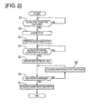
- FIG. 2 is a flowchart showing the flow of control performed in the idling stop control unit 17 and the power steering control unit 19.
- step S1 a determination is made as to whether or not a condition is fulfilled for stopping the engine and entering idling stop control.
- the process advances to step S2, and when the condition is not fulfilled, the determination of step S1 is repeated until the condition is fulfilled.
- the idling stop condition includes conditions such as the vehicle speed being zero, the accelerator pedal position being zero, the brake pedal being pressed, the engine oil or transmission oil being at least a predetermined temperature, and the battery voltage being at least a predetermined voltage, and when these conditions are all fulfilled, the idling stop condition is fulfilled.
- Other conditions may be added to the idling stop condition, which is not particularly limited.
- step S2 the supply of fuel to the engine is stopped, and the process advances to step S3.
- engine stop or “the engine stops” hereinafter refers to a state in which the supply of fuel to the engine has stopped, and, as shall be apparent, includes states in which the engine is not turning, but also includes states in which the supply of fuel has stopped and the engine is turning by inertia.
- step S3 the assist motor 7 stops generating assist torque (steering assistance stops), and the process advances to step S4.
- step S4 a determination is made as to whether or not an idling stop cancel condition is fulfilled.
- the idling stop cancel condition includes conditions such as the accelerator pedal position being greater than zero, the pressing of the brake pedal having been lessened, the engine oil or the transmission oil being less than a predetermined temperature, and the battery voltage being less than a predetermined voltage, and when any of these conditions is fulfilled, the idling stop cancel condition is fulfilled.
- Other conditions may be added to the idling stop cancel condition, which is not particularly limited.
- step S5 the engine 9 is cranked by the SSG 14, and the process advances to step S6.
- step S6 a determination is made as to whether or not the operation of the SSG 14 has ended.
- the process advances to step S7, and when the operation has not ended, the process advances to step S8.
- the SSG 14 ends operation when it is determined that the engine 9 has reached complete combustion.
- the determination that the engine 9 has reached complete combustion is made when the engine speed is equal to or greater than a speed that enables self-sustaining rotation (complete combustion determination speed: 500 [rpm], for example).
- complete combustion determination speed 500 [rpm], for example.
- step S7 the assist motor 7 begins again to generate assist torque (steering assistance is restarted), and the process is ended.
- step S8 the assist motor 7 continues to not generate assist torque (the stopping of steering assistance is continued), and the process advances to step S6.
- step S1 When the idling stop condition is fulfilled, the process advances from step S1 to step S2 and step S3, the supply of fuel to the engine is stopped, and steering assistance is stopped.
- step S4 After the engine stop (idling stop), when the idling stop cancel condition is fulfilled, the process advances from step S4 to step S5, the SSG 14 is operated, and the engine 9 is cranked.
- step S6 When the SSG 14 is operating even after the idling stop cancel condition has been fulfilled, the process advances from step S6 to step S8, and steering assistance remains stopped.
- step S6 When the idling stop cancel condition has been fulfilled and operation of the SSG 14 is ended, the process advances from step S6 to step S7 and steering assistance is restarted.
- FIG. 3 is a time chart showing the change in battery voltage before and after the battery is restarted.
- a power steering normal operating voltage a voltage at which the assist motor 7 can stably generate sufficient assist torque.
- FIG. 4 is a time chart from engine startup through an idling stop until an engine restart.
- FIG. 4(a) shows the engine speed
- FIG. 4(b) shows the operating state of the engine 9
- FIG. 4(c) shows the state of idling stop control
- FIG. 4(d) shows the operating state of the SSG 14
- FIG. 4(e) shows the state of steering assistance
- FIG. 4(f) shows the battery voltage.
- the ignition switch is operated and the engine 9 is cranked.
- the engine 9 is operated by the starter motor 11 at this time.
- Embodiment 1 The effects of Embodiment 1 are described.
- the engine 9 is cranked by the SSG 14 when the engine is restarted after idling stop control is canceled.
- the engine 9 is cranked by the starter motor 11 even when the engine is restarted after idling stop control is canceled.
- a starter bypass relay 31 is provided between the battery 15 and the starter motor 11.
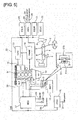
- FIG. 5 is a schematic diagram of a vehicle system equipped with power steering and idling stop.
- This vehicle system has, as a steering mechanism, a steering wheel 1, a steering shaft 2 connected to the steering wheel 1, a pinion 3 that rotates integrally with the steering shaft 2, a rack 4 for converting the rotational motion of the pinion 3 into linear motion in the vehicle width direction, tie rods 5 connected to both ends of the rack 4, and steered wheels 6 that are connected to the tie rods 5 and that perform steering in accordance with the steered amount of the steering wheel 1.
- the vehicle system also has, as a power-steering mechanism, an assist motor 7 for outputting assist torque that supplements the steering torque of the driver, and a pinion 8 that rotates integrally with a motor shaft of the assist motor 7 and meshes with the rack 4.
- the vehicle system also has an engine 9 as a drive source, and the drive force of the engine 9 is outputted to an automatic transmission 10.
- the engine 9 is provided with a starter motor 11 for cranking the engine 9 when the engine starts up.
- a compressor 13 connected via a belt with a crankshaft of the engine 9.
- an alternator 30 connected via a belt with the crankshaft of the engine 9. After engine startup, the alternator 30 is operated by the engine 9 to generate power.
- the starter bypass relay 31 is provided between the starter motor 11 and the battery 15.
- the starter bypass relay 31 is configured from a relay circuit 31a and a resistor circuit 31b provided in parallel to the relay circuit 31a. Normally, the starter bypass relay 31 is off and the relay circuit 31a is closed. At this time, electric current flows through the relay circuit 31a and does not flow to the resistor circuit 31b.
- the starter bypass relay 31 is turned on and the relay circuit 31a is opened. At this time, electric current does not flow to the relay circuit 31 b and does flow through the resistor circuit 31b.
- the engine 9 is connected to a heater 16 for sending hot air into the passenger compartment, and the heater 16 utilizes the heat of the engine 9.
- the configuration of the control system includes an idling stop control unit 17, an automatic transmission control unit 18, and a power steering control unit 19. These along with other electronic control units 20, 21, 22 share information through a controller area network (CAN) 23.
- CAN controller area network
- a brake switch 24 for outputting information on whether or not a brake pedal is being operated
- a PN switch 25 for outputting information on whether or not the shift position is P (park) or N (neutral)
- an accelerator position sensor 26 for outputting information on an accelerator pedal position.
- An inhibitor switch 27 showing the shift position is connected to the automatic transmission control unit 18.
- a steering angle sensor 28 for detecting the steering angle of the steering wheel 1, and a steering torque sensor 29 for detecting the steering torque inputted to the steering wheel 1.
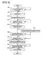
- FIG. 6 is a flowchart showing the flow of control performed in the idling stop control unit 17 and the power steering control unit 19.
- step S41 a determination is made as to whether or not a condition is fulfilled for stopping the engine and entering idling stop control.
- the process advances to step S42, and when the condition is not fulfilled, the determination of step S41 is repeated until the condition is fulfilled.
- the idling stop condition includes conditions such as the vehicle speed being zero, the accelerator pedal position being zero, the brake pedal being pressed, the engine oil or transmission oil being at least a predetermined temperature, and the battery voltage being at least a predetermined voltage, and when these conditions are all fulfilled, the idling stop condition is fulfilled.
- Other conditions may be added to the idling stop condition, which is not particularly limited.
- step S42 the supply of fuel to the engine is stopped, and the process advances to step S43.
- step S43 the assist motor 7 stops generating assist torque (steering assistance stops), and the process advances to step S44.
- step S44 a determination is made as to whether or not an idling stop cancel condition is fulfilled.
- the idling stop cancel condition includes conditions such as the accelerator pedal position being greater than zero, the pressing of the brake pedal having been lessened, the engine oil or the transmission oil being less than a predetermined temperature, and the battery voltage being less than a predetermined voltage, and when any of these conditions is fulfilled, the idling stop cancel condition is fulfilled.
- Other conditions may be added to the idling stop cancel condition, which is not particularly limited.
- step S45 the starter bypass relay 31 is turned on (opened), the engine 9 is cranked by the starter motor 11, and the process advances to step S46.
- step S46 a determination is made as to whether or not the starter bypass relay 31 has been switched from on (open) to off (closed).
- step S47 a switch has been made, the process advances to step S47, and when a switch has not been made, the process advances to step S51.
- step S47 a determination is made as to whether or not the battery voltage is at least a predetermined voltage.
- the process advances to step S48, and when the voltage is less than the predetermined voltage, the process advances to step S49.
- the predetermined voltage in step S47 is set to a power steering normal operating voltage (a voltage at which the assist motor 7 can stably generate sufficient assist torque).
- step S48 the assist motor 7 again begins to generate assist torque (steering assistance is restarted), and the process advances to step S51.
- step S49 a determination is made as to whether or not the engine 9 has reached complete combustion.
- the process advances to step S50, and when the engine has not reached complete combustion, this process is repeated.
- the determination that the engine 9 has reached complete combustion is made when the engine speed is equal to or greater than a speed that enables self-sustaining rotation (complete combustion determination speed: 500 [rpm], for example).
- step S50 the starter motor 11 ceases cranking the engine 9 and the process is ended.
- step S51 the assist motor 7 continues to not generate assist torque (steering assistance remains stopped), and the process advances to step S46.
- step S41 When the idling stop condition is fulfilled, the process advances from step S41 to step S42 and step S43, the supply of fuel to the engine is stopped, and steering assistance is stopped.
- step S44 the starter bypass relay 31 is turned on (opened), the starter motor 11 is operated, and the engine 9 is cranked.
- the starter bypass relay 31 When the idling stop cancel condition is fulfilled, the starter bypass relay 31 is switched from on (open) to off (closed), and the battery voltage is greater than the predetermined voltage, the process advances from step S47 to step S48 and steering assistance is restarted.
- step S49 When the engine 9 has reached complete combustion after steering assistance is restarted, the process transitions from step S49 to step S50, and the starter motor 11 ceases cranking the engine 9.
- FIG. 7 is a time chart showing the change in battery voltage before and after the engine is restarted.
- the starter bypass relay 31 When there is no starter bypass relay 31, the voltage rapidly decreases (instantly drops) the instant the starter motor 11 begins to crank the engine 9, as shown in FIG. 7 .
- the starter bypass relay 31 is provided between the battery 15 and the starter motor 11 in Embodiment 2.
- the starter bypass relay 31 When cranking is begun, the starter bypass relay 31 is turned on (opened) and electric current flowing from the battery 15 to the starter motor 11 passes through the resistor circuit 31 b. The instant drop in voltage at the start of cranking can thereby be suppressed as shown in FIG. 7 .
- the starter bypass relay 31 When a predetermined time elapses after the start of cranking, the starter bypass relay 31 is switched from on (open) to off (closed), the resistor circuit 31b is shorted, and the electric current flowing from the battery 15 to the starter motor 11 passes through the relay circuit 31 a.
- the resistor circuit 31b can thereby be kept from reaching a high temperature.
- steering assistance is stopped when the starter motor 11 begins cranking the engine 9 in Embodiment 2.
- Steering assistance remains stopped even immediately after the starter bypass relay 31 is switched from on (open) to off (closed), and steering assistance is restarted after the voltage of the battery 15 reaches the predetermined voltage or greater.
- FIG. 8 is a time chart from engine startup through an idling stop until the engine is restarted.
- FIG. 8(a) shows the engine speed
- FIG. 8(b) shows the operating state of the engine 9
- FIG. 8(c) shows the state of idling stop control
- FIG. 8(d) shows the operating state of the starter bypass relay 31
- FIG. 8(e) shows the state of steering assistance
- FIG. 8(f) shows the battery voltage.
- the ignition switch is operated and the engine 9 is cranked.
- the engine 9 is operated by the starter motor 11 at this time.
- the starter bypass relay 31 is switched from on (open) to off (closed).
- the resistor circuit 31b is thereby shorted, the electric current flowing from the battery 15 to the starter motor 11 passes through the relay circuit 31a, and the resistor circuit 31b can be kept from reaching a high temperature. Because the battery voltage decreases when the starter bypass relay 31 is switched from on (open) to off (closed), steering assistance continues to be prohibited (stopped) at the point in time of time t16.
- the battery voltage is at least a voltage that enables the assist motor 7 to generate assist torque, and steering assistance is therefore allowed (restarted).
- the engine speed is greater than the complete combustion determination speed (500 [rpm]), it is determined that the engine 9 has reached complete combustion, the starter motor 11 is stopped, and cranking is ended.
- Embodiment 2 The effects of Embodiment 2 are described.
- the starter bypass relay 31 (circuit switching means) for increasing the resistance of the power supply circuit when the engine 9 startup is initiated and reducing the resistance of the power supply circuit after the elapse of a predetermined time following initiation of the engine 9 startup is provided on the power supply circuit joining the battery 15 and the starter motor 11, and, after the initiation of engine startup and once the resistance of the power supply circuit has been switched by the starter bypass relay 31, the power steering control unit 19 determines that voltage fluctuation of the battery 15 is equal to or less than a predetermined voltage range when the voltage of the battery 15 is at least a predetermined voltage.
- the assist motor 7 is operated even while the starter motor 11 is operating (during cranking), and assist torque can therefore be quickly and stably outputted after idling stop control has been canceled.
- the starter bypass relay 31 is provided between the battery 15 and the starter motor 11.
- the battery 15 and the starter motor 11 are directly connected.
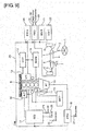
- FIG. 9 is a schematic diagram of a vehicle system equipped with power steering and idling stop.
- This vehicle system has, as a steering mechanism, a steering wheel 1, a steering shaft 2 connected to the steering wheel 1, a pinion 3 that rotates integrally with the steering shaft 2, a rack 4 for converting the rotational motion of the pinion 3 into linear motion in the vehicle width direction, tie rods 5 connected to both ends of the rack 4, and steered wheels 6 that are connected to the tie rods 5 and that perform steering in accordance with the steered amount of the steering wheel 1.
- the vehicle system also has, as a power-steering mechanism, an assist motor 7 for outputting assist torque that supplements the steering torque of the driver, and a pinion 8 that rotates integrally with a motor shaft of the assist motor 7 and meshes with the rack 4.
- the vehicle system also has an engine 9 as a drive source, and the drive force of the engine 9 is outputted to an automatic transmission 10.
- the engine 9 is provided with a starter motor 11 for cranking the engine 9 when the engine starts up.
- a compressor 13 connected via a belt with a crankshaft of the engine 9.
- the compressor 13, which is operated by the engine 9, compresses a catalyst of a cooler 12 for sending cold air into a passenger compartment.
- an alternator 30 connected via a belt with the crankshaft of the engine 9. After engine startup, the alternator 30 is operated by the engine 9 to generate power.
- the engine 9 is connected to a heater 16 for sending hot air into the passenger compartment, and the heater 16 utilizes the heat of the engine 9.
- the configuration of the control system includes an idling stop control unit 17, an automatic transmission control unit 18, and a power steering control unit 19. These along with other electronic control units 20, 21, 22 share information through a controller area network (CAN) 23.
- CAN controller area network
- a brake switch 24 for outputting information on whether or not a brake pedal is being operated
- a PN switch 25 for outputting information on whether or not the shift position is P (park) or N (neutral)
- an accelerator position sensor 26 for outputting information on an accelerator pedal position.
- An inhibitor switch 27 showing the shift position is connected to the automatic transmission control unit 18.
- a steering angle sensor 28 for detecting the steering angle of the steering wheel 1, and a steering torque sensor 29 for detecting the steering torque inputted to the steering wheel 1.
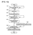
- FIG. 10 is a flowchart showing the flow of control performed in the idling stop control unit 17 and the power steering control unit 19.
- step S21 a determination is made as to whether or not a condition is fulfilled for stopping the engine and entering idling stop control.
- the process advances to step S22, and when the condition is not fulfilled, the determination of step S21 is repeated until the condition is fulfilled.
- the idling stop condition includes conditions such as the vehicle speed being zero, the accelerator pedal position being zero, the brake pedal being pressed, the engine oil or transmission oil being at least a predetermined temperature, and the battery voltage being at least a predetermined voltage, and when these conditions are all fulfilled, the idling stop condition is fulfilled.
- Other conditions may be added to the idling stop condition, which is not particularly limited.
- step S22 the supply of fuel to the engine is stopped, and the process advances to step S23.
- step S23 the assist motor 7 stops generating assist torque (steering assistance stops), and the process advances to step S24.
- step S24 a determination is made as to whether or not an idling stop cancel condition is fulfilled.
- the idling stop cancel condition includes conditions such as the accelerator pedal position being greater than zero, the pressing of the brake pedal having been lessened, the engine oil or the transmission oil being less than a predetermined temperature, and the battery voltage being less than a predetermined voltage, and when any of these conditions is fulfilled, the idling stop cancel condition is fulfilled.
- Other conditions may be added to the idling stop cancel condition, which is not particularly limited.
- step S25 the engine 9 is cranked by the starter motor 11, and the process advances to step S26.
- step S26 a determination is made as to whether or not the battery voltage is at least a predetermined voltage.
- the process advances to step S27, and when the battery voltage is less than the predetermined voltage, the process advances to step S28.
- the predetermined voltage in step S26 is set to a voltage that enables the assist motor 7 to generate assist torque.
- step S27 the assist motor 7 again begins to generate assist torque (steering assistance is restarted), and the process is ended.
- step S28 the assist motor 7 continues to not generate assist torque (steering assistance remains stopped), and the process advances to step S26.
- step S21 When the idling stop condition is fulfilled, the process advances from step S21 to step S22 and step S23, the supply of fuel to the engine is stopped, and steering assistance is stopped.
- step S24 the starter motor 11 is operated, and the engine 9 is cranked.
- step S26 the process advances from step S26 to step S28, and steering assistance remains stopped.
- step S26 When the idling stop cancel condition is fulfilled and the battery voltage is greater than the predetermined voltage, the process advances from step S26 to step S27 and steering assistance is restarted.
- the power steering control unit 19 determines that the voltage fluctuation of the battery 15 is equal to or less than the predetermined voltage range.
- the assist motor 7 is operated even while the starter motor 11 is operating (during cranking), and assist torque can therefore be quickly and stably outputted after idling stop control has been canceled.
- Embodiments 1 to 3 after the engine is restarted, steering assistance is restarted after the battery voltage is restored to a voltage that enables the assist motor 7 to generate assist torque.
- assist torque corresponding to the battery voltage is outputted even it is not possible for assist torque to be sufficiently generated by the assist motor 7.
- FIG. 11 is a flowchart showing the flow of control performed in the idling stop control unit 17 and the power steering control unit 19.
- step S31 a determination is made as to whether or not a condition is fulfilled for stopping the engine and entering idling stop control.
- the process advances to step S32, and when the condition is not fulfilled, the determination of step S31 is repeated until the condition is fulfilled.
- the idling stop condition includes conditions such as the vehicle speed being zero, the accelerator pedal position being zero, the brake pedal being pressed, the engine oil or transmission oil being at least a predetermined temperature, and the battery voltage being at least a predetermined voltage, and when these conditions are all fulfilled, the idling stop condition is fulfilled.
- Other conditions may be added to the idling stop condition, which is not particularly limited.
- step S32 the supply of fuel to the engine is stopped, and the process advances to step S33.
- step S33 the assist motor 7 stops generating assist torque (steering assistance stops), and the process advances to step S34.
- step S34 a determination is made as to whether or not an idling stop cancel condition is fulfilled.
- the idling stop cancel condition includes conditions such as the accelerator pedal position being greater than zero, the pressing of the brake pedal having been lessened, the engine oil or the transmission oil being less than a predetermined temperature, and the battery voltage being less than a predetermined voltage, and when any of these conditions is fulfilled, the idling stop cancel condition is fulfilled.
- Other conditions may be added to the idling stop cancel condition, which is not particularly limited.
- step S35 the engine 9 is cranked by the SSG 14, and the process advances to step S36.
- step S36 a determination is made as to whether or not the operation of the SSG 14 has ended, or in other words, whether or not cranking of the engine 9 has ended.
- the process advances to step S37, and when the operation has not ended, the process advances to step S40.
- the determination of step S36 may be made in place of the determination of whether or not the battery voltage fluctuation is equal to or less than the predetermined fluctuation range.
- the predetermined fluctuation range is preferably set on the basis of the fluctuation range that occurs when the SSG 14 is operating.
- step S37 the battery voltage is read, and the process advances to step S38.
- step S38 an assist torque is calculated that corresponds to the battery voltage and that can be outputted by the assist motor 7, and the process advances to step S39.
- the process of step S38 is performed until the battery voltage is restored to a voltage that enables the assist motor 7 to generate assist torque corresponding to the steering maneuver performed by the driver. After the battery voltage has been restored to a voltage that enables the assist motor 7 to generate assist torque corresponding to the steering maneuver performed by the driver, the assist torque is calculated according to the steering maneuver performed by the driver.
- step S39 the assist motor 7 is instructed to output the calculated assist torque, and the process is ended.
- step S40 the assist motor 7 continues to not generate assist torque (steering assistance remains stopped), and the process advances to step S36.
- step S31 When the idling stop condition is fulfilled, the process advances from step S31 to step S32 and step S33, the supply of fuel to the engine is stopped, and steering assistance is stopped.
- step S34 the SSG 14 is operated, and the engine 9 is cranked.
- step S36 When the SSG 14 is operating even after the idling stop cancel condition has been fulfilled, the process advances from step S36 to step S40, and steering assistance remains stopped.
- step S36 advances from step S37, step S38, and step S39, and assist torque corresponding to the battery voltage is outputted by the assist motor 7.
- Embodiment 4 when the voltage fluctuation of the battery 15 is equal to or less than the predetermined fluctuation range after engine startup, assist torque is calculated according to the battery voltage and the assist motor 7 is controlled so as to output the calculated assist torque. It is thereby possible for assist torque to be generated quickly although the assist torque is not great enough, and steering assistance can be performed for the steering of the driver.
- the power steering control unit 19 calculates assist torque corresponding to the voltage of the battery 15 and controls the assist motor 7 so as to output the calculated assist torque.
- assist torque can be generated quickly, and steering assistance can be performed for the steering of the driver.
- the present invention is not limited to the configurations of the above embodiments; other configurations can be adopted.
- the steering assistance is stopped with the engine stop initiation (idling stop initiation) being the point in time when the supply of fuel to the engine is stopped, but the steering assistance may be stopped with the engine stop initiation (idling stop initiation) being the point in time when the engine rotation stops.
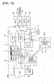
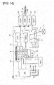
- Embodiments 1 through 4 systems equipped with the automatic transmission 10 are described, but the present invention may also be applied to a system equipped with a manual transmission 35 as shown in FIGS. 12 to 14 .
- a neutral switch 32 for outputting whether or not a shift lever is in a neutral position
- a lower clutch switch 33 for detecting that a lower clutch has been released (disengaged)
- an upper clutch switch 34 for detecting that an upper clutch is engaged (coupled).
- the lower clutch switch 33 outputs an on signal when the pressed amount of a clutch pedal is below a half clutch starting point.
- the upper clutch switch 34 outputs an on signal when the pressed amount of the clutch pedal is above the half clutch starting point.
Landscapes
- Engineering & Computer Science (AREA)
- Chemical & Material Sciences (AREA)
- Combustion & Propulsion (AREA)
- Mechanical Engineering (AREA)
- General Engineering & Computer Science (AREA)
- Transportation (AREA)
- Control Of Vehicle Engines Or Engines For Specific Uses (AREA)
- Power Steering Mechanism (AREA)
- Steering Control In Accordance With Driving Conditions (AREA)
- Control Of Driving Devices And Active Controlling Of Vehicle (AREA)
- Output Control And Ontrol Of Special Type Engine (AREA)
Abstract
Description
- The present invention relates to a vehicle control device.
-
Patent Document 1 listed below discloses a device in which power stops being supplied to an power steering motor in the event of a transition to an idling stop. - Patent Document 1: Japanese Laid-Open Patent Application No.
2010-248964 -
Patent Document 1 discloses no matter concerning the timing at which power start to be supplied once more to an power steering motor when an engine is restarted after an idling stop. After the engine has restarted, it has not always been possible to impart assist torque to the steering torque of the driver when the vehicle begins to move. - The present invention focuses on the above problem, it being an object of the invention to provide a vehicle control device that can quickly impart assist torque to the steering torque of the driver by means of a power-steering mechanism after the engine has restarted.
- In order to achieve the above objective, according to the present invention, when an engine is to be restarted, a power-steering mechanism is reactivated when voltage fluctuation of a battery is equal to or less than a predetermined fluctuation range after startup of the engine has been initiated.
- Consequently, the power-steering mechanism is reactivated while voltage fluctuation of the battery is stable, and assist torque can therefore be quickly and stably outputted after idling stop control has been canceled.
-
- [
Figure 1 ] Schematic diagram of a vehicle system ofEmbodiment 1. - [
Figure 2 ] Flowchart ofEmbodiment 1. - [
Figure 3 ] Time chart showing the change in battery voltage when the engine is restarted inEmbodiment 1. - [
Figure 4 ] Time chart from engine startup to an engine restart following an idling stop in Embodiment 1. - [
Figure 5 ] Schematic diagram of a vehicle system ofEmbodiment 2. - [
Figure 6 ] Flowchart ofEmbodiment 2. - [
Figure 7 ] Time chart showing the change in battery voltage when the engine is restarted inEmbodiment 2. - [
Figure 8 ] Time chart from engine startup to an engine restart following an idling stop in Embodiment 2. - [
Figure 9 ] Schematic diagram of a vehicle system ofEmbodiment 3. - [
Figure 10 ] Flowchart ofEmbodiment 3. - [
Figure 11 ] Flowchart ofEmbodiment 4. - [
Figure 12 ] Schematic diagram of a vehicle system of another embodiment. - [
Figure 13 ] Schematic diagram of a vehicle system of another embodiment. - [
Figure 14 ] Schematic diagram of a vehicle system of another embodiment. -
- 7 Assist motor (power-steering mechanism)
- 9 Engine
- 11 Starter motor (engine startup means)
- 14 SSG (engine startup means)
- 15 Battery
- 17 Idling stop control unit (idling stop control means)
- 19 Power steering control unit (power-steering control means)
- 31 Starter bypass relay (circuit switching means)
-
FIG. 1 is a schematic diagram of a vehicle system equipped with power steering and idling stop. - This vehicle system has, as a steering mechanism, a
steering wheel 1, asteering shaft 2 connected to thesteering wheel 1, apinion 3 that rotates integrally with thesteering shaft 2, arack 4 for converting the rotational motion of thepinion 3 into linear motion in the vehicle width direction,tie rods 5 connected to both ends of therack 4, and steeredwheels 6 that are connected to thetie rods 5 and that perform steering in accordance with the steered amount of thesteering wheel 1. The vehicle system also has, as a power-steering mechanism, anassist motor 7 for outputting assist torque that supplements the steering torque of the driver, and apinion 8 that rotates integrally with a motor shaft of theassist motor 7 and meshes with therack 4. - The vehicle system also has an
engine 9 as a drive source, and the drive force of theengine 9 is outputted to anautomatic transmission 10. Theengine 9 is provided with astarter motor 11 for cranking theengine 9 when the engine starts up. Also provided is acompressor 13 connected via a belt with a crankshaft of theengine 9. Thecompressor 13, which is operated by theengine 9, compresses a catalyst of acooler 12 for sending cold air into a passenger compartment. Also provided is a side mounted starter generator (SSG) 14 connected via a belt with the crankshaft of theengine 9. The SSG 14 cranks theengine 9 when the engine starts up, and the SSG is operated by theengine 9 to generate power after the engine has started up. Thestarter motor 11 and the SSG 14, which are connected to abattery 15, use the power of thebattery 15 to crank the engine when the engine starts up. The SSG 14 stores the power generated after the engine has started up in thebattery 15. Theengine 9 is connected to aheater 16 for sending hot air into the passenger compartment, and theheater 16 utilizes the heat of theengine 9. - The configuration of the control system includes an idling
stop control unit 17, an automatictransmission control unit 18, and a powersteering control unit 19. These along with otherelectronic control units - Connected to the idling
stop control unit 17 are abrake switch 24 for outputting information on whether or not a brake pedal is being operated, aPN switch 25 for outputting information on whether or not the shift position is P (park) or N (neutral), and anaccelerator position sensor 26 for outputting information on an accelerator pedal position. Aninhibitor switch 27 showing the shift position is connected to the automatictransmission control unit 18. Connected to the powersteering control unit 19 are asteering angle sensor 28 for detecting the steering angle of thesteering wheel 1, and asteering torque sensor 29 for detecting the steering torque inputted to thesteering wheel 1. - Next, idling stop control is described.
FIG. 2 is a flowchart showing the flow of control performed in the idlingstop control unit 17 and the powersteering control unit 19. - In step S1, a determination is made as to whether or not a condition is fulfilled for stopping the engine and entering idling stop control. When the condition is fulfilled, the process advances to step S2, and when the condition is not fulfilled, the determination of step S1 is repeated until the condition is fulfilled. The idling stop condition includes conditions such as the vehicle speed being zero, the accelerator pedal position being zero, the brake pedal being pressed, the engine oil or transmission oil being at least a predetermined temperature, and the battery voltage being at least a predetermined voltage, and when these conditions are all fulfilled, the idling stop condition is fulfilled. Other conditions may be added to the idling stop condition, which is not particularly limited.
- In step S2, the supply of fuel to the engine is stopped, and the process advances to step S3. The language "engine stop" or "the engine stops" hereinafter refers to a state in which the supply of fuel to the engine has stopped, and, as shall be apparent, includes states in which the engine is not turning, but also includes states in which the supply of fuel has stopped and the engine is turning by inertia.
- In step S3, the
assist motor 7 stops generating assist torque (steering assistance stops), and the process advances to step S4. - In step S4, a determination is made as to whether or not an idling stop cancel condition is fulfilled. When the condition is fulfilled, the process advances to step S5, and when the condition is not fulfilled, the determination of step S4 is repeated until the condition is fulfilled. The idling stop cancel condition includes conditions such as the accelerator pedal position being greater than zero, the pressing of the brake pedal having been lessened, the engine oil or the transmission oil being less than a predetermined temperature, and the battery voltage being less than a predetermined voltage, and when any of these conditions is fulfilled, the idling stop cancel condition is fulfilled. Other conditions may be added to the idling stop cancel condition, which is not particularly limited.
- In step S5, the
engine 9 is cranked by theSSG 14, and the process advances to step S6. - In step S6, a determination is made as to whether or not the operation of the
SSG 14 has ended. When the operation has ended, the process advances to step S7, and when the operation has not ended, the process advances to step S8. TheSSG 14 ends operation when it is determined that theengine 9 has reached complete combustion. The determination that theengine 9 has reached complete combustion is made when the engine speed is equal to or greater than a speed that enables self-sustaining rotation (complete combustion determination speed: 500 [rpm], for example). With the determination that the operation of theSSG 14 has ended, the voltage fluctuation of thebattery 15 can be determined to be equal to or less than the predetermined fluctuation range. - In step S7, the
assist motor 7 begins again to generate assist torque (steering assistance is restarted), and the process is ended. - In step S8, the
assist motor 7 continues to not generate assist torque (the stopping of steering assistance is continued), and the process advances to step S6. - When the idling stop condition is fulfilled, the process advances from step S1 to step S2 and step S3, the supply of fuel to the engine is stopped, and steering assistance is stopped.
- After the engine stop (idling stop), when the idling stop cancel condition is fulfilled, the process advances from step S4 to step S5, the
SSG 14 is operated, and theengine 9 is cranked. - When the
SSG 14 is operating even after the idling stop cancel condition has been fulfilled, the process advances from step S6 to step S8, and steering assistance remains stopped. - When the idling stop cancel condition has been fulfilled and operation of the
SSG 14 is ended, the process advances from step S6 to step S7 and steering assistance is restarted. - Due to steering assistance being stopped when the idling stop condition is fulfilled, power consumption of the
battery 15 can be suppressed. Due to steering assistance being restarted when the idling stop is canceled, assist torque can be generated for the steering torque of the driver when travel is restarted. - When the idling stop cancel condition is fulfilled, the
engine 9 is started up by theSSG 14. TheSSG 14 uses the power of thebattery 15 when cranking theengine 9.FIG. 3 is a time chart showing the change in battery voltage before and after the battery is restarted. When theSSG 14 cranks theengine 9, the voltage fluctuation is greater than before and after cranking, as shown inFIG. 3 . Therefore, during cranking, the voltage is sometimes equal to or less than a power steering normal operating voltage (a voltage at which theassist motor 7 can stably generate sufficient assist torque). - In view of this, in
Embodiment 1, steering assistance remains stopped when theSSG 14 is operating and the battery voltage fluctuation is large, and steering assistance is restarted after theSSG 14 stops and the battery voltage fluctuation decreases. -
FIG. 4 is a time chart from engine startup through an idling stop until an engine restart.FIG. 4(a) shows the engine speed,FIG. 4(b) shows the operating state of theengine 9,FIG. 4(c) shows the state of idling stop control,FIG. 4(d) shows the operating state of theSSG 14,FIG. 4(e) shows the state of steering assistance, andFIG. 4(f) shows the battery voltage. - At time t1, the ignition switch is operated and the
engine 9 is cranked. Theengine 9 is operated by thestarter motor 11 at this time. - At time t2, cranking by the
starter motor 11 ends and self-sustained rotation of theengine 9 is begun. - At time t3, the supply of fuel to the engine is stopped because idling stop control is initiated when the idling stop condition is fulfilled. Steering assistance is also prohibited (stopped).
- At time t4, the engine rotation stops.
- At time t5, when the idling stop cancel condition is fulfilled, such as, for example, the pressing of the brake pedal being released, idling stop control is canceled, and the
engine 9 is cranked by theSSG 14. - When the engine has reached complete combustion at time t6, the
SSG 14 ends operation, the battery voltage fluctuation decreases, and the battery voltage becomes equal to or greater than the power steering normal operating voltage. Therefore, steering assistance is allowed (restarted). - The effects of
Embodiment 1 are described. - (1) The vehicle control comprises the assist motor 7 (power-steering mechanism) for imparting assist torque to steering torque of a driver, the SSG 14 (engine startup means) for using the power of the
battery 15 to start up theengine 9, the idling stop control unit 17 (idling stop control means) for stopping theengine 9 when the vehicle stops and restarting theengine 9 when the vehicle begins to move, and the power steering control unit 19 (power-steering control means) for controlling theassist motor 7 so as to generate assist torque corresponding to the steering maneuver performed by the driver; wherein the powersteering control unit 19 stops generating the assist torque through theassist motor 7 when theengine 9 has stopped, and reactivates theassist motor 7 when fluctuation in thebattery voltage 15 is equal to or less than a predetermined fluctuation range, afterengine 9 startup has been initiated when theengine 9 is being restarted.
Consequently, theassist motor 7 is operated while the voltage fluctuation of thebattery 15 is stable, and assist torque can therefore be quickly and stably outputted after the idling stop control has been canceled. - (2) The power
steering control unit 19 determines that the voltage fluctuation of thebattery 15 is equal to or less than the predetermined fluctuation range when theengine 9 startup is complete and theSSG 14 has stopped.
Consequently, theassist motor 7 is operated when the voltage of thebattery 15 has been sufficiently restored, and assist torque can therefore be quickly and sufficiently outputted after the idling stop control has been canceled. - In
Embodiment 1, theengine 9 is cranked by theSSG 14 when the engine is restarted after idling stop control is canceled. InEmbodiment 2, theengine 9 is cranked by thestarter motor 11 even when the engine is restarted after idling stop control is canceled. InEmbodiment 2, astarter bypass relay 31 is provided between thebattery 15 and thestarter motor 11. -
FIG. 5 is a schematic diagram of a vehicle system equipped with power steering and idling stop. - This vehicle system has, as a steering mechanism, a
steering wheel 1, asteering shaft 2 connected to thesteering wheel 1, apinion 3 that rotates integrally with thesteering shaft 2, arack 4 for converting the rotational motion of thepinion 3 into linear motion in the vehicle width direction,tie rods 5 connected to both ends of therack 4, and steeredwheels 6 that are connected to thetie rods 5 and that perform steering in accordance with the steered amount of thesteering wheel 1. The vehicle system also has, as a power-steering mechanism, anassist motor 7 for outputting assist torque that supplements the steering torque of the driver, and apinion 8 that rotates integrally with a motor shaft of theassist motor 7 and meshes with therack 4. - The vehicle system also has an
engine 9 as a drive source, and the drive force of theengine 9 is outputted to anautomatic transmission 10. Theengine 9 is provided with astarter motor 11 for cranking theengine 9 when the engine starts up. Also provided is acompressor 13 connected via a belt with a crankshaft of theengine 9. Thecompressor 13, which is operated by theengine 9, compresses a catalyst of a cooler 12 for sending cold air into a passenger compartment. Also provided is analternator 30 connected via a belt with the crankshaft of theengine 9. After engine startup, thealternator 30 is operated by theengine 9 to generate power. - The
starter bypass relay 31 is provided between thestarter motor 11 and thebattery 15. Thestarter bypass relay 31 is configured from arelay circuit 31a and aresistor circuit 31b provided in parallel to therelay circuit 31a. Normally, thestarter bypass relay 31 is off and therelay circuit 31a is closed. At this time, electric current flows through therelay circuit 31a and does not flow to theresistor circuit 31b. When the engine is cranked by thestarter motor 11, thestarter bypass relay 31 is turned on and therelay circuit 31a is opened. At this time, electric current does not flow to therelay circuit 31 b and does flow through theresistor circuit 31b. - The
engine 9 is connected to aheater 16 for sending hot air into the passenger compartment, and theheater 16 utilizes the heat of theengine 9. - The configuration of the control system includes an idling
stop control unit 17, an automatictransmission control unit 18, and a powersteering control unit 19. These along with otherelectronic control units - Connected to the idling
stop control unit 17 are abrake switch 24 for outputting information on whether or not a brake pedal is being operated, aPN switch 25 for outputting information on whether or not the shift position is P (park) or N (neutral), and anaccelerator position sensor 26 for outputting information on an accelerator pedal position. Aninhibitor switch 27 showing the shift position is connected to the automatictransmission control unit 18. Connected to the powersteering control unit 19 are asteering angle sensor 28 for detecting the steering angle of thesteering wheel 1, and asteering torque sensor 29 for detecting the steering torque inputted to thesteering wheel 1. - Next, idling stop control is described.
FIG. 6 is a flowchart showing the flow of control performed in the idlingstop control unit 17 and the powersteering control unit 19. - In step S41, a determination is made as to whether or not a condition is fulfilled for stopping the engine and entering idling stop control. When the condition is fulfilled, the process advances to step S42, and when the condition is not fulfilled, the determination of step S41 is repeated until the condition is fulfilled. The idling stop condition includes conditions such as the vehicle speed being zero, the accelerator pedal position being zero, the brake pedal being pressed, the engine oil or transmission oil being at least a predetermined temperature, and the battery voltage being at least a predetermined voltage, and when these conditions are all fulfilled, the idling stop condition is fulfilled. Other conditions may be added to the idling stop condition, which is not particularly limited.
- In step S42, the supply of fuel to the engine is stopped, and the process advances to step S43.
- In step S43, the
assist motor 7 stops generating assist torque (steering assistance stops), and the process advances to step S44. - In step S44, a determination is made as to whether or not an idling stop cancel condition is fulfilled. When the condition is fulfilled, the process advances to step S45, and when the condition is not fulfilled, the determination of step S44 is repeated until the condition is fulfilled. The idling stop cancel condition includes conditions such as the accelerator pedal position being greater than zero, the pressing of the brake pedal having been lessened, the engine oil or the transmission oil being less than a predetermined temperature, and the battery voltage being less than a predetermined voltage, and when any of these conditions is fulfilled, the idling stop cancel condition is fulfilled. Other conditions may be added to the idling stop cancel condition, which is not particularly limited.
- In step S45, the
starter bypass relay 31 is turned on (opened), theengine 9 is cranked by thestarter motor 11, and the process advances to step S46. - In step S46, a determination is made as to whether or not the
starter bypass relay 31 has been switched from on (open) to off (closed). When a switch has been made, the process advances to step S47, and when a switch has not been made, the process advances to step S51. - In step S47, a determination is made as to whether or not the battery voltage is at least a predetermined voltage. When the voltage is at least the predetermined voltage, the process advances to step S48, and when the voltage is less than the predetermined voltage, the process advances to step S49. The predetermined voltage in step S47 is set to a power steering normal operating voltage (a voltage at which the
assist motor 7 can stably generate sufficient assist torque). - In step S48, the
assist motor 7 again begins to generate assist torque (steering assistance is restarted), and the process advances to step S51. - In step S49, a determination is made as to whether or not the
engine 9 has reached complete combustion. When the engine has reached complete combustion, the process advances to step S50, and when the engine has not reached complete combustion, this process is repeated. The determination that theengine 9 has reached complete combustion is made when the engine speed is equal to or greater than a speed that enables self-sustaining rotation (complete combustion determination speed: 500 [rpm], for example). - In step S50, the
starter motor 11 ceases cranking theengine 9 and the process is ended. - In step S51, the
assist motor 7 continues to not generate assist torque (steering assistance remains stopped), and the process advances to step S46. - When the idling stop condition is fulfilled, the process advances from step S41 to step S42 and step S43, the supply of fuel to the engine is stopped, and steering assistance is stopped.
- After the engine stop (idling stop), when the idling stop cancel condition is fulfilled, the process advances from step S44 to step S45, the
starter bypass relay 31 is turned on (opened), thestarter motor 11 is operated, and theengine 9 is cranked. - Even after the idling stop cancel condition has been fulfilled, when the
starter bypass relay 31 is turned on (opened), the process advances from step S46 to step S51, and steering assistance remains stopped. - Furthermore, even after the
starter bypass relay 31 has been switched from on (open) to off (closed), when the battery voltage is equal to or less than the predetermined voltage, the process advances from step S47 to step S51, and steering assistance remains stopped. - When the idling stop cancel condition is fulfilled, the
starter bypass relay 31 is switched from on (open) to off (closed), and the battery voltage is greater than the predetermined voltage, the process advances from step S47 to step S48 and steering assistance is restarted. - When the
engine 9 has reached complete combustion after steering assistance is restarted, the process transitions from step S49 to step S50, and thestarter motor 11 ceases cranking theengine 9. - Due to steering assistance being stopped when the idling stop condition is fulfilled, power consumption of the
battery 15 can be suppressed. Due to steering assistance being restarted when the idling stop is canceled, assist torque can be generated for the steering torque of the driver when travel is restarted. - When the idling stop condition is fulfilled, the
starter bypass relay 31 turns on and theengine 9 is started up by thestarter motor 11.FIG. 7 is a time chart showing the change in battery voltage before and after the engine is restarted. - When there is no
starter bypass relay 31, the voltage rapidly decreases (instantly drops) the instant thestarter motor 11 begins to crank theengine 9, as shown inFIG. 7 . In view of this, thestarter bypass relay 31 is provided between thebattery 15 and thestarter motor 11 inEmbodiment 2. When cranking is begun, thestarter bypass relay 31 is turned on (opened) and electric current flowing from thebattery 15 to thestarter motor 11 passes through theresistor circuit 31 b. The instant drop in voltage at the start of cranking can thereby be suppressed as shown inFIG. 7 . - When a predetermined time elapses after the start of cranking, the
starter bypass relay 31 is switched from on (open) to off (closed), theresistor circuit 31b is shorted, and the electric current flowing from thebattery 15 to thestarter motor 11 passes through therelay circuit 31 a. Theresistor circuit 31b can thereby be kept from reaching a high temperature. - When the
starter bypass relay 31 is switched from on (open) to off (closed), the voltage fluctuation increases, and the voltage fluctuates between point A and point B inFIG. 7 . The voltage is thereafter gradually restored. In other words, immediately after thestarter bypass relay 31 is switched from on (open) to off (closed), though theassist motor 7 attempts to generate assist torque, there is a risk that generating sufficient assist torque will not be possible. - In view of this, steering assistance is stopped when the
starter motor 11 begins cranking theengine 9 inEmbodiment 2. Steering assistance remains stopped even immediately after thestarter bypass relay 31 is switched from on (open) to off (closed), and steering assistance is restarted after the voltage of thebattery 15 reaches the predetermined voltage or greater. -
FIG. 8 is a time chart from engine startup through an idling stop until the engine is restarted.FIG. 8(a) shows the engine speed,FIG. 8(b) shows the operating state of theengine 9,FIG. 8(c) shows the state of idling stop control,FIG. 8(d) shows the operating state of thestarter bypass relay 31,FIG. 8(e) shows the state of steering assistance, andFIG. 8(f) shows the battery voltage. - At time t11, the ignition switch is operated and the
engine 9 is cranked. Theengine 9 is operated by thestarter motor 11 at this time. - At time t12, cranking by the
starter motor 11 ends and self-sustained rotation of theengine 9 is begun. - At time t13, the supply of fuel to the engine is stopped because idling stop control is initiated when the idling stop condition is fulfilled. Steering assistance is also prohibited (stopped).
- At time t14, the engine rotation stops.
- At time t15, when the idling stop cancel condition is fulfilled, for example, such as the pressing of the brake pedal being released, idling stop control is canceled, and the
engine 9 is cranked by thestarter motor 11. At this time, thebypass relay 13 is turned on (opened). The electric current flowing from thebattery 15 to thestarter motor 11 thereby passes through theresistor circuit 31 b, and the instant drop in voltage at the start of cranking can be suppressed. - At time t16, when a predetermined time has elapsed after the start of cranking, the
starter bypass relay 31 is switched from on (open) to off (closed). Theresistor circuit 31b is thereby shorted, the electric current flowing from thebattery 15 to thestarter motor 11 passes through therelay circuit 31a, and theresistor circuit 31b can be kept from reaching a high temperature. Because the battery voltage decreases when thestarter bypass relay 31 is switched from on (open) to off (closed), steering assistance continues to be prohibited (stopped) at the point in time of time t16. - At time t17, the battery voltage is at least a voltage that enables the
assist motor 7 to generate assist torque, and steering assistance is therefore allowed (restarted). - At time t18, the engine speed is greater than the complete combustion determination speed (500 [rpm]), it is determined that the
engine 9 has reached complete combustion, thestarter motor 11 is stopped, and cranking is ended. - The effects of
Embodiment 2 are described. - (3) The starter bypass relay 31 (circuit switching means) for increasing the resistance of the power supply circuit when the
engine 9 startup is initiated and reducing the resistance of the power supply circuit after the elapse of a predetermined time following initiation of theengine 9 startup is provided on the power supply circuit joining thebattery 15 and thestarter motor 11, and, after the initiation of engine startup and once the resistance of the power supply circuit has been switched by thestarter bypass relay 31, the powersteering control unit 19 determines that voltage fluctuation of thebattery 15 is equal to or less than a predetermined voltage range when the voltage of thebattery 15 is at least a predetermined voltage. - Consequently, the
assist motor 7 is operated even while thestarter motor 11 is operating (during cranking), and assist torque can therefore be quickly and stably outputted after idling stop control has been canceled. - In
Embodiment 2, thestarter bypass relay 31 is provided between thebattery 15 and thestarter motor 11. InEmbodiment 3, thebattery 15 and thestarter motor 11 are directly connected. -
FIG. 9 is a schematic diagram of a vehicle system equipped with power steering and idling stop. - This vehicle system has, as a steering mechanism, a
steering wheel 1, asteering shaft 2 connected to thesteering wheel 1, apinion 3 that rotates integrally with thesteering shaft 2, arack 4 for converting the rotational motion of thepinion 3 into linear motion in the vehicle width direction,tie rods 5 connected to both ends of therack 4, and steeredwheels 6 that are connected to thetie rods 5 and that perform steering in accordance with the steered amount of thesteering wheel 1. The vehicle system also has, as a power-steering mechanism, anassist motor 7 for outputting assist torque that supplements the steering torque of the driver, and apinion 8 that rotates integrally with a motor shaft of theassist motor 7 and meshes with therack 4. - The vehicle system also has an
engine 9 as a drive source, and the drive force of theengine 9 is outputted to anautomatic transmission 10. Theengine 9 is provided with astarter motor 11 for cranking theengine 9 when the engine starts up. Also provided is acompressor 13 connected via a belt with a crankshaft of theengine 9. Thecompressor 13, which is operated by theengine 9, compresses a catalyst of a cooler 12 for sending cold air into a passenger compartment. Also provided is analternator 30 connected via a belt with the crankshaft of theengine 9. After engine startup, thealternator 30 is operated by theengine 9 to generate power. Theengine 9 is connected to aheater 16 for sending hot air into the passenger compartment, and theheater 16 utilizes the heat of theengine 9. - The configuration of the control system includes an idling
stop control unit 17, an automatictransmission control unit 18, and a powersteering control unit 19. These along with otherelectronic control units - Connected to the idling
stop control unit 17 are abrake switch 24 for outputting information on whether or not a brake pedal is being operated, aPN switch 25 for outputting information on whether or not the shift position is P (park) or N (neutral), and anaccelerator position sensor 26 for outputting information on an accelerator pedal position. Aninhibitor switch 27 showing the shift position is connected to the automatictransmission control unit 18. Connected to the powersteering control unit 19 are asteering angle sensor 28 for detecting the steering angle of thesteering wheel 1, and asteering torque sensor 29 for detecting the steering torque inputted to thesteering wheel 1. - Next, idling stop control is described.
FIG. 10 is a flowchart showing the flow of control performed in the idlingstop control unit 17 and the powersteering control unit 19. - In step S21, a determination is made as to whether or not a condition is fulfilled for stopping the engine and entering idling stop control. When the condition is fulfilled, the process advances to step S22, and when the condition is not fulfilled, the determination of step S21 is repeated until the condition is fulfilled. The idling stop condition includes conditions such as the vehicle speed being zero, the accelerator pedal position being zero, the brake pedal being pressed, the engine oil or transmission oil being at least a predetermined temperature, and the battery voltage being at least a predetermined voltage, and when these conditions are all fulfilled, the idling stop condition is fulfilled. Other conditions may be added to the idling stop condition, which is not particularly limited.
- In step S22, the supply of fuel to the engine is stopped, and the process advances to step S23.
- In step S23, the
assist motor 7 stops generating assist torque (steering assistance stops), and the process advances to step S24. - In step S24, a determination is made as to whether or not an idling stop cancel condition is fulfilled. When the condition is fulfilled, the process advances to step S25, and when the condition is not fulfilled, the determination of step S24 is repeated until the condition is fulfilled. The idling stop cancel condition includes conditions such as the accelerator pedal position being greater than zero, the pressing of the brake pedal having been lessened, the engine oil or the transmission oil being less than a predetermined temperature, and the battery voltage being less than a predetermined voltage, and when any of these conditions is fulfilled, the idling stop cancel condition is fulfilled. Other conditions may be added to the idling stop cancel condition, which is not particularly limited.
- In step S25, the
engine 9 is cranked by thestarter motor 11, and the process advances to step S26. - In step S26, a determination is made as to whether or not the battery voltage is at least a predetermined voltage. When the battery voltage is at least the predetermined voltage, the process advances to step S27, and when the battery voltage is less than the predetermined voltage, the process advances to step S28. The predetermined voltage in step S26 is set to a voltage that enables the
assist motor 7 to generate assist torque. - In step S27, the
assist motor 7 again begins to generate assist torque (steering assistance is restarted), and the process is ended. - In step S28, the
assist motor 7 continues to not generate assist torque (steering assistance remains stopped), and the process advances to step S26. - When the idling stop condition is fulfilled, the process advances from step S21 to step S22 and step S23, the supply of fuel to the engine is stopped, and steering assistance is stopped.
- After the engine stop (idling stop), when the idling stop cancel condition is fulfilled, the process advances from step S24 to step S25, the
starter motor 11 is operated, and theengine 9 is cranked. - Even after the idling stop cancel condition has been fulfilled, when the battery voltage is equal to or less than the predetermined voltage, the process advances from step S26 to step S28, and steering assistance remains stopped.
- When the idling stop cancel condition is fulfilled and the battery voltage is greater than the predetermined voltage, the process advances from step S26 to step S27 and steering assistance is restarted.
- Due to steering assistance being stopped when the idling stop condition is fulfilled, power consumption of the
battery 15 can be suppressed. Due to steering assistance being restarted when the idling stop is canceled, assist torque can be generated for the steering torque of the driver when travel is restarted. - When the idling stop condition is fulfilled, the
engine 9 is started up by thestarter motor 11. Although the battery voltage fluctuates widely immediately after thestarter motor 11 cranks theengine 9, the fluctuation lessens as the battery voltage is restored, as shown inFIG. 7 ofEmbodiment 2. In other words, large voltage fluctuations do not occur while the battery voltage is being restored at times such as when thestarter bypass relay 31 is switched from on (open) to off (closed), as inEmbodiment 2. - In view of this, in
Embodiment 3, steering assistance remains stopped when the battery voltage is less than the predetermined voltage, and steering assistance is restarted when the battery voltage is at least the predetermined voltage. - The effects of
Embodiment 3 are described. - (4) After engine startup is initiated, when the voltage of the
battery 15 is at least the predetermined voltage, the powersteering control unit 19 determines that the voltage fluctuation of thebattery 15 is equal to or less than the predetermined voltage range. - Consequently, the
assist motor 7 is operated even while thestarter motor 11 is operating (during cranking), and assist torque can therefore be quickly and stably outputted after idling stop control has been canceled. - In
Embodiments 1 to 3, after the engine is restarted, steering assistance is restarted after the battery voltage is restored to a voltage that enables theassist motor 7 to generate assist torque. InEmbodiment 4, assist torque corresponding to the battery voltage is outputted even it is not possible for assist torque to be sufficiently generated by theassist motor 7. - A system in which the engine is restarted by the
SSG 14 is described below, but this embodiment can be similarly carried out in a system in which the engine is restarted by thestarter motor 11 with thestarter bypass relay 31 ofEmbodiment 2, or system in which the engine is restarted by thestarter motor 11 without thestarter bypass relay 31 as inEmbodiment 3. - In the following description, the system configuration is the same as that of
Embodiment 1, and the same configurations are therefore denoted with the same symbols and are not described. - Idling stop control is described.
FIG. 11 is a flowchart showing the flow of control performed in the idlingstop control unit 17 and the powersteering control unit 19. - In step S31, a determination is made as to whether or not a condition is fulfilled for stopping the engine and entering idling stop control. When the condition is fulfilled, the process advances to step S32, and when the condition is not fulfilled, the determination of step S31 is repeated until the condition is fulfilled. The idling stop condition includes conditions such as the vehicle speed being zero, the accelerator pedal position being zero, the brake pedal being pressed, the engine oil or transmission oil being at least a predetermined temperature, and the battery voltage being at least a predetermined voltage, and when these conditions are all fulfilled, the idling stop condition is fulfilled. Other conditions may be added to the idling stop condition, which is not particularly limited.
- In step S32, the supply of fuel to the engine is stopped, and the process advances to step S33.
- In step S33, the
assist motor 7 stops generating assist torque (steering assistance stops), and the process advances to step S34. - In step S34, a determination is made as to whether or not an idling stop cancel condition is fulfilled. When the condition is fulfilled, the process advances to step S35, and when the condition is not fulfilled, the determination of step S34 is repeated until the condition is fulfilled. The idling stop cancel condition includes conditions such as the accelerator pedal position being greater than zero, the pressing of the brake pedal having been lessened, the engine oil or the transmission oil being less than a predetermined temperature, and the battery voltage being less than a predetermined voltage, and when any of these conditions is fulfilled, the idling stop cancel condition is fulfilled. Other conditions may be added to the idling stop cancel condition, which is not particularly limited.
- In step S35, the
engine 9 is cranked by theSSG 14, and the process advances to step S36. - In step S36, a determination is made as to whether or not the operation of the
SSG 14 has ended, or in other words, whether or not cranking of theengine 9 has ended. When the operation has ended, the process advances to step S37, and when the operation has not ended, the process advances to step S40. The determination of step S36 may be made in place of the determination of whether or not the battery voltage fluctuation is equal to or less than the predetermined fluctuation range. The predetermined fluctuation range is preferably set on the basis of the fluctuation range that occurs when theSSG 14 is operating. - In step S37, the battery voltage is read, and the process advances to step S38.
- In step S38, an assist torque is calculated that corresponds to the battery voltage and that can be outputted by the
assist motor 7, and the process advances to step S39. The process of step S38 is performed until the battery voltage is restored to a voltage that enables theassist motor 7 to generate assist torque corresponding to the steering maneuver performed by the driver. After the battery voltage has been restored to a voltage that enables theassist motor 7 to generate assist torque corresponding to the steering maneuver performed by the driver, the assist torque is calculated according to the steering maneuver performed by the driver. - In step S39, the
assist motor 7 is instructed to output the calculated assist torque, and the process is ended. - In step S40, the
assist motor 7 continues to not generate assist torque (steering assistance remains stopped), and the process advances to step S36. - When the idling stop condition is fulfilled, the process advances from step S31 to step S32 and step S33, the supply of fuel to the engine is stopped, and steering assistance is stopped.
- After the engine stop (idling stop), when the idling stop cancel condition is fulfilled, the process advances from step S34 to step S35, the
SSG 14 is operated, and theengine 9 is cranked. - When the
SSG 14 is operating even after the idling stop cancel condition has been fulfilled, the process advances from step S36 to step S40, and steering assistance remains stopped. - When operation of the
SSG 14 has ended, the process advances from step S36 to step S37, step S38, and step S39, and assist torque corresponding to the battery voltage is outputted by theassist motor 7. - Immediately after the engine is restarted (immediately after operation of the
SSG 14 has ended), the battery voltage decreases and sufficient assist torque cannot be outputted by theassist motor 7. However, it is possible that the engine could have already restarted and the driver could begin steering. The reactive forces of both the road surface and steering are great when the vehicle is stopped or when the vehicle is moving at a low speed, and it is therefore preferable for assist torque to be outputted quickly by theassist motor 7 and for steering assistance to be performed for the steering of the driver. - In view of this, in
Embodiment 4, when the voltage fluctuation of thebattery 15 is equal to or less than the predetermined fluctuation range after engine startup, assist torque is calculated according to the battery voltage and theassist motor 7 is controlled so as to output the calculated assist torque. It is thereby possible for assist torque to be generated quickly although the assist torque is not great enough, and steering assistance can be performed for the steering of the driver. - The effects of
Embodiment 4 are described. - (5) After engine startup and after the voltage fluctuation of the
battery 15 has become equal to or less than the predetermined fluctuation range, the powersteering control unit 19 calculates assist torque corresponding to the voltage of thebattery 15 and controls theassist motor 7 so as to output the calculated assist torque. - Consequently, assist torque can be generated quickly, and steering assistance can be performed for the steering of the driver.
- The present invention is not limited to the configurations of the above embodiments; other configurations can be adopted. For example, in
Embodiments 1 through 4, the steering assistance is stopped with the engine stop initiation (idling stop initiation) being the point in time when the supply of fuel to the engine is stopped, but the steering assistance may be stopped with the engine stop initiation (idling stop initiation) being the point in time when the engine rotation stops. - In
Embodiments 1 through 4, systems equipped with theautomatic transmission 10 are described, but the present invention may also be applied to a system equipped with amanual transmission 35 as shown inFIGS. 12 to 14 . - In the case of a manual transmission, connected to the idling
stop control unit 17 are a neutral switch 32 for outputting whether or not a shift lever is in a neutral position, a lower clutch switch 33 for detecting that a lower clutch has been released (disengaged), and an upperclutch switch 34 for detecting that an upper clutch is engaged (coupled). The lower clutch switch 33 outputs an on signal when the pressed amount of a clutch pedal is below a half clutch starting point. The upperclutch switch 34 outputs an on signal when the pressed amount of the clutch pedal is above the half clutch starting point.
Claims (5)
- A vehicle control device characterized by comprising:a power-steering mechanism for imparting assist torque to steering torque of a driver;engine startup means for using battery power to start up the engine;idling stop control means for stopping the engine when the vehicle stops and restarting the engine when the vehicle begins to move; andpower-steering control means for controlling the power-steering mechanism so as to generate assist torque corresponding to the steering maneuver performed by the driver;the power-steering control means causing generating of the assist torque through the power-steering mechanism to be stopped when the engine has stopped, and, when the engine is restarted, causing the power-steering mechanism to be reactivated when fluctuation in the battery voltage after engine startup has been initiated is equal to or less than a predetermined fluctuation range.
- The vehicle control device according to claim 1, characterized in that:the power-steering control means determines that the voltage fluctuation of the battery is equal to or less than the predetermined fluctuation range when the engine startup is complete and the engine startup means has stopped.
- The vehicle control device according to claim 1, characterized by comprising:circuit switching means for increasing the resistance of a power supply circuit joining the battery and the engine startup means when the engine startup is initiated and reducing the resistance of the power supply circuit after a predetermined time has elapsed after the engine startup is initiated, the circuit switching means being located on the power supply circuit;the power-steering control means determining that the voltage fluctuation of the battery is equal to or less than a predetermined fluctuation range when the voltage of the battery is at least a predetermined voltage after the engine startup is initiated and after the resistance of the power supply circuit has been switched by the circuit switching means.
- The vehicle control device according to claim 1, characterized in that:the power-steering control means determines that the voltage fluctuation of the battery is equal to or less than a predetermined voltage range when the voltage of the battery is at least a predetermined voltage, after the engine startup is initiated.
- The vehicle control device according to any of claims 1 through 4, characterized in that:after the engine has started up and the voltage fluctuation of the battery has become equal to or less than the predetermined fluctuation range, the power-steering control means calculates the assist torque in accordance with the voltage of the battery and controls the power-steering mechanism so as to output the calculated assist torque.
Applications Claiming Priority (2)
| Application Number | Priority Date | Filing Date | Title |
|---|---|---|---|
| JP2012247506 | 2012-11-09 | ||
| PCT/JP2013/078037 WO2014073339A1 (en) | 2012-11-09 | 2013-10-16 | Vehicle control device |
Publications (3)
| Publication Number | Publication Date |
|---|---|
| EP2918478A1 true EP2918478A1 (en) | 2015-09-16 |
| EP2918478A4 EP2918478A4 (en) | 2015-11-25 |
| EP2918478B1 EP2918478B1 (en) | 2019-03-13 |
Family
ID=50684451
Family Applications (1)
| Application Number | Title | Priority Date | Filing Date |
|---|---|---|---|
| EP13852678.5A Active EP2918478B1 (en) | 2012-11-09 | 2013-10-16 | Vehicle control device |
Country Status (5)
| Country | Link |
|---|---|
| US (1) | US9714049B2 (en) |
| EP (1) | EP2918478B1 (en) |
| JP (1) | JP5930062B2 (en) |
| CN (1) | CN104812656B (en) |
| WO (1) | WO2014073339A1 (en) |
Cited By (1)
| Publication number | Priority date | Publication date | Assignee | Title |
|---|---|---|---|---|
| WO2018033597A1 (en) * | 2016-08-18 | 2018-02-22 | Volkswagen Ag | Method for operating an electrical power steering system of a motor vehicle, and electrical power steering system |
Families Citing this family (4)
| Publication number | Priority date | Publication date | Assignee | Title |
|---|---|---|---|---|
| JP6213413B2 (en) * | 2014-07-25 | 2017-10-18 | スズキ株式会社 | Idle stop control device |
| CN107078682B (en) * | 2014-09-02 | 2019-09-10 | 日本精工株式会社 | Electric motor control device, electric power steering device and vehicle equipped with the same |
| JP6648732B2 (en) * | 2017-05-25 | 2020-02-14 | トヨタ自動車株式会社 | Vehicle control device |
| US10787196B2 (en) * | 2017-06-30 | 2020-09-29 | Ford Global Technologies, Llc | Methods and apparatus for controlling the ramp in of current to an electronic power assisted steering motor associated with an auto stop-start engine |
Family Cites Families (16)
| Publication number | Priority date | Publication date | Assignee | Title |
|---|---|---|---|---|
| JPS60107458A (en) * | 1983-11-15 | 1985-06-12 | Mitsubishi Electric Corp | Controller of steering force for power running gear |
| DE102004007393A1 (en) * | 2003-02-28 | 2004-09-09 | Denso Corp., Kariya | Machine starter with a starter motor |
| JP2004308645A (en) * | 2003-03-25 | 2004-11-04 | Denso Corp | Engine starter |
| JP4326881B2 (en) * | 2003-08-25 | 2009-09-09 | 日本精工株式会社 | Control device for electric power steering device |
| JP2005240582A (en) | 2004-02-24 | 2005-09-08 | Fuji Heavy Ind Ltd | Vehicle power supply |
| JP4711661B2 (en) | 2004-11-12 | 2011-06-29 | 富士通テン株式会社 | Shift control device, clutch control device, and vehicle control device |
| JP2008105522A (en) | 2006-10-25 | 2008-05-08 | Toyota Motor Corp | Steering device |
| JP5141067B2 (en) | 2007-03-27 | 2013-02-13 | マツダ株式会社 | Automatic stop device for vehicle engine |
| JP5243767B2 (en) * | 2007-10-23 | 2013-07-24 | 株式会社ジェイテクト | Electric power steering device |
| JP5136214B2 (en) * | 2008-05-29 | 2013-02-06 | 株式会社デンソー | Starter |
| JP5162519B2 (en) | 2009-04-14 | 2013-03-13 | 本田技研工業株式会社 | Vehicle control device |
| EP2469060B1 (en) * | 2009-08-21 | 2018-03-21 | Toyota Jidosha Kabushiki Kaisha | Engine control device |
| EP2484884B1 (en) * | 2009-09-29 | 2015-01-14 | Honda Motor Co., Ltd. | Idle stop control device |
| JP4821906B2 (en) * | 2009-11-27 | 2011-11-24 | 株式会社豊田自動織機 | Power control device |
| US8989965B2 (en) * | 2010-02-17 | 2015-03-24 | Nsk Ltd. | Electric power steering apparatus |
| WO2012144069A1 (en) | 2011-04-22 | 2012-10-26 | 三菱電機株式会社 | Electric power steering device |
-
2013
- 2013-10-16 WO PCT/JP2013/078037 patent/WO2014073339A1/en not_active Ceased
- 2013-10-16 US US14/436,101 patent/US9714049B2/en active Active
- 2013-10-16 EP EP13852678.5A patent/EP2918478B1/en active Active
- 2013-10-16 CN CN201380058494.2A patent/CN104812656B/en active Active
- 2013-10-16 JP JP2014545624A patent/JP5930062B2/en active Active
Cited By (3)
| Publication number | Priority date | Publication date | Assignee | Title |
|---|---|---|---|---|
| WO2018033597A1 (en) * | 2016-08-18 | 2018-02-22 | Volkswagen Ag | Method for operating an electrical power steering system of a motor vehicle, and electrical power steering system |
| CN109526216A (en) * | 2016-08-18 | 2019-03-26 | 大众汽车有限公司 | For running the method for the power steering system of the electricity of motor vehicle and the power steering system of electricity |
| US11338845B2 (en) | 2016-08-18 | 2022-05-24 | Volkswagen Ag | Method for operating an electrical power steering system of a transportation vehicle and electrical power steering system |
Also Published As
| Publication number | Publication date |
|---|---|
| CN104812656B (en) | 2016-12-07 |
| JP5930062B2 (en) | 2016-06-08 |
| WO2014073339A1 (en) | 2014-05-15 |
| US9714049B2 (en) | 2017-07-25 |
| EP2918478A4 (en) | 2015-11-25 |
| JPWO2014073339A1 (en) | 2016-09-08 |
| EP2918478B1 (en) | 2019-03-13 |
| US20150260142A1 (en) | 2015-09-17 |
| CN104812656A (en) | 2015-07-29 |
Similar Documents
| Publication | Publication Date | Title |
|---|---|---|
| EP2918478B1 (en) | Vehicle control device | |
| US7665438B2 (en) | Starter device for an internal combustion engine having separate engaging process and starting process | |
| JP5534019B2 (en) | Vehicle control device | |
| EP2205470B1 (en) | Clutch engaging control method and control system in hybrid power output device | |
| US8360929B2 (en) | Method and control device for operating a hybrid drive | |
| CN105799702B (en) | Integration of start-stop and active front wheel steering | |
| US20100101522A1 (en) | Method for positioning a crankshaft of a shut-down internal combustion engine of a motor vehicle | |
| US20070205031A1 (en) | Control device for hybrid electric vehicle | |
| RU2014100161A (en) | METHOD AND VEHICLE SYSTEM | |
| JP4591588B2 (en) | Electric vehicle motor control method and electric vehicle drive device | |
| JP2002070699A (en) | Fuel-saving vehicles | |
| EP2818691B1 (en) | Engine startup device of idling-stop vehicle | |
| JP2008510926A (en) | Method of prohibiting automatic stop command of vehicle heat engine during parking operation | |
| JP6248864B2 (en) | Vehicle control device | |
| JP2010248964A (en) | Vehicle control device | |
| CN103299053B (en) | In order to start the apparatus and method of the internal-combustion engine be arranged in vehicle | |
| WO2015087613A1 (en) | Automatic engine stop controlling device | |
| JP5394569B2 (en) | Engine starter and control method for engine starter | |
| WO2018173981A1 (en) | Vehicular motor control device | |
| JP2013224097A (en) | Motor control device for vehicle | |
| JP4412359B2 (en) | Vehicle control device | |
| JP3812504B2 (en) | Starting method of vehicle engine | |
| CN104136765B (en) | Engine starting device | |
| JP6992868B2 (en) | Idling start / stop system and idling start / stop control method | |
| GB2427710A (en) | Engine stop-start control system |
Legal Events
| Date | Code | Title | Description |
|---|---|---|---|
| PUAI | Public reference made under article 153(3) epc to a published international application that has entered the european phase |
Free format text: ORIGINAL CODE: 0009012 |
|
| 17P | Request for examination filed |
Effective date: 20150609 |
|
| AK | Designated contracting states |
Kind code of ref document: A1 Designated state(s): AL AT BE BG CH CY CZ DE DK EE ES FI FR GB GR HR HU IE IS IT LI LT LU LV MC MK MT NL NO PL PT RO RS SE SI SK SM TR |
|
| AX | Request for extension of the european patent |
Extension state: BA ME |
|
| RA4 | Supplementary search report drawn up and despatched (corrected) |
Effective date: 20151023 |
|
| RIC1 | Information provided on ipc code assigned before grant |
Ipc: F02D 29/02 20060101AFI20151019BHEP Ipc: B62D 5/04 20060101ALI20151019BHEP Ipc: F02N 11/08 20060101ALI20151019BHEP |
|
| DAX | Request for extension of the european patent (deleted) | ||
| STAA | Information on the status of an ep patent application or granted ep patent |
Free format text: STATUS: EXAMINATION IS IN PROGRESS |
|
| 17Q | First examination report despatched |
Effective date: 20180529 |
|
| GRAP | Despatch of communication of intention to grant a patent |
Free format text: ORIGINAL CODE: EPIDOSNIGR1 |
|
| STAA | Information on the status of an ep patent application or granted ep patent |
Free format text: STATUS: GRANT OF PATENT IS INTENDED |
|
| INTG | Intention to grant announced |
Effective date: 20181122 |
|
| GRAS | Grant fee paid |
Free format text: ORIGINAL CODE: EPIDOSNIGR3 |
|
| GRAA | (expected) grant |
Free format text: ORIGINAL CODE: 0009210 |
|
| STAA | Information on the status of an ep patent application or granted ep patent |
Free format text: STATUS: THE PATENT HAS BEEN GRANTED |
|
| AK | Designated contracting states |
Kind code of ref document: B1 Designated state(s): AL AT BE BG CH CY CZ DE DK EE ES FI FR GB GR HR HU IE IS IT LI LT LU LV MC MK MT NL NO PL PT RO RS SE SI SK SM TR |
|
| REG | Reference to a national code |
Ref country code: GB Ref legal event code: FG4D |
|
| REG | Reference to a national code |
Ref country code: CH Ref legal event code: EP Ref country code: AT Ref legal event code: REF Ref document number: 1108008 Country of ref document: AT Kind code of ref document: T Effective date: 20190315 |
|
| REG | Reference to a national code |
Ref country code: IE Ref legal event code: FG4D |
|
| REG | Reference to a national code |
Ref country code: DE Ref legal event code: R096 Ref document number: 602013052446 Country of ref document: DE |
|
| REG | Reference to a national code |
Ref country code: NL Ref legal event code: MP Effective date: 20190313 |
|
| REG | Reference to a national code |
Ref country code: LT Ref legal event code: MG4D |
|
| PG25 | Lapsed in a contracting state [announced via postgrant information from national office to epo] |
Ref country code: SE Free format text: LAPSE BECAUSE OF FAILURE TO SUBMIT A TRANSLATION OF THE DESCRIPTION OR TO PAY THE FEE WITHIN THE PRESCRIBED TIME-LIMIT Effective date: 20190313 Ref country code: LT Free format text: LAPSE BECAUSE OF FAILURE TO SUBMIT A TRANSLATION OF THE DESCRIPTION OR TO PAY THE FEE WITHIN THE PRESCRIBED TIME-LIMIT Effective date: 20190313 Ref country code: NO Free format text: LAPSE BECAUSE OF FAILURE TO SUBMIT A TRANSLATION OF THE DESCRIPTION OR TO PAY THE FEE WITHIN THE PRESCRIBED TIME-LIMIT Effective date: 20190613 Ref country code: FI Free format text: LAPSE BECAUSE OF FAILURE TO SUBMIT A TRANSLATION OF THE DESCRIPTION OR TO PAY THE FEE WITHIN THE PRESCRIBED TIME-LIMIT Effective date: 20190313 |
|
| PG25 | Lapsed in a contracting state [announced via postgrant information from national office to epo] |
Ref country code: BG Free format text: LAPSE BECAUSE OF FAILURE TO SUBMIT A TRANSLATION OF THE DESCRIPTION OR TO PAY THE FEE WITHIN THE PRESCRIBED TIME-LIMIT Effective date: 20190613 Ref country code: NL Free format text: LAPSE BECAUSE OF FAILURE TO SUBMIT A TRANSLATION OF THE DESCRIPTION OR TO PAY THE FEE WITHIN THE PRESCRIBED TIME-LIMIT Effective date: 20190313 Ref country code: LV Free format text: LAPSE BECAUSE OF FAILURE TO SUBMIT A TRANSLATION OF THE DESCRIPTION OR TO PAY THE FEE WITHIN THE PRESCRIBED TIME-LIMIT Effective date: 20190313 Ref country code: RS Free format text: LAPSE BECAUSE OF FAILURE TO SUBMIT A TRANSLATION OF THE DESCRIPTION OR TO PAY THE FEE WITHIN THE PRESCRIBED TIME-LIMIT Effective date: 20190313 Ref country code: HR Free format text: LAPSE BECAUSE OF FAILURE TO SUBMIT A TRANSLATION OF THE DESCRIPTION OR TO PAY THE FEE WITHIN THE PRESCRIBED TIME-LIMIT Effective date: 20190313 Ref country code: GR Free format text: LAPSE BECAUSE OF FAILURE TO SUBMIT A TRANSLATION OF THE DESCRIPTION OR TO PAY THE FEE WITHIN THE PRESCRIBED TIME-LIMIT Effective date: 20190614 |
|
| REG | Reference to a national code |
Ref country code: AT Ref legal event code: MK05 Ref document number: 1108008 Country of ref document: AT Kind code of ref document: T Effective date: 20190313 |
|
| PG25 | Lapsed in a contracting state [announced via postgrant information from national office to epo] |
Ref country code: IT Free format text: LAPSE BECAUSE OF FAILURE TO SUBMIT A TRANSLATION OF THE DESCRIPTION OR TO PAY THE FEE WITHIN THE PRESCRIBED TIME-LIMIT Effective date: 20190313 Ref country code: SK Free format text: LAPSE BECAUSE OF FAILURE TO SUBMIT A TRANSLATION OF THE DESCRIPTION OR TO PAY THE FEE WITHIN THE PRESCRIBED TIME-LIMIT Effective date: 20190313 Ref country code: PT Free format text: LAPSE BECAUSE OF FAILURE TO SUBMIT A TRANSLATION OF THE DESCRIPTION OR TO PAY THE FEE WITHIN THE PRESCRIBED TIME-LIMIT Effective date: 20190713 Ref country code: AL Free format text: LAPSE BECAUSE OF FAILURE TO SUBMIT A TRANSLATION OF THE DESCRIPTION OR TO PAY THE FEE WITHIN THE PRESCRIBED TIME-LIMIT Effective date: 20190313 Ref country code: EE Free format text: LAPSE BECAUSE OF FAILURE TO SUBMIT A TRANSLATION OF THE DESCRIPTION OR TO PAY THE FEE WITHIN THE PRESCRIBED TIME-LIMIT Effective date: 20190313 Ref country code: ES Free format text: LAPSE BECAUSE OF FAILURE TO SUBMIT A TRANSLATION OF THE DESCRIPTION OR TO PAY THE FEE WITHIN THE PRESCRIBED TIME-LIMIT Effective date: 20190313 Ref country code: RO Free format text: LAPSE BECAUSE OF FAILURE TO SUBMIT A TRANSLATION OF THE DESCRIPTION OR TO PAY THE FEE WITHIN THE PRESCRIBED TIME-LIMIT Effective date: 20190313 Ref country code: CZ Free format text: LAPSE BECAUSE OF FAILURE TO SUBMIT A TRANSLATION OF THE DESCRIPTION OR TO PAY THE FEE WITHIN THE PRESCRIBED TIME-LIMIT Effective date: 20190313 |
|
| PG25 | Lapsed in a contracting state [announced via postgrant information from national office to epo] |
Ref country code: SM Free format text: LAPSE BECAUSE OF FAILURE TO SUBMIT A TRANSLATION OF THE DESCRIPTION OR TO PAY THE FEE WITHIN THE PRESCRIBED TIME-LIMIT Effective date: 20190313 Ref country code: PL Free format text: LAPSE BECAUSE OF FAILURE TO SUBMIT A TRANSLATION OF THE DESCRIPTION OR TO PAY THE FEE WITHIN THE PRESCRIBED TIME-LIMIT Effective date: 20190313 |
|
| REG | Reference to a national code |
Ref country code: DE Ref legal event code: R097 Ref document number: 602013052446 Country of ref document: DE |
|
| PG25 | Lapsed in a contracting state [announced via postgrant information from national office to epo] |
Ref country code: IS Free format text: LAPSE BECAUSE OF FAILURE TO SUBMIT A TRANSLATION OF THE DESCRIPTION OR TO PAY THE FEE WITHIN THE PRESCRIBED TIME-LIMIT Effective date: 20190713 Ref country code: AT Free format text: LAPSE BECAUSE OF FAILURE TO SUBMIT A TRANSLATION OF THE DESCRIPTION OR TO PAY THE FEE WITHIN THE PRESCRIBED TIME-LIMIT Effective date: 20190313 |
|
| PLBE | No opposition filed within time limit |
Free format text: ORIGINAL CODE: 0009261 |
|
| STAA | Information on the status of an ep patent application or granted ep patent |
Free format text: STATUS: NO OPPOSITION FILED WITHIN TIME LIMIT |
|
| PG25 | Lapsed in a contracting state [announced via postgrant information from national office to epo] |
Ref country code: DK Free format text: LAPSE BECAUSE OF FAILURE TO SUBMIT A TRANSLATION OF THE DESCRIPTION OR TO PAY THE FEE WITHIN THE PRESCRIBED TIME-LIMIT Effective date: 20190313 |
|
| 26N | No opposition filed |
Effective date: 20191216 |
|
| PG25 | Lapsed in a contracting state [announced via postgrant information from national office to epo] |
Ref country code: SI Free format text: LAPSE BECAUSE OF FAILURE TO SUBMIT A TRANSLATION OF THE DESCRIPTION OR TO PAY THE FEE WITHIN THE PRESCRIBED TIME-LIMIT Effective date: 20190313 |
|
| PG25 | Lapsed in a contracting state [announced via postgrant information from national office to epo] |
Ref country code: TR Free format text: LAPSE BECAUSE OF FAILURE TO SUBMIT A TRANSLATION OF THE DESCRIPTION OR TO PAY THE FEE WITHIN THE PRESCRIBED TIME-LIMIT Effective date: 20190313 |
|
| PG25 | Lapsed in a contracting state [announced via postgrant information from national office to epo] |
Ref country code: MC Free format text: LAPSE BECAUSE OF FAILURE TO SUBMIT A TRANSLATION OF THE DESCRIPTION OR TO PAY THE FEE WITHIN THE PRESCRIBED TIME-LIMIT Effective date: 20190313 |
|
| REG | Reference to a national code |
Ref country code: CH Ref legal event code: PL |
|
| PG25 | Lapsed in a contracting state [announced via postgrant information from national office to epo] |
Ref country code: LU Free format text: LAPSE BECAUSE OF NON-PAYMENT OF DUE FEES Effective date: 20191016 Ref country code: CH Free format text: LAPSE BECAUSE OF NON-PAYMENT OF DUE FEES Effective date: 20191031 Ref country code: LI Free format text: LAPSE BECAUSE OF NON-PAYMENT OF DUE FEES Effective date: 20191031 |
|
| REG | Reference to a national code |
Ref country code: BE Ref legal event code: MM Effective date: 20191031 |
|
| PG25 | Lapsed in a contracting state [announced via postgrant information from national office to epo] |
Ref country code: BE Free format text: LAPSE BECAUSE OF NON-PAYMENT OF DUE FEES Effective date: 20191031 |
|
| PG25 | Lapsed in a contracting state [announced via postgrant information from national office to epo] |
Ref country code: IE Free format text: LAPSE BECAUSE OF NON-PAYMENT OF DUE FEES Effective date: 20191016 |
|
| PG25 | Lapsed in a contracting state [announced via postgrant information from national office to epo] |
Ref country code: CY Free format text: LAPSE BECAUSE OF FAILURE TO SUBMIT A TRANSLATION OF THE DESCRIPTION OR TO PAY THE FEE WITHIN THE PRESCRIBED TIME-LIMIT Effective date: 20190313 |
|
| PG25 | Lapsed in a contracting state [announced via postgrant information from national office to epo] |
Ref country code: HU Free format text: LAPSE BECAUSE OF FAILURE TO SUBMIT A TRANSLATION OF THE DESCRIPTION OR TO PAY THE FEE WITHIN THE PRESCRIBED TIME-LIMIT; INVALID AB INITIO Effective date: 20131016 Ref country code: MT Free format text: LAPSE BECAUSE OF FAILURE TO SUBMIT A TRANSLATION OF THE DESCRIPTION OR TO PAY THE FEE WITHIN THE PRESCRIBED TIME-LIMIT Effective date: 20190313 |
|
| PG25 | Lapsed in a contracting state [announced via postgrant information from national office to epo] |
Ref country code: MK Free format text: LAPSE BECAUSE OF FAILURE TO SUBMIT A TRANSLATION OF THE DESCRIPTION OR TO PAY THE FEE WITHIN THE PRESCRIBED TIME-LIMIT Effective date: 20190313 |
|
| PGFP | Annual fee paid to national office [announced via postgrant information from national office to epo] |
Ref country code: GB Payment date: 20250923 Year of fee payment: 13 |
|
| PGFP | Annual fee paid to national office [announced via postgrant information from national office to epo] |
Ref country code: FR Payment date: 20250923 Year of fee payment: 13 |
|
| PGFP | Annual fee paid to national office [announced via postgrant information from national office to epo] |
Ref country code: DE Payment date: 20250923 Year of fee payment: 13 |