EP2917992B1 - Method for controlling a multi-terminal vsc-hvdc - Google Patents
Method for controlling a multi-terminal vsc-hvdc Download PDFInfo
- Publication number
- EP2917992B1 EP2917992B1 EP13789748.4A EP13789748A EP2917992B1 EP 2917992 B1 EP2917992 B1 EP 2917992B1 EP 13789748 A EP13789748 A EP 13789748A EP 2917992 B1 EP2917992 B1 EP 2917992B1
- Authority
- EP
- European Patent Office
- Prior art keywords
- voltage
- power
- strategy
- control
- hvdc
- Prior art date
- Legal status (The legal status is an assumption and is not a legal conclusion. Google has not performed a legal analysis and makes no representation as to the accuracy of the status listed.)
- Active
Links
- 238000000034 method Methods 0.000 title claims description 32
- 238000002347 injection Methods 0.000 claims description 23
- 239000007924 injection Substances 0.000 claims description 23
- 238000011217 control strategy Methods 0.000 claims description 20
- 238000004519 manufacturing process Methods 0.000 claims description 3
- 230000005540 biological transmission Effects 0.000 description 9
- 238000004364 calculation method Methods 0.000 description 8
- 238000005516 engineering process Methods 0.000 description 6
- 230000007423 decrease Effects 0.000 description 4
- 239000011159 matrix material Substances 0.000 description 4
- 206010020649 Hyperkeratosis Diseases 0.000 description 3
- 230000008859 change Effects 0.000 description 3
- 238000010248 power generation Methods 0.000 description 3
- 230000008569 process Effects 0.000 description 3
- 238000004458 analytical method Methods 0.000 description 2
- 230000000977 initiatory effect Effects 0.000 description 2
- 102100031786 Adiponectin Human genes 0.000 description 1
- 101000775469 Homo sapiens Adiponectin Proteins 0.000 description 1
- 241000680160 Opisthoproctidae Species 0.000 description 1
- 241001080024 Telles Species 0.000 description 1
- 241000897276 Termes Species 0.000 description 1
- 230000003416 augmentation Effects 0.000 description 1
- 230000002860 competitive effect Effects 0.000 description 1
- 238000010586 diagram Methods 0.000 description 1
- 230000000694 effects Effects 0.000 description 1
- 238000013178 mathematical model Methods 0.000 description 1
- 230000007246 mechanism Effects 0.000 description 1
- 230000009467 reduction Effects 0.000 description 1
- 239000000243 solution Substances 0.000 description 1
- 230000001360 synchronised effect Effects 0.000 description 1
- 230000001052 transient effect Effects 0.000 description 1
- 239000013598 vector Substances 0.000 description 1
Images


Classifications
-
- H—ELECTRICITY
- H02—GENERATION; CONVERSION OR DISTRIBUTION OF ELECTRIC POWER
- H02J—CIRCUIT ARRANGEMENTS OR SYSTEMS FOR SUPPLYING OR DISTRIBUTING ELECTRIC POWER; SYSTEMS FOR STORING ELECTRIC ENERGY
- H02J3/00—Circuit arrangements for ac mains or ac distribution networks
- H02J3/36—Arrangements for transfer of electric power between ac networks via a high-tension dc link
-
- Y—GENERAL TAGGING OF NEW TECHNOLOGICAL DEVELOPMENTS; GENERAL TAGGING OF CROSS-SECTIONAL TECHNOLOGIES SPANNING OVER SEVERAL SECTIONS OF THE IPC; TECHNICAL SUBJECTS COVERED BY FORMER USPC CROSS-REFERENCE ART COLLECTIONS [XRACs] AND DIGESTS
- Y02—TECHNOLOGIES OR APPLICATIONS FOR MITIGATION OR ADAPTATION AGAINST CLIMATE CHANGE
- Y02E—REDUCTION OF GREENHOUSE GAS [GHG] EMISSIONS, RELATED TO ENERGY GENERATION, TRANSMISSION OR DISTRIBUTION
- Y02E60/00—Enabling technologies; Technologies with a potential or indirect contribution to GHG emissions mitigation
- Y02E60/60—Arrangements for transfer of electric power between AC networks or generators via a high voltage DC link [HVCD]
Definitions
- the invention relates to a method for controlling a VSC-HVDC multi-terminal network.
- HVDC direct current
- AC alternating current
- VSC voltage source converters
- the specificities of the CSC technology do not allow multi-terminal operation in the case where more than three converters are used.
- the VSC technology as described in the referenced document [3], is significantly better than the CSC technology in terms of active and reactive, independent, fast and flexible power control.
- a change in power flow direction in a CSC system is complex and requires mechanical switching.
- a VSC converter which behaves like a synchronous generator, makes it possible to solve such a problem of change of direction of transit of power.
- DC voltage control is one of the main tasks of a VSC voltage source converter in a VSC-HVDC transmission network.
- the DC voltage must be controlled within strict limits to ensure a power balance between all transmission terminals of the VSC-HVDC multi-terminal network.
- one of the terminals controls the DC voltage of the transmission link while the other terminal controls the active power sent to the interconnection. This type of control corresponds to a "master / slave" control strategy.
- VSC-HVDC network with a single terminal that controls the DC voltage mainly for two reasons: the nominal power of the VSC terminal, which controls the DC voltage, is limited and the possible existence of faults in the AC network connected to this terminal can trigger protection equipment in just a few cycles of the AC network. A distribution of DC voltage control responsibility to more than one VSC terminal to operate a VSC-HVDC system would therefore be advantageous.
- Document [1] describes the control of an autonomous converter in a multi-terminal HVDC system.
- VSC voltage source converter
- the development and increasing availability of multiple vendors of voltage source converter (VSC) technology the study of multi-terminal HVDC networks that are HVDC networks composed of multiple converters has become reality. In such networks, the power that enters or leaves each converter can be changed dynamically without reconfiguring the HVDC network.
- Document [2] describes the management of the DC network of a HVDC multi-terminal transmission system for large offshore wind farms.
- Document [3] describes the VSC multi-terminal HVDC connection of offshore wind farms.
- Document [4] describes VSC-HVDC multi-terminal systems with DC voltage control distributed with a power flow approach.
- Document [5] describes a distributed DC voltage control method for VSC-HVDC multi-terminal systems.
- the object of the invention is to propose a method of primary and secondary control of a VSC-HVDC multi-terminal network which can be easily integrated by transmission and distribution operators.
- a DC voltage control strategy of the "droop" type is applied, and during the secondary strategy a DC voltage control strategy is applied according to the topology and the power of the interconnected nodes, for example a strategy master / slave type or strategy by voltage margin.
- VSC-HVDC multi-terminal system
- the method of controlling such a VSC-HVDC network according to the invention then makes it possible to interconnect remote offshore wind farms at several points to the existing AC infrastructure, to provide a more secure network.
- Such a VSC-HVDC network has many economic and technical advantages over an HVAC network.
- n-1 converters of a set of n converters control the injection of the active power (constant power).
- a single converter controls the DC voltage (constant voltage).
- This converter acts as a master or "slack bus" or reference bus, which means that it provides or absorbs enough active power to allow power balance in the network for a given voltage or voltage. It automatically adjusts its output power to compensate for power changes in the network, such as a power variation in a node.
- a single operator therefore takes responsibility for dealing with problems in the multi-terminal network.
- a first converter (Terminal A) works as a master converter by controlling the DC voltage until it reaches its maximum or minimum power injection limit. He then passes the hand to another converter (Terminal B) having a higher maximum limit or a lower minimum limit. This second converter then plays the role of master converter and the first converter controls the power at its maximum or minimum limit.
- “margins” are distributed to different nodes, or converters, of the network. But then there is the problem of how to record these margins. 3.
- the DC voltage control is distributed over several converters, which simultaneously adapt their active power injections to take account of disturbed network situations.
- the control of the DC voltage is distributed according to one of the characteristics illustrated on the Figures 6 and 7 .
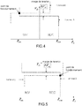
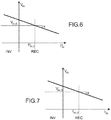
- the terms "INV” and “REC” used on the Figures 2 to 7 correspond respectively to an operation inverter (“Inverter”) and rectifier (“Rectifier”).
- This control uses a “droop” mechanism to regulate the DC voltage in adjusting the power injections of the converters ( figure 6 ) or current injections ( figure 7 ).
- This expression is used to calculate the power injection in each DC node, when the voltage values are previously known.
- the nodes are power controllers or voltage controllers, which means that in a node the known variable is either the DC voltage or the DC power injection.
- a system of non-linear equations must then be solved. This is the role of the power transit calculation.
- the purpose of the power transit calculation is to achieve a stable operating point of the network by solving a system of non-linear equations. This calculation makes it possible to analyze the power systems and can be used to find a starting point for a dynamic system analysis or to do a contingency analysis.
- the equations can be rewritten using a resolution method chosen for example the technique of Newton Raphson.
- the generalized method offers the possibility of integrating a "droop" DC voltage control.
- the generalized method allows to include converters under distributed voltage control. This method makes it possible to obtain DC voltages. The unknown power injections can then be calculated.
- X dc , mod j X dc , mod - X dc , mod , callus
- the power transit resolution flow chart using this generalized method with voltage / power control is shown on the figure 10 .
- the HVDC network is started after a power transit calculation based on the master / slave strategy to compute the initial conditions. Then a more generalized algorithm adapted to the chosen strategy (master / slave, voltage margin or droop) is launched to calculate the new points of operation of the multiterminal network.
- a secondary control controls the frequency of the system and cross-border power exchanges back to the original desired values after 15 to 30 seconds if the requested power demand does not reach the reserve saturation limit.
- the DC voltage is controlled and must be kept within an acceptable margin of + 10%.
- Primary control tends to return to the balance power output-power consumption.
- the purpose of the secondary control is to reduce the voltage variation due to the first control.
- the secondary control approach has the effect of a parallel shift of the "droop" characteristic, which means that an offset is added, keeping the corresponding droop constant (slope).
- the DC voltage is set to a value determined during the application of the control secondary. Depending on this value (considered equal to 1 pu) the DC voltage in this node must increase or decrease and with it the DC voltage in the other nodes. Considering, for example, the first moment when the secondary control is applied, the DC voltage in node 3 must increase from 0.9960 pu to 1 pu. Since the DC power in the nodes 1 and 2 is kept constant, increasing their voltages DC causes the decrease of their injected DC currents, which causes a reduction of the link losses. Thus, and since the master converter is responsible for achieving the power balance, the DC power injected into this node also decreases.
- the invention makes it possible to take into account the vulnerability of the new VSC-MTDC stable state after a disturbance following the application of the chosen "droop" primary control, a method using the master / slave DC voltage control strategy makes it possible to optimizing the values of the DC voltages without noticeable influence on the power distribution, by bringing the DC voltage of the converters back to a determined reference point.
Landscapes
- Engineering & Computer Science (AREA)
- Power Engineering (AREA)
- Direct Current Feeding And Distribution (AREA)
Description
L'invention concerne un procédé de contrôle d'un réseau multi-terminal VSC-HVDC.The invention relates to a method for controlling a VSC-HVDC multi-terminal network.
Le domaine de l'ingénierie de puissance est confronté à d'énormes défis, notamment du fait que les énergies intermittentes renouvelables, qui présentent un intérêt croissant, nécessitent un grand nombre de limitations techniques. En effet, l'utilisation de telles énergies doit pouvoir garantir un fonctionnement sûr, autonome, propre et compétitif, qui puisse être maintenu. La génération de puissance éolienne est une solution réaliste qui a incité différents pays à installer des fermes éoliennes offshore. En Europe, le potentiel éolien offshore est capable de couvrir 7 fois sa demande totale. Le réseau HVAC (très hautes tensions en courant alternatif) fournit un procédé simple et économique pour des courtes distances. Mais la distance des fermes offshore à la terre, qui dépasse 50 à 80 km, rend nécessaire une transmission en HVDC (haute tension courant continu) comme décrit dans les documents référencés [2] et [3] en fin de description. De plus, la circulation d'un courant continu (DC), au lieu d'un courant alternatif (AC), à travers les mêmes pylônes et lignes, permet de transmettre jusqu'à trois fois plus de puissance dans une même voie de passage. Les systèmes HVDC peuvent utiliser deux technologies différentes : les convertisseurs à source de courant classiques (CSC) HVDC et les convertisseurs à sources de tension (VSC) HVDC. Les spécificités de la technologie CSC ne permettent pas un fonctionnement multi-terminal dans le cas où plus de trois convertisseurs sont utilisés. La technologie VSC, comme décrit dans le document référencé [3], est nettement meilleure que la technologie CSC en termes de commande de puissance active et réactive, indépendante, rapide et flexible. Un changement de direction de transit de puissance dans un système CSC est complexe et nécessite une commutation mécanique. Par contre un convertisseur VSC, qui se comporte comme un générateur synchrone, permet de résoudre un tel problème de changement de direction de transit de puissance.The field of power engineering faces enormous challenges, especially as renewable intermittent energies, which are of increasing interest, require a large number of technical limitations. Indeed, the use of such energies must be able to guarantee a safe, autonomous, clean and competitive operation that can be maintained. Wind power generation is a realistic solution that has motivated different countries to set up offshore wind farms. In Europe, the offshore wind potential is able to cover 7 times its total demand. The HVAC network (Very High Voltage AC) provides a simple and economical process for short distances. But the distance of offshore farms to earth, which exceeds 50 to 80 km, makes it necessary to transmit in HVDC (high-voltage direct current) as described in documents referenced [2] and [3] at the end of the description. In addition, the circulation of a direct current (DC), instead of an alternating current (AC), through the same pylons and lines, allows to transmit up to three times more power in the same way of passage . The HVDC systems can use two different technologies: HVDC conventional power source converters (HVACs) and HVDC voltage source converters (VSCs). The specificities of the CSC technology do not allow multi-terminal operation in the case where more than three converters are used. The VSC technology, as described in the referenced document [3], is significantly better than the CSC technology in terms of active and reactive, independent, fast and flexible power control. A change in power flow direction in a CSC system is complex and requires mechanical switching. On the other hand, a VSC converter, which behaves like a synchronous generator, makes it possible to solve such a problem of change of direction of transit of power.
Le contrôle de tension DC est l'une des principales taches d'un convertisseur à source de tension VSC dans un réseau de transmission VSC-HVDC. La tension DC doit être contrôlée à l'intérieur de limites strictes afin de garantir un équilibre de puissance entre tous les terminaux de transmission du réseau multi-terminal VSC-HVDC. Dans un système de transmission HVDC point à point, l'un des terminaux contrôle la tension DC de la liaison de transmission tandis que l'autre terminal contrôle la puissance active envoyée à l'interconnexion. Ce type de contrôle correspond à une stratégie de contrôle « maître/esclave ». Mais, il n'est pas évident de faire fonctionner un réseau VSC-HVDC avec un seul terminal qui contrôle la tension DC principalement pour deux raisons : la puissance nominale du terminal VSC, qui contrôle la tension DC, est limitée et l'existence éventuelle de défauts dans le réseau AC connecté à ce terminal peut déclencher un équipement de protection en seulement quelques cycles du réseau AC. Une distribution de la responsabilité du contrôle de tension DC à plus d'un terminal VSC pour faire fonctionner un système VSC-HVDC serait donc avantageuse.DC voltage control is one of the main tasks of a VSC voltage source converter in a VSC-HVDC transmission network. The DC voltage must be controlled within strict limits to ensure a power balance between all transmission terminals of the VSC-HVDC multi-terminal network. In a point-to-point HVDC transmission system, one of the terminals controls the DC voltage of the transmission link while the other terminal controls the active power sent to the interconnection. This type of control corresponds to a "master / slave" control strategy. But, it is not easy to operate a VSC-HVDC network with a single terminal that controls the DC voltage mainly for two reasons: the nominal power of the VSC terminal, which controls the DC voltage, is limited and the possible existence of faults in the AC network connected to this terminal can trigger protection equipment in just a few cycles of the AC network. A distribution of DC voltage control responsibility to more than one VSC terminal to operate a VSC-HVDC system would therefore be advantageous.
Les documents référencés [1] à [5] en fin de description décrivent différents systèmes de l'art connu dans le domaine de l'invention. Le document [1] décrit le contrôle d'un convertisseur autonome dans un système HVDC multi-terminal. Le développement et la disponibilité croissante de multiples vendeurs de la technologie convertisseur à source de tension (VSC), l'étude de réseaux multi-terminal HVDC qui sont des réseaux HVDC composés de plusieurs convertisseurs est devenue réalité. Dans de tels réseaux, la puissance qui entre ou sort de chaque convertisseur peut être changée dynamiquement sans reconfiguration du réseau HVDC. Le document [2] décrit la gestion du réseau DC d'un système de transmission multi-terminal HVDC pour de grandes fermes éoliennes offshore. Le document [3] décrit la connexion VSC multi-terminal HVDC de fermes éoliennes offshore. Le document [4] décrit des systèmes multi-terminal VSC-HVDC avec un contrôle de tension DC distribuée avec une approche à flux de puissance. Le document [5] décrit un procédé de contrôle de tension DC distribuée pour des systèmes multi-terminal VSC-HVDC.The documents referenced [1] to [5] at the end of the description describe various systems of the prior art in the field of the invention. Document [1] describes the control of an autonomous converter in a multi-terminal HVDC system. The development and increasing availability of multiple vendors of voltage source converter (VSC) technology, the study of multi-terminal HVDC networks that are HVDC networks composed of multiple converters has become reality. In such networks, the power that enters or leaves each converter can be changed dynamically without reconfiguring the HVDC network. Document [2] describes the management of the DC network of a HVDC multi-terminal transmission system for large offshore wind farms. Document [3] describes the VSC multi-terminal HVDC connection of offshore wind farms. Document [4] describes VSC-HVDC multi-terminal systems with DC voltage control distributed with a power flow approach. Document [5] describes a distributed DC voltage control method for VSC-HVDC multi-terminal systems.
Le document "
L'objet de l'invention est de proposer un procédé de contrôle primaire et secondaire d'un réseau multi-terminal VSC-HVDC qui puisse être aisément intégré par des opérateurs de transmission et de distribution.The object of the invention is to propose a method of primary and secondary control of a VSC-HVDC multi-terminal network which can be easily integrated by transmission and distribution operators.
L'invention concerne un procédé de contrôle d'un réseau multi-terminal VSC-HVDC comprenant une stratégie de contrôle primaire tendant à revenir à un équilibre production de puissance-consommation de puissance et une stratégie de contrôle secondaire pour réduire toute variation de tension due à la première stratégie, caractérisé en ce qu'il comporte les étapes suivantes :
- dans une période de temps t comprise entre 0 et T, on réalise un calcul de transit de puissance en fonctionnement normal, avec un noeud pris comme convertisseur maître,
- au temps t=T, on produit une perturbation en un premier noeud autre que le noeud précédent,
- dans la période de temps t comprise entre T et 2T, un contrôle de tension « droop » est actif et la perte de puissance est répartie sur les autres noeuds,
- au temps t=2T, on applique un contrôle secondaire suivant une stratégie maître/esclave, en fixant la tension à sa valeur avant la perturbation,
- au temps t=3T, l'injection de puissance au premier noeud revient à sa valeur initiale, c'est-à-dire avant la perturbation, et le contrôle de tension « droop » est réactivé,
- au temps t=4T, on active un contrôle secondaire pour réduire la variation des tensions DC en appliquant une stratégie de contrôle de tension DC maître/esclave.
- in a period of time t between 0 and T, a power transit calculation is carried out during normal operation, with a node taken as a master converter,
- at time t = T, a disturbance is produced at a first node other than the preceding node,
- in the time period t between T and 2T, a "droop" voltage control is active and the power loss is distributed over the other nodes,
- at time t = 2T, a secondary control is applied according to a master / slave strategy, setting the voltage to its value before the disturbance,
- at time t = 3T, the injection of power at the first node returns to its initial value, that is to say before the disturbance, and the voltage control "droop" is reactivated,
- at time t = 4T, a secondary control is activated to reduce the variation of DC voltages by applying a master / slave DC voltage control strategy.
Avantageusement lors de la stratégie primaire on applique une stratégie de contrôle de tension DC de type « droop », et lors de la stratégie secondaire on applique une stratégie de contrôle de tension DC selon la topologie et la puissance des noeuds interconnectés, par exemple une stratégie de type maître/esclave ou une stratégie par marge de tension.Advantageously, during the primary strategy, a DC voltage control strategy of the "droop" type is applied, and during the secondary strategy a DC voltage control strategy is applied according to the topology and the power of the interconnected nodes, for example a strategy master / slave type or strategy by voltage margin.
Avantageusement T est adapté aux réponses des systèmes interconnectés sur le réseau, par exemple T=50 secondes.Advantageously T is adapted to the responses of the interconnected systems on the network, for example T = 50 seconds.
Il faut noter, en effet, que les dernières avancées technologiques permettent d'envisager l'utilisation de la technologie VSC-HVDC dans une gamme de puissance supérieure. L'utilisation d'un système multi-terminal VSC-HVDC est donc envisageable. Le procédé de contrôle d'un tel réseau VSC-HVDC selon l'invention permet alors d'interconnecter des fermes éoliennes offshore situées à distance à plusieurs points à l'infrastructure AC existante, pour fournir un réseau plus sûr. Un tel réseau VSC-HVDC présente de nombreux avantages économiques et techniques par rapport à un réseau HVAC.It should be noted, in fact, that the latest technological advances make it possible to consider the use of VSC-HVDC technology in a higher power range. The use of a VSC-HVDC multi-terminal system is therefore possible. The method of controlling such a VSC-HVDC network according to the invention then makes it possible to interconnect remote offshore wind farms at several points to the existing AC infrastructure, to provide a more secure network. Such a VSC-HVDC network has many economic and technical advantages over an HVAC network.
-
La
figure 1 illustre un réseau HVDC à trois terminaux.Thefigure 1 illustrates a three-terminal HVDC network. -
Les
figures 2 et 3 illustrent un contrôle de tension de type « maître/esclave ».TheFigures 2 and 3 illustrate a "master / slave" type voltage control. -
Les
figures 4 et 5 illustrent un contrôle de tension de type par « marge de tension ».TheFigures 4 and 5 illustrate a type voltage control by "voltage margin". -
Les
figures 6 et 7 illustrent un contrôle de tension de type « droop ».TheFigures 6 and 7 illustrate a "droop" type voltage control. -
La
figure 8 illustre la modélisation d'un réseau HVDC.Thefigure 8 illustrates the modeling of an HVDC network. -
La
figure 9 illustre une méthode généralisée de calcul de transit de puissance DC.Thefigure 9 illustrates a generalized method of calculating DC power transit. -
La
figure 10 illustre un organigramme de résolution de la méthode illustrée sur lafigure 9 .Thefigure 10 illustrates a flowchart of resolution of the method illustrated on thefigure 9 . -
La
figure 11 illustre la mise en oeuvre de la méthode illustrée sur lafigure 9 .Thefigure 11 illustrates the implementation of the illustrated method on thefigure 9 . -
Les
figures 12A et 12B et13A et 13B illustrent le fonctionnement du procédé de l'invention.TheFigures 12A and 12B and13A and 13B illustrate the operation of the method of the invention.
Un réseau HVDC comprenant ici trois terminaux, tel que représenté sur la
- La tension DC dans un tel réseau HVDC est équivalente à la fréquence dans un réseau HVAC en termes d'équilibre dans le réseau. Elle change lorsque la production est différente de la consommation.
- Le transit de puissance (active) est dicté par des amplitudes de tensions entre les différents noeuds.
- la matrice d'admittance contient seulement les résistances des câbles, car on ne prend en considération que le régime permanent.
- En un noeud, on peut contrôler soit l'injection de puissance soit la tension DC.
- The DC voltage in such an HVDC network is equivalent to the frequency in an HVAC network in terms of balance in the network. It changes when production is different from consumption.
- Power (active) transit is dictated by amplitudes of voltages between the different nodes.
- the admittance matrix contains only the resistances of the cables, since only the steady state is taken into consideration.
- In one node, it is possible to control either the power injection or the DC voltage.
Les différentes stratégies de contrôle de la tension DC dans un réseau HVDC vont, à présent, être passées en revue.The different DC voltage control strategies in an HVDC network will now be reviewed.
Dans cette stratégie illustrée sur les
Dans cette stratégie illustrée sur les
Dans cette stratégie décrite dans les documents référencés [3] et [5], le contrôle de tension DC est réparti sur plusieurs convertisseurs, qui adaptent simultanément leurs injections de puissance active pour tenir compte de situations perturbées du réseau. Le contrôle de la tension DC est réparti en suivant l'une des caractéristiques illustrées sur les ![]()
![]()
![]()
![]()
![]()
![]()
Chaque convertisseur contribue au contrôle à la mesure de ses moyens. La modélisation d'un réseau HVDC, avec un convertisseur VSC 10 est illustrée sur la ![]()
![]()

et la matrice admittance DC : 


![]()
![]()
and the admittance matrix DC:
La puissance active dans chaque noeud est telle que : ![]()

![]()
Cette expression est utilisée pour calculer l'injection de puissance dans chaque noeud DC, lorsque les valeurs de tension sont préalablement connues. En effet, dans un réseau DC les noeuds sont des contrôleurs de puissance ou des contrôleurs de tension, ce qui signifie que dans un noeud la variable connue est soit la tension DC soit l'injection de puissance DC. Un système d'équations non linéaires doit alors être résolu. C'est le rôle du calcul de transit de puissance.This expression is used to calculate the power injection in each DC node, when the voltage values are previously known. Indeed, in a DC network, the nodes are power controllers or voltage controllers, which means that in a node the known variable is either the DC voltage or the DC power injection. A system of non-linear equations must then be solved. This is the role of the power transit calculation.
Le calcul de transit de puissance a pour objet de permettre d'atteindre un point de fonctionnement stable du réseau, en résolvant un système d'équations non linéaires. Ce calcul permet d'analyser les systèmes de puissance et peut être utilisé pour trouver un point de départ pour une analyse de système dynamique ou pour faire une analyse de contingence. En partant du modèle mathématique du réseau DC, les équations peuvent être réécrites en utilisant une méthode de résolution choisie par exemple la technique de Newton Raphson. La méthode généralisée offre la possibilité d'intégrer un contrôle de tension DC « droop ».The purpose of the power transit calculation is to achieve a stable operating point of the network by solving a system of non-linear equations. This calculation makes it possible to analyze the power systems and can be used to find a starting point for a dynamic system analysis or to do a contingency analysis. Starting from the mathematical model of the DC network, the equations can be rewritten using a resolution method chosen for example the technique of Newton Raphson. The generalized method offers the possibility of integrating a "droop" DC voltage control.
La méthode généralisée permet d'inclure des convertisseurs sous contrôle de tension distribué. Cette méthode permet d'obtenir les tensions DC. Les injections de puissance non connues peuvent alors être calculées.The generalized method allows to include converters under distributed voltage control. This method makes it possible to obtain DC voltages. The unknown power injections can then be calculated.
Comme illustré sur la
- la tension DC dans le convertisseur maître Vdc,n
- l'injection de puissance DC Pdc dans les noeuds de commande de puissance
- la matrice d'admittance ydc
- les contrôleurs « droop » V dc,0, Pdc,o /Idc,o , les sorties sont les tensions Vdc .
- the DC voltage in the master converter V dc , n
- DC power Pdc injection into the power control nodes
- admittance matrix y dc
- the controllers "droop" V dc, 0 , P dc, o / I dc, o , the outputs are the voltages V dc .
Pour la résolution des équations non linéaires, on utilise le Jacobien (dérivée multidimensionnelle) qui a la forme suivants : 
![]()
![]()
![]()
![]()
![]()
![]()
![]()
![]()
L'organigramme de résolution de transit de puissance utilisant cette méthode généralisée avec contrôle tension/puissance est illustré sur la
Le réseau HVDC est lancé après un calcul de transit de puissance basé sur la stratégie maître/esclave pour calculer les conditions initiales. Ensuite un algorithme plus généralisé adapté à la stratégie choisie (maître/esclave, marge de tension ou droop) est lancé pour calculer les nouveaux points de fonctionnement du réseau multiterminal.The HVDC network is started after a power transit calculation based on the master / slave strategy to compute the initial conditions. Then a more generalized algorithm adapted to the chosen strategy (master / slave, voltage margin or droop) is launched to calculate the new points of operation of the multiterminal network.
La mise en oeuvre de cette méthode est illustrée sur la
On va, à présent, considérer la stratégie de contrôle secondaire du procédé de l'invention.We will now consider the secondary control strategy of the method of the invention.
Dans tout système électrique la génération et la consommation de puissance active doivent se compenser pour éviter toute coupure de courant. Les unités de génération de puissance, et même les charges dans certains cas, doivent être contrôlées pour maintenir un équilibre de puissance de telle sorte que les utilisateurs du réseau ne soient pas affectés par des changements de charge ou par des pannes de génération et de transmission de puissance.In any electrical system the generation and the active power consumption must be compensated to avoid any power failure. Power generation units, and even loads in some cases, must be controlled to maintain a power balance so that network users are not affected by load changes or generation and transmission failures. power.
Dans un réseau multi-terminal AC, un contrôle secondaire pilote la fréquence du système et les échanges de puissance transfrontière de retour vers les valeurs souhaitées originales après 15 à 30 secondes si la puissance requise activée n'atteint pas la limite de saturation de la réserve.In a multi-terminal AC network, a secondary control controls the frequency of the system and cross-border power exchanges back to the original desired values after 15 to 30 seconds if the requested power demand does not reach the reserve saturation limit. .
Dans un réseau multi-terminal VDC-HVDC la tension DC est contrôlée et doit être maintenue dans une marge acceptable de + 10%. Le contrôle primaire tend à revenir à l'équilibre production de puissance-consommation de puissance. Le contrôle secondaire a pour objet de réduire la variation de tension due au premier contrôle.In a VDC-HVDC multi-terminal network the DC voltage is controlled and must be kept within an acceptable margin of + 10%. Primary control tends to return to the balance power output-power consumption. The purpose of the secondary control is to reduce the voltage variation due to the first control.
Une telle approche de contrôle secondaire selon l'invention est à présent appliquée à un réseau HVDC à trois terminaux (système maillé le plus simple). Les
- dans une période de temps t comprise
entre 0 et T, T étant adapté aux réponses des systèmes interconnectés sur le réseau par exemple égal à 50 secondes, on réalise un calcul de transit de puissance en fonctionnement normal, c'est-à-dire avant toute perturbation : avec un noeud (ici le noeud 3) comme convertisseur maître (bus référence ou « slack bus »), - au temps t=T, on produit une perturbation en un premier noeud (ici le noeud 1) autre que noeud précédent sous la forme d'un échelon de puissance, où l'injection de puissance tombe à zéro,
- dans la période de temps t comprise entre T et 2T, le contrôle « droop » de tension est actif et la perte de puissance est répartie sur les autres noeuds (ici les noeuds 2 et 3), formant ainsi un contrôle primaire, une génération de puissance étant perdue, ce qui à pour conséquence une diminution de la tension DC dans tous les noeuds,
- au temps t=2T, on applique un contrôle secondaire et les variations de tension sont réduites, ce contrôle secondaire suivant une stratégie maître/esclave, en fixant la tension à sa valeur avant la perturbation. Les valeurs de puissance dans tous les noeuds ayant subi une légère variation comme illustré sur la
figure 12A , - au temps t=3T, l'injection de puissance au premier noeud revient à sa valeur initiale, c'est-à-dire avant la perturbation, et le contrôle de tension « droop » est réactivé, les injections de puissance dans les deux autres noeuds (noeuds 2 et 3) revenant également à leurs valeurs initiales, avec une augmentation des tensions DC,
- au temps t=4T, un contrôle secondaire est activé pour réduire la variation des tensions DC en appliquant une fois de plus une stratégie de contrôle de tension DC maître/esclave de telle façon que les tensions DC retrouvent leurs valeurs initiales avec une variation imperceptible de l'injection de puissance du convertisseur maître.
- in a period of time t between 0 and T, T being adapted to the responses of the interconnected systems on the network, for example equal to 50 seconds, a power transit calculation is carried out in normal operation, that is to say before any disturbance: with a node (here node 3) as master converter (reference bus or "slack bus"),
- at time t = T, a disturbance is produced at a first node (here node 1) other than the preceding node in the form of a power step, where the power injection drops to zero,
- in the time period t between T and 2T, the voltage droop control is active and the loss of power is distributed over the other nodes (here the
nodes 2 and 3), thus forming a primary control, a generation of power being lost, which results in a decrease of the DC voltage in all the nodes, - at time t = 2T, a secondary control is applied and the voltage variations are reduced, this secondary control following a master / slave strategy, setting the voltage to its value before the disturbance. The power values in all the nodes having undergone a slight variation as illustrated on the
figure 12A , - at time t = 3T, the injection of power at the first node returns to its initial value, that is to say before the disturbance, and the voltage control "droop" is reactivated, the power injections in the other two nodes (
nodes 2 and 3) returning also at their initial values, with an increase in DC voltages, - at time t = 4T, a secondary control is activated to reduce the variation of DC voltages by once again applying a master / slave DC voltage control strategy in such a way that the DC voltages recover their initial values with an imperceptible variation of the power injection of the master converter.
Une évolution détaillée de la puissance DC et de la tension DC des trois noeuds est représentée dans le tableau ci-dessous.
Une évolution détaillée de la puissance DC et de la tension DC sur le diagramme « droop » des noeuds, qui sont sous le contrôle de tension DC « droop » (noeuds 2 et 3) est représentée sur les
Comme illustré sur les
L'invention permet de tenir compte de la vulnérabilité du nouvel état stable VSC-MTDC après une perturbation à la suite de l'application du contrôle primaire « droop » choisi, une méthode utilisant la stratégie de contrôle de tension DC maître/esclave permet d'optimiser les valeurs des tensions DC sans influence perceptible sur la distribution de puissance, en ramenant la tension DC des convertisseurs à un point de référence déterminé.The invention makes it possible to take into account the vulnerability of the new VSC-MTDC stable state after a disturbance following the application of the chosen "droop" primary control, a method using the master / slave DC voltage control strategy makes it possible to optimizing the values of the DC voltages without noticeable influence on the power distribution, by bringing the DC voltage of the converters back to a determined reference point.
-
[1]
C. Barker et R. Whitehouse, "Autonomous converter control in a multiterminal HVDC system" (Proc. IET ACDC'10, Londres, Royaume-Uni, 20-21 Octobre, 2010 C. Barker and R. Whitehouse, "Autonomous converter control in a multiterminal HVDC system" (Proc IET ACDC'10, London, United Kingdom, October 20-21, 2010 -
[2]
L. Xu, L. Yao, et M. Bazargan, "DC Grid Management of a Multi-Terminal HVDC Transmission System for Large Offshore Wind Farms". (International Conférence on Sustainable Power Generation and Supply, SUPERGEN'09, pages 1-7, 2009 L. Xu, L. Yao, and M. Bazargan, "DC Grid Management of a Multi-Terminal HVDC Transmission System for Large Offshore Wind Farms". (International Conference on Sustainable Power Generation and Supply, SUPERGEN'09, pages 1-7, 2009 -
[3]
S. Wandenbrencke, "multi-terminal VSC HVDC connection of offshore wind farms" (2010-2011, pages 1 à 108, Université de Louvain S. Wandenbrencke, "VSC multi-terminal HVDC connection of offshore wind farms" (2010-2011, pages 1 to 108, University of Leuven -
[4]
J. Beerfen, D. Van Hertem, et R. Belmans, "VSC MTDC systems with a distributed DC voltage control - A power flow approach," (Proc. IEEE PowerTech'11, Trondheim, Norvège, 19-23 Juin 2011, pages 1-6 J. Beerfen, D. Van Hertem, and R. Belmans, "VSC MTDC Systems with DC Voltage Controlled - A Power Flow Approach," (IEEE PowerTech'11 Processes, Trondheim, Norway, 19-23 June 2011, pp. 1-6 -
[5]
C. Dierckxsens, K. Srivastava, M. Reza, S. Cole, J. Beerten, R. Belmans, « A distributed DV voltage control method for VSC MTDC systems (Electric Power Systems Research, Elsevier, 2011, pages 54-58 C. Dierckxsens, K. Srivastava, M. Reza, S. Cole, J. Beerten, R. Belmans, "Distributed DV Voltage Control Method for VSC MTDC Systems" (Electric Power Systems Research, Elsevier, 2011, pages 54-58).
Claims (5)
- A method of controlling a multi-terminal HVDC network, the method comprising a primary control strategy tending to restore balance between power production and power consumption and a secondary control strategy for reducing any variation in voltage resulting from the first strategy, characterized in that it includes the following steps:• in a period of time t lying in the range 0 to T, calculating power flow in normal operation, with a node that is taken as a master converter;• at time t=T, producing a disturbance in a first node that is not the above-mentioned node;• in the period of time t lying in the range T to 2T, voltage droop control is active and the loss of power is distributed over the other nodes;• at time t=2T, applying a secondary control using a master/slave strategy, by fixing the voltage at its value before the disturbance;• at time t=3T, the injection of power to the first node returns to its initial value, i.e. before the disturbance, and voltage droop control is reactivated; and• at time t=4T, secondary control is activated in order to reduce the DC voltage variation by applying a master/slave DC voltage control strategy.
- The method according to claim 1, wherein during the primary strategy, a droop type DC voltage control strategy is applied.
- The method according to either preceding claim, wherein during the secondary strategy a DC voltage control strategy is applied that depends on the topology and the power of the interconnected nodes.
- A method according to claim 3, wherein the DC voltage control strategy is a master/slave strategy or a voltage margin strategy.
- A method according to claim 1, wherein T is adapted to the response times of the systems interconnected on the network.
Applications Claiming Priority (2)
| Application Number | Priority Date | Filing Date | Title |
|---|---|---|---|
| FR1260534A FR2997804B1 (en) | 2012-11-06 | 2012-11-06 | METHOD FOR CONTROLLING A VSC-HVDC MULTI-TERMINAL NETWORK |
| PCT/EP2013/072917 WO2014072246A1 (en) | 2012-11-06 | 2013-11-04 | Method for controlling a multi-terminal vsc-hvdc network |
Publications (2)
| Publication Number | Publication Date |
|---|---|
| EP2917992A1 EP2917992A1 (en) | 2015-09-16 |
| EP2917992B1 true EP2917992B1 (en) | 2017-01-04 |
Family
ID=47624342
Family Applications (1)
| Application Number | Title | Priority Date | Filing Date |
|---|---|---|---|
| EP13789748.4A Active EP2917992B1 (en) | 2012-11-06 | 2013-11-04 | Method for controlling a multi-terminal vsc-hvdc |
Country Status (3)
| Country | Link |
|---|---|
| EP (1) | EP2917992B1 (en) |
| FR (1) | FR2997804B1 (en) |
| WO (1) | WO2014072246A1 (en) |
Families Citing this family (6)
| Publication number | Priority date | Publication date | Assignee | Title |
|---|---|---|---|---|
| US10008854B2 (en) | 2015-02-19 | 2018-06-26 | Enphase Energy, Inc. | Method and apparatus for time-domain droop control with integrated phasor current control |
| WO2017077045A1 (en) * | 2015-11-06 | 2017-05-11 | Danmarks Tekniske Universitet | Method to predetermine current/power flow change in a dc grid |
| ES2711005B2 (en) * | 2017-10-25 | 2024-03-07 | Univ Madrid Carlos Iii | Method for distributed frequency control in an offshore wind farm |
| CN108879650B (en) * | 2018-06-27 | 2021-09-03 | 广东电网有限责任公司电力科学研究院 | Coordination optimization control method and device for multi-terminal flexible direct-current power transmission system |
| CN110544954B (en) * | 2019-09-27 | 2021-09-03 | 南方电网科学研究院有限责任公司 | Multi-terminal direct current transmission system and transmission path selection method |
| CN111509760A (en) * | 2020-05-15 | 2020-08-07 | 南方电网科学研究院有限责任公司 | VSC virtual synchronization method and system for inter-regional power grid interconnection |
-
2012
- 2012-11-06 FR FR1260534A patent/FR2997804B1/en active Active
-
2013
- 2013-11-04 WO PCT/EP2013/072917 patent/WO2014072246A1/en active Application Filing
- 2013-11-04 EP EP13789748.4A patent/EP2917992B1/en active Active
Also Published As
| Publication number | Publication date |
|---|---|
| FR2997804A1 (en) | 2014-05-09 |
| EP2917992A1 (en) | 2015-09-16 |
| WO2014072246A1 (en) | 2014-05-15 |
| FR2997804B1 (en) | 2016-02-12 |
Similar Documents
| Publication | Publication Date | Title |
|---|---|---|
| EP2917992B1 (en) | Method for controlling a multi-terminal vsc-hvdc | |
| Augustine et al. | Control of photovoltaic‐based low‐voltage dc microgrid system for power sharing with modified droop algorithm | |
| US11527955B2 (en) | Systems, methods and devices for control of DC/DC converters and a standalone DC microgrid using artificial neural networks | |
| Beniwal et al. | Control and operation of a solar PV‐battery‐grid‐tied system in fixed and variable power mode | |
| EP2756577B1 (en) | Stabilization of an electrical dc grid | |
| Aly et al. | Assessment of reactive power contribution of photovoltaic energy systems on voltage profile and stability of distribution systems | |
| Jibji‐Bukar et al. | Frequency support from photovoltaic power plants using offline maximum power point tracking and variable droop control | |
| US11631978B2 (en) | Real-time estimation of contributions from classes of energy generators in residual load signals | |
| EP3818606A1 (en) | Device for active electrical compensation | |
| US20210397762A1 (en) | Distribution grid admittance estimation with limited nonsynchronized measurements | |
| EP3598598B1 (en) | Method and system for determining a voltage state of a low voltage power supply network located at at least one transformer station | |
| WO2019008275A1 (en) | Converter provided with a module for managing partly alternating power | |
| WO2019097183A1 (en) | Device for controlling a terminal for the compensation of a voltage disturbance | |
| EP3044865B1 (en) | Command system for an electric charge | |
| Mortezapour et al. | Adaptive primary droop control for islanded operation of hybrid AC–DC MGs | |
| Yue et al. | Assessing cloud transient impacts of solar and battery energy systems on grid inertial responses | |
| EP3454142B1 (en) | Method for monitoring and controlling an electrical power network | |
| Das et al. | A probabilistic approach to assess the adequacy of wind and solar energy | |
| WO2010079276A1 (en) | Method and system for transmitting electric energy | |
| FR3028080A1 (en) | METHOD OF MANAGING THE REAL-TIME ELECTRIC POWER DISTRIBUTION OVER AN ILOTE NETWORK | |
| EP3510686A1 (en) | Analogue overall balancing system for an assembly of capacitive-effect electrical energy storage devices, rechargeable storage module, electric vehicle and electrical installation comprising such a system | |
| EP2582002A2 (en) | Method for controlling the voltage in a grid comprising decentralised sources | |
| EP2533391B1 (en) | Multi-source management system of electrical generators | |
| Choi et al. | Advanced active power control considering the characteristics of distributed energy resources in microgrid | |
| Nazari et al. | On-line control of multi-terminal hvdc systems connected to offshore wind farms using the opf-based multi-agent approarch |
Legal Events
| Date | Code | Title | Description |
|---|---|---|---|
| PUAI | Public reference made under article 153(3) epc to a published international application that has entered the european phase |
Free format text: ORIGINAL CODE: 0009012 |
|
| 17P | Request for examination filed |
Effective date: 20150511 |
|
| AK | Designated contracting states |
Kind code of ref document: A1 Designated state(s): AL AT BE BG CH CY CZ DE DK EE ES FI FR GB GR HR HU IE IS IT LI LT LU LV MC MK MT NL NO PL PT RO RS SE SI SK SM TR |
|
| AX | Request for extension of the european patent |
Extension state: BA ME |
|
| DAX | Request for extension of the european patent (deleted) | ||
| RAP1 | Party data changed (applicant data changed or rights of an application transferred) |
Owner name: GENERAL ELECTRIC TECHNOLOGY GMBH |
|
| GRAP | Despatch of communication of intention to grant a patent |
Free format text: ORIGINAL CODE: EPIDOSNIGR1 |
|
| GRAJ | Information related to disapproval of communication of intention to grant by the applicant or resumption of examination proceedings by the epo deleted |
Free format text: ORIGINAL CODE: EPIDOSDIGR1 |
|
| GRAP | Despatch of communication of intention to grant a patent |
Free format text: ORIGINAL CODE: EPIDOSNIGR1 |
|
| INTG | Intention to grant announced |
Effective date: 20160622 |
|
| INTG | Intention to grant announced |
Effective date: 20160718 |
|
| GRAS | Grant fee paid |
Free format text: ORIGINAL CODE: EPIDOSNIGR3 |
|
| STAA | Information on the status of an ep patent application or granted ep patent |
Free format text: STATUS: GRANT OF PATENT IS INTENDED |
|
| GRAA | (expected) grant |
Free format text: ORIGINAL CODE: 0009210 |
|
| STAA | Information on the status of an ep patent application or granted ep patent |
Free format text: STATUS: THE PATENT HAS BEEN GRANTED |
|
| AK | Designated contracting states |
Kind code of ref document: B1 Designated state(s): AL AT BE BG CH CY CZ DE DK EE ES FI FR GB GR HR HU IE IS IT LI LT LU LV MC MK MT NL NO PL PT RO RS SE SI SK SM TR |
|
| REG | Reference to a national code |
Ref country code: GB Ref legal event code: FG4D Free format text: NOT ENGLISH |
|
| REG | Reference to a national code |
Ref country code: CH Ref legal event code: EP |
|
| REG | Reference to a national code |
Ref country code: AT Ref legal event code: REF Ref document number: 860112 Country of ref document: AT Kind code of ref document: T Effective date: 20170115 |
|
| REG | Reference to a national code |
Ref country code: IE Ref legal event code: FG4D Free format text: LANGUAGE OF EP DOCUMENT: FRENCH |
|
| REG | Reference to a national code |
Ref country code: DE Ref legal event code: R096 Ref document number: 602013016254 Country of ref document: DE |
|
| REG | Reference to a national code |
Ref country code: SE Ref legal event code: TRGR |
|
| REG | Reference to a national code |
Ref country code: LT Ref legal event code: MG4D Ref country code: NL Ref legal event code: MP Effective date: 20170104 |
|
| REG | Reference to a national code |
Ref country code: AT Ref legal event code: MK05 Ref document number: 860112 Country of ref document: AT Kind code of ref document: T Effective date: 20170104 |
|
| PG25 | Lapsed in a contracting state [announced via postgrant information from national office to epo] |
Ref country code: NL Free format text: LAPSE BECAUSE OF FAILURE TO SUBMIT A TRANSLATION OF THE DESCRIPTION OR TO PAY THE FEE WITHIN THE PRESCRIBED TIME-LIMIT Effective date: 20170104 |
|
| PG25 | Lapsed in a contracting state [announced via postgrant information from national office to epo] |
Ref country code: IS Free format text: LAPSE BECAUSE OF FAILURE TO SUBMIT A TRANSLATION OF THE DESCRIPTION OR TO PAY THE FEE WITHIN THE PRESCRIBED TIME-LIMIT Effective date: 20170504 Ref country code: FI Free format text: LAPSE BECAUSE OF FAILURE TO SUBMIT A TRANSLATION OF THE DESCRIPTION OR TO PAY THE FEE WITHIN THE PRESCRIBED TIME-LIMIT Effective date: 20170104 Ref country code: GR Free format text: LAPSE BECAUSE OF FAILURE TO SUBMIT A TRANSLATION OF THE DESCRIPTION OR TO PAY THE FEE WITHIN THE PRESCRIBED TIME-LIMIT Effective date: 20170405 Ref country code: NO Free format text: LAPSE BECAUSE OF FAILURE TO SUBMIT A TRANSLATION OF THE DESCRIPTION OR TO PAY THE FEE WITHIN THE PRESCRIBED TIME-LIMIT Effective date: 20170404 Ref country code: HR Free format text: LAPSE BECAUSE OF FAILURE TO SUBMIT A TRANSLATION OF THE DESCRIPTION OR TO PAY THE FEE WITHIN THE PRESCRIBED TIME-LIMIT Effective date: 20170104 Ref country code: LT Free format text: LAPSE BECAUSE OF FAILURE TO SUBMIT A TRANSLATION OF THE DESCRIPTION OR TO PAY THE FEE WITHIN THE PRESCRIBED TIME-LIMIT Effective date: 20170104 |
|
| PG25 | Lapsed in a contracting state [announced via postgrant information from national office to epo] |
Ref country code: BG Free format text: LAPSE BECAUSE OF FAILURE TO SUBMIT A TRANSLATION OF THE DESCRIPTION OR TO PAY THE FEE WITHIN THE PRESCRIBED TIME-LIMIT Effective date: 20170404 Ref country code: AT Free format text: LAPSE BECAUSE OF FAILURE TO SUBMIT A TRANSLATION OF THE DESCRIPTION OR TO PAY THE FEE WITHIN THE PRESCRIBED TIME-LIMIT Effective date: 20170104 Ref country code: PT Free format text: LAPSE BECAUSE OF FAILURE TO SUBMIT A TRANSLATION OF THE DESCRIPTION OR TO PAY THE FEE WITHIN THE PRESCRIBED TIME-LIMIT Effective date: 20170504 Ref country code: LV Free format text: LAPSE BECAUSE OF FAILURE TO SUBMIT A TRANSLATION OF THE DESCRIPTION OR TO PAY THE FEE WITHIN THE PRESCRIBED TIME-LIMIT Effective date: 20170104 Ref country code: ES Free format text: LAPSE BECAUSE OF FAILURE TO SUBMIT A TRANSLATION OF THE DESCRIPTION OR TO PAY THE FEE WITHIN THE PRESCRIBED TIME-LIMIT Effective date: 20170104 Ref country code: PL Free format text: LAPSE BECAUSE OF FAILURE TO SUBMIT A TRANSLATION OF THE DESCRIPTION OR TO PAY THE FEE WITHIN THE PRESCRIBED TIME-LIMIT Effective date: 20170104 Ref country code: RS Free format text: LAPSE BECAUSE OF FAILURE TO SUBMIT A TRANSLATION OF THE DESCRIPTION OR TO PAY THE FEE WITHIN THE PRESCRIBED TIME-LIMIT Effective date: 20170104 |
|
| REG | Reference to a national code |
Ref country code: DE Ref legal event code: R097 Ref document number: 602013016254 Country of ref document: DE |
|
| PG25 | Lapsed in a contracting state [announced via postgrant information from national office to epo] |
Ref country code: IT Free format text: LAPSE BECAUSE OF FAILURE TO SUBMIT A TRANSLATION OF THE DESCRIPTION OR TO PAY THE FEE WITHIN THE PRESCRIBED TIME-LIMIT Effective date: 20170104 Ref country code: CZ Free format text: LAPSE BECAUSE OF FAILURE TO SUBMIT A TRANSLATION OF THE DESCRIPTION OR TO PAY THE FEE WITHIN THE PRESCRIBED TIME-LIMIT Effective date: 20170104 Ref country code: SK Free format text: LAPSE BECAUSE OF FAILURE TO SUBMIT A TRANSLATION OF THE DESCRIPTION OR TO PAY THE FEE WITHIN THE PRESCRIBED TIME-LIMIT Effective date: 20170104 Ref country code: RO Free format text: LAPSE BECAUSE OF FAILURE TO SUBMIT A TRANSLATION OF THE DESCRIPTION OR TO PAY THE FEE WITHIN THE PRESCRIBED TIME-LIMIT Effective date: 20170104 Ref country code: EE Free format text: LAPSE BECAUSE OF FAILURE TO SUBMIT A TRANSLATION OF THE DESCRIPTION OR TO PAY THE FEE WITHIN THE PRESCRIBED TIME-LIMIT Effective date: 20170104 |
|
| PLBE | No opposition filed within time limit |
Free format text: ORIGINAL CODE: 0009261 |
|
| STAA | Information on the status of an ep patent application or granted ep patent |
Free format text: STATUS: NO OPPOSITION FILED WITHIN TIME LIMIT |
|
| REG | Reference to a national code |
Ref country code: FR Ref legal event code: PLFP Year of fee payment: 5 |
|
| PG25 | Lapsed in a contracting state [announced via postgrant information from national office to epo] |
Ref country code: DK Free format text: LAPSE BECAUSE OF FAILURE TO SUBMIT A TRANSLATION OF THE DESCRIPTION OR TO PAY THE FEE WITHIN THE PRESCRIBED TIME-LIMIT Effective date: 20170104 Ref country code: SM Free format text: LAPSE BECAUSE OF FAILURE TO SUBMIT A TRANSLATION OF THE DESCRIPTION OR TO PAY THE FEE WITHIN THE PRESCRIBED TIME-LIMIT Effective date: 20170104 |
|
| 26N | No opposition filed |
Effective date: 20171005 |
|
| PG25 | Lapsed in a contracting state [announced via postgrant information from national office to epo] |
Ref country code: SI Free format text: LAPSE BECAUSE OF FAILURE TO SUBMIT A TRANSLATION OF THE DESCRIPTION OR TO PAY THE FEE WITHIN THE PRESCRIBED TIME-LIMIT Effective date: 20170104 |
|
| PG25 | Lapsed in a contracting state [announced via postgrant information from national office to epo] |
Ref country code: MC Free format text: LAPSE BECAUSE OF FAILURE TO SUBMIT A TRANSLATION OF THE DESCRIPTION OR TO PAY THE FEE WITHIN THE PRESCRIBED TIME-LIMIT Effective date: 20170104 |
|
| PG25 | Lapsed in a contracting state [announced via postgrant information from national office to epo] |
Ref country code: CH Free format text: LAPSE BECAUSE OF NON-PAYMENT OF DUE FEES Effective date: 20171130 Ref country code: LI Free format text: LAPSE BECAUSE OF NON-PAYMENT OF DUE FEES Effective date: 20171130 |
|
| PG25 | Lapsed in a contracting state [announced via postgrant information from national office to epo] |
Ref country code: LU Free format text: LAPSE BECAUSE OF NON-PAYMENT OF DUE FEES Effective date: 20171104 |
|
| REG | Reference to a national code |
Ref country code: BE Ref legal event code: MM Effective date: 20171130 |
|
| REG | Reference to a national code |
Ref country code: IE Ref legal event code: MM4A |
|
| PG25 | Lapsed in a contracting state [announced via postgrant information from national office to epo] |
Ref country code: MT Free format text: LAPSE BECAUSE OF FAILURE TO SUBMIT A TRANSLATION OF THE DESCRIPTION OR TO PAY THE FEE WITHIN THE PRESCRIBED TIME-LIMIT Effective date: 20170104 |
|
| REG | Reference to a national code |
Ref country code: FR Ref legal event code: PLFP Year of fee payment: 6 |
|
| PG25 | Lapsed in a contracting state [announced via postgrant information from national office to epo] |
Ref country code: IE Free format text: LAPSE BECAUSE OF NON-PAYMENT OF DUE FEES Effective date: 20171104 |
|
| PG25 | Lapsed in a contracting state [announced via postgrant information from national office to epo] |
Ref country code: BE Free format text: LAPSE BECAUSE OF NON-PAYMENT OF DUE FEES Effective date: 20171130 |
|
| PG25 | Lapsed in a contracting state [announced via postgrant information from national office to epo] |
Ref country code: HU Free format text: LAPSE BECAUSE OF FAILURE TO SUBMIT A TRANSLATION OF THE DESCRIPTION OR TO PAY THE FEE WITHIN THE PRESCRIBED TIME-LIMIT; INVALID AB INITIO Effective date: 20131104 |
|
| PG25 | Lapsed in a contracting state [announced via postgrant information from national office to epo] |
Ref country code: CY Free format text: LAPSE BECAUSE OF FAILURE TO SUBMIT A TRANSLATION OF THE DESCRIPTION OR TO PAY THE FEE WITHIN THE PRESCRIBED TIME-LIMIT Effective date: 20170104 |
|
| PG25 | Lapsed in a contracting state [announced via postgrant information from national office to epo] |
Ref country code: MK Free format text: LAPSE BECAUSE OF FAILURE TO SUBMIT A TRANSLATION OF THE DESCRIPTION OR TO PAY THE FEE WITHIN THE PRESCRIBED TIME-LIMIT Effective date: 20170104 |
|
| PG25 | Lapsed in a contracting state [announced via postgrant information from national office to epo] |
Ref country code: TR Free format text: LAPSE BECAUSE OF FAILURE TO SUBMIT A TRANSLATION OF THE DESCRIPTION OR TO PAY THE FEE WITHIN THE PRESCRIBED TIME-LIMIT Effective date: 20170104 |
|
| PG25 | Lapsed in a contracting state [announced via postgrant information from national office to epo] |
Ref country code: AL Free format text: LAPSE BECAUSE OF FAILURE TO SUBMIT A TRANSLATION OF THE DESCRIPTION OR TO PAY THE FEE WITHIN THE PRESCRIBED TIME-LIMIT Effective date: 20170104 |
|
| P01 | Opt-out of the competence of the unified patent court (upc) registered |
Effective date: 20230522 |
|
| REG | Reference to a national code |
Ref country code: DE Ref legal event code: R082 Ref document number: 602013016254 Country of ref document: DE Representative=s name: KANDLBINDER, MARKUS, DIPL.-PHYS., DE |
|
| PGFP | Annual fee paid to national office [announced via postgrant information from national office to epo] |
Ref country code: GB Payment date: 20231019 Year of fee payment: 11 |
|
| PGFP | Annual fee paid to national office [announced via postgrant information from national office to epo] |
Ref country code: SE Payment date: 20231020 Year of fee payment: 11 Ref country code: FR Payment date: 20231019 Year of fee payment: 11 Ref country code: DE Payment date: 20231019 Year of fee payment: 11 |