EP2917992B1 - Verfahren zur steuerung eines vsc-hvdc-netzwerks mit mehreren endgeräten - Google Patents
Verfahren zur steuerung eines vsc-hvdc-netzwerks mit mehreren endgeräten Download PDFInfo
- Publication number
- EP2917992B1 EP2917992B1 EP13789748.4A EP13789748A EP2917992B1 EP 2917992 B1 EP2917992 B1 EP 2917992B1 EP 13789748 A EP13789748 A EP 13789748A EP 2917992 B1 EP2917992 B1 EP 2917992B1
- Authority
- EP
- European Patent Office
- Prior art keywords
- voltage
- power
- strategy
- control
- hvdc
- Prior art date
- Legal status (The legal status is an assumption and is not a legal conclusion. Google has not performed a legal analysis and makes no representation as to the accuracy of the status listed.)
- Active
Links
- 238000000034 method Methods 0.000 title claims description 32
- 238000002347 injection Methods 0.000 claims description 23
- 239000007924 injection Substances 0.000 claims description 23
- 238000011217 control strategy Methods 0.000 claims description 20
- 238000004519 manufacturing process Methods 0.000 claims description 3
- 230000005540 biological transmission Effects 0.000 description 9
- 238000004364 calculation method Methods 0.000 description 8
- 238000005516 engineering process Methods 0.000 description 6
- 230000007423 decrease Effects 0.000 description 4
- 239000011159 matrix material Substances 0.000 description 4
- 206010020649 Hyperkeratosis Diseases 0.000 description 3
- 230000008859 change Effects 0.000 description 3
- 238000010248 power generation Methods 0.000 description 3
- 230000008569 process Effects 0.000 description 3
- 238000004458 analytical method Methods 0.000 description 2
- 230000000977 initiatory effect Effects 0.000 description 2
- 102100031786 Adiponectin Human genes 0.000 description 1
- 101000775469 Homo sapiens Adiponectin Proteins 0.000 description 1
- 241000680160 Opisthoproctidae Species 0.000 description 1
- 241001080024 Telles Species 0.000 description 1
- 241000897276 Termes Species 0.000 description 1
- 230000003416 augmentation Effects 0.000 description 1
- 230000002860 competitive effect Effects 0.000 description 1
- 238000010586 diagram Methods 0.000 description 1
- 230000000694 effects Effects 0.000 description 1
- 238000013178 mathematical model Methods 0.000 description 1
- 230000007246 mechanism Effects 0.000 description 1
- 230000009467 reduction Effects 0.000 description 1
- 239000000243 solution Substances 0.000 description 1
- 230000001360 synchronised effect Effects 0.000 description 1
- 230000001052 transient effect Effects 0.000 description 1
- 239000013598 vector Substances 0.000 description 1
Images


Classifications
-
- H—ELECTRICITY
- H02—GENERATION; CONVERSION OR DISTRIBUTION OF ELECTRIC POWER
- H02J—CIRCUIT ARRANGEMENTS OR SYSTEMS FOR SUPPLYING OR DISTRIBUTING ELECTRIC POWER; SYSTEMS FOR STORING ELECTRIC ENERGY
- H02J3/00—Circuit arrangements for ac mains or ac distribution networks
- H02J3/36—Arrangements for transfer of electric power between ac networks via a high-tension dc link
-
- Y—GENERAL TAGGING OF NEW TECHNOLOGICAL DEVELOPMENTS; GENERAL TAGGING OF CROSS-SECTIONAL TECHNOLOGIES SPANNING OVER SEVERAL SECTIONS OF THE IPC; TECHNICAL SUBJECTS COVERED BY FORMER USPC CROSS-REFERENCE ART COLLECTIONS [XRACs] AND DIGESTS
- Y02—TECHNOLOGIES OR APPLICATIONS FOR MITIGATION OR ADAPTATION AGAINST CLIMATE CHANGE
- Y02E—REDUCTION OF GREENHOUSE GAS [GHG] EMISSIONS, RELATED TO ENERGY GENERATION, TRANSMISSION OR DISTRIBUTION
- Y02E60/00—Enabling technologies; Technologies with a potential or indirect contribution to GHG emissions mitigation
- Y02E60/60—Arrangements for transfer of electric power between AC networks or generators via a high voltage DC link [HVCD]
Definitions
- the invention relates to a method for controlling a VSC-HVDC multi-terminal network.
- HVDC direct current
- AC alternating current
- VSC voltage source converters
- the specificities of the CSC technology do not allow multi-terminal operation in the case where more than three converters are used.
- the VSC technology as described in the referenced document [3], is significantly better than the CSC technology in terms of active and reactive, independent, fast and flexible power control.
- a change in power flow direction in a CSC system is complex and requires mechanical switching.
- a VSC converter which behaves like a synchronous generator, makes it possible to solve such a problem of change of direction of transit of power.
- DC voltage control is one of the main tasks of a VSC voltage source converter in a VSC-HVDC transmission network.
- the DC voltage must be controlled within strict limits to ensure a power balance between all transmission terminals of the VSC-HVDC multi-terminal network.
- one of the terminals controls the DC voltage of the transmission link while the other terminal controls the active power sent to the interconnection. This type of control corresponds to a "master / slave" control strategy.
- VSC-HVDC network with a single terminal that controls the DC voltage mainly for two reasons: the nominal power of the VSC terminal, which controls the DC voltage, is limited and the possible existence of faults in the AC network connected to this terminal can trigger protection equipment in just a few cycles of the AC network. A distribution of DC voltage control responsibility to more than one VSC terminal to operate a VSC-HVDC system would therefore be advantageous.
- Document [1] describes the control of an autonomous converter in a multi-terminal HVDC system.
- VSC voltage source converter
- the development and increasing availability of multiple vendors of voltage source converter (VSC) technology the study of multi-terminal HVDC networks that are HVDC networks composed of multiple converters has become reality. In such networks, the power that enters or leaves each converter can be changed dynamically without reconfiguring the HVDC network.
- Document [2] describes the management of the DC network of a HVDC multi-terminal transmission system for large offshore wind farms.
- Document [3] describes the VSC multi-terminal HVDC connection of offshore wind farms.
- Document [4] describes VSC-HVDC multi-terminal systems with DC voltage control distributed with a power flow approach.
- Document [5] describes a distributed DC voltage control method for VSC-HVDC multi-terminal systems.
- the object of the invention is to propose a method of primary and secondary control of a VSC-HVDC multi-terminal network which can be easily integrated by transmission and distribution operators.
- a DC voltage control strategy of the "droop" type is applied, and during the secondary strategy a DC voltage control strategy is applied according to the topology and the power of the interconnected nodes, for example a strategy master / slave type or strategy by voltage margin.
- VSC-HVDC multi-terminal system
- the method of controlling such a VSC-HVDC network according to the invention then makes it possible to interconnect remote offshore wind farms at several points to the existing AC infrastructure, to provide a more secure network.
- Such a VSC-HVDC network has many economic and technical advantages over an HVAC network.
- n-1 converters of a set of n converters control the injection of the active power (constant power).
- a single converter controls the DC voltage (constant voltage).
- This converter acts as a master or "slack bus" or reference bus, which means that it provides or absorbs enough active power to allow power balance in the network for a given voltage or voltage. It automatically adjusts its output power to compensate for power changes in the network, such as a power variation in a node.
- a single operator therefore takes responsibility for dealing with problems in the multi-terminal network.
- a first converter (Terminal A) works as a master converter by controlling the DC voltage until it reaches its maximum or minimum power injection limit. He then passes the hand to another converter (Terminal B) having a higher maximum limit or a lower minimum limit. This second converter then plays the role of master converter and the first converter controls the power at its maximum or minimum limit.
- “margins” are distributed to different nodes, or converters, of the network. But then there is the problem of how to record these margins. 3.
- the DC voltage control is distributed over several converters, which simultaneously adapt their active power injections to take account of disturbed network situations.
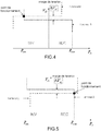
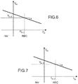
- the control of the DC voltage is distributed according to one of the characteristics illustrated on the Figures 6 and 7 .
- the terms "INV” and “REC” used on the Figures 2 to 7 correspond respectively to an operation inverter (“Inverter”) and rectifier (“Rectifier”).
- This control uses a “droop” mechanism to regulate the DC voltage in adjusting the power injections of the converters ( figure 6 ) or current injections ( figure 7 ).
- This expression is used to calculate the power injection in each DC node, when the voltage values are previously known.
- the nodes are power controllers or voltage controllers, which means that in a node the known variable is either the DC voltage or the DC power injection.
- a system of non-linear equations must then be solved. This is the role of the power transit calculation.
- the purpose of the power transit calculation is to achieve a stable operating point of the network by solving a system of non-linear equations. This calculation makes it possible to analyze the power systems and can be used to find a starting point for a dynamic system analysis or to do a contingency analysis.
- the equations can be rewritten using a resolution method chosen for example the technique of Newton Raphson.
- the generalized method offers the possibility of integrating a "droop" DC voltage control.
- the generalized method allows to include converters under distributed voltage control. This method makes it possible to obtain DC voltages. The unknown power injections can then be calculated.
- X dc , mod j X dc , mod - X dc , mod , callus
- the power transit resolution flow chart using this generalized method with voltage / power control is shown on the figure 10 .
- the HVDC network is started after a power transit calculation based on the master / slave strategy to compute the initial conditions. Then a more generalized algorithm adapted to the chosen strategy (master / slave, voltage margin or droop) is launched to calculate the new points of operation of the multiterminal network.
- a secondary control controls the frequency of the system and cross-border power exchanges back to the original desired values after 15 to 30 seconds if the requested power demand does not reach the reserve saturation limit.
- the DC voltage is controlled and must be kept within an acceptable margin of + 10%.
- Primary control tends to return to the balance power output-power consumption.
- the purpose of the secondary control is to reduce the voltage variation due to the first control.
- the secondary control approach has the effect of a parallel shift of the "droop" characteristic, which means that an offset is added, keeping the corresponding droop constant (slope).
- the DC voltage is set to a value determined during the application of the control secondary. Depending on this value (considered equal to 1 pu) the DC voltage in this node must increase or decrease and with it the DC voltage in the other nodes. Considering, for example, the first moment when the secondary control is applied, the DC voltage in node 3 must increase from 0.9960 pu to 1 pu. Since the DC power in the nodes 1 and 2 is kept constant, increasing their voltages DC causes the decrease of their injected DC currents, which causes a reduction of the link losses. Thus, and since the master converter is responsible for achieving the power balance, the DC power injected into this node also decreases.
- the invention makes it possible to take into account the vulnerability of the new VSC-MTDC stable state after a disturbance following the application of the chosen "droop" primary control, a method using the master / slave DC voltage control strategy makes it possible to optimizing the values of the DC voltages without noticeable influence on the power distribution, by bringing the DC voltage of the converters back to a determined reference point.
Landscapes
- Engineering & Computer Science (AREA)
- Power Engineering (AREA)
- Direct Current Feeding And Distribution (AREA)
Claims (5)
- Verfahren zum Regeln eines HVDC-Netzwerks (high voltage direct current- Hochspannungs-Gleichstrom-Übertragung (HGÜ)) mit mehreren Endgeräten, umfassend eine Primärregelungsstrategie, bei der angestrebt wird, ein Gleichgewicht zwischen Leistungserzeugung und Leistungsverbrauch zu erlangen, und eine Sekundärregelungsstrategie, um jegliche Spannungsänderung aufgrund der Primärstrategie zu vermindern, dadurch gekennzeichnet, dass es die nachfolgenden Schritte umfasst:- in einer Zeitspanne t, die zwischen 0 und T liegt, Durchführen einer Leistungsübergangsberechnung im Normalbetrieb mit einem Knoten, der als Master-Umrichter erachtet wird,- zur Zeit t = T Erzeugen einer Störung in einem anderen als den vorherigen ersten Knoten,wobei- in der Zeitspanne t, die zwischen T und 2T liegt, eine Spannungsregelung "droop" wirksam ist und der Leistungsverlust auf die weiteren Knoten verteilt wird,- zur Zeit t = 2T, eine Sekundärregelung nach einer Master-Slave-Strategie angewandt wird, indem die Spannung auf ihren Wert vor der Störung festgelegt wird,- zur Zeit t = 3T die Leistungseinspeisung am ersten Knoten auf ihren Anfangswert, d. h. den Wert vor der Störung, zurückkehrt, und die Spannungsregelung "droop" wieder aktiviert wird,- zur Zeit t = 4T eine Sekundärregelung aktiviert wird, um die Änderung der Spannungen DC zu vermindern, indem eine Master-/Slave-Regelungsstrategie für die Spannung DC angewendet wird.
- Verfahren nach Anspruch 1, wobei bei der Primärstrategie eine Regelungsstrategie für die Spannung DC vom Typ "droop" angewendet wird.
- Verfahren nach einem der vorangehenden Ansprüche, wobei bei der Sekundärstrategie eine Regelungsstrategie für die Spannung DC gemäß der Topologie und der Leistung von zusammengeschalteten Knoten angewendet wird.
- Verfahren nach Anspruch 3, wobei die Regelungsstrategie für die Spannung DC eine Master-Slave-Strategie oder eine Spannungsbereichs-Strategie ist.
- Verfahren nach Anspruch 1, wobei T auf die Reaktionen der im Netz zusammengeschalteten Systeme angepasst ist.
Applications Claiming Priority (2)
| Application Number | Priority Date | Filing Date | Title |
|---|---|---|---|
| FR1260534A FR2997804B1 (fr) | 2012-11-06 | 2012-11-06 | Procede de controle d'un reseau multi-terminal vsc-hvdc |
| PCT/EP2013/072917 WO2014072246A1 (fr) | 2012-11-06 | 2013-11-04 | Procede de contrôle d'un reseau multi-terminal vsc-hvdc |
Publications (2)
| Publication Number | Publication Date |
|---|---|
| EP2917992A1 EP2917992A1 (de) | 2015-09-16 |
| EP2917992B1 true EP2917992B1 (de) | 2017-01-04 |
Family
ID=47624342
Family Applications (1)
| Application Number | Title | Priority Date | Filing Date |
|---|---|---|---|
| EP13789748.4A Active EP2917992B1 (de) | 2012-11-06 | 2013-11-04 | Verfahren zur steuerung eines vsc-hvdc-netzwerks mit mehreren endgeräten |
Country Status (3)
| Country | Link |
|---|---|
| EP (1) | EP2917992B1 (de) |
| FR (1) | FR2997804B1 (de) |
| WO (1) | WO2014072246A1 (de) |
Families Citing this family (7)
| Publication number | Priority date | Publication date | Assignee | Title |
|---|---|---|---|---|
| WO2016134319A1 (en) | 2015-02-19 | 2016-08-25 | Enphase Energy, Inc. | Method and apparatus for time-domain droop control with integrated phasor current control |
| WO2017077045A1 (en) * | 2015-11-06 | 2017-05-11 | Danmarks Tekniske Universitet | Method to predetermine current/power flow change in a dc grid |
| ES2711005B2 (es) * | 2017-10-25 | 2024-03-07 | Univ Madrid Carlos Iii | Método para el control distribuido de la frecuencia en un parque eólico offshore |
| FR3073989B1 (fr) * | 2017-11-17 | 2019-11-29 | Supergrid Institute | Dispositif de controle d'un terminal pour la compensation d'une perturbation en tension |
| CN108879650B (zh) * | 2018-06-27 | 2021-09-03 | 广东电网有限责任公司电力科学研究院 | 一种多端柔性直流输电系统的协调优化控制方法及装置 |
| CN110544954B (zh) * | 2019-09-27 | 2021-09-03 | 南方电网科学研究院有限责任公司 | 一种多端直流输电系统和传输路径选取方法 |
| CN111509760A (zh) * | 2020-05-15 | 2020-08-07 | 南方电网科学研究院有限责任公司 | 一种区域间电网互联用vsc虚拟同步方法及其系统 |
-
2012
- 2012-11-06 FR FR1260534A patent/FR2997804B1/fr active Active
-
2013
- 2013-11-04 WO PCT/EP2013/072917 patent/WO2014072246A1/fr active Application Filing
- 2013-11-04 EP EP13789748.4A patent/EP2917992B1/de active Active
Also Published As
| Publication number | Publication date |
|---|---|
| EP2917992A1 (de) | 2015-09-16 |
| FR2997804B1 (fr) | 2016-02-12 |
| WO2014072246A1 (fr) | 2014-05-15 |
| FR2997804A1 (fr) | 2014-05-09 |
Similar Documents
| Publication | Publication Date | Title |
|---|---|---|
| EP2917992B1 (de) | Verfahren zur steuerung eines vsc-hvdc-netzwerks mit mehreren endgeräten | |
| Augustine et al. | Control of photovoltaic‐based low‐voltage dc microgrid system for power sharing with modified droop algorithm | |
| US11527955B2 (en) | Systems, methods and devices for control of DC/DC converters and a standalone DC microgrid using artificial neural networks | |
| Beniwal et al. | Control and operation of a solar PV‐battery‐grid‐tied system in fixed and variable power mode | |
| EP2756577B1 (de) | Stabilisierung eines elektrischen dc netzes | |
| Aly et al. | Assessment of reactive power contribution of photovoltaic energy systems on voltage profile and stability of distribution systems | |
| Tang et al. | Analysis for step‐size optimisation on MPPT algorithm for photovoltaic systems | |
| Jibji‐Bukar et al. | Frequency support from photovoltaic power plants using offline maximum power point tracking and variable droop control | |
| US11631978B2 (en) | Real-time estimation of contributions from classes of energy generators in residual load signals | |
| EP3818606A1 (de) | Vorrichtung zur aktiven elektrischen kompensation | |
| US20210397762A1 (en) | Distribution grid admittance estimation with limited nonsynchronized measurements | |
| EP3598598B1 (de) | Verfahren und system zur bestimmung eines spannungszustands eines an wenigstens einer transformatorstation liegenden niederspannungsnetzes | |
| WO2019008275A1 (fr) | Convertisseur muni d'un module de gestion de l'energie en partie alternative | |
| WO2019097183A1 (fr) | Dispositif de controle d'un terminal pour la compensation d'une perturbation en tension | |
| EP3044865B1 (de) | Steuerungssystem für eine elektrische ladung | |
| Mortezapour et al. | Adaptive primary droop control for islanded operation of hybrid AC–DC MGs | |
| Yue et al. | Assessing cloud transient impacts of solar and battery energy systems on grid inertial responses | |
| EP3454142B1 (de) | Verfahren zur überwachung und steuerung eines elektrischen stromnetzes | |
| Das et al. | A probabilistic approach to assess the adequacy of wind and solar energy | |
| FR3028080A1 (fr) | Methode de gestion de la distribution d'energie electrique en temps reel sur un reseau ilote | |
| Deng et al. | Distributed secondary optimal control for self‐maintaining microgrids on pelagic islands | |
| EP3510686A1 (de) | System zum analogen allgemeinen ausgleichen für eine anordnung aus vorrichtungen zur speicherung von elektrischer energie mit kapazitivem effekt, wiederaufladbares speichermodul, elektrofahrzeug und elektrische anlage mit solch einem system | |
| EP2582002A2 (de) | Spannungsregulierungsverfahren in einem Netz, das dezentralisierte Quellen umfasst | |
| EP4026217B1 (de) | Verfahren zur steuerung eines hybriden systems und entsprechende vorrichtung | |
| FR3145658A1 (fr) | Boucle de contrôle-commande de statisme pour onduleur interfaçant une source d’énergie intermittente et un réseau électrique alternatif |
Legal Events
| Date | Code | Title | Description |
|---|---|---|---|
| PUAI | Public reference made under article 153(3) epc to a published international application that has entered the european phase |
Free format text: ORIGINAL CODE: 0009012 |
|
| 17P | Request for examination filed |
Effective date: 20150511 |
|
| AK | Designated contracting states |
Kind code of ref document: A1 Designated state(s): AL AT BE BG CH CY CZ DE DK EE ES FI FR GB GR HR HU IE IS IT LI LT LU LV MC MK MT NL NO PL PT RO RS SE SI SK SM TR |
|
| AX | Request for extension of the european patent |
Extension state: BA ME |
|
| DAX | Request for extension of the european patent (deleted) | ||
| RAP1 | Party data changed (applicant data changed or rights of an application transferred) |
Owner name: GENERAL ELECTRIC TECHNOLOGY GMBH |
|
| GRAP | Despatch of communication of intention to grant a patent |
Free format text: ORIGINAL CODE: EPIDOSNIGR1 |
|
| GRAJ | Information related to disapproval of communication of intention to grant by the applicant or resumption of examination proceedings by the epo deleted |
Free format text: ORIGINAL CODE: EPIDOSDIGR1 |
|
| GRAP | Despatch of communication of intention to grant a patent |
Free format text: ORIGINAL CODE: EPIDOSNIGR1 |
|
| INTG | Intention to grant announced |
Effective date: 20160622 |
|
| INTG | Intention to grant announced |
Effective date: 20160718 |
|
| GRAS | Grant fee paid |
Free format text: ORIGINAL CODE: EPIDOSNIGR3 |
|
| STAA | Information on the status of an ep patent application or granted ep patent |
Free format text: STATUS: GRANT OF PATENT IS INTENDED |
|
| GRAA | (expected) grant |
Free format text: ORIGINAL CODE: 0009210 |
|
| STAA | Information on the status of an ep patent application or granted ep patent |
Free format text: STATUS: THE PATENT HAS BEEN GRANTED |
|
| AK | Designated contracting states |
Kind code of ref document: B1 Designated state(s): AL AT BE BG CH CY CZ DE DK EE ES FI FR GB GR HR HU IE IS IT LI LT LU LV MC MK MT NL NO PL PT RO RS SE SI SK SM TR |
|
| REG | Reference to a national code |
Ref country code: GB Ref legal event code: FG4D Free format text: NOT ENGLISH |
|
| REG | Reference to a national code |
Ref country code: CH Ref legal event code: EP |
|
| REG | Reference to a national code |
Ref country code: AT Ref legal event code: REF Ref document number: 860112 Country of ref document: AT Kind code of ref document: T Effective date: 20170115 |
|
| REG | Reference to a national code |
Ref country code: IE Ref legal event code: FG4D Free format text: LANGUAGE OF EP DOCUMENT: FRENCH |
|
| REG | Reference to a national code |
Ref country code: DE Ref legal event code: R096 Ref document number: 602013016254 Country of ref document: DE |
|
| REG | Reference to a national code |
Ref country code: SE Ref legal event code: TRGR |
|
| REG | Reference to a national code |
Ref country code: LT Ref legal event code: MG4D Ref country code: NL Ref legal event code: MP Effective date: 20170104 |
|
| REG | Reference to a national code |
Ref country code: AT Ref legal event code: MK05 Ref document number: 860112 Country of ref document: AT Kind code of ref document: T Effective date: 20170104 |
|
| PG25 | Lapsed in a contracting state [announced via postgrant information from national office to epo] |
Ref country code: NL Free format text: LAPSE BECAUSE OF FAILURE TO SUBMIT A TRANSLATION OF THE DESCRIPTION OR TO PAY THE FEE WITHIN THE PRESCRIBED TIME-LIMIT Effective date: 20170104 |
|
| PG25 | Lapsed in a contracting state [announced via postgrant information from national office to epo] |
Ref country code: IS Free format text: LAPSE BECAUSE OF FAILURE TO SUBMIT A TRANSLATION OF THE DESCRIPTION OR TO PAY THE FEE WITHIN THE PRESCRIBED TIME-LIMIT Effective date: 20170504 Ref country code: FI Free format text: LAPSE BECAUSE OF FAILURE TO SUBMIT A TRANSLATION OF THE DESCRIPTION OR TO PAY THE FEE WITHIN THE PRESCRIBED TIME-LIMIT Effective date: 20170104 Ref country code: GR Free format text: LAPSE BECAUSE OF FAILURE TO SUBMIT A TRANSLATION OF THE DESCRIPTION OR TO PAY THE FEE WITHIN THE PRESCRIBED TIME-LIMIT Effective date: 20170405 Ref country code: NO Free format text: LAPSE BECAUSE OF FAILURE TO SUBMIT A TRANSLATION OF THE DESCRIPTION OR TO PAY THE FEE WITHIN THE PRESCRIBED TIME-LIMIT Effective date: 20170404 Ref country code: HR Free format text: LAPSE BECAUSE OF FAILURE TO SUBMIT A TRANSLATION OF THE DESCRIPTION OR TO PAY THE FEE WITHIN THE PRESCRIBED TIME-LIMIT Effective date: 20170104 Ref country code: LT Free format text: LAPSE BECAUSE OF FAILURE TO SUBMIT A TRANSLATION OF THE DESCRIPTION OR TO PAY THE FEE WITHIN THE PRESCRIBED TIME-LIMIT Effective date: 20170104 |
|
| PG25 | Lapsed in a contracting state [announced via postgrant information from national office to epo] |
Ref country code: BG Free format text: LAPSE BECAUSE OF FAILURE TO SUBMIT A TRANSLATION OF THE DESCRIPTION OR TO PAY THE FEE WITHIN THE PRESCRIBED TIME-LIMIT Effective date: 20170404 Ref country code: AT Free format text: LAPSE BECAUSE OF FAILURE TO SUBMIT A TRANSLATION OF THE DESCRIPTION OR TO PAY THE FEE WITHIN THE PRESCRIBED TIME-LIMIT Effective date: 20170104 Ref country code: PT Free format text: LAPSE BECAUSE OF FAILURE TO SUBMIT A TRANSLATION OF THE DESCRIPTION OR TO PAY THE FEE WITHIN THE PRESCRIBED TIME-LIMIT Effective date: 20170504 Ref country code: LV Free format text: LAPSE BECAUSE OF FAILURE TO SUBMIT A TRANSLATION OF THE DESCRIPTION OR TO PAY THE FEE WITHIN THE PRESCRIBED TIME-LIMIT Effective date: 20170104 Ref country code: ES Free format text: LAPSE BECAUSE OF FAILURE TO SUBMIT A TRANSLATION OF THE DESCRIPTION OR TO PAY THE FEE WITHIN THE PRESCRIBED TIME-LIMIT Effective date: 20170104 Ref country code: PL Free format text: LAPSE BECAUSE OF FAILURE TO SUBMIT A TRANSLATION OF THE DESCRIPTION OR TO PAY THE FEE WITHIN THE PRESCRIBED TIME-LIMIT Effective date: 20170104 Ref country code: RS Free format text: LAPSE BECAUSE OF FAILURE TO SUBMIT A TRANSLATION OF THE DESCRIPTION OR TO PAY THE FEE WITHIN THE PRESCRIBED TIME-LIMIT Effective date: 20170104 |
|
| REG | Reference to a national code |
Ref country code: DE Ref legal event code: R097 Ref document number: 602013016254 Country of ref document: DE |
|
| PG25 | Lapsed in a contracting state [announced via postgrant information from national office to epo] |
Ref country code: IT Free format text: LAPSE BECAUSE OF FAILURE TO SUBMIT A TRANSLATION OF THE DESCRIPTION OR TO PAY THE FEE WITHIN THE PRESCRIBED TIME-LIMIT Effective date: 20170104 Ref country code: CZ Free format text: LAPSE BECAUSE OF FAILURE TO SUBMIT A TRANSLATION OF THE DESCRIPTION OR TO PAY THE FEE WITHIN THE PRESCRIBED TIME-LIMIT Effective date: 20170104 Ref country code: SK Free format text: LAPSE BECAUSE OF FAILURE TO SUBMIT A TRANSLATION OF THE DESCRIPTION OR TO PAY THE FEE WITHIN THE PRESCRIBED TIME-LIMIT Effective date: 20170104 Ref country code: RO Free format text: LAPSE BECAUSE OF FAILURE TO SUBMIT A TRANSLATION OF THE DESCRIPTION OR TO PAY THE FEE WITHIN THE PRESCRIBED TIME-LIMIT Effective date: 20170104 Ref country code: EE Free format text: LAPSE BECAUSE OF FAILURE TO SUBMIT A TRANSLATION OF THE DESCRIPTION OR TO PAY THE FEE WITHIN THE PRESCRIBED TIME-LIMIT Effective date: 20170104 |
|
| PLBE | No opposition filed within time limit |
Free format text: ORIGINAL CODE: 0009261 |
|
| STAA | Information on the status of an ep patent application or granted ep patent |
Free format text: STATUS: NO OPPOSITION FILED WITHIN TIME LIMIT |
|
| REG | Reference to a national code |
Ref country code: FR Ref legal event code: PLFP Year of fee payment: 5 |
|
| PG25 | Lapsed in a contracting state [announced via postgrant information from national office to epo] |
Ref country code: DK Free format text: LAPSE BECAUSE OF FAILURE TO SUBMIT A TRANSLATION OF THE DESCRIPTION OR TO PAY THE FEE WITHIN THE PRESCRIBED TIME-LIMIT Effective date: 20170104 Ref country code: SM Free format text: LAPSE BECAUSE OF FAILURE TO SUBMIT A TRANSLATION OF THE DESCRIPTION OR TO PAY THE FEE WITHIN THE PRESCRIBED TIME-LIMIT Effective date: 20170104 |
|
| 26N | No opposition filed |
Effective date: 20171005 |
|
| PG25 | Lapsed in a contracting state [announced via postgrant information from national office to epo] |
Ref country code: SI Free format text: LAPSE BECAUSE OF FAILURE TO SUBMIT A TRANSLATION OF THE DESCRIPTION OR TO PAY THE FEE WITHIN THE PRESCRIBED TIME-LIMIT Effective date: 20170104 |
|
| PG25 | Lapsed in a contracting state [announced via postgrant information from national office to epo] |
Ref country code: MC Free format text: LAPSE BECAUSE OF FAILURE TO SUBMIT A TRANSLATION OF THE DESCRIPTION OR TO PAY THE FEE WITHIN THE PRESCRIBED TIME-LIMIT Effective date: 20170104 |
|
| PG25 | Lapsed in a contracting state [announced via postgrant information from national office to epo] |
Ref country code: CH Free format text: LAPSE BECAUSE OF NON-PAYMENT OF DUE FEES Effective date: 20171130 Ref country code: LI Free format text: LAPSE BECAUSE OF NON-PAYMENT OF DUE FEES Effective date: 20171130 |
|
| PG25 | Lapsed in a contracting state [announced via postgrant information from national office to epo] |
Ref country code: LU Free format text: LAPSE BECAUSE OF NON-PAYMENT OF DUE FEES Effective date: 20171104 |
|
| REG | Reference to a national code |
Ref country code: BE Ref legal event code: MM Effective date: 20171130 |
|
| REG | Reference to a national code |
Ref country code: IE Ref legal event code: MM4A |
|
| PG25 | Lapsed in a contracting state [announced via postgrant information from national office to epo] |
Ref country code: MT Free format text: LAPSE BECAUSE OF FAILURE TO SUBMIT A TRANSLATION OF THE DESCRIPTION OR TO PAY THE FEE WITHIN THE PRESCRIBED TIME-LIMIT Effective date: 20170104 |
|
| REG | Reference to a national code |
Ref country code: FR Ref legal event code: PLFP Year of fee payment: 6 |
|
| PG25 | Lapsed in a contracting state [announced via postgrant information from national office to epo] |
Ref country code: IE Free format text: LAPSE BECAUSE OF NON-PAYMENT OF DUE FEES Effective date: 20171104 |
|
| PG25 | Lapsed in a contracting state [announced via postgrant information from national office to epo] |
Ref country code: BE Free format text: LAPSE BECAUSE OF NON-PAYMENT OF DUE FEES Effective date: 20171130 |
|
| PG25 | Lapsed in a contracting state [announced via postgrant information from national office to epo] |
Ref country code: HU Free format text: LAPSE BECAUSE OF FAILURE TO SUBMIT A TRANSLATION OF THE DESCRIPTION OR TO PAY THE FEE WITHIN THE PRESCRIBED TIME-LIMIT; INVALID AB INITIO Effective date: 20131104 |
|
| PG25 | Lapsed in a contracting state [announced via postgrant information from national office to epo] |
Ref country code: CY Free format text: LAPSE BECAUSE OF FAILURE TO SUBMIT A TRANSLATION OF THE DESCRIPTION OR TO PAY THE FEE WITHIN THE PRESCRIBED TIME-LIMIT Effective date: 20170104 |
|
| PG25 | Lapsed in a contracting state [announced via postgrant information from national office to epo] |
Ref country code: MK Free format text: LAPSE BECAUSE OF FAILURE TO SUBMIT A TRANSLATION OF THE DESCRIPTION OR TO PAY THE FEE WITHIN THE PRESCRIBED TIME-LIMIT Effective date: 20170104 |
|
| PG25 | Lapsed in a contracting state [announced via postgrant information from national office to epo] |
Ref country code: TR Free format text: LAPSE BECAUSE OF FAILURE TO SUBMIT A TRANSLATION OF THE DESCRIPTION OR TO PAY THE FEE WITHIN THE PRESCRIBED TIME-LIMIT Effective date: 20170104 |
|
| PG25 | Lapsed in a contracting state [announced via postgrant information from national office to epo] |
Ref country code: AL Free format text: LAPSE BECAUSE OF FAILURE TO SUBMIT A TRANSLATION OF THE DESCRIPTION OR TO PAY THE FEE WITHIN THE PRESCRIBED TIME-LIMIT Effective date: 20170104 |
|
| P01 | Opt-out of the competence of the unified patent court (upc) registered |
Effective date: 20230522 |
|
| REG | Reference to a national code |
Ref country code: DE Ref legal event code: R082 Ref document number: 602013016254 Country of ref document: DE Representative=s name: KANDLBINDER, MARKUS, DIPL.-PHYS., DE |
|
| PGFP | Annual fee paid to national office [announced via postgrant information from national office to epo] |
Ref country code: GB Payment date: 20231019 Year of fee payment: 11 |
|
| PGFP | Annual fee paid to national office [announced via postgrant information from national office to epo] |
Ref country code: SE Payment date: 20231020 Year of fee payment: 11 Ref country code: FR Payment date: 20231019 Year of fee payment: 11 Ref country code: DE Payment date: 20231019 Year of fee payment: 11 |