EP2917122B1 - Behälter, verschluss und verpackung - Google Patents
Behälter, verschluss und verpackung Download PDFInfo
- Publication number
- EP2917122B1 EP2917122B1 EP13762718.8A EP13762718A EP2917122B1 EP 2917122 B1 EP2917122 B1 EP 2917122B1 EP 13762718 A EP13762718 A EP 13762718A EP 2917122 B1 EP2917122 B1 EP 2917122B1
- Authority
- EP
- European Patent Office
- Prior art keywords
- annular
- container
- axially
- closure
- inner shell
- Prior art date
- Legal status (The legal status is an assumption and is not a legal conclusion. Google has not performed a legal analysis and makes no representation as to the accuracy of the status listed.)
- Active
Links
- 239000011324 bead Substances 0.000 claims description 39
- 238000007789 sealing Methods 0.000 claims description 27
- 230000000717 retained effect Effects 0.000 claims description 2
- UQMRAFJOBWOFNS-UHFFFAOYSA-N butyl 2-(2,4-dichlorophenoxy)acetate Chemical compound CCCCOC(=O)COC1=CC=C(Cl)C=C1Cl UQMRAFJOBWOFNS-UHFFFAOYSA-N 0.000 description 33
- 238000010276 construction Methods 0.000 description 4
- 230000006835 compression Effects 0.000 description 3
- 238000007906 compression Methods 0.000 description 3
- 239000011521 glass Substances 0.000 description 3
- 239000002184 metal Substances 0.000 description 3
- CDBYLPFSWZWCQE-UHFFFAOYSA-L Sodium Carbonate Chemical compound [Na+].[Na+].[O-]C([O-])=O CDBYLPFSWZWCQE-UHFFFAOYSA-L 0.000 description 2
- 235000013405 beer Nutrition 0.000 description 2
- 239000007924 injection Substances 0.000 description 2
- 230000004048 modification Effects 0.000 description 2
- 238000012986 modification Methods 0.000 description 2
- 244000025254 Cannabis sativa Species 0.000 description 1
- 230000004323 axial length Effects 0.000 description 1
- 235000013361 beverage Nutrition 0.000 description 1
- 238000000071 blow moulding Methods 0.000 description 1
- 235000014171 carbonated beverage Nutrition 0.000 description 1
- 230000008878 coupling Effects 0.000 description 1
- 238000010168 coupling process Methods 0.000 description 1
- 238000005859 coupling reaction Methods 0.000 description 1
- 238000002347 injection Methods 0.000 description 1
- 238000001746 injection moulding Methods 0.000 description 1
- 239000007788 liquid Substances 0.000 description 1
- 238000004519 manufacturing process Methods 0.000 description 1
Images


Classifications
-
- B—PERFORMING OPERATIONS; TRANSPORTING
- B65—CONVEYING; PACKING; STORING; HANDLING THIN OR FILAMENTARY MATERIAL
- B65D—CONTAINERS FOR STORAGE OR TRANSPORT OF ARTICLES OR MATERIALS, e.g. BAGS, BARRELS, BOTTLES, BOXES, CANS, CARTONS, CRATES, DRUMS, JARS, TANKS, HOPPERS, FORWARDING CONTAINERS; ACCESSORIES, CLOSURES, OR FITTINGS THEREFOR; PACKAGING ELEMENTS; PACKAGES
- B65D41/00—Caps, e.g. crown caps or crown seals, i.e. members having parts arranged for engagement with the external periphery of a neck or wall defining a pouring opening or discharge aperture; Protective cap-like covers for closure members, e.g. decorative covers of metal foil or paper
- B65D41/32—Caps or cap-like covers with lines of weakness, tearing-strips, tags, or like opening or removal devices, e.g. to facilitate formation of pouring openings
- B65D41/34—Threaded or like caps or cap-like covers provided with tamper elements formed in, or attached to, the closure skirt
-
- B—PERFORMING OPERATIONS; TRANSPORTING
- B65—CONVEYING; PACKING; STORING; HANDLING THIN OR FILAMENTARY MATERIAL
- B65D—CONTAINERS FOR STORAGE OR TRANSPORT OF ARTICLES OR MATERIALS, e.g. BAGS, BARRELS, BOTTLES, BOXES, CANS, CARTONS, CRATES, DRUMS, JARS, TANKS, HOPPERS, FORWARDING CONTAINERS; ACCESSORIES, CLOSURES, OR FITTINGS THEREFOR; PACKAGING ELEMENTS; PACKAGES
- B65D1/00—Containers having bodies formed in one piece, e.g. by casting metallic material, by moulding plastics, by blowing vitreous material, by throwing ceramic material, by moulding pulped fibrous material, by deep-drawing operations performed on sheet material
- B65D1/02—Bottles or similar containers with necks or like restricted apertures, designed for pouring contents
- B65D1/0223—Bottles or similar containers with necks or like restricted apertures, designed for pouring contents characterised by shape
- B65D1/023—Neck construction
- B65D1/0246—Closure retaining means, e.g. beads, screw-threads
-
- B—PERFORMING OPERATIONS; TRANSPORTING
- B65—CONVEYING; PACKING; STORING; HANDLING THIN OR FILAMENTARY MATERIAL
- B65D—CONTAINERS FOR STORAGE OR TRANSPORT OF ARTICLES OR MATERIALS, e.g. BAGS, BARRELS, BOTTLES, BOXES, CANS, CARTONS, CRATES, DRUMS, JARS, TANKS, HOPPERS, FORWARDING CONTAINERS; ACCESSORIES, CLOSURES, OR FITTINGS THEREFOR; PACKAGING ELEMENTS; PACKAGES
- B65D41/00—Caps, e.g. crown caps or crown seals, i.e. members having parts arranged for engagement with the external periphery of a neck or wall defining a pouring opening or discharge aperture; Protective cap-like covers for closure members, e.g. decorative covers of metal foil or paper
- B65D41/02—Caps or cap-like covers without lines of weakness, tearing strips, tags, or like opening or removal devices
-
- B—PERFORMING OPERATIONS; TRANSPORTING
- B65—CONVEYING; PACKING; STORING; HANDLING THIN OR FILAMENTARY MATERIAL
- B65D—CONTAINERS FOR STORAGE OR TRANSPORT OF ARTICLES OR MATERIALS, e.g. BAGS, BARRELS, BOTTLES, BOXES, CANS, CARTONS, CRATES, DRUMS, JARS, TANKS, HOPPERS, FORWARDING CONTAINERS; ACCESSORIES, CLOSURES, OR FITTINGS THEREFOR; PACKAGING ELEMENTS; PACKAGES
- B65D51/00—Closures not otherwise provided for
- B65D51/16—Closures not otherwise provided for with means for venting air or gas
- B65D51/1672—Closures not otherwise provided for with means for venting air or gas whereby venting occurs by manual actuation of the closure or other element
- B65D51/1688—Venting occurring during initial closing or opening of the container, by means of a passage for the escape of gas between the closure and the lip of the container mouth, e.g. interrupted threads
Definitions
- the present disclosure is directed to packages and, more particularly, containers, and closures for containers.
- Container closures include crimpable closures, for example, securable to crown finishes of bottles.
- U.S. Patent 3,494,093 illustrates an example crimp-type closure.
- Container closures also include threadable closures, for example, securable to threaded finishes of bottles.
- U.S. Patents 2,789,719 and 4,337,678 illustrate examples of thread-type closures.
- FR2906228A1 discloses a molded snap-on cap for a container neck and including a tubular skirt having an opening tab projecting radially outwardly from a front part of the skirt and diametrically opposed clips projecting radially inwardly from side parts of the skirt and fixable on a projecting outer edge of the neck.
- US3592349 discloses a plastic cap including a top portion, an inner skirt for interference fit in an opening of a container neck, and an outer skirt with an internal shoulder for cooperating with an external shoulder on the container neck to retain the cap on the container neck.
- EP0427688A1 discloses a screw top closure for application to a neck of a container and including an outer lid with internal threading and an inner lid with external threading.
- the inner lid has an upper part to support the lid and inner and outer tubular flanges protruding downwardly therefrom and defining an open pocket for receipt of the container neck.
- the inner lid has an upper portion and an inner tubular flange protruding downwardly therefrom and insertable into the lid attachment for sealing against the inner tubular flange.
- EP0661218A1 discloses a plastic closure cap for sealing a container at its orifice, and including a cap base having an inner surface, a cylindrical cap wall extending from the base, and an internal seal extending from the inner surface of the base.
- the seal includes a radially outer surface with a surrounding sealing portion on its outer edge defining a maximum outer diameter for internal sealing of the container orifice and includes an insert portion beneath the sealing portion.
- the insert portion includes a compression zone to engage the container orifice and that is compressible when the insert portion is inserted into the orifice.
- the radially outer surface of the seal also includes at least one vent recess axially below the sealing portion and extending at least over the entire height of the compression zone.
- US2398553 discloses a closure member for a container and including a domed outer cover having a flange, and a domed inner body having a sealing ring and outwardly extending tabs with embossed segments of screw threads for threading to the container.
- a general object of the present disclosure in accordance with one aspect of the disclosure, is to provide a closure that is resalable to a container, is relatively comfortable to remove, and permits pressure in the container to be relieved before the closure is disengaged from the container, and to provide a container that has a crown finish that provides good "lip-feel" to one who consumes product directly from the container.
- the present disclosure embodies a number of aspects that can be implemented separately from or in combination with each other.
- a closure for a container having a neck with an external bead in accordance with one aspect of the disclosure includes an inner shell and an outer shell coupled to the inner shell.
- the inner shell includes an inner shell base wall having a central passage, and an annular skirt extending axially from the base wall radially outward of the central passage and having an outer surface and at least one external thread segment projecting from the outer surface.
- the outer shell includes an outer shell base wall, a plug seal extending axially from the base wall through the central passage of the inner shell base wall, and an annular outer skirt extending axially from the base wall radially outward of the plug seal and having at least one internal thread segment for threaded engagement with the at least one external thread segment of the inner shell.
- a container that includes a body, a shoulder extending from the body, and a neck extending from the shoulder.
- the neck includes an axial outward end surface, an inner annular sealing surface axially spaced from the axial outward end surface, an inner annular relief axially between the annular sealing surface and the axial outward end surface and having a larger diameter than that of the inner annular sealing surface, an outer annular bead axially between the shoulder and the axial outward end surface and axially overlapping the inner annular relief, wherein the outer annular bead includes a radial outer surface, an axial outward surface, and an axial inward surface.
- the neck also includes an outer annular relief axially between the shoulder and the outer annular bead.
- a closure for a container having a mouth surrounded by an external bead includes an inner shell having an annular skirt with external thread segments and a plurality of angularly spaced grip petals, and an outer shell having an annular skirt with internal thread segments for threaded engagement with the external thread segments on the inner shell such that an edge of the skirt on the outer shell engages the grip petals and hooks the grip petals over the external bead upon tightening of the outer shell over the inner shell.
- a closure inner shell that includes an inner shell base wall having a central passage, and an annular skirt extending axially from the base wall radially outward of the central passage and having an outer surface and at least one external thread segment projecting from the outer surface.
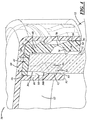
- FIG. 1 illustrates a package 10 including a container 12, and a closure 14 coupled to the container 12.
- the package 10 includes a longitudinal axis A along which the container 12 generally extends, also along which the closure 14 may be applied to and removed from the container 12, and about which a portion of the closure 14 may be rotated.
- the package 10 may include a beverage package, and may be used to contain pressurized liquid, for example, carbonated beverages, like beer, soda, etc. Accordingly, the package 10 may be a closed beer bottle, closed soda bottle, or the like. In other embodiments, the package 10 may include any other suitable type of closed container for any suitable purpose.
- directional words such as top, bottom, upper, upward, downward, lower, radial, circumferential, lateral, longitudinal, transverse, vertical, horizontal, and the like are employed by way of description and not necessarily limitation.
- the container 12 may be of one-piece integrally formed construction, preferably grass, plastic, or metal construction.
- integrally formed construction does not exclude one-piece integrally molded layered glass constructions of the type disclosed for example in U.S. Patent 4,740,401 , or one-piece glass or metal bottles to which other structure is added after the bottle-forming operation.
- the container 12 may be fabricated in press-and-blow or blow-and-blow glass container manufacturing operations, in a plastic injection and/or blow molding operation, in a metal drawing operation, or in any other suitable manner.
- the container 12 includes a base (not shown) on which the container 12 may be supported, a body 16 extending axially from the base, a shoulder 18 extending radially and axially from the body 16, and a neck 20 extending axially from the shoulder 18.
- the term axial includes oriented generally along a longitudinal axis of the closure, container, or package and may include but is not limited to a direction that is strictly parallel to the axis.
- the neck 20 includes a lip or axial outward end surface 22 ( FIG.
- an outer annular bead 24 axially between the shoulder 18 and the axial outward end surface 22 and including a radial outer surface 26, an axial outward surface 28 that may be the same as or coplanar with the axial outward end surface 22 of the neck 20, an axial inward surface 30, and an outer annular reduced diameter portion or relief 32 axially between the shoulder 18 and the outer annular bead 24.
- the neck 20 also includes an inner annular sealing surface 34 axially spaced from the axial outward end surface 22, and an inner annular relief 36 axially between the inner annular sealing surface 34 and the axial outward end surface 22 and having a larger diameter than that of the inner annular sealing surface 34.
- the annular relief 36 may axially overlap the outer annular bead 24 and may include an annular surface 36a and a tapered surface 36b between the annular surface 36a and the sealing surface 34.
- the container 12 of this embodiment also includes one or more reliefs 38 in the radial outer surface 26 of the outer annular bead 24 and axially extending through the axial outward surface 28 of the outer annular bead 24.
- the relief(s) 38 also may axially extend through the axial inward surface 30 of the bead 24.
- the neck 20 also may include a mouth 29 ( FIG. 3 ) between the axial outward surface 22 and the inner annular relief 36.
- the bead 24 may be relatively tall for good "lip feel".
- the axial height or length of the bead 24 may be at least 2,03 mm (0.080") in axial length.
- the relief 38 and the lug 5 8 could be reversed, such that the lug 58 could be carried on the container neck and the relief 38 could be carried by the closure shell.
- the axial outward surface 22, the bead 24, and the mouth 29 may be referred to as the "finish" of the container 12.
- the finish also may include corresponding one or more interior portions of the neck 20, for example, the inner annular relief 36 and at least a portion of the sealing surface 34.
- the closure 14 is a multi-piece closure and, in particular, may be a two-piece closure, for example, including only two shells.
- the closure 14 includes an inner shell 40, and an outer shell 42 coupled to the inner shell 40.
- the inner shell 40 secures directly to the container 12, and the outer shell 42 secures directly to the inner shell 40 and sealingly engages directly with the container 12.
- the inner and outer shells 40, 42 may be composed of any suitable plastic(s) and may be injection molded, compression molded, or produced in any other suitable manner.
- the inner shell 40 includes an inner shell base wall 44 extending transversely with respect to the axis A having a central passage 46 with an inner diameter, and an annular skirt 48 extending axially from the base wall 44 radially outward of the central passage 46.
- transverse may mean disposed at some angle with respect to a longitudinal axis of the closure, container, or package and along any direction intersecting the closure, container, or package, and may include but is not limited to a radial direction.
- the skirt 48 ( FIG. 2 ) includes an upper or first axial end 50 at the base wall 44, a lower or second axial end 52, and inner and outer surfaces 54, 56 extending therebetween.
- the skirt 48 also includes one or more internal lugs 58 ( FIG.
- the skirt 48 further includes one or more external thread segments 60 projecting from the outer surface 56.
- thread segment includes whole, partial, multiple, and/or an interrupted thread and/or thread segment.
- the inner shell 40 also includes a plurality of petals 62 extending from the annular skirt 48, for example from the axially lower end 52, for gripping a corresponding portion of the container 12.
- the petals 62 are angularly or circumferentially spaced from one another, are circumferentially adjacent to one another with circumferential spaces 63 therebetween, and extend axially and radially outwardly in a free state of the inner shell 40.
- the petals 62 may include two or more petals, for example, four, six, eight, ten, twelve petals, or any other suitable quantity of petals.
- the petals 62 may include adjacent circumferential side surfaces 64 ( FIG. 2 ), radially inner and outer surfaces 66, 68, and frustoconical surfaces 70 ( FIG.
- the skirt 48 also may include radially inner incurvate surfaces 72 adjacent the axially lower end 52 of the skirt 48 and establishing a thinned wall 74 connecting the petals 62 to the lower end 52 of the skirt 48, and a radially inward facing shoulder 76 and an axially outward facing shoulder 78.
- the axially outward facing shoulder 78 may be tapered from the radially inward surface 66 upward to the radially inward facing shoulder 76.
- the shoulders 78 of the petals 62 engage the axial inward surface 30 of the outer annular bead 24 to retain the closure 14 on the container 12.
- the shell 40 may be molded so that the petals 62 extend axially and radially outwardly from the annular skirt 48 in a rest or free state, for example, as shown in FIG. 2 . Accordingly, the petals 62 may be flexible radially inwardly and may have memory in that they resiliently return radially outwardly to their molded rest state.
- the outer shell 42 includes an outer shell base wall 80, an annular inner skirt 82 extending axially from the base wall 80 through the central passage 46 of the inner shell 40 base wall 44 to retain the inner shell 40 to the outer shell 42, and an annular outer skirt 84 extending axially from the base wall 80 radially outward of the inner skirt 82 and having one or more internal thread segments 86 for threaded engagement with the external thread segment(s) 60 of the inner shell 40.
- the annular inner skirt 82 also may serve as an annular seal wall or plug seal for sliding contact or engagement with the annular sealing surface 34 of the container neck 20 when the closure 14 is applied to the container 12.
- the inner skirt 82 includes an annular wall 88 having an outer surface 90 with an outer diameter less than the inner diameter of the central passage 46.
- the inner skirt 82 also includes an annular enlargement 92 extending radially outwardly from the annular wall 88 and having an outer surface 94 with an outer diameter greater than the inner diameter of the central passage 46.
- the base wall 44 of the inner shell 40 is axially retained between the outer shell base wall 80 and the annular enlargement 92, which may be an annular seal.
- the container 12 may be sealed by the closure 14 by engagement of the plug seal of the outer shell 42 with the inner annular sealing surface 34 of the container neck 20.
- the container 12 also may be sealed by the closure 14 by engagement of the base wall 44 of the inner shell 40 with the lip 22 of the container neck 20, and/or by engagement of the inner surface 58 of the annular skirt 48 of the inner shell 40 with the outer surface 26 of the annular bead 24 of the container neck 20.
- the inner skirt 82 further may include a frustoconical or tapered surface 95 that may extend radially inwardly from the outer surface 94 and that may intersect an axial end surface 93 of the skirt 82.
- the skirt 82 also may include one or more vent channels or reliefs 96, for example, in the outer surface 94, to cooperate with the inner annular relief 36 of the container neck 20 to establish a pressure relief or vent path when the closure 14 is being removed from the container 12.
- the reliefs 96 also may intersect the tapered surface 95 wherein axially lower portions of the reliefs 96 are axially open and axially upper portions of the reliefs 96 are closed by the outer surface 94 of the annular enlargement 92.
- the outer skirt 84 of the outer shell 42 includes an axially lower end or edge 98 and a radially inner surface 99 adjacent to the edge 98 to engage the petals 62 of the inner shell 40 and fold or hook the petals 62 over the container neck external bead 24 when the closure 14 is being applied to the container 12 such that the outer shell 42 is being tightened to the inner shell 40.
- the edge 98 may axially engage the tapers 70 to gradually fold the petals 62 into engagement with the container bead 24.
- the closure 14 may be assembled or preassembled and then applied to the container 12.
- the annular inner skirt 82 of the outer shell 42 may be resilient and interference fit through the central passage 46 of the base wall 44 of the inner shell 40 so as to assemble the inner shell 40 to the outer shell 42.
- the assembled closure 14 may be located over the container neck 20 wherein the annular inner skirt 82 of the outer shell 42 is inserted into the mouth 29 of the container neck 20, the petals 62 are located around the container neck 20, and the internal lugs 58 of the inner shell 40 are located in the corresponding reliefs 38 in the container neck 20.
- the outer shell 42 may be rotated relative to the inner shell 40 so that the internal threads 86 of the outer shell 42 threadingly engage the external threads 60 of the inner shell 40.
- rotation of the outer shell 42 continues such that the annular outer skirt 84 of the outer shell 42 engages the petals 62 to fold or hook the petals 62 over the external bead 24 of the container neck 20 upon tightening of the outer shell 42 to the inner shell 40.
- the closure 14 is fastened and sealed to the container 12. More particularly, the outer shell 42 fastens to the inner shell 40 to cause fastening of the inner shell 40 to the container 12 while the inner skirt 82 of the outer shell 42 seals to the container 12.
- the closure 14 may be removed from the container 12.
- the outer shell 42 may be rotated to threadingly disengage the internal thread segments 86 of the outer shell 42 from the external thread segments 60 of the inner shell 40.
- the inner skirt 82 slides axially along the sealing surface 34 of the container 12 and the relief(s) 96 in the inner skirt 82 axially overlap with the inner annular relief 36 of the container neck 20 at a desired spacing between the shells 40, 42 and thereby cooperate to establish a vent path to vent the container 12 to atmosphere before the petals 62 of the inner shell 40 completely disengage from the container neck bead 24.
- the outer skirt 84 of the outer shell 42 moves away from the petals 62 to allow the resilient petals 62 to resiliently unfold or return to their free state in which they extend axially and radially outwardly from the annular skirt 48 of the inner shell 40 and thereby release from the container 12.
- the inner shell lugs 58 cooperate with the reliefs 38 in the container bead 24 to prevent the inner skirt 40 from rotating relative to the container 12 as the outer shell 42 is unscrewed from the inner shell 40.
- the annular inner skirt 82 disengages from the inner sealing surface 34 of the container neck 20. Accordingly, the closure 14 can be pulled away from the container 12 as shown in FIG. 7 , wherein a pulling force exerted on the outer shell 42 causes the inner shell 40 to be pulled away from the container 12 by way of the coupling between the outer shell 42 and the inner shell 40. Thereafter, the closure 14 may be reapplied and resealed to the container 12.
- the package 10 includes a container neck without threads, but includes a closure that operates in a familiar screw-on, screw-off manner.
Landscapes
- Engineering & Computer Science (AREA)
- Mechanical Engineering (AREA)
- Ceramic Engineering (AREA)
- Closures For Containers (AREA)
- Containers Having Bodies Formed In One Piece (AREA)
- Lift-Guide Devices, And Elevator Ropes And Cables (AREA)
- Turbine Rotor Nozzle Sealing (AREA)
- Pressure Vessels And Lids Thereof (AREA)
Claims (20)
- Behälter (12), welcher umfasst:einen Körper (16),eine sich von dem Körper aus erstreckende Schulter (18) undeinen sich von der Schulter aus erstreckenden Hals (20), welcher aufweist:eine axial nach außen gerichtete Endfläche (22),eine innere ringförmige Dichtfläche (34), die von der axial nach außen gerichteten Endfläche in axialer Richtung beabstandet ist,eine innere ringförmige Aussparung (36), die in axialer Richtung zwischen der ringförmigen Dichtfläche und der axial nach außen gerichteten Endfläche ausgebildet ist und einen größeren Durchmesser als die innere ringförmige Dichtfläche aufweist,einen äußeren ringförmigen Wulst (24), der in axialer Richtung zwischen der Schulter und der axial nach außen gerichteten Endfläche ausgebildet ist und die innere ringförmige Aussparung in axialer Richtung überlappt, wobei der äußere ringförmige Wulst eine radial außenseitige Oberfläche (26), eine axial auswärts gerichtete Oberfläche (28) und eine axial einwärts gerichtete Oberfläche (30) aufweist, undeine äußere ringförmige Aussparung (32), die in axialer Richtung zwischen der Schulter und dem äußeren ringförmigen Wulst ausgebildet ist, gekennzeichnet durchmindestens eine Aussparung (38) in der radial außenseitigen Oberfläche, die sich außerdem durch die axial auswärts gerichtete Oberfläche hindurch erstreckt.
- Behälter nach Anspruch 1, wobei sich die Aussparung außerdem durch die axial einwärts gerichtete Oberfläche des Wulstes hindurch erstreckt.
- Verpackung (10), die einen Behälter (12) umfasst,
umfassend:- einen Körper (16),- eine sich von dem Körper aus erstreckende Schulter (18) und- einen sich von der Schulter aus erstreckenden Hals (20), welcher aufweist:eine axial nach außen gerichtete Endfläche (22),eine innere ringförmige Dichtfläche (34), die von der axial nach außen gerichteten Endfläche in axialer Richtung beabstandet ist,eine innere ringförmige Aussparung (36), die in axialer Richtung zwischen der ringförmigen Dichtfläche und der axial nach außen gerichteten Endfläche ausgebildet ist und einen größeren Durchmesser aufweist als die innere ringförmige Dichtfläche,einen äußeren ringförmigen Wulst (24), der in axialer Richtung zwischen der Schulter und der axial nach außen gerichteten Endfläche ausgebildet ist und die innere ringförmige Aussparung in axialer Richtung überlappt, wobei der äußere ringförmige Wulst eine radial außenseitige Oberfläche (26), eine axial auswärts gerichtete Oberfläche (28) und eine axial einwärts gerichtete Oberfläche (30) aufweist, undeine äußere ringförmige Aussparung (32), die in axialer Richtung zwischen der Schulter und dem äußeren ringförmigen Wulst ausgebildet ist, und- einen mehrteiligen Verschluss (14), der mit dem Behälter verbunden ist und umfasst:eine innere Schale (40) mit einer Innenschalen-Bodenwandung (44), die eine mittige Durchführung (46) aufweist, und mit einer sich auswärts der mittigen Durchführung von der Bodenwandung aus axial erstreckenden Ringwandung (48), die eine außenseitige Oberfläche (56) und mindestens ein von der außenseitigen Oberfläche vorstehendes Außengewindesegment (60) aufweist, undeine äußere Schale (42), die eine Außenschalen-Bodenwandung (80) aufweist, eine Stopfendichtung (82), die sich von der Bodenwandung aus durch die mittige Durchführung der Innenschalen-Bodenwandung hindurch erstreckt und in Kontakt zu der ringförmigen Dichtfläche des Behälterhalses steht, wenn der Verschluss an dem Behälter angebracht ist, und eine äußere Ringwandung (84), die sich von der Bodenwandung aus in axialer Richtung und radial auswärts der Stopfendichtung erstreckt und mindestens ein Innengewindesegment (86) zum Schraubeingriff mit dem mindestens einen Außengewindesegment der inneren Schale aufweist. - Verpackung nach Anspruch 3, wobei die Stopfendichtung mindestens eine Entlüftungsaussparung (96) aufweist, die mit der inneren ringförmigen Aussparung des Behälters zusammenwirkt, um einen Entlüftungsweg zu bilden, wenn der Verschluss von dem Behälter entfernt wird.
- Verpackung nach einem der Ansprüche 3 oder 4, wobei die innere Schale außerdem eine Mehrzahl von Lappen (62) aufweist, die sich von einem axial unteren Ende (52) der Ringwandung aus erstrecken und radial nach innen sowie axial nach außen gewandte Schultern (76, 78) aufweisen, wobei, wenn der Verschluss an dem Behälter angebracht wird, die äußere Ringwandung an den Lappen der inneren Schale in Anlage kommt und die Lappen über den äußeren ringförmigen Wulst des Behälterhalses bewegt, so dass die Schultern der Lappen an der axial einwärts gerichteten Oberfläche des äußeren ringförmigen Wulstes in Anlage kommen, um den Verschluss an dem Behälter zu halten.
- Verpackung nach Anspruch 5, wobei der Behälter mindestens eine Aussparung (38) in der radial außenseitigen Oberfläche des äußeren ringförmigen Wulstes aufweist, die sich außerdem zumindest durch die axial auswärts gerichtete Oberfläche des äußeren ringförmigen Wulstes hindurch erstreckt, und wobei die Ringwandung der inneren Schale eine innenseitige Oberfläche (54) mit mindestens einer Nase (58) aufweist, die von der innenseitigen Oberfläche vorsteht und sich in der mindestens einen Aussparung befindet, um die innere Schale in radialer Richtung an dem Behälter festzuhalten.
- Verpackung nach einem der Ansprüche 3 bis 6, wobei der Behälter durch den Verschluss abgedichtet wird durch In-Anlage-Kommen der Stopfendichtung der äußeren Schale an der inneren ringförmigen Dichtfläche des Behälterhalses und durch zumindest entweder In-Anlage-Kommen der Bodenwandung der inneren Schale an der axial nach außen gerichteten Endfläche des Behälterhalses oder In-Anlage-Kommen einer innenseitigen Oberfläche der Ringwandung der inneren Schale an der außenseitigen Oberfläche des äußeren ringförmigen Wulstes des Behälterhalses.
- Innere Verschlussschale (40), die eine Innenschalen-Bodenwandung (44) mit einer mittigen Durchführung (46) aufweist, sowie eine Ringwandung (48), die sich radial auswärts der mittigen Durchführung von der Bodenwandung aus in axialer Richtung erstreckt und eine außenseitige Oberfläche (56) sowie mindestens ein von der außenseitigen Oberfläche vorstehendes Außengewindesegment (60) aufweist,
dadurch gekennzeichnet, dass sie aufweist:eine innenseitige Oberfläche (54) mit mindestens einer von dieser nach innen vorstehenden Nase (58), sowie eine Mehrzahl von Lappen (62), die sich von einem axial unteren Ende (52) der Ringwandung aus erstrecken und radial nach innen sowie axial nach außen gewandte Schultern (76, 78) aufweisen. - Verschluss, der die innere Verschlussschale nach Anspruch 8 sowie eine äußere Verschlussschale (42) umfasst, die eine Außenschalen-Bodenwandung (80) aufweist, eine Stopfendichtung (82), die sich von der Bodenwandung aus durch die mittige Durchführung der Innenschalen-Bodenwandung hindurch erstreckt, sowie eine äußere Ringwandung (84), die sich von der Bodenwandung aus in axialer Richtung und radial auswärts der Stopfendichtung erstreckt und mindestens ein Innengewindesegment (86) zum Schraubeingriff mit dem mindestens einen Außengewindesegment der inneren Schale aufweist.
- Verschluss nach Anspruch 9, wobei die innere Verschlussschale außerdem eine Mehrzahl von Lappen (62) aufweist, die sich von einem axial unteren Ende (52) der Ringwandung erstrecken und radial nach innen sowie axial nach außen gewandte Schultern (76, 78) aufweisen.
- Verschluss nach Anspruch 9 oder 10, wobei die mittige Durchführung einen Innendurchmesser aufweist und wobei die Stopfendichtung eine Ringwandung (88) aufweist, die eine Wandaußenfläche (90) mit einem Wandaußendurchmesser aufweist, der kleiner ist als der Innendurchmesser der mittigen Durchführung, und wobei die Stopfendichtung außerdem eine ringförmige Dichtung (92) aufweist, die sich von der Ringwandung aus radial nach außen erstreckt und eine Dichtungsaußenseite (94) mit einem Dichtungsaußendurchmesser aufweist, der größer ist als der Innendurchmesser der mittigen Durchführung, so dass die Bodenwandung der inneren Schale in axialer Richtung zwischen der Bodenwandung der äußeren Schale und der ringförmigen Dichtung gehalten wird.
- Verschluss nach einem der Ansprüche 9 bis 11, wobei die Stopfendichtung außerdem mindestens eine Entlüftungsaussparung (96) aufweist.
- Verschluss nach Anspruch 8, wobei die innere Schale außerdem eine Mehrzahl von Lappen (62) aufweist, die sich von der Ringwandung aus erstrecken, und wobei die äußere Ringwandung der äußeren Schale an den Lappen der inneren Schale in Anlage kommt und die Lappen über einen äußeren Wulst (24) eines Halses (20) eines Behälters (12) bewegt, wenn der Verschluss an dem Behälter angebracht wird.
- Verschluss nach Anspruch 13, wobei die Ringwandung der inneren Schale ein axial unteres Ende (52) aufweist, von welchem aus sich die Lappen in einem freien Zustand der inneren Schale axial und radial nach außen erstrecken.
- Verschluss nach einem der Ansprüche 9 bis 14, wobei die Ringwandung der inneren Schale eine innenseitige Oberfläche (54) mit mindestens einer Nase (58) aufweist, die von der innenseitigen Oberfläche vorsteht.
- Verschluss (14) für einen Behälter (12), der eine Mündung (29) aufweist, die von einem äußeren Wulst (24) umgebenen ist, umfassend:eine innere Schale (40) mit einer Ringwandung (48) mit Außengewindesegmenten (60) und mit einer Mehrzahl von winkelmäßig beabstandeten Haltelappen (62), undeine äußere Schale (42) mit einer Ringwandung (84),dadurch gekennzeichnet, dass die Ringwandung Innengewindesegmente (86) zum Schraubeingriff mit den Außengewindesegmenten an der inneren Schale aufweist, derart, dass eine Kante (98) der Ringwandung an der äußeren Schale an den Haltelappen in Anlage kommt und die Haltelappen über den äußeren Wulst hakt, wenn die äußere Schale auf der inneren Schale zugeschraubt wird.
- Verschluss nach Anspruch 16, wobei die Ringwandung der inneren Schale mindestens eine innere Nase (58) aufweist, die dazu ausgebildet ist, in einer radialen Ausnehmung (38) in dem äußeren Wulst des Behälters aufgenommen zu werden, um eine Drehung der inneren Schale zu verhindern.
- Verschluss nach Anspruch 17, wobei die äußere Schale eine ringförmige Dichtungswandung (88) innerhalb der Ringwandung zum gleitenden Eingriff in der Behältermündung aufweist, um den Behälter abzudichten.
- Verschluss nach Anspruch 18, mit mindestens einem Entlüftungskanal (96) in einer außenseitigen Oberfläche (94) der ringförmigen Dichtungswand, um den Behälter in die Atmosphäre zu entlüften, bevor sich die Lappen von dem Wulst lösen, wenn der äußere Verschluss abgeschraubt wird.
- Verschluss nach einem der Ansprüche 16 bis 19, wobei die innere Schale eine Öffnung (46) in der Bodenwandung aufweist und die äußere Schale eine innere Ringwandung (82) aufweist, die sich von der Bodenwandung aus in axialer Richtung radial innerhalb der äußeren Ringwandung und durch die Öffnung in der Bodenwandung der inneren Schale hindurch erstreckt.
Priority Applications (4)
| Application Number | Priority Date | Filing Date | Title |
|---|---|---|---|
| EP16206841.5A EP3170758B1 (de) | 2012-10-11 | 2013-09-10 | Behälterverschluss |
| PL13762718T PL2917122T3 (pl) | 2012-10-11 | 2013-09-10 | Pojemnik, zamknięcie i opakowanie |
| EP18189728.1A EP3421382B1 (de) | 2012-10-11 | 2013-09-10 | Behälter, verschluss und verpackung |
| EP18189730.7A EP3421383B1 (de) | 2012-10-11 | 2013-09-10 | Behälter, verschluss und verpackung |
Applications Claiming Priority (2)
| Application Number | Priority Date | Filing Date | Title |
|---|---|---|---|
| US13/649,171 US9051074B2 (en) | 2012-10-11 | 2012-10-11 | Container, closure, and package |
| PCT/US2013/058939 WO2014058555A1 (en) | 2012-10-11 | 2013-09-10 | Container, closure, and package |
Related Child Applications (4)
| Application Number | Title | Priority Date | Filing Date |
|---|---|---|---|
| EP18189728.1A Division EP3421382B1 (de) | 2012-10-11 | 2013-09-10 | Behälter, verschluss und verpackung |
| EP16206841.5A Division EP3170758B1 (de) | 2012-10-11 | 2013-09-10 | Behälterverschluss |
| EP16206841.5A Division-Into EP3170758B1 (de) | 2012-10-11 | 2013-09-10 | Behälterverschluss |
| EP18189730.7A Division EP3421383B1 (de) | 2012-10-11 | 2013-09-10 | Behälter, verschluss und verpackung |
Publications (2)
| Publication Number | Publication Date |
|---|---|
| EP2917122A1 EP2917122A1 (de) | 2015-09-16 |
| EP2917122B1 true EP2917122B1 (de) | 2017-04-05 |
Family
ID=49170955
Family Applications (4)
| Application Number | Title | Priority Date | Filing Date |
|---|---|---|---|
| EP18189728.1A Active EP3421382B1 (de) | 2012-10-11 | 2013-09-10 | Behälter, verschluss und verpackung |
| EP16206841.5A Active EP3170758B1 (de) | 2012-10-11 | 2013-09-10 | Behälterverschluss |
| EP18189730.7A Active EP3421383B1 (de) | 2012-10-11 | 2013-09-10 | Behälter, verschluss und verpackung |
| EP13762718.8A Active EP2917122B1 (de) | 2012-10-11 | 2013-09-10 | Behälter, verschluss und verpackung |
Family Applications Before (3)
| Application Number | Title | Priority Date | Filing Date |
|---|---|---|---|
| EP18189728.1A Active EP3421382B1 (de) | 2012-10-11 | 2013-09-10 | Behälter, verschluss und verpackung |
| EP16206841.5A Active EP3170758B1 (de) | 2012-10-11 | 2013-09-10 | Behälterverschluss |
| EP18189730.7A Active EP3421383B1 (de) | 2012-10-11 | 2013-09-10 | Behälter, verschluss und verpackung |
Country Status (20)
| Country | Link |
|---|---|
| US (2) | US9051074B2 (de) |
| EP (4) | EP3421382B1 (de) |
| CN (1) | CN104703885B (de) |
| AR (1) | AR095741A1 (de) |
| AU (1) | AU2013330329B2 (de) |
| BR (2) | BR112015006229B1 (de) |
| CA (1) | CA2882377C (de) |
| CL (2) | CL2015000865A1 (de) |
| ES (1) | ES2632061T3 (de) |
| MX (2) | MX2015004085A (de) |
| MY (2) | MY184567A (de) |
| NZ (2) | NZ730550A (de) |
| PE (1) | PE20150718A1 (de) |
| PH (1) | PH12015500805A1 (de) |
| PL (1) | PL2917122T3 (de) |
| RU (1) | RU2015116424A (de) |
| SG (1) | SG11201501823VA (de) |
| TW (1) | TW201420441A (de) |
| WO (1) | WO2014058555A1 (de) |
| ZA (1) | ZA201501321B (de) |
Cited By (1)
| Publication number | Priority date | Publication date | Assignee | Title |
|---|---|---|---|---|
| EP3421383A1 (de) | 2012-10-11 | 2019-01-02 | Owens-Brockway Glass Container Inc. | Behälter, verschluss und verpackung |
Families Citing this family (14)
| Publication number | Priority date | Publication date | Assignee | Title |
|---|---|---|---|---|
| FR2988077B1 (fr) * | 2012-03-15 | 2015-09-04 | Ardagh Mp Group Netherlands Bv | Emballage metallique avec partie tubulaire |
| USD755251S1 (en) * | 2014-02-06 | 2016-05-03 | Rhino Tool Company | Post driver crankcase cap |
| FR3026725B1 (fr) * | 2014-10-03 | 2016-10-28 | Chanel Parfums Beaute | Pot de cosmetique comportant un couvercle a element d'accrochage basculant |
| DE102015105675B3 (de) * | 2015-04-14 | 2016-09-15 | Reutter Gmbh | Tankdeckel, insbesondere SCR-Verschluss |
| DE102015214246B4 (de) * | 2015-07-28 | 2021-09-16 | Schaeffler Technologies AG & Co. KG | Linearaktoranordnung zur Betätigung einer mechanischen Einheit, vorzugsweise zur Betätigung einer Kupplung |
| CA3001196C (en) * | 2015-10-23 | 2023-08-22 | Husky Injection Molding Systems Ltd. | Containers and closures |
| ES2589357B1 (es) * | 2016-06-28 | 2017-09-06 | Edgar ARRIBAS GILABERT | Tapón |
| FR3064250B1 (fr) * | 2017-03-27 | 2021-06-18 | Oreal | Capsule de fermeture pour dispositif de conditionnement d'un produit, notamment d'un produit cosmetique |
| US11268638B2 (en) | 2017-07-28 | 2022-03-08 | ASC Engineered Solutions, LLC | Pre-assembled coupling assemblies with pipe fitting |
| US11215301B2 (en) | 2017-07-28 | 2022-01-04 | ASC Engineered Solutions, LLC | Pre-assembled coupling assembly with flexible hose adapter |
| US10633164B2 (en) | 2017-12-20 | 2020-04-28 | Owens-Brockway Glass Container Inc. | Lid for containers under vacuum |
| US11097872B2 (en) * | 2017-12-29 | 2021-08-24 | Altria Client Services Llc | Composite lid of container and method of attaching metal lid to plastic lid to form composite lid of container |
| US11919687B2 (en) | 2021-11-30 | 2024-03-05 | Owens-Brockway Glass Container Inc. | Package, container, closure assembly, and closure components |
| US20230242306A1 (en) * | 2022-01-28 | 2023-08-03 | Berry Global, Inc. | Selectively Openable Closure for a Container |
Family Cites Families (22)
| Publication number | Priority date | Publication date | Assignee | Title |
|---|---|---|---|---|
| US2398553A (en) | 1942-05-09 | 1946-04-16 | F N Burt Company Inc | Closure |
| US2789719A (en) | 1955-02-23 | 1957-04-23 | Owens Illinois Glass Co | Container closure fitment |
| US3494093A (en) | 1967-06-23 | 1970-02-10 | Owens Illinois Inc | Container closure and method of filling containers |
| US3592349A (en) * | 1969-05-22 | 1971-07-13 | Ethyl Dev Corp | Plastic container and closure |
| US3659736A (en) | 1970-11-20 | 1972-05-02 | Owens Illinois Inc | Convenience opening bottle closure |
| BE790608A (fr) | 1971-10-27 | 1973-02-15 | Anchor Hocking Corp | Capuchon etanche de fermeture d'un recipient de |
| US4337678A (en) | 1981-03-30 | 1982-07-06 | Owens-Illinois, Inc. | Threaded closure removal tool |
| US4383619A (en) * | 1981-05-14 | 1983-05-17 | Owens-Illinois, Inc. | Convertible child-resistant closure assembly |
| US4487325A (en) | 1982-07-06 | 1984-12-11 | Owens-Illinois, Inc. | Crown closures and containers |
| US4685580A (en) * | 1986-04-18 | 1987-08-11 | Tbl Development Corporation | Anti-panelling container closure |
| US4740401A (en) | 1987-02-02 | 1988-04-26 | Owens-Illinois Glass Container Inc. | Forming laminated glass containers from a composite encapsulated gob of molten glass |
| SE468206B (sv) | 1989-10-04 | 1992-11-23 | Cerbo Ab | Skruvlocksfoerslutning, innefattande ett invaendigt gaengat skruvlock och ett separat, utvaendigtgaengat lockfaeste |
| US5209362A (en) | 1992-01-24 | 1993-05-11 | Lutzker Robert S | Can resealer |
| DE59406560D1 (de) | 1993-12-23 | 1998-09-03 | Crown Cork Ag | Verschlusskappe aus Kunststoffmaterial mit frühzeitig lüftender Innendichtung |
| US5960972A (en) | 1996-11-15 | 1999-10-05 | Constancio Larguia, Sr. | Container cap with interlocked safety closure |
| EP0982234A1 (de) * | 1998-08-22 | 2000-03-01 | Crown Cork & Seal Technologies Corporation | Verschlusskappe |
| JP3888002B2 (ja) * | 1999-09-16 | 2007-02-28 | 凸版印刷株式会社 | キャップのボトル封止機構 |
| DE10033222C2 (de) | 2000-07-07 | 2003-12-11 | Peter Querbach | Verkaufsfertig verschlossene Weinflasche und Verfahren zum Verschließen einer Weinflasche |
| GB2383995B (en) * | 2002-01-11 | 2005-12-07 | Portola Packaging Ltd | Closure with pressure release system |
| FR2906228A1 (fr) | 2006-09-22 | 2008-03-28 | Tetra Laval Holdings & Finance | Bouchon clipe pour un col de recipient et procede de fabrication d'un tel bouchon |
| FR2927316B1 (fr) * | 2008-02-11 | 2010-05-14 | Biocorp Rech Et Dev | Dispositif de bouchage a chapeau d'appui et recipient equipe d'un tel dispositif |
| US9051074B2 (en) | 2012-10-11 | 2015-06-09 | Owens-Brockway Glass Container Inc. | Container, closure, and package |
-
2012
- 2012-10-11 US US13/649,171 patent/US9051074B2/en active Active
-
2013
- 2013-09-10 MX MX2015004085A patent/MX2015004085A/es unknown
- 2013-09-10 EP EP18189728.1A patent/EP3421382B1/de active Active
- 2013-09-10 SG SG11201501823VA patent/SG11201501823VA/en unknown
- 2013-09-10 PL PL13762718T patent/PL2917122T3/pl unknown
- 2013-09-10 CN CN201380053144.7A patent/CN104703885B/zh active Active
- 2013-09-10 ES ES13762718.8T patent/ES2632061T3/es active Active
- 2013-09-10 NZ NZ730550A patent/NZ730550A/en unknown
- 2013-09-10 AU AU2013330329A patent/AU2013330329B2/en active Active
- 2013-09-10 PE PE2015000474A patent/PE20150718A1/es active IP Right Grant
- 2013-09-10 MY MYPI2018702927A patent/MY184567A/en unknown
- 2013-09-10 BR BR112015006229-6A patent/BR112015006229B1/pt active IP Right Grant
- 2013-09-10 EP EP16206841.5A patent/EP3170758B1/de active Active
- 2013-09-10 MY MYPI2015000415A patent/MY168441A/en unknown
- 2013-09-10 CA CA2882377A patent/CA2882377C/en active Active
- 2013-09-10 RU RU2015116424A patent/RU2015116424A/ru not_active Application Discontinuation
- 2013-09-10 EP EP18189730.7A patent/EP3421383B1/de active Active
- 2013-09-10 NZ NZ705042A patent/NZ705042A/en unknown
- 2013-09-10 WO PCT/US2013/058939 patent/WO2014058555A1/en active Application Filing
- 2013-09-10 BR BR122020026583-3A patent/BR122020026583B1/pt active IP Right Grant
- 2013-09-10 EP EP13762718.8A patent/EP2917122B1/de active Active
- 2013-09-16 TW TW102133478A patent/TW201420441A/zh unknown
- 2013-10-08 AR ARP130103638A patent/AR095741A1/es active IP Right Grant
-
2015
- 2015-02-26 ZA ZA2015/01321A patent/ZA201501321B/en unknown
- 2015-03-30 MX MX2021009843A patent/MX2021009843A/es unknown
- 2015-04-07 CL CL2015000865A patent/CL2015000865A1/es unknown
- 2015-04-10 PH PH12015500805A patent/PH12015500805A1/en unknown
- 2015-04-20 US US14/691,207 patent/US9409681B2/en active Active
-
2017
- 2017-04-24 CL CL2017001015A patent/CL2017001015A1/es unknown
Non-Patent Citations (1)
| Title |
|---|
| None * |
Cited By (2)
| Publication number | Priority date | Publication date | Assignee | Title |
|---|---|---|---|---|
| EP3421383A1 (de) | 2012-10-11 | 2019-01-02 | Owens-Brockway Glass Container Inc. | Behälter, verschluss und verpackung |
| EP3421382A1 (de) | 2012-10-11 | 2019-01-02 | Owens-Brockway Glass Container Inc. | Behälter, verschluss und verpackung |
Also Published As
Similar Documents
| Publication | Publication Date | Title |
|---|---|---|
| EP2917122B1 (de) | Behälter, verschluss und verpackung | |
| EP0824466B1 (de) | Originalitätskappe und behälterhals | |
| CA3016406C (en) | Cap for containers | |
| CA2661297C (en) | Container closure with internal threading system | |
| US20060219652A1 (en) | Plastic closure for containers | |
| US6059134A (en) | Snap-on screw-off closure for use in combination with a container | |
| US20070272651A1 (en) | Handle attachment for a container | |
| US20190127123A1 (en) | Tamper Evident Closure, Container with the Closure, and Method for Screwing the Closure onto a Container | |
| US8931243B2 (en) | Hot-fill method | |
| US5950849A (en) | Container closure with ribbed enlarged grasping region | |
| US20130248530A1 (en) | Closure Assembly for a Container | |
| US11919687B2 (en) | Package, container, closure assembly, and closure components | |
| US11905082B2 (en) | Child-resistant, pressurizable, and resealable package | |
| WO2001055000A1 (en) | Threaded tamper-evident closure and neck finish for such a closure |
Legal Events
| Date | Code | Title | Description |
|---|---|---|---|
| PUAI | Public reference made under article 153(3) epc to a published international application that has entered the european phase |
Free format text: ORIGINAL CODE: 0009012 |
|
| 17P | Request for examination filed |
Effective date: 20150409 |
|
| AK | Designated contracting states |
Kind code of ref document: A1 Designated state(s): AL AT BE BG CH CY CZ DE DK EE ES FI FR GB GR HR HU IE IS IT LI LT LU LV MC MK MT NL NO PL PT RO RS SE SI SK SM TR |
|
| AX | Request for extension of the european patent |
Extension state: BA ME |
|
| DAX | Request for extension of the european patent (deleted) | ||
| GRAP | Despatch of communication of intention to grant a patent |
Free format text: ORIGINAL CODE: EPIDOSNIGR1 |
|
| INTG | Intention to grant announced |
Effective date: 20160721 |
|
| GRAS | Grant fee paid |
Free format text: ORIGINAL CODE: EPIDOSNIGR3 |
|
| GRAJ | Information related to disapproval of communication of intention to grant by the applicant or resumption of examination proceedings by the epo deleted |
Free format text: ORIGINAL CODE: EPIDOSDIGR1 |
|
| GRAL | Information related to payment of fee for publishing/printing deleted |
Free format text: ORIGINAL CODE: EPIDOSDIGR3 |
|
| GRAP | Despatch of communication of intention to grant a patent |
Free format text: ORIGINAL CODE: EPIDOSNIGR1 |
|
| INTC | Intention to grant announced (deleted) | ||
| INTG | Intention to grant announced |
Effective date: 20170104 |
|
| GRAA | (expected) grant |
Free format text: ORIGINAL CODE: 0009210 |
|
| AK | Designated contracting states |
Kind code of ref document: B1 Designated state(s): AL AT BE BG CH CY CZ DE DK EE ES FI FR GB GR HR HU IE IS IT LI LT LU LV MC MK MT NL NO PL PT RO RS SE SI SK SM TR |
|
| REG | Reference to a national code |
Ref country code: GB Ref legal event code: FG4D |
|
| REG | Reference to a national code |
Ref country code: CH Ref legal event code: EP |
|
| REG | Reference to a national code |
Ref country code: AT Ref legal event code: REF Ref document number: 881566 Country of ref document: AT Kind code of ref document: T Effective date: 20170415 |
|
| REG | Reference to a national code |
Ref country code: IE Ref legal event code: FG4D |
|
| REG | Reference to a national code |
Ref country code: DE Ref legal event code: R096 Ref document number: 602013019496 Country of ref document: DE |
|
| REG | Reference to a national code |
Ref country code: NL Ref legal event code: FP |
|
| REG | Reference to a national code |
Ref country code: LT Ref legal event code: MG4D |
|
| REG | Reference to a national code |
Ref country code: ES Ref legal event code: FG2A Ref document number: 2632061 Country of ref document: ES Kind code of ref document: T3 Effective date: 20170908 |
|
| REG | Reference to a national code |
Ref country code: AT Ref legal event code: MK05 Ref document number: 881566 Country of ref document: AT Kind code of ref document: T Effective date: 20170405 |
|
| REG | Reference to a national code |
Ref country code: FR Ref legal event code: PLFP Year of fee payment: 5 |
|
| PG25 | Lapsed in a contracting state [announced via postgrant information from national office to epo] |
Ref country code: AT Free format text: LAPSE BECAUSE OF FAILURE TO SUBMIT A TRANSLATION OF THE DESCRIPTION OR TO PAY THE FEE WITHIN THE PRESCRIBED TIME-LIMIT Effective date: 20170405 Ref country code: LT Free format text: LAPSE BECAUSE OF FAILURE TO SUBMIT A TRANSLATION OF THE DESCRIPTION OR TO PAY THE FEE WITHIN THE PRESCRIBED TIME-LIMIT Effective date: 20170405 Ref country code: HR Free format text: LAPSE BECAUSE OF FAILURE TO SUBMIT A TRANSLATION OF THE DESCRIPTION OR TO PAY THE FEE WITHIN THE PRESCRIBED TIME-LIMIT Effective date: 20170405 Ref country code: NO Free format text: LAPSE BECAUSE OF FAILURE TO SUBMIT A TRANSLATION OF THE DESCRIPTION OR TO PAY THE FEE WITHIN THE PRESCRIBED TIME-LIMIT Effective date: 20170705 Ref country code: FI Free format text: LAPSE BECAUSE OF FAILURE TO SUBMIT A TRANSLATION OF THE DESCRIPTION OR TO PAY THE FEE WITHIN THE PRESCRIBED TIME-LIMIT Effective date: 20170405 Ref country code: GR Free format text: LAPSE BECAUSE OF FAILURE TO SUBMIT A TRANSLATION OF THE DESCRIPTION OR TO PAY THE FEE WITHIN THE PRESCRIBED TIME-LIMIT Effective date: 20170706 |
|
| PG25 | Lapsed in a contracting state [announced via postgrant information from national office to epo] |
Ref country code: IS Free format text: LAPSE BECAUSE OF FAILURE TO SUBMIT A TRANSLATION OF THE DESCRIPTION OR TO PAY THE FEE WITHIN THE PRESCRIBED TIME-LIMIT Effective date: 20170805 Ref country code: LV Free format text: LAPSE BECAUSE OF FAILURE TO SUBMIT A TRANSLATION OF THE DESCRIPTION OR TO PAY THE FEE WITHIN THE PRESCRIBED TIME-LIMIT Effective date: 20170405 Ref country code: BG Free format text: LAPSE BECAUSE OF FAILURE TO SUBMIT A TRANSLATION OF THE DESCRIPTION OR TO PAY THE FEE WITHIN THE PRESCRIBED TIME-LIMIT Effective date: 20170705 Ref country code: SE Free format text: LAPSE BECAUSE OF FAILURE TO SUBMIT A TRANSLATION OF THE DESCRIPTION OR TO PAY THE FEE WITHIN THE PRESCRIBED TIME-LIMIT Effective date: 20170405 Ref country code: RS Free format text: LAPSE BECAUSE OF FAILURE TO SUBMIT A TRANSLATION OF THE DESCRIPTION OR TO PAY THE FEE WITHIN THE PRESCRIBED TIME-LIMIT Effective date: 20170405 |
|
| REG | Reference to a national code |
Ref country code: DE Ref legal event code: R097 Ref document number: 602013019496 Country of ref document: DE |
|
| PG25 | Lapsed in a contracting state [announced via postgrant information from national office to epo] |
Ref country code: DK Free format text: LAPSE BECAUSE OF FAILURE TO SUBMIT A TRANSLATION OF THE DESCRIPTION OR TO PAY THE FEE WITHIN THE PRESCRIBED TIME-LIMIT Effective date: 20170405 Ref country code: SK Free format text: LAPSE BECAUSE OF FAILURE TO SUBMIT A TRANSLATION OF THE DESCRIPTION OR TO PAY THE FEE WITHIN THE PRESCRIBED TIME-LIMIT Effective date: 20170405 Ref country code: RO Free format text: LAPSE BECAUSE OF FAILURE TO SUBMIT A TRANSLATION OF THE DESCRIPTION OR TO PAY THE FEE WITHIN THE PRESCRIBED TIME-LIMIT Effective date: 20170405 Ref country code: EE Free format text: LAPSE BECAUSE OF FAILURE TO SUBMIT A TRANSLATION OF THE DESCRIPTION OR TO PAY THE FEE WITHIN THE PRESCRIBED TIME-LIMIT Effective date: 20170405 |
|
| PLBE | No opposition filed within time limit |
Free format text: ORIGINAL CODE: 0009261 |
|
| STAA | Information on the status of an ep patent application or granted ep patent |
Free format text: STATUS: NO OPPOSITION FILED WITHIN TIME LIMIT |
|
| PG25 | Lapsed in a contracting state [announced via postgrant information from national office to epo] |
Ref country code: SM Free format text: LAPSE BECAUSE OF FAILURE TO SUBMIT A TRANSLATION OF THE DESCRIPTION OR TO PAY THE FEE WITHIN THE PRESCRIBED TIME-LIMIT Effective date: 20170405 |
|
| 26N | No opposition filed |
Effective date: 20180108 |
|
| REG | Reference to a national code |
Ref country code: CH Ref legal event code: PL |
|
| PG25 | Lapsed in a contracting state [announced via postgrant information from national office to epo] |
Ref country code: MC Free format text: LAPSE BECAUSE OF FAILURE TO SUBMIT A TRANSLATION OF THE DESCRIPTION OR TO PAY THE FEE WITHIN THE PRESCRIBED TIME-LIMIT Effective date: 20170405 Ref country code: SI Free format text: LAPSE BECAUSE OF FAILURE TO SUBMIT A TRANSLATION OF THE DESCRIPTION OR TO PAY THE FEE WITHIN THE PRESCRIBED TIME-LIMIT Effective date: 20170405 |
|
| REG | Reference to a national code |
Ref country code: IE Ref legal event code: MM4A |
|
| REG | Reference to a national code |
Ref country code: BE Ref legal event code: MM Effective date: 20170930 |
|
| PG25 | Lapsed in a contracting state [announced via postgrant information from national office to epo] |
Ref country code: LU Free format text: LAPSE BECAUSE OF NON-PAYMENT OF DUE FEES Effective date: 20170910 |
|
| PG25 | Lapsed in a contracting state [announced via postgrant information from national office to epo] |
Ref country code: LI Free format text: LAPSE BECAUSE OF NON-PAYMENT OF DUE FEES Effective date: 20170930 Ref country code: IE Free format text: LAPSE BECAUSE OF NON-PAYMENT OF DUE FEES Effective date: 20170910 Ref country code: CH Free format text: LAPSE BECAUSE OF NON-PAYMENT OF DUE FEES Effective date: 20170930 |
|
| PG25 | Lapsed in a contracting state [announced via postgrant information from national office to epo] |
Ref country code: BE Free format text: LAPSE BECAUSE OF NON-PAYMENT OF DUE FEES Effective date: 20170930 |
|
| REG | Reference to a national code |
Ref country code: FR Ref legal event code: PLFP Year of fee payment: 6 |
|
| PG25 | Lapsed in a contracting state [announced via postgrant information from national office to epo] |
Ref country code: MT Free format text: LAPSE BECAUSE OF NON-PAYMENT OF DUE FEES Effective date: 20170910 |
|
| PG25 | Lapsed in a contracting state [announced via postgrant information from national office to epo] |
Ref country code: HU Free format text: LAPSE BECAUSE OF FAILURE TO SUBMIT A TRANSLATION OF THE DESCRIPTION OR TO PAY THE FEE WITHIN THE PRESCRIBED TIME-LIMIT; INVALID AB INITIO Effective date: 20130910 |
|
| PG25 | Lapsed in a contracting state [announced via postgrant information from national office to epo] |
Ref country code: CY Free format text: LAPSE BECAUSE OF FAILURE TO SUBMIT A TRANSLATION OF THE DESCRIPTION OR TO PAY THE FEE WITHIN THE PRESCRIBED TIME-LIMIT Effective date: 20170405 |
|
| PG25 | Lapsed in a contracting state [announced via postgrant information from national office to epo] |
Ref country code: MK Free format text: LAPSE BECAUSE OF FAILURE TO SUBMIT A TRANSLATION OF THE DESCRIPTION OR TO PAY THE FEE WITHIN THE PRESCRIBED TIME-LIMIT Effective date: 20170405 |
|
| PG25 | Lapsed in a contracting state [announced via postgrant information from national office to epo] |
Ref country code: TR Free format text: LAPSE BECAUSE OF FAILURE TO SUBMIT A TRANSLATION OF THE DESCRIPTION OR TO PAY THE FEE WITHIN THE PRESCRIBED TIME-LIMIT Effective date: 20170405 |
|
| PG25 | Lapsed in a contracting state [announced via postgrant information from national office to epo] |
Ref country code: PT Free format text: LAPSE BECAUSE OF FAILURE TO SUBMIT A TRANSLATION OF THE DESCRIPTION OR TO PAY THE FEE WITHIN THE PRESCRIBED TIME-LIMIT Effective date: 20170405 |
|
| PG25 | Lapsed in a contracting state [announced via postgrant information from national office to epo] |
Ref country code: AL Free format text: LAPSE BECAUSE OF FAILURE TO SUBMIT A TRANSLATION OF THE DESCRIPTION OR TO PAY THE FEE WITHIN THE PRESCRIBED TIME-LIMIT Effective date: 20170405 |
|
| P01 | Opt-out of the competence of the unified patent court (upc) registered |
Effective date: 20230510 |
|
| PGFP | Annual fee paid to national office [announced via postgrant information from national office to epo] |
Ref country code: NL Payment date: 20230926 Year of fee payment: 11 Ref country code: IT Payment date: 20230921 Year of fee payment: 11 Ref country code: GB Payment date: 20230927 Year of fee payment: 11 Ref country code: CZ Payment date: 20230823 Year of fee payment: 11 |
|
| PGFP | Annual fee paid to national office [announced via postgrant information from national office to epo] |
Ref country code: PL Payment date: 20230821 Year of fee payment: 11 Ref country code: FR Payment date: 20230925 Year of fee payment: 11 Ref country code: DE Payment date: 20230927 Year of fee payment: 11 |
|
| PGFP | Annual fee paid to national office [announced via postgrant information from national office to epo] |
Ref country code: ES Payment date: 20231002 Year of fee payment: 11 |