EP2916974B1 - Stanzmaschine - Google Patents
Stanzmaschine Download PDFInfo
- Publication number
- EP2916974B1 EP2916974B1 EP13818405.6A EP13818405A EP2916974B1 EP 2916974 B1 EP2916974 B1 EP 2916974B1 EP 13818405 A EP13818405 A EP 13818405A EP 2916974 B1 EP2916974 B1 EP 2916974B1
- Authority
- EP
- European Patent Office
- Prior art keywords
- punching machine
- work table
- movable section
- punching
- punched
- Prior art date
- Legal status (The legal status is an assumption and is not a legal conclusion. Google has not performed a legal analysis and makes no representation as to the accuracy of the status listed.)
- Active
Links
- 238000004080 punching Methods 0.000 title claims description 56
- 230000000284 resting effect Effects 0.000 claims 4
- 230000005465 channeling Effects 0.000 claims 1
- 239000002184 metal Substances 0.000 description 9
- 239000000463 material Substances 0.000 description 4
- 239000010953 base metal Substances 0.000 description 3
- 238000007599 discharging Methods 0.000 description 3
- 238000006073 displacement reaction Methods 0.000 description 3
- 125000004122 cyclic group Chemical group 0.000 description 1
- 238000000151 deposition Methods 0.000 description 1
Images


Classifications
-
- B—PERFORMING OPERATIONS; TRANSPORTING
- B21—MECHANICAL METAL-WORKING WITHOUT ESSENTIALLY REMOVING MATERIAL; PUNCHING METAL
- B21D—WORKING OR PROCESSING OF SHEET METAL OR METAL TUBES, RODS OR PROFILES WITHOUT ESSENTIALLY REMOVING MATERIAL; PUNCHING METAL
- B21D28/00—Shaping by press-cutting; Perforating
- B21D28/24—Perforating, i.e. punching holes
- B21D28/26—Perforating, i.e. punching holes in sheets or flat parts
- B21D28/265—Perforating, i.e. punching holes in sheets or flat parts with relative movement of sheet and tools enabling the punching of holes in predetermined locations of the sheet, e.g. holes punching with template
-
- B—PERFORMING OPERATIONS; TRANSPORTING
- B21—MECHANICAL METAL-WORKING WITHOUT ESSENTIALLY REMOVING MATERIAL; PUNCHING METAL
- B21D—WORKING OR PROCESSING OF SHEET METAL OR METAL TUBES, RODS OR PROFILES WITHOUT ESSENTIALLY REMOVING MATERIAL; PUNCHING METAL
- B21D45/00—Ejecting or stripping-off devices arranged in machines or tools dealt with in this subclass
- B21D45/003—Ejecting or stripping-off devices arranged in machines or tools dealt with in this subclass in punching machines or punching tools
Definitions
- the invention relates to a punching machine, which is generally used for punching metal sheets and other items made of several materials, and is able to convey the punched items toward the processing lines, sorted by size.
- a punching machine is known to comprise a base that supports a work table and an operating head that extends above the work table and carries a plurality of punches, which are adapted to be actuated as needed by a pressure cylinder accommodated in the operating head.
- a die is known to be placed within the work table in vertically aligned relationship to the operating head, and to carry counter-punches which cooperate with the corresponding upper punches for punching metal sheets or other items.
- the work table is equipped with a gripper assembly with moving grippers that grasp the sheet, typically at one edge thereof, and systematically move it between the operating head and the counter-punch die, for carrying out punching operations according to a program that is preset in a programmable electronic memory that is typically present in a punching machine.
- a punching machine when carries out punching operations, e.g. in a sheet of metal or another material, it creates a plurality of workpieces with a predetermined and programmable contour which, after forming, are still attached to the original sheet by means of thin connecting bridges, that are purposely formed during punching to prevent the workpieces from separating from the original metal sheet after forming and punching, and fall onto the work table in a messy heap.
- the entire metal sheet has been punched according to an operating program, it is discharged from the work table either by an operator or by specially designed automatic gripping and displacing devices.
- the operator manually collects the separated workpieces and, after sorting them by size, discharges them onto respective conveyors that will transfer them to further workstations.
- a first drawback is that the action of an operator or a special automatic gripping and displacing device is required both for picking up the workpieces from the work table and depositing them onto a conveyor for transfer to other work destinations, and for separating the formed workpieces from the base metal sheet.
- a second drawback is that the operator shall also manually remove the residual portion of the metal sheet from which the formed workpieces have been separated, to clear the work table for a new punching step.
- the metal sheets that may be used for forming workpieces using punching machines often have large perimeter dimensions, some having 1000 x 1000 mm long sides or even more, and that their thicknesses range from a few tenths of a millimeter to a few millimeters, whereby these metal sheets are quite heavy for manual or automatic handling, both for preparing them to punching and for removing them after punching.
- a third drawback is that, once the operator has cut the bridges, apparent traces of the latter remain on the workpieces as flashes that, though small, require further finishing to remove these flashes and any trace thereof.
- a further drawback of prior art punching machines is that the finished workpieces separated from the base metal sheets that can be discharged from the work table have a size of not more than 500 x 500 mm.
- the object of the invention is to improve the prior art.
- Another object of the invention is to provide a punching machine that requires no manual action by the operators, and no automatic devices for handling and removing the sheets of material, or the semi-finished items to be punched.
- a further object of the invention is to provide a punching machine that allows the formed workpieces to be automatically conveyed in selectable discharge directions, which can be particularly selected according to their size.
- Another object of the invention is to provide a punching machine that forms workpieces without requiring additional finishing operations.
- the invention relates to a punching machine as defined in the features of claim 1.
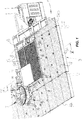
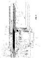
- numeral 1 designates the base of a punching machine.
- the base 1 comprises a support frame 2, that supports a work table 3 on which items in sheet form 5 to be punched have to be laid and displaced.
- the displacement of sheet items 5 occurs by means of a moving gripper device 3c in the work table 3, which is designed to grasp and release the sheet items 50 and place them under the punching devices.
- a horizontal support surface 4 is defined in the work table 2 and has a die therein accommodating a series of counter-punches 6 that cooperate with corresponding punches held within an operating head 7, as is typically provided in a punching machine.
- Both the punches and the counter punches may be arranged within respective housing devices, known as punch holders, which contain a predetermined number thereof, each being automatically selectable as needed.
- the punches, the punch holders and the dies form together the above mentioned punching devices.
- An opening 8 is formed in the work table 3, for receiving a movable section 9 that can move in two directions of movement, namely a direction of translation coplanar with the work table 3 and a direction of inclination to the latter, as better described below.
- the opening 8 has a quadrangular perimeter and the movable section 9 also has a quadrangular perimeter, such that the perimeter sides of both are mutually parallel.
- Figure 3 shows that one of the sides of the movable section 9, namely the side that is considered as the front side, as it is parallel to the front edge 3a of the work table 3 and designated by numeral 10, has a recess 10a, whose purpose will be described below.
- the movable section 9 is mounted to slide guide means 11 and is slidably driven between a punch position and a discharge position, for discharging the punched workpieces having a restricted size, the term restricted size being intended to designate a size of the order of 200 x 200 mm or less.
- the movable section 9 is driven for horizontal displacement by a fluid-dynamic actuator unit 12 which is interposed between one rear side 13 of the movable section 9, opposite to the front side 10, and the frame 2.
- the movable section 9, for discharging formed and punched workpieces having a large size, i.e. larger than that the above mentioned size, is also adapted to be inclined in a direction of inclination, as shown in Figures 2 , 6 , 7 , by pivoting about hinges (or guides) 14, with parallel and coaxial axes of rotation, oriented perpendicular to the front 10 and rear 13 sides of the movable section 9.
- the direction of inclination of the movable section 9 allows the latter to pivot toward the underlying part of the work table 3 to discharge the large punched and formed workpieces onto an evacuation conveyor 15 which is arranged in the base 1 for this purpose.
- the inclination movement of the movable section 9 is obtained using an actuator unit, not shown but known to the skilled person.
- a chute 16 is also shown below the work table 3, in vertically aligned relationship to the recess 10a, for conveying punched and formed workpieces having a small size, toward a collection container located at the discharge edge of the chute 16 and adapted to be removed for cyclic discharge.
- the length of the movable section 9 between the two front 10 and rear 13 sides is smaller than the corresponding length of the opening 8, to allow the movable section 9 to move therein between a punch position and a discharge position.
- the movable section 9 is shown in the punch position, in which it extends the support surface 4 in substantially seamless fashion, whereas in Figures 3 and 4 the movable section 9 is shown in a displaced position toward the rear portion of the opening 8, i.e. the rear edge 3b of the work table 3, and opens a passage 18 through which the small punched and formed workpieces may fall and be conveyed from the chute 16 into the collection container 17.
- the movable section 9 consists of a plurality of rollers 19, powered by a motor unit 20, which are supported in parallel relationship, between the front side 10 and the rear side 13, thereby forming a movable surface 9a which, when the movable section 9 is in the punch position or in a small-workpiece discharge position, is substantially coplanar with the support surface 4 of the work table 3.
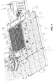
- Handling of particularly large workpieces 5, as shown in Figure 8 may be also ensured, in a second embodiment of the invention, by also forming the end portion of the support surface 4 by additional rollers 19', identical to those that are part of the movable section 9.
- rollers 19' are rotatably driven by a motor unit 20' and form, with the rollers 19 of the movable section 9, a moving carpet, allowing particularly long workpieces to slide thereon toward a lateral discharge edge 3c of the work table 3.
- the movable section 9 has three operating positions overall, i.e. a punch position, in which it is entirely displaced toward the front edge 3a of the work table 3, a large-workpiece discharge position, in which it still remains in the punch position, but is pivoted toward a lower portion of the work table 3, and a small-workpiece discharge position, in which it is coplanar with the support surface 4, but retracted toward the rear side 13, thereby forming the passage 18.
- the selection of the work positions of the movable section 9 is automatically made by the electronic program of a computer that controls the operation of the punching machine according to the working cycle that has been set, to obtain small- or large-sized punched and formed workpieces.
- the movable section 9 is held in the normal punching position, i.e. coplanar with the support surface 4 of the work table 3 during completion of the punching steps and then, each time a punching cycle is completed, it is rotated toward the underlying portion of the work table 3 to discharge the large-sized punched and formed workpieces onto the conveyor 15.
- the discharge step is facilitated by rotating the powered rollers 19 that turn the support surface of the movable section 9 into a moving carpet.
- the rollers 19 In order to reduce friction with the punched workpieces to be discharged, the rollers 19 have radial and flexible bristles on their respective outer surfaces, to provide a point-like contact between the latter and the lower surface of each punched workpiece.
- the work table 3 When dealing with very large punched and formed workpieces, e.g. having a size of 1,000 x 3,000 mm, the work table 3 consists of a substantially seamless succession of the rollers 19' that form a substantially continuous moving carpet and the rollers 19 of the movable section 9, the latter being powered to provide a motorized carpet for moving these very large workpieces toward the lateral discharge edge 3c.
- the movable section 9 is caused to slide to a programmed extent toward the rear edge 3b of the work table 3, thereby creating the passage 18.
- This passage which is considerably wider at the recess 10a of the front side 10, is used to drop the small workpieces onto the underlying chute 16, that conveys them into the collection container 17.
- the invention was found to fulfill the intended objects.
Landscapes
- Engineering & Computer Science (AREA)
- Mechanical Engineering (AREA)
- Perforating, Stamping-Out Or Severing By Means Other Than Cutting (AREA)
- Punching Or Piercing (AREA)
- Press Drives And Press Lines (AREA)
Claims (11)
- Stanzmaschine, die umfasst:- eine Basis (1), die einen Arbeitstisch (3) aufweist, der eine horizontale Auflagefläche (4) definiert, auf der ein zu stanzender Artikel (5) platziert werden soll, um gestanzte Artikel zu erhalten;- einen Betriebskopf, der auf dem Arbeitstisch (3) angeordnet und mit Stanzmitteln zum Stanzen des Artikels ausgestattet ist;wobei der Arbeitstisch (3) mindestens eine Öffnung (8) mit einem Umkreis umfasst, an dessen Innenseite ein beweglicher Abschnitt (9) des Arbeitstisches (3) eingesetzt ist, der eine ergänzende bewegliche Oberfläche (9a) der Auflagefläche (4) definiert und der durch Bewegungsmittel (11, 12) zwischen einer Stanzposition und einer Herunterladeposition der gestanzten Artikel bewegt werden kann, dadurch gekennzeichnet, dass der bewegliche Abschnitt (9) Bewegungsmittel (11, 12) in einer koplanaren Ausbildung mit dem Arbeitstisch (3) aufweist.
- Stanzmaschine nach Anspruch 1, wobei der bewegliche Abschnitt (9) Neigungsmittel (14) in eine Neigungsrichtung um eine Drehachse in Bezug auf den Arbeitstisch (3) umfasst.
- Stanzmaschine nach Anspruch 1 oder 2, wobei der bewegliche Abschnitt (9) mindestens eine Dimension aufweist, die kleiner ist als eine entsprechende Dimension der Öffnung (8), um so einen Herunterladedurchlass (18) zwischen der Auflagefläche (4) des Arbeitstisches (3) und einer unteren Zone des letztgenannten in der Herunterladeposition zu definieren.
- Stanzmaschine nach einem der vorstehenden Ansprüche, wobei der bewegliche Abschnitt (9) eine Vielzahl von parallelen Walzenmitteln (19) umfasst, die Drehachsen parallel zur Auflagefläche (4) des Arbeitstisches (3) aufweisen und die bewegliche Oberfläche (9a) definieren.
- Stanzmaschine nach Anspruch 4, wobei die Walzenmittel eine Vielzahl von sich auf- und abwärts bewegender Walzen (19) umfassen und durch Antriebsmittel (20) in Drehung versetzt werden, wobei die Walzen (19) an ihren Außenflächen mit nach außen ragenden, flexiblen Borsten ausgestattet sind, die die bewegliche Oberfläche (9a) definieren.
- Stanzmaschine nach Anspruch 3, wobei in der unteren Zone Sammel- und Transportmittel (15, 17) fern der Basis (1) untergebracht sind.
- Stanzmaschine nach Anspruch 1, wobei der Umkreis viereckig ist und eine Vorderseite, die dem Betriebskopf zugewandt ist und eine gegenüberliegende Rückseite aufweist.
- Stanzmaschine nach einem der Ansprüche 1 und 6, wobei der bewegliche Abschnitt (9) eine viereckige Plattform umfasst, mit Seiten, die zu den Seiten des viereckigen Umkreises parallel sind, und die in der Innenseite des letztgenannten enthalten ist, die abwechselnd zwischen der Stanzposition und der Herunterladeposition beweglich ist.
- Stanzmaschine nach einem der vorstehenden Ansprüche, wobei eine Vorderseite (10) des beweglichen Abschnitts (9) eine hindurchgehende Vertiefung (10a) für gestanzte Artikel aufweist.
- Stanzmaschine nach Anspruch 10, wobei die Bewegungsmittel umfassen:- horizontale Führungsmittel (11), an welchen Gleitmittel, die an dem beweglichen Abschnitt (9) fixiert sind, gleitfähig angeordnet sind, und- Betätigungsmittel (12), die zwischen der Basis (1) und dem beweglichen Abschnitt (9) eingesetzt sind.
- Stanzmaschine nach einem der vorstehenden Ansprüche, wobei unter dem Arbeitstisch (3) eine Kanalisierungsrutsche (16) der gestanzten Artikel zu den Sammel- und Transportmitteln (15, 17) angeordnet ist.
Applications Claiming Priority (2)
| Application Number | Priority Date | Filing Date | Title |
|---|---|---|---|
| IT000256A ITMO20120256A1 (it) | 2012-10-22 | 2012-10-22 | Macchina punzonatrice |
| PCT/IB2013/059529 WO2014064604A1 (en) | 2012-10-22 | 2013-10-22 | Punching machine |
Publications (2)
| Publication Number | Publication Date |
|---|---|
| EP2916974A1 EP2916974A1 (de) | 2015-09-16 |
| EP2916974B1 true EP2916974B1 (de) | 2019-10-30 |
Family
ID=47471925
Family Applications (1)
| Application Number | Title | Priority Date | Filing Date |
|---|---|---|---|
| EP13818405.6A Active EP2916974B1 (de) | 2012-10-22 | 2013-10-22 | Stanzmaschine |
Country Status (5)
| Country | Link |
|---|---|
| EP (1) | EP2916974B1 (de) |
| CN (1) | CN105050746B (de) |
| IT (1) | ITMO20120256A1 (de) |
| RU (1) | RU2015119150A (de) |
| WO (1) | WO2014064604A1 (de) |
Families Citing this family (1)
| Publication number | Priority date | Publication date | Assignee | Title |
|---|---|---|---|---|
| CN119427716B (zh) * | 2025-01-08 | 2026-04-10 | 江苏玉河教玩具有限公司 | 一种塑料玩具生产用冲床设备及其方法 |
Family Cites Families (8)
| Publication number | Priority date | Publication date | Assignee | Title |
|---|---|---|---|---|
| US4690021A (en) * | 1977-07-15 | 1987-09-01 | Strippit/Di-Acro-Houdaille, Inc. | Automatic load unload turret punch |
| US4889968A (en) * | 1987-04-30 | 1989-12-26 | Amada Company, Limited | Laser-punch composite processing machine |
| JPH0871672A (ja) * | 1994-09-06 | 1996-03-19 | Amada Co Ltd | パンチングプレス機のシュータテーブル傾動装置およびその装置を用いた傾動方法 |
| JP3442590B2 (ja) * | 1995-11-20 | 2003-09-02 | 株式会社アマダ | パンチング加工機およびその加工方法 |
| JPH1019877A (ja) * | 1996-06-27 | 1998-01-23 | Sumitomo Metal Ind Ltd | 鋼帯の連続処理ラインにおけるサンプル板の採取方法 |
| JPH10118879A (ja) * | 1996-10-21 | 1998-05-12 | Amada Co Ltd | テ−ブルシュ−タ−装置 |
| ATE507910T1 (de) * | 2007-06-30 | 2011-05-15 | Trumpf Werkzeugmaschinen Gmbh | Werkzeugmaschine und verfahren zum verbringen eines werkstückteils aus einer auflageposition in eine abfuhrposition |
| EP2359952B1 (de) * | 2010-07-09 | 2012-09-12 | TRUMPF Werkzeugmaschinen GmbH + Co. KG | Vorrichtung und Verfahren zum Ausschleusen von verschiedenen Bearbeitungsprodukten an einer Werkzeugmaschine |
-
2012
- 2012-10-22 IT IT000256A patent/ITMO20120256A1/it unknown
-
2013
- 2013-10-22 WO PCT/IB2013/059529 patent/WO2014064604A1/en not_active Ceased
- 2013-10-22 EP EP13818405.6A patent/EP2916974B1/de active Active
- 2013-10-22 RU RU2015119150A patent/RU2015119150A/ru not_active Application Discontinuation
- 2013-10-22 CN CN201380065252.6A patent/CN105050746B/zh not_active Expired - Fee Related
Non-Patent Citations (1)
| Title |
|---|
| None * |
Also Published As
| Publication number | Publication date |
|---|---|
| CN105050746B (zh) | 2017-03-15 |
| RU2015119150A (ru) | 2016-12-10 |
| CN105050746A (zh) | 2015-11-11 |
| WO2014064604A1 (en) | 2014-05-01 |
| ITMO20120256A1 (it) | 2014-04-23 |
| EP2916974A1 (de) | 2015-09-16 |
Similar Documents
| Publication | Publication Date | Title |
|---|---|---|
| KR101759843B1 (ko) | 레이저 가공기 자동화 시스템 | |
| JP6556098B2 (ja) | 工作機械及びワークパーツを排出する方法 | |
| US9028198B2 (en) | Workpiece handling systems and related devices and methods | |
| EP3819092A1 (de) | Verfahren zum entpacken eines werkstücks, entpackungsvorrichtung und eine bearbeitungsvorrichtung mit einer solchen | |
| KR100805282B1 (ko) | 금형 이동식 프레스의 절단품 자동 분류 수집 장치 및 그제어방법 | |
| CN113056423A (zh) | 用于准备由塑料制成的容器以便容器使用的设备 | |
| CN112372314B (zh) | 一种粘弹棒形材料的全自动加工装置 | |
| CN117124396A (zh) | 一种瓦楞纸板模切设备 | |
| KR20210103323A (ko) | 프레스와 저항용접기를 포함하는 통합형 자동 가공 시스템 | |
| EP2916974B1 (de) | Stanzmaschine | |
| CN210586631U (zh) | 一种自动转塔冲裁机 | |
| CN109789475B (zh) | 用于加工板状工件,特别是板材的方法和机床 | |
| CN113182740B (zh) | 双通接头内置焊片组装设备 | |
| CN214921453U (zh) | 钢板冲击试样加工生产线 | |
| KR101822956B1 (ko) | 배추 절단장치 | |
| KR840006156A (ko) | 조합된 전단 및 펀치 프레스 | |
| CN109534033B (zh) | 用于拾取坯料样品的装置、用于修整片材形元件的机器以及拾取坯料的方法 | |
| WO2015112345A1 (en) | Side loading pendulum slicer | |
| CN108926012A (zh) | 一种芒果去皮整机结构 | |
| KR101844532B1 (ko) | 절단가공시스템 | |
| CN213443490U (zh) | 一种垛料切膜设备 | |
| CN210233264U (zh) | 一种热固板切割线 | |
| CN212794301U (zh) | 一种钣金件孔位去毛刺设备 | |
| KR20190003007A (ko) | 자동차 블로워 성형제품의 가공장치 | |
| CN115673775A (zh) | 一种铜包边过滤网全自动生产装置及其加工方法 |
Legal Events
| Date | Code | Title | Description |
|---|---|---|---|
| PUAI | Public reference made under article 153(3) epc to a published international application that has entered the european phase |
Free format text: ORIGINAL CODE: 0009012 |
|
| 17P | Request for examination filed |
Effective date: 20150521 |
|
| AK | Designated contracting states |
Kind code of ref document: A1 Designated state(s): AL AT BE BG CH CY CZ DE DK EE ES FI FR GB GR HR HU IE IS IT LI LT LU LV MC MK MT NL NO PL PT RO RS SE SI SK SM TR |
|
| AX | Request for extension of the european patent |
Extension state: BA ME |
|
| DAX | Request for extension of the european patent (deleted) | ||
| GRAP | Despatch of communication of intention to grant a patent |
Free format text: ORIGINAL CODE: EPIDOSNIGR1 |
|
| STAA | Information on the status of an ep patent application or granted ep patent |
Free format text: STATUS: GRANT OF PATENT IS INTENDED |
|
| INTG | Intention to grant announced |
Effective date: 20190521 |
|
| GRAS | Grant fee paid |
Free format text: ORIGINAL CODE: EPIDOSNIGR3 |
|
| GRAA | (expected) grant |
Free format text: ORIGINAL CODE: 0009210 |
|
| STAA | Information on the status of an ep patent application or granted ep patent |
Free format text: STATUS: THE PATENT HAS BEEN GRANTED |
|
| AK | Designated contracting states |
Kind code of ref document: B1 Designated state(s): AL AT BE BG CH CY CZ DE DK EE ES FI FR GB GR HR HU IE IS IT LI LT LU LV MC MK MT NL NO PL PT RO RS SE SI SK SM TR |
|
| REG | Reference to a national code |
Ref country code: GB Ref legal event code: FG4D |
|
| REG | Reference to a national code |
Ref country code: CH Ref legal event code: EP |
|
| REG | Reference to a national code |
Ref country code: AT Ref legal event code: REF Ref document number: 1195583 Country of ref document: AT Kind code of ref document: T Effective date: 20191115 |
|
| REG | Reference to a national code |
Ref country code: DE Ref legal event code: R096 Ref document number: 602013062309 Country of ref document: DE |
|
| REG | Reference to a national code |
Ref country code: IE Ref legal event code: FG4D |
|
| REG | Reference to a national code |
Ref country code: LT Ref legal event code: MG4D |
|
| PG25 | Lapsed in a contracting state [announced via postgrant information from national office to epo] |
Ref country code: BG Free format text: LAPSE BECAUSE OF FAILURE TO SUBMIT A TRANSLATION OF THE DESCRIPTION OR TO PAY THE FEE WITHIN THE PRESCRIBED TIME-LIMIT Effective date: 20200130 Ref country code: GR Free format text: LAPSE BECAUSE OF FAILURE TO SUBMIT A TRANSLATION OF THE DESCRIPTION OR TO PAY THE FEE WITHIN THE PRESCRIBED TIME-LIMIT Effective date: 20200131 Ref country code: LT Free format text: LAPSE BECAUSE OF FAILURE TO SUBMIT A TRANSLATION OF THE DESCRIPTION OR TO PAY THE FEE WITHIN THE PRESCRIBED TIME-LIMIT Effective date: 20191030 Ref country code: FI Free format text: LAPSE BECAUSE OF FAILURE TO SUBMIT A TRANSLATION OF THE DESCRIPTION OR TO PAY THE FEE WITHIN THE PRESCRIBED TIME-LIMIT Effective date: 20191030 Ref country code: LV Free format text: LAPSE BECAUSE OF FAILURE TO SUBMIT A TRANSLATION OF THE DESCRIPTION OR TO PAY THE FEE WITHIN THE PRESCRIBED TIME-LIMIT Effective date: 20191030 Ref country code: SE Free format text: LAPSE BECAUSE OF FAILURE TO SUBMIT A TRANSLATION OF THE DESCRIPTION OR TO PAY THE FEE WITHIN THE PRESCRIBED TIME-LIMIT Effective date: 20191030 Ref country code: PL Free format text: LAPSE BECAUSE OF FAILURE TO SUBMIT A TRANSLATION OF THE DESCRIPTION OR TO PAY THE FEE WITHIN THE PRESCRIBED TIME-LIMIT Effective date: 20191030 Ref country code: NO Free format text: LAPSE BECAUSE OF FAILURE TO SUBMIT A TRANSLATION OF THE DESCRIPTION OR TO PAY THE FEE WITHIN THE PRESCRIBED TIME-LIMIT Effective date: 20200130 Ref country code: ES Free format text: LAPSE BECAUSE OF FAILURE TO SUBMIT A TRANSLATION OF THE DESCRIPTION OR TO PAY THE FEE WITHIN THE PRESCRIBED TIME-LIMIT Effective date: 20191030 Ref country code: NL Free format text: LAPSE BECAUSE OF FAILURE TO SUBMIT A TRANSLATION OF THE DESCRIPTION OR TO PAY THE FEE WITHIN THE PRESCRIBED TIME-LIMIT Effective date: 20191030 Ref country code: PT Free format text: LAPSE BECAUSE OF FAILURE TO SUBMIT A TRANSLATION OF THE DESCRIPTION OR TO PAY THE FEE WITHIN THE PRESCRIBED TIME-LIMIT Effective date: 20200302 |
|
| REG | Reference to a national code |
Ref country code: NL Ref legal event code: MP Effective date: 20191030 |
|
| PG25 | Lapsed in a contracting state [announced via postgrant information from national office to epo] |
Ref country code: IS Free format text: LAPSE BECAUSE OF FAILURE TO SUBMIT A TRANSLATION OF THE DESCRIPTION OR TO PAY THE FEE WITHIN THE PRESCRIBED TIME-LIMIT Effective date: 20200229 Ref country code: HR Free format text: LAPSE BECAUSE OF FAILURE TO SUBMIT A TRANSLATION OF THE DESCRIPTION OR TO PAY THE FEE WITHIN THE PRESCRIBED TIME-LIMIT Effective date: 20191030 Ref country code: RS Free format text: LAPSE BECAUSE OF FAILURE TO SUBMIT A TRANSLATION OF THE DESCRIPTION OR TO PAY THE FEE WITHIN THE PRESCRIBED TIME-LIMIT Effective date: 20191030 |
|
| PG25 | Lapsed in a contracting state [announced via postgrant information from national office to epo] |
Ref country code: AL Free format text: LAPSE BECAUSE OF FAILURE TO SUBMIT A TRANSLATION OF THE DESCRIPTION OR TO PAY THE FEE WITHIN THE PRESCRIBED TIME-LIMIT Effective date: 20191030 |
|
| PG25 | Lapsed in a contracting state [announced via postgrant information from national office to epo] |
Ref country code: EE Free format text: LAPSE BECAUSE OF FAILURE TO SUBMIT A TRANSLATION OF THE DESCRIPTION OR TO PAY THE FEE WITHIN THE PRESCRIBED TIME-LIMIT Effective date: 20191030 Ref country code: DK Free format text: LAPSE BECAUSE OF FAILURE TO SUBMIT A TRANSLATION OF THE DESCRIPTION OR TO PAY THE FEE WITHIN THE PRESCRIBED TIME-LIMIT Effective date: 20191030 Ref country code: RO Free format text: LAPSE BECAUSE OF FAILURE TO SUBMIT A TRANSLATION OF THE DESCRIPTION OR TO PAY THE FEE WITHIN THE PRESCRIBED TIME-LIMIT Effective date: 20191030 Ref country code: CZ Free format text: LAPSE BECAUSE OF FAILURE TO SUBMIT A TRANSLATION OF THE DESCRIPTION OR TO PAY THE FEE WITHIN THE PRESCRIBED TIME-LIMIT Effective date: 20191030 |
|
| REG | Reference to a national code |
Ref country code: DE Ref legal event code: R097 Ref document number: 602013062309 Country of ref document: DE |
|
| REG | Reference to a national code |
Ref country code: AT Ref legal event code: MK05 Ref document number: 1195583 Country of ref document: AT Kind code of ref document: T Effective date: 20191030 |
|
| PG25 | Lapsed in a contracting state [announced via postgrant information from national office to epo] |
Ref country code: SM Free format text: LAPSE BECAUSE OF FAILURE TO SUBMIT A TRANSLATION OF THE DESCRIPTION OR TO PAY THE FEE WITHIN THE PRESCRIBED TIME-LIMIT Effective date: 20191030 Ref country code: SK Free format text: LAPSE BECAUSE OF FAILURE TO SUBMIT A TRANSLATION OF THE DESCRIPTION OR TO PAY THE FEE WITHIN THE PRESCRIBED TIME-LIMIT Effective date: 20191030 |
|
| PLBE | No opposition filed within time limit |
Free format text: ORIGINAL CODE: 0009261 |
|
| STAA | Information on the status of an ep patent application or granted ep patent |
Free format text: STATUS: NO OPPOSITION FILED WITHIN TIME LIMIT |
|
| 26N | No opposition filed |
Effective date: 20200731 |
|
| PG25 | Lapsed in a contracting state [announced via postgrant information from national office to epo] |
Ref country code: AT Free format text: LAPSE BECAUSE OF FAILURE TO SUBMIT A TRANSLATION OF THE DESCRIPTION OR TO PAY THE FEE WITHIN THE PRESCRIBED TIME-LIMIT Effective date: 20191030 Ref country code: SI Free format text: LAPSE BECAUSE OF FAILURE TO SUBMIT A TRANSLATION OF THE DESCRIPTION OR TO PAY THE FEE WITHIN THE PRESCRIBED TIME-LIMIT Effective date: 20191030 |
|
| REG | Reference to a national code |
Ref country code: CH Ref legal event code: PL |
|
| GBPC | Gb: european patent ceased through non-payment of renewal fee |
Effective date: 20201022 |
|
| PG25 | Lapsed in a contracting state [announced via postgrant information from national office to epo] |
Ref country code: MC Free format text: LAPSE BECAUSE OF FAILURE TO SUBMIT A TRANSLATION OF THE DESCRIPTION OR TO PAY THE FEE WITHIN THE PRESCRIBED TIME-LIMIT Effective date: 20191030 Ref country code: LU Free format text: LAPSE BECAUSE OF NON-PAYMENT OF DUE FEES Effective date: 20201022 |
|
| REG | Reference to a national code |
Ref country code: BE Ref legal event code: MM Effective date: 20201031 |
|
| PG25 | Lapsed in a contracting state [announced via postgrant information from national office to epo] |
Ref country code: FR Free format text: LAPSE BECAUSE OF NON-PAYMENT OF DUE FEES Effective date: 20201031 |
|
| PG25 | Lapsed in a contracting state [announced via postgrant information from national office to epo] |
Ref country code: GB Free format text: LAPSE BECAUSE OF NON-PAYMENT OF DUE FEES Effective date: 20201022 Ref country code: LI Free format text: LAPSE BECAUSE OF NON-PAYMENT OF DUE FEES Effective date: 20201031 Ref country code: CH Free format text: LAPSE BECAUSE OF NON-PAYMENT OF DUE FEES Effective date: 20201031 Ref country code: BE Free format text: LAPSE BECAUSE OF NON-PAYMENT OF DUE FEES Effective date: 20201031 |
|
| PG25 | Lapsed in a contracting state [announced via postgrant information from national office to epo] |
Ref country code: IE Free format text: LAPSE BECAUSE OF NON-PAYMENT OF DUE FEES Effective date: 20201022 |
|
| PGFP | Annual fee paid to national office [announced via postgrant information from national office to epo] |
Ref country code: IT Payment date: 20210721 Year of fee payment: 9 |
|
| PGFP | Annual fee paid to national office [announced via postgrant information from national office to epo] |
Ref country code: DE Payment date: 20211007 Year of fee payment: 9 |
|
| PG25 | Lapsed in a contracting state [announced via postgrant information from national office to epo] |
Ref country code: TR Free format text: LAPSE BECAUSE OF FAILURE TO SUBMIT A TRANSLATION OF THE DESCRIPTION OR TO PAY THE FEE WITHIN THE PRESCRIBED TIME-LIMIT Effective date: 20191030 Ref country code: MT Free format text: LAPSE BECAUSE OF FAILURE TO SUBMIT A TRANSLATION OF THE DESCRIPTION OR TO PAY THE FEE WITHIN THE PRESCRIBED TIME-LIMIT Effective date: 20191030 Ref country code: CY Free format text: LAPSE BECAUSE OF FAILURE TO SUBMIT A TRANSLATION OF THE DESCRIPTION OR TO PAY THE FEE WITHIN THE PRESCRIBED TIME-LIMIT Effective date: 20191030 |
|
| PG25 | Lapsed in a contracting state [announced via postgrant information from national office to epo] |
Ref country code: MK Free format text: LAPSE BECAUSE OF FAILURE TO SUBMIT A TRANSLATION OF THE DESCRIPTION OR TO PAY THE FEE WITHIN THE PRESCRIBED TIME-LIMIT Effective date: 20191030 |
|
| REG | Reference to a national code |
Ref country code: DE Ref legal event code: R119 Ref document number: 602013062309 Country of ref document: DE |
|
| PG25 | Lapsed in a contracting state [announced via postgrant information from national office to epo] |
Ref country code: DE Free format text: LAPSE BECAUSE OF NON-PAYMENT OF DUE FEES Effective date: 20230503 |
|
| PG25 | Lapsed in a contracting state [announced via postgrant information from national office to epo] |
Ref country code: IT Free format text: LAPSE BECAUSE OF NON-PAYMENT OF DUE FEES Effective date: 20221022 |