EP2916890B1 - Dose setting mechanism for a drug delivery device - Google Patents
Dose setting mechanism for a drug delivery device Download PDFInfo
- Publication number
- EP2916890B1 EP2916890B1 EP13786265.2A EP13786265A EP2916890B1 EP 2916890 B1 EP2916890 B1 EP 2916890B1 EP 13786265 A EP13786265 A EP 13786265A EP 2916890 B1 EP2916890 B1 EP 2916890B1
- Authority
- EP
- European Patent Office
- Prior art keywords
- sleeve
- ratchet
- dose setting
- intermediate element
- setting mechanism
- Prior art date
- Legal status (The legal status is an assumption and is not a legal conclusion. Google has not performed a legal analysis and makes no representation as to the accuracy of the status listed.)
- Active
Links
- 230000007246 mechanism Effects 0.000 title claims description 44
- 238000012377 drug delivery Methods 0.000 title claims description 20
- 230000005284 excitation Effects 0.000 claims description 12
- 239000003814 drug Substances 0.000 claims description 9
- 238000000465 moulding Methods 0.000 claims description 7
- 238000013016 damping Methods 0.000 claims description 6
- 239000000463 material Substances 0.000 claims description 5
- 229920002725 thermoplastic elastomer Polymers 0.000 claims description 5
- JUFFVKRROAPVBI-PVOYSMBESA-N chembl1210015 Chemical compound C([C@@H](C(=O)N[C@@H]([C@@H](C)CC)C(=O)N[C@@H](CCC(O)=O)C(=O)N[C@@H](CC=1C2=CC=CC=C2NC=1)C(=O)N[C@@H](CC(C)C)C(=O)N[C@@H](CCCCN)C(=O)N[C@@H](CC(=O)N[C@H]1[C@@H]([C@@H](O)[C@H](O[C@H]2[C@@H]([C@@H](O)[C@@H](O)[C@@H](CO[C@]3(O[C@@H](C[C@H](O)[C@H](O)CO)[C@H](NC(C)=O)[C@@H](O)C3)C(O)=O)O2)O)[C@@H](CO)O1)NC(C)=O)C(=O)NCC(=O)NCC(=O)N1[C@@H](CCC1)C(=O)N[C@@H](CO)C(=O)N[C@@H](CO)C(=O)NCC(=O)N[C@@H](C)C(=O)N1[C@@H](CCC1)C(=O)N1[C@@H](CCC1)C(=O)N1[C@@H](CCC1)C(=O)N[C@@H](CO)C(N)=O)NC(=O)[C@H](CC(C)C)NC(=O)[C@H](CCCNC(N)=N)NC(=O)[C@@H](NC(=O)[C@H](C)NC(=O)[C@H](CCC(O)=O)NC(=O)[C@H](CCC(O)=O)NC(=O)[C@H](CCC(O)=O)NC(=O)[C@H](CCSC)NC(=O)[C@H](CCC(N)=O)NC(=O)[C@H](CCCCN)NC(=O)[C@H](CO)NC(=O)[C@H](CC(C)C)NC(=O)[C@H](CC(O)=O)NC(=O)[C@H](CO)NC(=O)[C@@H](NC(=O)[C@H](CC=1C=CC=CC=1)NC(=O)[C@@H](NC(=O)CNC(=O)[C@H](CCC(O)=O)NC(=O)CNC(=O)[C@@H](N)CC=1NC=NC=1)[C@@H](C)O)[C@@H](C)O)C(C)C)C1=CC=CC=C1 JUFFVKRROAPVBI-PVOYSMBESA-N 0.000 description 54
- 108010011459 Exenatide Proteins 0.000 description 50
- 229960001519 exenatide Drugs 0.000 description 50
- 101000976075 Homo sapiens Insulin Proteins 0.000 description 22
- QEFRNWWLZKMPFJ-YGVKFDHGSA-N L-methionine S-oxide Chemical compound CS(=O)CC[C@H](N)C(O)=O QEFRNWWLZKMPFJ-YGVKFDHGSA-N 0.000 description 22
- PBGKTOXHQIOBKM-FHFVDXKLSA-N insulin (human) Chemical compound C([C@@H](C(=O)N[C@@H](CC(C)C)C(=O)N[C@H]1CSSC[C@H]2C(=O)N[C@H](C(=O)N[C@@H](CO)C(=O)N[C@H](C(=O)N[C@H](C(N[C@@H](CO)C(=O)N[C@@H](CC(C)C)C(=O)N[C@@H](CC=3C=CC(O)=CC=3)C(=O)N[C@@H](CCC(N)=O)C(=O)N[C@@H](CC(C)C)C(=O)N[C@@H](CCC(O)=O)C(=O)N[C@@H](CC(N)=O)C(=O)N[C@@H](CC=3C=CC(O)=CC=3)C(=O)N[C@@H](CSSC[C@H](NC(=O)[C@H](C(C)C)NC(=O)[C@H](CC(C)C)NC(=O)[C@H](CC=3C=CC(O)=CC=3)NC(=O)[C@H](CC(C)C)NC(=O)[C@H](C)NC(=O)[C@H](CCC(O)=O)NC(=O)[C@H](C(C)C)NC(=O)[C@H](CC(C)C)NC(=O)[C@H](CC=3NC=NC=3)NC(=O)[C@H](CO)NC(=O)CNC1=O)C(=O)NCC(=O)N[C@@H](CCC(O)=O)C(=O)N[C@@H](CCCNC(N)=N)C(=O)NCC(=O)N[C@@H](CC=1C=CC=CC=1)C(=O)N[C@@H](CC=1C=CC=CC=1)C(=O)N[C@@H](CC=1C=CC(O)=CC=1)C(=O)N[C@@H]([C@@H](C)O)C(=O)N1[C@@H](CCC1)C(=O)N[C@@H](CCCCN)C(=O)N[C@@H]([C@@H](C)O)C(O)=O)C(=O)N[C@@H](CC(N)=O)C(O)=O)=O)CSSC[C@@H](C(N2)=O)NC(=O)[C@H](CCC(N)=O)NC(=O)[C@H](CCC(O)=O)NC(=O)[C@H](C(C)C)NC(=O)[C@@H](NC(=O)CN)[C@@H](C)CC)[C@@H](C)CC)[C@@H](C)O)NC(=O)[C@H](CCC(N)=O)NC(=O)[C@H](CC(N)=O)NC(=O)[C@@H](NC(=O)[C@@H](N)CC=1C=CC=CC=1)C(C)C)C1=CN=CN1 PBGKTOXHQIOBKM-FHFVDXKLSA-N 0.000 description 21
- 239000012634 fragment Substances 0.000 description 10
- 235000001014 amino acid Nutrition 0.000 description 9
- 150000001413 amino acids Chemical class 0.000 description 9
- 150000001875 compounds Chemical class 0.000 description 8
- 150000003839 salts Chemical class 0.000 description 8
- 239000000427 antigen Substances 0.000 description 7
- 102000036639 antigens Human genes 0.000 description 7
- 108091007433 antigens Proteins 0.000 description 7
- 230000008878 coupling Effects 0.000 description 5
- 238000010168 coupling process Methods 0.000 description 5
- 238000005859 coupling reaction Methods 0.000 description 5
- 206010012601 diabetes mellitus Diseases 0.000 description 5
- 238000002347 injection Methods 0.000 description 5
- 239000007924 injection Substances 0.000 description 5
- NOESYZHRGYRDHS-UHFFFAOYSA-N insulin Chemical class N1C(=O)C(NC(=O)C(CCC(N)=O)NC(=O)C(CCC(O)=O)NC(=O)C(C(C)C)NC(=O)C(NC(=O)CN)C(C)CC)CSSCC(C(NC(CO)C(=O)NC(CC(C)C)C(=O)NC(CC=2C=CC(O)=CC=2)C(=O)NC(CCC(N)=O)C(=O)NC(CC(C)C)C(=O)NC(CCC(O)=O)C(=O)NC(CC(N)=O)C(=O)NC(CC=2C=CC(O)=CC=2)C(=O)NC(CSSCC(NC(=O)C(C(C)C)NC(=O)C(CC(C)C)NC(=O)C(CC=2C=CC(O)=CC=2)NC(=O)C(CC(C)C)NC(=O)C(C)NC(=O)C(CCC(O)=O)NC(=O)C(C(C)C)NC(=O)C(CC(C)C)NC(=O)C(CC=2NC=NC=2)NC(=O)C(CO)NC(=O)CNC2=O)C(=O)NCC(=O)NC(CCC(O)=O)C(=O)NC(CCCNC(N)=N)C(=O)NCC(=O)NC(CC=3C=CC=CC=3)C(=O)NC(CC=3C=CC=CC=3)C(=O)NC(CC=3C=CC(O)=CC=3)C(=O)NC(C(C)O)C(=O)N3C(CCC3)C(=O)NC(CCCCN)C(=O)NC(C)C(O)=O)C(=O)NC(CC(N)=O)C(O)=O)=O)NC(=O)C(C(C)CC)NC(=O)C(CO)NC(=O)C(C(C)O)NC(=O)C1CSSCC2NC(=O)C(CC(C)C)NC(=O)C(NC(=O)C(CCC(N)=O)NC(=O)C(CC(N)=O)NC(=O)C(NC(=O)C(N)CC=1C=CC=CC=1)C(C)C)CC1=CN=CN1 NOESYZHRGYRDHS-UHFFFAOYSA-N 0.000 description 5
- 108090000765 processed proteins & peptides Proteins 0.000 description 5
- 108060003951 Immunoglobulin Proteins 0.000 description 4
- 102000018358 immunoglobulin Human genes 0.000 description 4
- 238000004519 manufacturing process Methods 0.000 description 4
- 108010047041 Complementarity Determining Regions Proteins 0.000 description 3
- 210000003719 b-lymphocyte Anatomy 0.000 description 3
- 230000008901 benefit Effects 0.000 description 3
- 150000004676 glycans Chemical class 0.000 description 3
- 229940088597 hormone Drugs 0.000 description 3
- 239000005556 hormone Substances 0.000 description 3
- 239000003055 low molecular weight heparin Substances 0.000 description 3
- 229940127215 low-molecular weight heparin Drugs 0.000 description 3
- 230000013011 mating Effects 0.000 description 3
- 229920001282 polysaccharide Polymers 0.000 description 3
- 239000005017 polysaccharide Substances 0.000 description 3
- 238000011282 treatment Methods 0.000 description 3
- 208000004476 Acute Coronary Syndrome Diseases 0.000 description 2
- 208000002249 Diabetes Complications Diseases 0.000 description 2
- 206010012689 Diabetic retinopathy Diseases 0.000 description 2
- 108010088406 Glucagon-Like Peptides Proteins 0.000 description 2
- 108090001061 Insulin Proteins 0.000 description 2
- 102000004877 Insulin Human genes 0.000 description 2
- 241000124008 Mammalia Species 0.000 description 2
- 238000010521 absorption reaction Methods 0.000 description 2
- 239000002253 acid Substances 0.000 description 2
- 230000009471 action Effects 0.000 description 2
- 150000001447 alkali salts Chemical class 0.000 description 2
- 125000000151 cysteine group Chemical group N[C@@H](CS)C(=O)* 0.000 description 2
- 238000013461 design Methods 0.000 description 2
- 230000029087 digestion Effects 0.000 description 2
- 208000037265 diseases, disorders, signs and symptoms Diseases 0.000 description 2
- LMHMJYMCGJNXRS-IOPUOMRJSA-N exendin-3 Chemical compound C([C@@H](C(=O)N[C@@H]([C@@H](C)CC)C(=O)N[C@@H](CCC(O)=O)C(=O)N[C@@H](CC=1C2=CC=CC=C2NC=1)C(=O)N[C@@H](CC(C)C)C(=O)N[C@@H](CCCCN)C(=O)N[C@@H](CC(N)=O)C(=O)NCC(=O)NCC(=O)N1[C@@H](CCC1)C(=O)N[C@@H](CO)C(=O)N[C@@H](CO)C(=O)NCC(=O)N[C@@H](C)C(=O)N1[C@@H](CCC1)C(=O)N1[C@@H](CCC1)C(=O)N1[C@@H](CCC1)C(=O)N[C@@H](CO)C(N)=O)NC(=O)[C@H](CC(C)C)NC(=O)[C@H](CCCNC(N)=N)NC(=O)[C@@H](NC(=O)[C@H](C)NC(=O)[C@H](CCC(O)=O)NC(=O)[C@H](CCC(O)=O)NC(=O)[C@H](CCC(O)=O)NC(=O)[C@H](CCSC)NC(=O)[C@H](CCC(N)=O)NC(=O)[C@H](CCCCN)NC(=O)[C@H](CO)NC(=O)[C@H](CC(C)C)NC(=O)[C@H](CC(O)=O)NC(=O)[C@H](CO)NC(=O)[C@@H](NC(=O)[C@H](CC=1C=CC=CC=1)NC(=O)[C@@H](NC(=O)CNC(=O)[C@H](CC(O)=O)NC(=O)[C@H](CO)NC(=O)[C@@H](N)CC=1N=CNC=1)[C@H](C)O)[C@H](C)O)C(C)C)C1=CC=CC=C1 LMHMJYMCGJNXRS-IOPUOMRJSA-N 0.000 description 2
- 229940125396 insulin Drugs 0.000 description 2
- 238000000034 method Methods 0.000 description 2
- 239000000203 mixture Substances 0.000 description 2
- 239000000178 monomer Substances 0.000 description 2
- 239000004033 plastic Substances 0.000 description 2
- 230000008569 process Effects 0.000 description 2
- 102000004196 processed proteins & peptides Human genes 0.000 description 2
- 238000011321 prophylaxis Methods 0.000 description 2
- 238000007789 sealing Methods 0.000 description 2
- 239000012453 solvate Substances 0.000 description 2
- KIUKXJAPPMFGSW-DNGZLQJQSA-N (2S,3S,4S,5R,6R)-6-[(2S,3R,4R,5S,6R)-3-Acetamido-2-[(2S,3S,4R,5R,6R)-6-[(2R,3R,4R,5S,6R)-3-acetamido-2,5-dihydroxy-6-(hydroxymethyl)oxan-4-yl]oxy-2-carboxy-4,5-dihydroxyoxan-3-yl]oxy-5-hydroxy-6-(hydroxymethyl)oxan-4-yl]oxy-3,4,5-trihydroxyoxane-2-carboxylic acid Chemical compound CC(=O)N[C@H]1[C@H](O)O[C@H](CO)[C@@H](O)[C@@H]1O[C@H]1[C@H](O)[C@@H](O)[C@H](O[C@H]2[C@@H]([C@@H](O[C@H]3[C@@H]([C@@H](O)[C@H](O)[C@H](O3)C(O)=O)O)[C@H](O)[C@@H](CO)O2)NC(C)=O)[C@@H](C(O)=O)O1 KIUKXJAPPMFGSW-DNGZLQJQSA-N 0.000 description 1
- 125000004169 (C1-C6) alkyl group Chemical group 0.000 description 1
- 125000001831 (C6-C10) heteroaryl group Chemical group 0.000 description 1
- 208000035285 Allergic Seasonal Rhinitis Diseases 0.000 description 1
- QGZKDVFQNNGYKY-UHFFFAOYSA-O Ammonium Chemical compound [NH4+] QGZKDVFQNNGYKY-UHFFFAOYSA-O 0.000 description 1
- 206010002383 Angina Pectoris Diseases 0.000 description 1
- 201000001320 Atherosclerosis Diseases 0.000 description 1
- 108010017384 Blood Proteins Proteins 0.000 description 1
- 102000004506 Blood Proteins Human genes 0.000 description 1
- 108010037003 Buserelin Proteins 0.000 description 1
- 125000000882 C2-C6 alkenyl group Chemical group 0.000 description 1
- 125000000041 C6-C10 aryl group Chemical group 0.000 description 1
- 108010000437 Deamino Arginine Vasopressin Proteins 0.000 description 1
- 208000005189 Embolism Diseases 0.000 description 1
- 108090000790 Enzymes Proteins 0.000 description 1
- 102000004190 Enzymes Human genes 0.000 description 1
- 102000012673 Follicle Stimulating Hormone Human genes 0.000 description 1
- 108010079345 Follicle Stimulating Hormone Proteins 0.000 description 1
- 102000003886 Glycoproteins Human genes 0.000 description 1
- 108090000288 Glycoproteins Proteins 0.000 description 1
- 102400000932 Gonadoliberin-1 Human genes 0.000 description 1
- 108010069236 Goserelin Proteins 0.000 description 1
- BLCLNMBMMGCOAS-URPVMXJPSA-N Goserelin Chemical compound C([C@@H](C(=O)N[C@H](COC(C)(C)C)C(=O)N[C@@H](CC(C)C)C(=O)N[C@@H](CCCN=C(N)N)C(=O)N1[C@@H](CCC1)C(=O)NNC(N)=O)NC(=O)[C@H](CO)NC(=O)[C@H](CC=1C2=CC=CC=C2NC=1)NC(=O)[C@H](CC=1NC=NC=1)NC(=O)[C@H]1NC(=O)CC1)C1=CC=C(O)C=C1 BLCLNMBMMGCOAS-URPVMXJPSA-N 0.000 description 1
- HTTJABKRGRZYRN-UHFFFAOYSA-N Heparin Chemical compound OC1C(NC(=O)C)C(O)OC(COS(O)(=O)=O)C1OC1C(OS(O)(=O)=O)C(O)C(OC2C(C(OS(O)(=O)=O)C(OC3C(C(O)C(O)C(O3)C(O)=O)OS(O)(=O)=O)C(CO)O2)NS(O)(=O)=O)C(C(O)=O)O1 HTTJABKRGRZYRN-UHFFFAOYSA-N 0.000 description 1
- 101500026183 Homo sapiens Gonadoliberin-1 Proteins 0.000 description 1
- 102000002265 Human Growth Hormone Human genes 0.000 description 1
- 108010000521 Human Growth Hormone Proteins 0.000 description 1
- 239000000854 Human Growth Hormone Substances 0.000 description 1
- 108010021625 Immunoglobulin Fragments Proteins 0.000 description 1
- 102000008394 Immunoglobulin Fragments Human genes 0.000 description 1
- 102000013463 Immunoglobulin Light Chains Human genes 0.000 description 1
- 108010065825 Immunoglobulin Light Chains Proteins 0.000 description 1
- 206010061218 Inflammation Diseases 0.000 description 1
- 108010000817 Leuprolide Proteins 0.000 description 1
- XVVOERDUTLJJHN-UHFFFAOYSA-N Lixisenatide Chemical compound C=1NC2=CC=CC=C2C=1CC(C(=O)NC(CC(C)C)C(=O)NC(CCCCN)C(=O)NC(CC(N)=O)C(=O)NCC(=O)NCC(=O)N1C(CCC1)C(=O)NC(CO)C(=O)NC(CO)C(=O)NCC(=O)NC(C)C(=O)N1C(CCC1)C(=O)N1C(CCC1)C(=O)NC(CO)C(=O)NC(CCCCN)C(=O)NC(CCCCN)C(=O)NC(CCCCN)C(=O)NC(CCCCN)C(=O)NC(CCCCN)C(=O)NC(CCCCN)C(N)=O)NC(=O)C(CCC(O)=O)NC(=O)C(C(C)CC)NC(=O)C(NC(=O)C(CC(C)C)NC(=O)C(CCCNC(N)=N)NC(=O)C(NC(=O)C(C)NC(=O)C(CCC(O)=O)NC(=O)C(CCC(O)=O)NC(=O)C(CCC(O)=O)NC(=O)C(CCSC)NC(=O)C(CCC(N)=O)NC(=O)C(CCCCN)NC(=O)C(CO)NC(=O)C(CC(C)C)NC(=O)C(CC(O)=O)NC(=O)C(CO)NC(=O)C(NC(=O)C(CC=1C=CC=CC=1)NC(=O)C(NC(=O)CNC(=O)C(CCC(O)=O)NC(=O)CNC(=O)C(N)CC=1NC=NC=1)C(C)O)C(C)O)C(C)C)CC1=CC=CC=C1 XVVOERDUTLJJHN-UHFFFAOYSA-N 0.000 description 1
- 102000009151 Luteinizing Hormone Human genes 0.000 description 1
- 108010073521 Luteinizing Hormone Proteins 0.000 description 1
- 108010021717 Nafarelin Proteins 0.000 description 1
- 206010028980 Neoplasm Diseases 0.000 description 1
- 108091034117 Oligonucleotide Proteins 0.000 description 1
- 108090000526 Papain Proteins 0.000 description 1
- 102000057297 Pepsin A Human genes 0.000 description 1
- 108090000284 Pepsin A Proteins 0.000 description 1
- ONIBWKKTOPOVIA-UHFFFAOYSA-N Proline Natural products OC(=O)C1CCCN1 ONIBWKKTOPOVIA-UHFFFAOYSA-N 0.000 description 1
- 239000004365 Protease Substances 0.000 description 1
- 208000010378 Pulmonary Embolism Diseases 0.000 description 1
- 206010043183 Teething Diseases 0.000 description 1
- 108010010056 Terlipressin Proteins 0.000 description 1
- 208000001435 Thromboembolism Diseases 0.000 description 1
- 108010050144 Triptorelin Pamoate Proteins 0.000 description 1
- 239000003513 alkali Substances 0.000 description 1
- 125000000539 amino acid group Chemical group 0.000 description 1
- 230000003321 amplification Effects 0.000 description 1
- 239000005557 antagonist Substances 0.000 description 1
- 230000004323 axial length Effects 0.000 description 1
- 230000009286 beneficial effect Effects 0.000 description 1
- 230000005540 biological transmission Effects 0.000 description 1
- 229960002719 buserelin Drugs 0.000 description 1
- CUWODFFVMXJOKD-UVLQAERKSA-N buserelin Chemical compound CCNC(=O)[C@@H]1CCCN1C(=O)[C@H](CCCN=C(N)N)NC(=O)[C@H](CC(C)C)NC(=O)[C@@H](COC(C)(C)C)NC(=O)[C@@H](NC(=O)[C@H](CO)NC(=O)[C@H](CC=1C2=CC=CC=C2NC=1)NC(=O)[C@H](CC=1NC=NC=1)NC(=O)[C@H]1NC(=O)CC1)CC1=CC=C(O)C=C1 CUWODFFVMXJOKD-UVLQAERKSA-N 0.000 description 1
- 201000011510 cancer Diseases 0.000 description 1
- 150000001720 carbohydrates Chemical class 0.000 description 1
- 235000014633 carbohydrates Nutrition 0.000 description 1
- 125000003178 carboxy group Chemical group [H]OC(*)=O 0.000 description 1
- 150000001768 cations Chemical class 0.000 description 1
- 230000000295 complement effect Effects 0.000 description 1
- 235000018417 cysteine Nutrition 0.000 description 1
- 125000003074 decanoyl group Chemical group [H]C([H])([H])C([H])([H])C([H])([H])C([H])([H])C([H])([H])C([H])([H])C([H])([H])C([H])([H])C([H])([H])C(*)=O 0.000 description 1
- 230000007423 decrease Effects 0.000 description 1
- 229960004281 desmopressin Drugs 0.000 description 1
- NFLWUMRGJYTJIN-NXBWRCJVSA-N desmopressin Chemical compound C([C@H]1C(=O)N[C@H](C(N[C@@H](CC(N)=O)C(=O)N[C@@H](CSSCCC(=O)N[C@@H](CC=2C=CC(O)=CC=2)C(=O)N1)C(=O)N1[C@@H](CCC1)C(=O)N[C@@H](CCCNC(N)=N)C(=O)NCC(N)=O)=O)CCC(=O)N)C1=CC=CC=C1 NFLWUMRGJYTJIN-NXBWRCJVSA-N 0.000 description 1
- 201000010099 disease Diseases 0.000 description 1
- 208000035475 disorder Diseases 0.000 description 1
- 238000005516 engineering process Methods 0.000 description 1
- 229960005153 enoxaparin sodium Drugs 0.000 description 1
- 229940088598 enzyme Drugs 0.000 description 1
- 108010015174 exendin 3 Proteins 0.000 description 1
- HTQBXNHDCUEHJF-URRANESESA-N exendin-4 Chemical compound C([C@@H](C(=O)N[C@@H](C(C)CC)C(=O)N[C@@H](CCC(O)=O)C(=O)N[C@@H](CC=1C2=CC=CC=C2NC=1)C(=O)N[C@@H](CC(C)C)C(=O)N[C@@H](CCCCN)C(=O)N[C@@H](CC(N)=O)C(=O)NCC(=O)NCC(=O)N1[C@@H](CCC1)C(=O)N[C@@H](CO)C(=O)N[C@@H](CO)C(=O)NCC(=O)N[C@@H](C)C(=O)N1[C@@H](CCC1)C(=O)N1[C@@H](CCC1)C(=O)N1[C@@H](CCC1)C(=O)N[C@@H](CO)C(N)=O)NC(=O)[C@H](CC(C)C)NC(=O)[C@H](CCCNC(N)=N)NC(=O)[C@@H](NC(=O)[C@H](C)NC(=O)[C@H](CCC(O)=O)NC(=O)[C@H](CCC(O)=O)NC(=O)[C@H](CCC(O)=O)NC(=O)[C@H](CCSC)NC(=O)[C@H](CCC(N)=O)NC(=O)[C@H](CCCCN)NC(=O)[C@H](CO)NC(=O)[C@H](CC(C)C)NC(=O)[C@H](CC(O)=O)NC(=O)[C@H](CO)NC(=O)[C@@H](NC(=O)[C@H](CC=1C=CC=CC=1)NC(=O)[C@@H](NC(=O)CNC(=O)[C@H](CCC(O)=O)NC(=O)CNC(=O)[C@@H](N)CC=1N=CNC=1)C(C)O)C(C)O)C(C)C)C1=CC=CC=C1 HTQBXNHDCUEHJF-URRANESESA-N 0.000 description 1
- 229960001442 gonadorelin Drugs 0.000 description 1
- XLXSAKCOAKORKW-AQJXLSMYSA-N gonadorelin Chemical compound C([C@@H](C(=O)NCC(=O)N[C@@H](CC(C)C)C(=O)N[C@@H](CCCNC(N)=N)C(=O)N1[C@@H](CCC1)C(=O)NCC(N)=O)NC(=O)[C@H](CO)NC(=O)[C@H](CC=1C2=CC=CC=C2NC=1)NC(=O)[C@H](CC=1N=CNC=1)NC(=O)[C@H]1NC(=O)CC1)C1=CC=C(O)C=C1 XLXSAKCOAKORKW-AQJXLSMYSA-N 0.000 description 1
- 229960002913 goserelin Drugs 0.000 description 1
- 229960002897 heparin Drugs 0.000 description 1
- 229920000669 heparin Polymers 0.000 description 1
- 229920002674 hyaluronan Polymers 0.000 description 1
- 229960003160 hyaluronic acid Drugs 0.000 description 1
- 150000004677 hydrates Chemical class 0.000 description 1
- 229910052739 hydrogen Inorganic materials 0.000 description 1
- 239000001257 hydrogen Substances 0.000 description 1
- 125000004435 hydrogen atom Chemical class [H]* 0.000 description 1
- 239000000960 hypophysis hormone Substances 0.000 description 1
- 210000003016 hypothalamus Anatomy 0.000 description 1
- 229940072221 immunoglobulins Drugs 0.000 description 1
- 230000004054 inflammatory process Effects 0.000 description 1
- 239000004026 insulin derivative Substances 0.000 description 1
- 230000003993 interaction Effects 0.000 description 1
- 238000011835 investigation Methods 0.000 description 1
- 230000001788 irregular Effects 0.000 description 1
- GFIJNRVAKGFPGQ-LIJARHBVSA-N leuprolide Chemical compound CCNC(=O)[C@@H]1CCCN1C(=O)[C@H](CCCNC(N)=N)NC(=O)[C@H](CC(C)C)NC(=O)[C@@H](CC(C)C)NC(=O)[C@@H](NC(=O)[C@H](CO)NC(=O)[C@H](CC=1C2=CC=CC=C2NC=1)NC(=O)[C@H](CC=1N=CNC=1)NC(=O)[C@H]1NC(=O)CC1)CC1=CC=C(O)C=C1 GFIJNRVAKGFPGQ-LIJARHBVSA-N 0.000 description 1
- 229960004338 leuprorelin Drugs 0.000 description 1
- XVVOERDUTLJJHN-IAEQDCLQSA-N lixisenatide Chemical compound C([C@@H](C(=O)N[C@@H]([C@@H](C)CC)C(=O)N[C@@H](CCC(O)=O)C(=O)N[C@@H](CC=1C2=CC=CC=C2NC=1)C(=O)N[C@@H](CC(C)C)C(=O)N[C@@H](CCCCN)C(=O)N[C@@H](CC(N)=O)C(=O)NCC(=O)NCC(=O)N1[C@@H](CCC1)C(=O)N[C@@H](CO)C(=O)N[C@@H](CO)C(=O)NCC(=O)N[C@@H](C)C(=O)N1[C@@H](CCC1)C(=O)N1[C@@H](CCC1)C(=O)N[C@@H](CO)C(=O)N[C@@H](CCCCN)C(=O)N[C@@H](CCCCN)C(=O)N[C@@H](CCCCN)C(=O)N[C@@H](CCCCN)C(=O)N[C@@H](CCCCN)C(=O)N[C@@H](CCCCN)C(N)=O)NC(=O)[C@H](CC(C)C)NC(=O)[C@H](CCCNC(N)=N)NC(=O)[C@@H](NC(=O)[C@H](C)NC(=O)[C@H](CCC(O)=O)NC(=O)[C@H](CCC(O)=O)NC(=O)[C@H](CCC(O)=O)NC(=O)[C@H](CCSC)NC(=O)[C@H](CCC(N)=O)NC(=O)[C@H](CCCCN)NC(=O)[C@H](CO)NC(=O)[C@H](CC(C)C)NC(=O)[C@H](CC(O)=O)NC(=O)[C@H](CO)NC(=O)[C@@H](NC(=O)[C@H](CC=1C=CC=CC=1)NC(=O)[C@@H](NC(=O)CNC(=O)[C@H](CCC(O)=O)NC(=O)CNC(=O)[C@@H](N)CC=1N=CNC=1)[C@@H](C)O)[C@@H](C)O)C(C)C)C1=CC=CC=C1 XVVOERDUTLJJHN-IAEQDCLQSA-N 0.000 description 1
- 108010004367 lixisenatide Proteins 0.000 description 1
- 229960001093 lixisenatide Drugs 0.000 description 1
- 208000002780 macular degeneration Diseases 0.000 description 1
- 238000007726 management method Methods 0.000 description 1
- 229940127554 medical product Drugs 0.000 description 1
- 229940126601 medicinal product Drugs 0.000 description 1
- 208000010125 myocardial infarction Diseases 0.000 description 1
- RWHUEXWOYVBUCI-ITQXDASVSA-N nafarelin Chemical compound C([C@@H](C(=O)N[C@H](CC=1C=C2C=CC=CC2=CC=1)C(=O)N[C@@H](CC(C)C)C(=O)N[C@@H](CCCN=C(N)N)C(=O)N1[C@@H](CCC1)C(=O)NCC(N)=O)NC(=O)[C@H](CO)NC(=O)[C@H](CC=1C2=CC=CC=C2NC=1)NC(=O)[C@H](CC=1NC=NC=1)NC(=O)[C@H]1NC(=O)CC1)C1=CC=C(O)C=C1 RWHUEXWOYVBUCI-ITQXDASVSA-N 0.000 description 1
- 229960002333 nafarelin Drugs 0.000 description 1
- 238000003199 nucleic acid amplification method Methods 0.000 description 1
- 230000010355 oscillation Effects 0.000 description 1
- 229940055729 papain Drugs 0.000 description 1
- 235000019834 papain Nutrition 0.000 description 1
- 229940111202 pepsin Drugs 0.000 description 1
- 239000008194 pharmaceutical composition Substances 0.000 description 1
- 229920001184 polypeptide Polymers 0.000 description 1
- 125000002924 primary amino group Chemical group [H]N([H])* 0.000 description 1
- 125000001500 prolyl group Chemical group [H]N1C([H])(C(=O)[*])C([H])([H])C([H])([H])C1([H])[H] 0.000 description 1
- 230000002797 proteolythic effect Effects 0.000 description 1
- 230000009467 reduction Effects 0.000 description 1
- 230000001105 regulatory effect Effects 0.000 description 1
- 230000000717 retained effect Effects 0.000 description 1
- 206010039073 rheumatoid arthritis Diseases 0.000 description 1
- 229960004532 somatropin Drugs 0.000 description 1
- 241000894007 species Species 0.000 description 1
- 241001223854 teleost fish Species 0.000 description 1
- 229960003813 terlipressin Drugs 0.000 description 1
- BENFXAYNYRLAIU-QSVFAHTRSA-N terlipressin Chemical compound NCCCC[C@@H](C(=O)NCC(N)=O)NC(=O)[C@@H]1CCCN1C(=O)[C@H]1NC(=O)[C@H](CC(N)=O)NC(=O)[C@H](CCC(N)=O)NC(=O)[C@H](CC=2C=CC=CC=2)NC(=O)[C@H](CC=2C=CC(O)=CC=2)NC(=O)[C@@H](NC(=O)CNC(=O)CNC(=O)CN)CSSC1 BENFXAYNYRLAIU-QSVFAHTRSA-N 0.000 description 1
- CIJQTPFWFXOSEO-NDMITSJXSA-J tetrasodium;(2r,3r,4s)-2-[(2r,3s,4r,5r,6s)-5-acetamido-6-[(1r,2r,3r,4r)-4-[(2r,3s,4r,5r,6r)-5-acetamido-6-[(4r,5r,6r)-2-carboxylato-4,5-dihydroxy-6-[[(1r,3r,4r,5r)-3-hydroxy-4-(sulfonatoamino)-6,8-dioxabicyclo[3.2.1]octan-2-yl]oxy]oxan-3-yl]oxy-2-(hydroxy Chemical compound [Na+].[Na+].[Na+].[Na+].O([C@@H]1[C@@H](COS(O)(=O)=O)O[C@@H]([C@@H]([C@H]1O)NC(C)=O)O[C@@H]1C(C[C@H]([C@@H]([C@H]1O)O)O[C@@H]1[C@@H](CO)O[C@H](OC2C(O[C@@H](OC3[C@@H]([C@@H](NS([O-])(=O)=O)[C@@H]4OC[C@H]3O4)O)[C@H](O)[C@H]2O)C([O-])=O)[C@H](NC(C)=O)[C@H]1C)C([O-])=O)[C@@H]1OC(C([O-])=O)=C[C@H](O)[C@H]1O CIJQTPFWFXOSEO-NDMITSJXSA-J 0.000 description 1
- 230000036346 tooth eruption Effects 0.000 description 1
- 238000012549 training Methods 0.000 description 1
- 238000012546 transfer Methods 0.000 description 1
- 229960004824 triptorelin Drugs 0.000 description 1
- VXKHXGOKWPXYNA-PGBVPBMZSA-N triptorelin Chemical compound C([C@@H](C(=O)N[C@H](CC=1C2=CC=CC=C2NC=1)C(=O)N[C@@H](CC(C)C)C(=O)N[C@@H](CCCNC(N)=N)C(=O)N1[C@@H](CCC1)C(=O)NCC(N)=O)NC(=O)[C@H](CO)NC(=O)[C@H](CC=1C2=CC=CC=C2NC=1)NC(=O)[C@H](CC=1N=CNC=1)NC(=O)[C@H]1NC(=O)CC1)C1=CC=C(O)C=C1 VXKHXGOKWPXYNA-PGBVPBMZSA-N 0.000 description 1
- 229960005486 vaccine Drugs 0.000 description 1
- 210000003462 vein Anatomy 0.000 description 1
Images


Classifications
-
- A—HUMAN NECESSITIES
- A61—MEDICAL OR VETERINARY SCIENCE; HYGIENE
- A61M—DEVICES FOR INTRODUCING MEDIA INTO, OR ONTO, THE BODY; DEVICES FOR TRANSDUCING BODY MEDIA OR FOR TAKING MEDIA FROM THE BODY; DEVICES FOR PRODUCING OR ENDING SLEEP OR STUPOR
- A61M5/00—Devices for bringing media into the body in a subcutaneous, intra-vascular or intramuscular way; Accessories therefor, e.g. filling or cleaning devices, arm-rests
- A61M5/178—Syringes
- A61M5/31—Details
- A61M5/315—Pistons; Piston-rods; Guiding, blocking or restricting the movement of the rod or piston; Appliances on the rod for facilitating dosing ; Dosing mechanisms
- A61M5/31533—Dosing mechanisms, i.e. setting a dose
- A61M5/31545—Setting modes for dosing
- A61M5/31548—Mechanically operated dose setting member
- A61M5/3155—Mechanically operated dose setting member by rotational movement of dose setting member, e.g. during setting or filling of a syringe
-
- A—HUMAN NECESSITIES
- A61—MEDICAL OR VETERINARY SCIENCE; HYGIENE
- A61M—DEVICES FOR INTRODUCING MEDIA INTO, OR ONTO, THE BODY; DEVICES FOR TRANSDUCING BODY MEDIA OR FOR TAKING MEDIA FROM THE BODY; DEVICES FOR PRODUCING OR ENDING SLEEP OR STUPOR
- A61M5/00—Devices for bringing media into the body in a subcutaneous, intra-vascular or intramuscular way; Accessories therefor, e.g. filling or cleaning devices, arm-rests
- A61M5/178—Syringes
- A61M5/31—Details
- A61M5/315—Pistons; Piston-rods; Guiding, blocking or restricting the movement of the rod or piston; Appliances on the rod for facilitating dosing ; Dosing mechanisms
- A61M5/31565—Administration mechanisms, i.e. constructional features, modes of administering a dose
- A61M5/31576—Constructional features or modes of drive mechanisms for piston rods
- A61M5/31583—Constructional features or modes of drive mechanisms for piston rods based on rotational translation, i.e. movement of piston rod is caused by relative rotation between the user activated actuator and the piston rod
-
- A—HUMAN NECESSITIES
- A61—MEDICAL OR VETERINARY SCIENCE; HYGIENE
- A61M—DEVICES FOR INTRODUCING MEDIA INTO, OR ONTO, THE BODY; DEVICES FOR TRANSDUCING BODY MEDIA OR FOR TAKING MEDIA FROM THE BODY; DEVICES FOR PRODUCING OR ENDING SLEEP OR STUPOR
- A61M2205/00—General characteristics of the apparatus
- A61M2205/42—Reducing noise
-
- A—HUMAN NECESSITIES
- A61—MEDICAL OR VETERINARY SCIENCE; HYGIENE
- A61M—DEVICES FOR INTRODUCING MEDIA INTO, OR ONTO, THE BODY; DEVICES FOR TRANSDUCING BODY MEDIA OR FOR TAKING MEDIA FROM THE BODY; DEVICES FOR PRODUCING OR ENDING SLEEP OR STUPOR
- A61M2205/00—General characteristics of the apparatus
- A61M2205/58—Means for facilitating use, e.g. by people with impaired vision
- A61M2205/581—Means for facilitating use, e.g. by people with impaired vision by audible feedback
-
- A—HUMAN NECESSITIES
- A61—MEDICAL OR VETERINARY SCIENCE; HYGIENE
- A61M—DEVICES FOR INTRODUCING MEDIA INTO, OR ONTO, THE BODY; DEVICES FOR TRANSDUCING BODY MEDIA OR FOR TAKING MEDIA FROM THE BODY; DEVICES FOR PRODUCING OR ENDING SLEEP OR STUPOR
- A61M2205/00—General characteristics of the apparatus
- A61M2205/58—Means for facilitating use, e.g. by people with impaired vision
- A61M2205/583—Means for facilitating use, e.g. by people with impaired vision by visual feedback
-
- A—HUMAN NECESSITIES
- A61—MEDICAL OR VETERINARY SCIENCE; HYGIENE
- A61M—DEVICES FOR INTRODUCING MEDIA INTO, OR ONTO, THE BODY; DEVICES FOR TRANSDUCING BODY MEDIA OR FOR TAKING MEDIA FROM THE BODY; DEVICES FOR PRODUCING OR ENDING SLEEP OR STUPOR
- A61M5/00—Devices for bringing media into the body in a subcutaneous, intra-vascular or intramuscular way; Accessories therefor, e.g. filling or cleaning devices, arm-rests
- A61M5/178—Syringes
- A61M5/20—Automatic syringes, e.g. with automatically actuated piston rod, with automatic needle injection, filling automatically
Definitions
- the present invention is directed at dose setting mechanism for a drug delivery device comprising an outer sleeve and an inner sleeve located at least partially within the outer sleeve, wherein the outer sleeve is connected to the inner sleeve.
- the invention is also directed at a pen-type injector equipped with a respective dose setting mechanism.
- Pen type drug delivery devices have applications where regular injection by persons without formal medical training occurs. This is increasingly common among patients having diabetes or the like. Self-treatment enables such patients to conduct effective management of their disease.
- the injection pens usually comprise a housing in which a drive mechanism is located.
- Some kinds of drug delivery devices also comprise a compartment to accommodate a cartridge in which the medicament is received. By means of the drive mechanism, a bung in the cartridge is displaced such that the medicament accommodated therein is dispensed normally through a needle.
- dose setting mechanisms Prior to injection, the required dose of the medicament is set by means of a dose setting mechanism.
- dose setting mechanisms comprise a number of tubular or sleeve-like elements such as a dose dial sleeve, a number or dose indicating sleeve, a drive sleeve or a ratchet sleeve that extends in a longitudinal direction from a proximal end to a distal (injecting) end of the drug delivery device.
- Such sleeves are often accommodated within and connected to each other.
- dose setting mechanism includes a dose selector or dose dial element that charges a torsion spring by rotation, wherein one end of this spring is rotationally fixed to the dose selector.
- a ratchet sleeve is connected with the dose selector and is rotated in a first direction.
- the ratchet sleeve is rotated in the opposite direction.
- the ratchet produces an audible and tactile click sound by flexible arms of the ratchet snapping over corresponding counterparts located in or at the housing, e.g. ratchet teeth, which is detectable by the human ear.
- the flexible arm and the corresponding counterpart are called ratchet element in the following.
- the sound produced is in some cases experienced as unpleasant for the user and is interpreted as improper functioning of the device.
- a leadscrew is rotationally restrained in a passage of a driver.
- the driver has flexible legs to reduce play between mating cross sections of the leadscrew and the passage to improve dose accuracy.
- the flexible legs are exclusively provided for guiding the lead screw.
- a leadscrew brake accommodates the leadscrew such that relative rotation is prevented.
- a ratchet mechanism between the leadscrew and the body produces a click-sound during dose delivery.
- the dose set knob screws out of the housing and carries a setback element in the same direction with a ratchet located therebetween, which produces a click-sound during dose setting.
- the setback element is rotationally fixed to a driver which is moved axially by stop member relative to the leadscrew but does not rotate. Vibrations that emerge from the dose setting mechanism during dose setting produce uncomfortable chatter sound when there is play between the setback element and the driver.
- a traveler is provided between a coupling sleeve and a threaded sleeve and engages the threaded sleeve via a thread.
- a ratchet is provided between the housing and a dose setting button.
- the housing surrounds the threaded sleeve, wherein the threaded sleeve may rotate relative to the housing.
- the traveler interconnects the coupling sleeve and the threaded sleeve and due to the thread engagement, the traveler and threaded sleeve can rotate relative to each other.
- None of the threaded sleeve or the coupling sleeve has a ratchet element or is directly connected to a ratchet element so that vibration excitations resulting from the ratchet are not directly induced into one of the components.
- a spring is arranged between an outer control element and an item, in which the spring is retained.
- the spring is arranged such as to be elastically deformed when the control element is rotated relative to the outer control element and has three salients which provide stable and defined positions of the control element.
- Rotation of the outer control element relative to the item is essential to create a restoring force.
- the drive assembly described in WO 2011/154483 A1 comprises a sleeve arrangement with a housing part, a first and a second drive part located therebetween.
- An elastic spring provides a separating force acting on the drive parts.
- the spring is part of a unidirectional clutch mechanism, which only acts in axial direction.
- the coupling members are arranged such that the produce a click-sound. Vibrations can directly be induced into inner sleeve arrangement as the spring provides no compensation.
- an elastic sealing ring is provided between the left end of an outer housing and an attachment sleeve serving as a sliding coupling.
- the attachment sleeve is fixedly connected to a ratchet with a ratchet arm, which interacts with recesses on the outer surface of an adjusting sleeve.
- the elastic sealing ring may absorb vibrations, but it is outside a vibration transmission path that runs through the dose setting mechanism.
- At least one intermediate element is at least partially located in a clearance between the inner sleeve and the outer sleeve in such way that it reduces the relative movement of the inner sleeve and the outer sleeve along a play between the inner sleeve and the outer sleeve.
- the snapping action of the ratchet arms of the ratchet sleeve produces the click sound.
- the ratchet sleeve and another sleeve, in particular an outer sleeve, that is rotationally fixed to the ratchet sleeve, e.g. by a groove or spline connection or the like show a degree of play between each other due to tolerance variations.
- the play can be characterized as a degree of free space between mating components or as a production-related freedom of movement in which a component can move relatively to its mating component after assembly. The play occurs e.g.
- the outer sleeve is stimulated into vibrations as well and produces an intense feedback sound.
- the sound may be even more intense when different teething angles on the ratchet are provided.
- Different ramp angles influence the frequency and/or amplitude of the excitation depending on the rotation direction.
- Ratchets often comprise angled teeth that have ramp angles that are different depending on the rotation direction.
- the ramp surface that engages a counterpart in the housing during dose dialing is aligned under a more flat angle with respect to the longitudinal axis of the drug delivery device than the ramp surface for dose cancelling.
- the inner sleeve is a ratchet sleeve, i.e. a sleeve that comprises ratchet elements
- the outer sleeve is a ratchet sleeve. Vibration excitations are effectively damped.
- the intermediate element may be elastically deformable and resiliently interconnects the outer sleeve and the inner sleeve. Accordingly, tolerance and play deviations may be compensated by the intermediate element effectively. This is particularly beneficial as the play between the inner sleeve and the outer sleeve may vary in longitudinal direction because of production related factors. The vibrations and sound producing characteristics of the sleeve arrangement of the outer and inner sleeve is less tolerance sensitive.
- either the inner sleeve or the outer sleeve can be excited to vibrations, wherein in each case the intermediate position of the intermediate element provides for effective damping.
- it has been proven effective when the vibration absorption is conducted as close to the source of the vibrations as possible.
- the inner ratchet sleeve directly comprises a ratchet element or is connected to a ratchet element such that the vibrations are directly induced into the inner ratchet sleeve.
- the outer ratchet sleeve may directly comprise a ratchet element or may be connected to a ratchet element such that the vibrations are directly induced into the outer ratchet sleeve.
- the dose setting mechanism for a drug delivery device may comprise an inner ratchet sleeve located at least partially within an outer sleeve, wherein the inner ratchet sleeve and the outer sleeve are rotationally fixed to each other.
- vibration excitations resulting from a ratchet element of the inner ratchet sleeve are directly induced into the inner ratchet sleeve.
- At least one elastically deformable intermediate element is at least partially located in a clearance between the inner ratchet sleeve and the outer sleeve and resiliently interconnects the inner ratchet sleeve and the outer sleeve and reduces a radial and/or a rotational play between the inner ratchet sleeve and the outer sleeve in such way that the vibrations excitations are damped.
- a dose setting mechanism for a drug delivery device comprising an inner sleeve located at least partially within an outer ratchet sleeve, the inner sleeve and the outer ratchet sleeve being rotationally fixed to each other.
- vibration excitations resulting from a ratchet element of the outer ratchet sleeve are directly induced into the outer ratchet sleeve.
- At least one elastically deformable intermediate element is at least partially located in a clearance between the inner sleeve and the outer ratchet sleeve and resiliently interconnects the inner sleeve and the outer ratchet sleeve and reduces a radial and/or a rotational play between the inner sleeve and the outer ratchet sleeve in such way that the vibrations excitations are damped.
- a major advantage of the intermediate element is that it constantly interconnects the inner sleeve and the outer sleeve so that the intermediate element is always in contact with both of the sleeves. Deviations in the relative position between the inner sleeve and the outer sleeve may be compensated by the elastically deformable properties of the intermediate element. Accordingly, the intermediate element provides for efficient damping characteristics when the play between the inner sleeve and the outer sleeve decreases or increases.
- the intermediate element has damping properties and may be configured such that it absorbs a significant proportion of the vibrations of the sleeves.
- the intermediate element is a crush element.
- the intermediate element may be installed between the inner sleeve and the outer sleeve in a pre-stressed manner.
- the crush element is compressed and deformed during assembly of the sleeve arrangement.
- the crush element is once plastically deformed by the outer surface of the inner sleeve and the inner surface of the outer sleeve during the assembly of the parts.
- the intermediate element may be attached to one of the inner sleeve and the outer sleeve. It can either be attached to the inner surface of the outer sleeve or to the outer surface of the inner sleeve.
- the intermediate element has a higher elasticity than the inner sleeve and/or the outer sleeve.
- the intermediate element and the respective sleeve are made of different materials.
- the intermediate element is formed by two shot molding (2K molding). Two shot molding includes a two-step process molding with different plastic compounds. It has been proven effective when the intermediate element comprises a thermoplastic elastomer. Due to the fact that thermoplastic elastomers show advantages typical of both rubbery materials and plastic materials, it is well suitable for vibrations damping and oscillation absorption.
- the element may be integrally formed with the respective sleeve which is cost effective during manufacturing.
- the intermediate element is formed as a rib.
- the rib may be of elongated shape and may be configured such that it extends in a longitudinal direction of the drug delivery device.
- a plurality of intermediate elements can be distributed around the periphery of at least a section of the inner sleeve.
- a plurality of parallel ribs that extend in the longitudinal direction can be spaced at regular or irregular intervals over the outer circumference of the inner sleeve.
- the intermediate elements are equally distributed around the inner sleeve in a symmetric manner.
- the intermediate element has a triangular cross section in longitudinal direction.
- an apex of the triangle projects from the surface of the inner or the outer sleeve in a radial direction.
- Other cross-sectional shapes are possible as well, for example a round or an elliptical or an oval cross-section.
- a pen-type injector having a housing and a cartridge holder containing a medical product such as a medicament and a dose setting mechanism as described above.
- the advantages of the present invention make a positive difference when the pen-type injector is a disposable injection device. Such devices can be thrown away or recycled after the content of the medicament has been exhausted.
- the present invention is also applicable with re-usable devices designed to replace an empty cartridge with a filled one after the whole content of the former cartridge has been administered.
- the term "medicament”, as used herein, means a pharmaceutical formulation containing at least one pharmaceutically active compound, wherein in one embodiment the pharmaceutically active compound has a molecular weight up to 1500 Da and/or is a peptide, a proteine, a polysaccharide, a vaccine, a DNA, a RNA, an enzyme, an antibody or a fragment thereof, a hormone or an oligonucleotide, or a mixture of the above-mentioned pharmaceutically active compound, wherein in a further embodiment the pharmaceutically active compound is useful for the treatment and/or prophylaxis of diabetes mellitus or complications associated with diabetes mellitus such as diabetic retinopathy, thromboembolism disorders such as deep vein or pulmonary thromboembolism, acute coronary syndrome (ACS), angina, myocardial infarction, cancer, macular degeneration, inflammation, hay fever, atherosclerosis and/or rheumatoid arthritis, wherein in a further embodiment the pharmaceutically
- Insulin analogues are for example Gly(A21), Arg(B31), Arg(B32) human insulin; Lys(B3), Glu(B29) human insulin; Lys(B28), Pro(B29) human insulin; Asp(B28) human insulin; human insulin, wherein proline in position B28 is replaced by Asp, Lys, Leu, Val or Ala and wherein in position B29 Lys may be replaced by Pro; Ala(B26) human insulin; Des(B28-B30) human insulin; Des(B27) human insulin and Des(B30) human insulin.
- Insulin derivates are for example B29-N-myristoyl-des(B30) human insulin; B29-N-palmitoyl-des(B30) human insulin; B29-N-myristoyl human insulin; B29-N-palmitoyl human insulin; B28-N-myristoyl LysB28ProB29 human insulin; B28-N-palmitoyl-LysB28ProB29 human insulin; B30-N-myristoyl-ThrB29LysB30 human insulin; B30-N-palmitoyl- ThrB29LysB30 human insulin; B29-N-(N-palmitoyl-Y-glutamyl)-des(B30) human insulin; B29-N-(N-lithocholyl-Y-glutamyl)-des(B30) human insulin; B29-N-(w-carboxyheptadecanoyl)-des(B30) human insulin and B29-N-( ⁇ -carbox
- Exendin-4 for example means Exendin-4(1-39), a peptide of the sequence H His-Gly-Glu-Gly-Thr-Phe-Thr-Ser-Asp-Leu-Ser-Lys-Gln-Met-Glu-Glu-Glu-Ala-Val-Arg-Leu-Phe-Ile-Glu-Trp-Leu-Lys-Asn-Gly-Gly-Pro-Ser-Ser-Gly-Ala-Pro-Pro-Pro-Ser-NH2.
- Exendin-4 derivatives are for example selected from the following list of compounds:
- Hormones are for example hypophysis hormones or hypothalamus hormones or regulatory active peptides and their antagonists as listed in Rote Liste, ed. 2008, Chapter 50 , such as Gonadotropine (Follitropin, Lutropin, Choriongonadotropin, Menotropin), Somatropine (Somatropin), Desmopressin, Terlipressin, Gonadorelin, Triptorelin, Leuprorelin, Buserelin, Nafarelin, Goserelin.
- Gonadotropine Follitropin, Lutropin, Choriongonadotropin, Menotropin
- Somatropine Somatropin
- Desmopressin Terlipressin
- Gonadorelin Triptorelin
- Leuprorelin Buserelin
- Nafarelin Goserelin.
- a polysaccharide is for example a glucosaminoglycane, a hyaluronic acid, a heparin, a low molecular weight heparin or an ultra low molecular weight heparin or a derivative thereof, or a sulphated, e.g. a poly-sulphated form of the above-mentioned polysaccharides, and/or a pharmaceutically acceptable salt thereof.
- An example of a pharmaceutically acceptable salt of a poly-sulphated low molecular weight heparin is enoxaparin sodium.
- Antibodies are globular plasma proteins (-150 kDa) that are also known as immunoglobulins which share a basic structure. As they have sugar chains added to amino acid residues, they are glycoproteins.
- the basic functional unit of each antibody is an immunoglobulin (Ig) monomer (containing only one Ig unit); secreted antibodies can also be dimeric with two Ig units as with IgA, tetrameric with four Ig units like teleost fish IgM, or pentameric with five Ig units, like mammalian IgM.
- Ig immunoglobulin
- the Ig monomer is a "Y"-shaped molecule that consists of four polypeptide chains; two identical heavy chains and two identical light chains connected by disulfide bonds between cysteine residues. Each heavy chain is about 440 amino acids long; each light chain is about 220 amino acids long. Heavy and light chains each contain intrachain disulfide bonds which stabilize their folding. Each chain is composed of structural domains called Ig domains. These domains contain about 70-110 amino acids and are classified into different categories (for example, variable or V, and constant or C) according to their size and function. They have a characteristic immunoglobulin fold in which two ⁇ sheets create a "sandwich" shape, held together by interactions between conserved cysteines and other charged amino acids.
- Ig heavy chain There are five types of mammalian Ig heavy chain denoted by ⁇ , ⁇ , ⁇ , ⁇ , and ⁇ .
- the type of heavy chain present defines the isotype of antibody; these chains are found in IgA, IgD, IgE, IgG, and IgM antibodies, respectively.
- Distinct heavy chains differ in size and composition; ⁇ and ⁇ contain approximately 450 amino acids and ⁇ approximately 500 amino acids, while ⁇ and ⁇ have approximately 550 amino acids.
- Each heavy chain has two regions, the constant region (CH) and the variable region (VH).
- the constant region is essentially identical in all antibodies of the same isotype, but differs in antibodies of different isotypes.
- Heavy chains ⁇ , ⁇ and ⁇ have a constant region composed of three tandem Ig domains, and a hinge region for added flexibility; heavy chains ⁇ and ⁇ have a constant region composed of four immunoglobulin domains.
- the variable region of the heavy chain differs in antibodies produced by different B cells, but is the same for all antibodies produced by a single B cell or B cell clone.
- the variable region of each heavy chain is approximately 110 amino acids long and is composed of a single Ig domain.
- a light chain has two successive domains: one constant domain (CL) and one variable domain (VL).
- CL constant domain
- VL variable domain
- the approximate length of a light chain is 211 to 217 amino acids.
- Each antibody contains two light chains that are always identical; only one type of light chain, ⁇ or ⁇ , is present per antibody in mammals.
- variable (V) regions are responsible for binding to the antigen, i.e. for its antigen specificity.
- VL variable light
- VH variable heavy chain
- CDRs Complementarity Determining Regions
- an "antibody fragment” contains at least one antigen binding fragment as defined above, and exhibits essentially the same function and specificity as the complete antibody of which the fragment is derived from.
- Limited proteolytic digestion with papain cleaves the Ig prototype into three fragments. Two identical amino terminal fragments, each containing one entire L chain and about half an H chain, are the antigen binding fragments (Fab).
- the Fc contains carbohydrates, complement-binding, and FcR-binding sites.
- F(ab')2 is divalent for antigen binding.
- the disulfide bond of F(ab')2 may be cleaved in order to obtain Fab'.
- the variable regions of the heavy and light chains can be fused together to form a single chain variable fragment (scFv).
- Pharmaceutically acceptable salts are for example acid addition salts and basic salts.
- Acid addition salts are e.g. HCI or HBr salts.
- Basic salts are e.g. salts having a cation selected from alkali or alkaline, e.g. Na+, or K+, or Ca2+, or an ammonium ion N+(R1)(R2)(R3)(R4), wherein R1 to R4 independently of each other mean: hydrogen, an optionally substituted C1 C6-alkyl group, an optionally substituted C2-C6-alkenyl group, an optionally substituted C6-C10-aryl group, or an optionally substituted C6-C10-heteroaryl group.
- solvates are for example hydrates.
- Figure 1 shows a disposable drug delivery 1 device with a housing 2 having a proximal end 3 and a distal end 4 and a longitudinal axis 5.
- a cartridge holder 6 is located containing a cartridge with a medicinal product for example a medicament such as insulin.
- a section of the housing 2 extending from a center section of the drug delivery in proximal direction is partially cut open to expose elements of an inventive dose setting mechanism 7.
- the dose setting mechanism 7 comprises a dose dial element 8, resp. a dose selector or a dose dial grip.
- a ratchet sleeve 9 forming the inner sleeve is located within a number sleeve 10, the number sleeve 10 constituting an outer sleeve that partially surrounds ratchet sleeve 9.
- the number sleeve 10 is provided on its outer surface with a number of indices (not shown) indicating the set dose.
- the ratchet sleeve 9 is connected to a spring (not shown) to generate the driving forces for a drive mechanism (not shown).
- the ratchet sleeve 9 surrounds a drive shaft (not shown) of the drive mechanism and is connected to the drive shaft via a snap connection, thus being rotationally and axially fixed with respect drive shaft.
- the dose dial element 8 is rotationally coupled to the ratchet sleeve 9 via the drive shaft, wherein the drive shaft is rotationally coupled to the dose dial element 8 via a clutch element such that when the dose dial element 8 is rotated in a first direction, the ratchet sleeve 9 rotates in unison.
- the number sleeve 10 is rotationally coupled to the ratchet sleeve 9 by way of a spline connection with the ratchet sleeve 9 having a plurality of longitudinally extending splines 11 (see fig. 1 ) and the number sleeve 10 having a plurality of longitudinally extending grooves 12 (see fig. 2 ).
- the number sleeve 10 is provided with an outer helical thread 13 engaging a corresponding projection on the inner surface of the housing 2 such that upon rotation of the number sleeve 10, it rotates and moves axially with respect to the housing 2.
- the ratchet sleeve 9 and the number sleeve 10 are arranged such that there is a clearance or gap 14 (see fig. 3 ) between an inner surface 15 of the number sleeve 10 and an outer surface 16 of the ratchet sleeve 9.
- the ratchet sleeve 9 is provided with a ratchet mechanism 17.
- the ratchet mechanism 17 comprises a number of ratchet arms 19, each with a ramp 18.
- the dose dial element 8 is rotated in a first direction (e.g. clockwise direction) forcing the ratchet sleeve 9 to rotate in the same.
- a first direction e.g. clockwise direction
- each ramp 18 of the ratchet mechanism 17 interacts with ratchet teeth on a locking nut (not shown), which is located in the housing 2 and which is prevented from rotation relative to the housing 2 by external ribs engaging teeth in the housing 2.
- a locking nut not shown
- an audible and tactile click sound is produced which indicates the user that a unit of the dose is set.
- the number sleeve 10 moves axially with respect to the ratchet sleeve 9 and the housing 2 due to the spline connection between the ratchet sleeve 9 and the number sleeve 10 and the helical thread connection between the number sleeve 10 and the housing 2.
- rotation of the ratchet sleeve 9 causes the spring (not shown) to wound in torsion, wherein the ratchet mechanism 17 prevents the spring from rewinding in the opposite direction.
- the ratchet sleeve 10 is rotated in the opposite direction (cf. counter-clockwise direction) by rotation of the dose dial element 8 in the same.
- the user presses a dose button (not shown) at the proximal end of the drug delivery device 1, the dose button being connected to the clutch element such that movement of the dose button in distal direction causes the clutch to disengage such that the drive shaft is free to rotate relative to the dose dial element 8.
- Forward movement of the dose button also causes distal movement of the drive sleeve and the ratchet sleeve 9 thereby disengaging the locking nut from housing, the locking nut then being free to rotate and the stored energy of the spring to be released, thereby causing to ratchet sleeve 9 and the number sleeve 10 to rotate in the opposite direction.
- Rotation of the locking nut also causes a piston rod (not shown) to rotate and to advance in distal direction thereby causing dispense of the medicament in the cartridge in a way known to the skilled person.
- the ramp 18 of the ratchet mechanism 17 produces a click sound and induces vibrations into the number sleeve 10.
- a first ramp surface 20 is responsible for the click sound, wherein during dose cancellation, a second ramp surface 21 located opposite the first ramp surface 20 and formed steeper than the first ramp surface 20 is responsible for a sound that indicates the reduced dose unit.
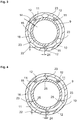
- a radial play 22 is provided due to manufacturing inaccuracies in which relative radial movement between the components 9, 10 is initially possible. Due to the axial length of the ratchet sleeve 9 and the number sleeve 10, the radial play 22 may vary in axial direction of the sleeves. Further, a rotational play 24 is provided, in which relative rotational movement between the components 9, 10 is initially possible. To minimize the possible relative radial or rotational movement, the number sleeve 10 is provided with a number of crush ribs 23 on its inner surface 15, which extend in a longitudinal direction parallel to the longitudinal axis 5 of the drug delivery device 1 (see fig. 2 ). The crush ribs 23 are arranged in such way that they are distributed around the inner periphery of the number sleeve 10 in a rotationally symmetric matter (see fig. 3 ).
- the crush ribs 23 are made of thermoplastic elastomer, are molded on the number sleeve 10 in a two-step molding process and are attached to the number sleeve 10 herewith.
- the crush ribs 23 have an oval cross-section with a circumferential inner section of the crush ribs 23 contacting the outer surface 16 of the ratchet sleeve 9 wherein the crush ribs 23 have been compressed in radial direction when the ratchet sleeve 9 was installed within the number sleeve 10.
- Fig. 3 shows the crush ribs 23 in a pre-stressed state.
- the ratchet sleeve 9 When vibrations are induced into the ratchet sleeve 9, the ratchet sleeve 9 is forced to vibrate. As the crush ribs 23 are closely connected to each other and are preferably able to deform elastically, the relative movement between the ratchet sleeve 9 and the number sleeve 10 in radial or circumferential direction has to override a resistance and is thereby effectively reduced without the inner surface 15 of the number sleeve 10 making direct contact with the outer surface 16 of the ratchet sleeve 9. Thereby, vibrations are damped and absorbed and the sound that is produced during dose dialing and dose cancellation is effectively reduced.
- the further embodiment shown in fig. 4 differs from the design in fig. 3 in the cross sectional shape of the crush ribs 23.
- the crush elements 23 in fig. 4 have a triangular cross-section.
- the apex 25 of the triangle or one corner of the triangle, respectively, is directed towards the circle center of the number sleeve 10.
- the triangular shape minimizes the contact surface at the apex 25 with the ratchet sleeve 9 thereby effectively reducing friction during relative movement of the number sleeve 10 and the ratchet sleeve 9.
Landscapes
- Health & Medical Sciences (AREA)
- Vascular Medicine (AREA)
- Engineering & Computer Science (AREA)
- Anesthesiology (AREA)
- Biomedical Technology (AREA)
- Heart & Thoracic Surgery (AREA)
- Hematology (AREA)
- Life Sciences & Earth Sciences (AREA)
- Animal Behavior & Ethology (AREA)
- General Health & Medical Sciences (AREA)
- Public Health (AREA)
- Veterinary Medicine (AREA)
- Infusion, Injection, And Reservoir Apparatuses (AREA)
Priority Applications (1)
| Application Number | Priority Date | Filing Date | Title |
|---|---|---|---|
| EP13786265.2A EP2916890B1 (en) | 2012-11-08 | 2013-11-05 | Dose setting mechanism for a drug delivery device |
Applications Claiming Priority (3)
| Application Number | Priority Date | Filing Date | Title |
|---|---|---|---|
| EP12191749 | 2012-11-08 | ||
| PCT/EP2013/073077 WO2014072298A1 (en) | 2012-11-08 | 2013-11-05 | Dose setting mechanism for a drug delivery device |
| EP13786265.2A EP2916890B1 (en) | 2012-11-08 | 2013-11-05 | Dose setting mechanism for a drug delivery device |
Publications (2)
| Publication Number | Publication Date |
|---|---|
| EP2916890A1 EP2916890A1 (en) | 2015-09-16 |
| EP2916890B1 true EP2916890B1 (en) | 2021-08-18 |
Family
ID=47172484
Family Applications (1)
| Application Number | Title | Priority Date | Filing Date |
|---|---|---|---|
| EP13786265.2A Active EP2916890B1 (en) | 2012-11-08 | 2013-11-05 | Dose setting mechanism for a drug delivery device |
Country Status (7)
| Country | Link |
|---|---|
| US (1) | US9789258B2 (xx) |
| EP (1) | EP2916890B1 (xx) |
| JP (1) | JP2015533321A (xx) |
| CN (1) | CN104768597A (xx) |
| DK (1) | DK2916890T3 (xx) |
| HK (1) | HK1210070A1 (xx) |
| WO (1) | WO2014072298A1 (xx) |
Families Citing this family (7)
| Publication number | Priority date | Publication date | Assignee | Title |
|---|---|---|---|---|
| USD752211S1 (en) * | 2012-08-01 | 2016-03-22 | Sanofi-Aventis Deutschland Gmbh | Injection device |
| USD752738S1 (en) * | 2013-09-20 | 2016-03-29 | Sanofi-Aventis Deutschland Gmbh | Injection device |
| USD743538S1 (en) * | 2014-01-17 | 2015-11-17 | Sanofi-Aventis Deutschland Gmbh | Injection device |
| CN105480650A (zh) * | 2015-12-18 | 2016-04-13 | 重庆路格科技有限公司 | 振动式送料筒 |
| EP3570914A1 (en) | 2017-01-23 | 2019-11-27 | Sanofi | Drive train for dial of a torsion-spring assisted wind-up injection device |
| US11666709B2 (en) | 2017-12-21 | 2023-06-06 | Sanofi | Drive mechanism with noise reduction |
| US20210038824A1 (en) * | 2018-03-13 | 2021-02-11 | Sanofi | Drive Train for Dial of a Torsion-Spring Assisted Wind-Up Injection Device |
Family Cites Families (9)
| Publication number | Priority date | Publication date | Assignee | Title |
|---|---|---|---|---|
| DE3715258C2 (de) | 1987-05-08 | 1996-10-31 | Haselmeier Wilhelm Fa | Injektionsgerät |
| EP1904131A2 (en) * | 2005-06-21 | 2008-04-02 | Eli Lilly And Company | Apparatus and method for injecting a pharmaceutical |
| EP2060288A1 (en) | 2007-11-13 | 2009-05-20 | F.Hoffmann-La Roche Ag | Administration device having input unit |
| DE102008011885A1 (de) * | 2008-02-29 | 2009-09-10 | Tecpharma Licensing Ag | Doppelfunktionsfeder |
| EP2275159A1 (en) * | 2009-07-14 | 2011-01-19 | Sanofi-Aventis Deutschland GmbH | Drug delivery device |
| EP3733231B1 (en) * | 2009-12-01 | 2021-12-29 | Becton, Dickinson and Company | Injection pen with dial back and last dose control |
| DE202011110769U1 (de) * | 2010-06-11 | 2016-04-07 | Sanofi-Aventis Deutschland Gmbh | Antriebsanordnung, Antriebskomponente und Arzneimittelabgabevorrichtung |
| RU2014128518A (ru) | 2011-12-29 | 2016-02-20 | Ново Нордиск А/С | Механизм увеличения/уменьшения дозы для взводимого шприца-ручки |
| BR112014029499A2 (pt) * | 2012-05-31 | 2017-06-27 | Novo Nordisk As | dispositivo de injeção conduzido por mola de torção |
-
2013
- 2013-11-05 US US14/435,797 patent/US9789258B2/en active Active
- 2013-11-05 EP EP13786265.2A patent/EP2916890B1/en active Active
- 2013-11-05 JP JP2015540163A patent/JP2015533321A/ja active Pending
- 2013-11-05 WO PCT/EP2013/073077 patent/WO2014072298A1/en active Application Filing
- 2013-11-05 DK DK13786265.2T patent/DK2916890T3/da active
- 2013-11-05 CN CN201380057728.1A patent/CN104768597A/zh active Pending
-
2015
- 2015-11-09 HK HK15111016.0A patent/HK1210070A1/xx unknown
Also Published As
| Publication number | Publication date |
|---|---|
| DK2916890T3 (da) | 2021-11-08 |
| EP2916890A1 (en) | 2015-09-16 |
| WO2014072298A1 (en) | 2014-05-15 |
| US20150265771A1 (en) | 2015-09-24 |
| HK1210070A1 (en) | 2016-04-15 |
| JP2015533321A (ja) | 2015-11-24 |
| US9789258B2 (en) | 2017-10-17 |
| CN104768597A (zh) | 2015-07-08 |
Similar Documents
| Publication | Publication Date | Title |
|---|---|---|
| US11654245B2 (en) | Assembly for a drug delivery device comprising a feedback feature | |
| EP2968784B1 (en) | Assembly for a drug delivery device comprising a feedback feature | |
| EP2916890B1 (en) | Dose setting mechanism for a drug delivery device | |
| EP3003432B1 (en) | Drive assembly for a drug delivery device and drug delivery device | |
| CA2815008A1 (en) | Drive mechanism for a drug delivery device and drug delivery device | |
| EP2895218B1 (en) | Drive mechanism for a drug delivery device and drug delivery device | |
| EP2996743B1 (en) | Assembly for a drug delivery device and drug delivery device | |
| EP2654858B1 (en) | Injection device with dose setting mechanism having maximum dose stop | |
| EP2968786B1 (en) | Assembly for a drug delivery device comprising a feedback feature | |
| EP3003439B1 (en) | Assembly for a drug delivery device and drug delivery device | |
| EP2968780B1 (en) | Assembly for a drug delivery device | |
| US10420890B2 (en) | Assembly for a drug delivery device and use of an attenuation member | |
| US10357613B2 (en) | Assembly for a drug delivery device | |
| EP2950857B1 (en) | Assembly for a drug delivery device | |
| EP3068470B1 (en) | Assembly for a drug delivery device and drug delivery device |
Legal Events
| Date | Code | Title | Description |
|---|---|---|---|
| PUAI | Public reference made under article 153(3) epc to a published international application that has entered the european phase |
Free format text: ORIGINAL CODE: 0009012 |
|
| STAA | Information on the status of an ep patent application or granted ep patent |
Free format text: STATUS: REQUEST FOR EXAMINATION WAS MADE |
|
| 17P | Request for examination filed |
Effective date: 20150608 |
|
| AK | Designated contracting states |
Kind code of ref document: A1 Designated state(s): AL AT BE BG CH CY CZ DE DK EE ES FI FR GB GR HR HU IE IS IT LI LT LU LV MC MK MT NL NO PL PT RO RS SE SI SK SM TR |
|
| AX | Request for extension of the european patent |
Extension state: BA ME |
|
| DAX | Request for extension of the european patent (deleted) | ||
| REG | Reference to a national code |
Ref country code: HK Ref legal event code: DE Ref document number: 1210070 Country of ref document: HK |
|
| GRAP | Despatch of communication of intention to grant a patent |
Free format text: ORIGINAL CODE: EPIDOSNIGR1 |
|
| STAA | Information on the status of an ep patent application or granted ep patent |
Free format text: STATUS: GRANT OF PATENT IS INTENDED |
|
| INTG | Intention to grant announced |
Effective date: 20210413 |
|
| GRAS | Grant fee paid |
Free format text: ORIGINAL CODE: EPIDOSNIGR3 |
|
| GRAA | (expected) grant |
Free format text: ORIGINAL CODE: 0009210 |
|
| STAA | Information on the status of an ep patent application or granted ep patent |
Free format text: STATUS: THE PATENT HAS BEEN GRANTED |
|
| AK | Designated contracting states |
Kind code of ref document: B1 Designated state(s): AL AT BE BG CH CY CZ DE DK EE ES FI FR GB GR HR HU IE IS IT LI LT LU LV MC MK MT NL NO PL PT RO RS SE SI SK SM TR |
|
| REG | Reference to a national code |
Ref country code: GB Ref legal event code: FG4D |
|
| REG | Reference to a national code |
Ref country code: CH Ref legal event code: EP |
|
| REG | Reference to a national code |
Ref country code: DE Ref legal event code: R096 Ref document number: 602013078853 Country of ref document: DE |
|
| REG | Reference to a national code |
Ref country code: IE Ref legal event code: FG4D Ref country code: AT Ref legal event code: REF Ref document number: 1421057 Country of ref document: AT Kind code of ref document: T Effective date: 20210915 |
|
| REG | Reference to a national code |
Ref country code: DK Ref legal event code: T3 Effective date: 20211104 |
|
| REG | Reference to a national code |
Ref country code: LT Ref legal event code: MG9D |
|
| REG | Reference to a national code |
Ref country code: NL Ref legal event code: MP Effective date: 20210818 |
|
| REG | Reference to a national code |
Ref country code: AT Ref legal event code: MK05 Ref document number: 1421057 Country of ref document: AT Kind code of ref document: T Effective date: 20210818 |
|
| PG25 | Lapsed in a contracting state [announced via postgrant information from national office to epo] |
Ref country code: AT Free format text: LAPSE BECAUSE OF FAILURE TO SUBMIT A TRANSLATION OF THE DESCRIPTION OR TO PAY THE FEE WITHIN THE PRESCRIBED TIME-LIMIT Effective date: 20210818 Ref country code: BG Free format text: LAPSE BECAUSE OF FAILURE TO SUBMIT A TRANSLATION OF THE DESCRIPTION OR TO PAY THE FEE WITHIN THE PRESCRIBED TIME-LIMIT Effective date: 20211118 Ref country code: LT Free format text: LAPSE BECAUSE OF FAILURE TO SUBMIT A TRANSLATION OF THE DESCRIPTION OR TO PAY THE FEE WITHIN THE PRESCRIBED TIME-LIMIT Effective date: 20210818 Ref country code: PT Free format text: LAPSE BECAUSE OF FAILURE TO SUBMIT A TRANSLATION OF THE DESCRIPTION OR TO PAY THE FEE WITHIN THE PRESCRIBED TIME-LIMIT Effective date: 20211220 Ref country code: RS Free format text: LAPSE BECAUSE OF FAILURE TO SUBMIT A TRANSLATION OF THE DESCRIPTION OR TO PAY THE FEE WITHIN THE PRESCRIBED TIME-LIMIT Effective date: 20210818 Ref country code: NO Free format text: LAPSE BECAUSE OF FAILURE TO SUBMIT A TRANSLATION OF THE DESCRIPTION OR TO PAY THE FEE WITHIN THE PRESCRIBED TIME-LIMIT Effective date: 20211118 Ref country code: FI Free format text: LAPSE BECAUSE OF FAILURE TO SUBMIT A TRANSLATION OF THE DESCRIPTION OR TO PAY THE FEE WITHIN THE PRESCRIBED TIME-LIMIT Effective date: 20210818 Ref country code: ES Free format text: LAPSE BECAUSE OF FAILURE TO SUBMIT A TRANSLATION OF THE DESCRIPTION OR TO PAY THE FEE WITHIN THE PRESCRIBED TIME-LIMIT Effective date: 20210818 Ref country code: SE Free format text: LAPSE BECAUSE OF FAILURE TO SUBMIT A TRANSLATION OF THE DESCRIPTION OR TO PAY THE FEE WITHIN THE PRESCRIBED TIME-LIMIT Effective date: 20210818 Ref country code: HR Free format text: LAPSE BECAUSE OF FAILURE TO SUBMIT A TRANSLATION OF THE DESCRIPTION OR TO PAY THE FEE WITHIN THE PRESCRIBED TIME-LIMIT Effective date: 20210818 |
|
| PG25 | Lapsed in a contracting state [announced via postgrant information from national office to epo] |
Ref country code: PL Free format text: LAPSE BECAUSE OF FAILURE TO SUBMIT A TRANSLATION OF THE DESCRIPTION OR TO PAY THE FEE WITHIN THE PRESCRIBED TIME-LIMIT Effective date: 20210818 Ref country code: LV Free format text: LAPSE BECAUSE OF FAILURE TO SUBMIT A TRANSLATION OF THE DESCRIPTION OR TO PAY THE FEE WITHIN THE PRESCRIBED TIME-LIMIT Effective date: 20210818 Ref country code: GR Free format text: LAPSE BECAUSE OF FAILURE TO SUBMIT A TRANSLATION OF THE DESCRIPTION OR TO PAY THE FEE WITHIN THE PRESCRIBED TIME-LIMIT Effective date: 20211119 |
|
| PG25 | Lapsed in a contracting state [announced via postgrant information from national office to epo] |
Ref country code: NL Free format text: LAPSE BECAUSE OF FAILURE TO SUBMIT A TRANSLATION OF THE DESCRIPTION OR TO PAY THE FEE WITHIN THE PRESCRIBED TIME-LIMIT Effective date: 20210818 |
|
| REG | Reference to a national code |
Ref country code: DE Ref legal event code: R097 Ref document number: 602013078853 Country of ref document: DE |
|
| REG | Reference to a national code |
Ref country code: HK Ref legal event code: WD Ref document number: 1210070 Country of ref document: HK |
|
| PG25 | Lapsed in a contracting state [announced via postgrant information from national office to epo] |
Ref country code: SM Free format text: LAPSE BECAUSE OF FAILURE TO SUBMIT A TRANSLATION OF THE DESCRIPTION OR TO PAY THE FEE WITHIN THE PRESCRIBED TIME-LIMIT Effective date: 20210818 Ref country code: SK Free format text: LAPSE BECAUSE OF FAILURE TO SUBMIT A TRANSLATION OF THE DESCRIPTION OR TO PAY THE FEE WITHIN THE PRESCRIBED TIME-LIMIT Effective date: 20210818 Ref country code: RO Free format text: LAPSE BECAUSE OF FAILURE TO SUBMIT A TRANSLATION OF THE DESCRIPTION OR TO PAY THE FEE WITHIN THE PRESCRIBED TIME-LIMIT Effective date: 20210818 Ref country code: EE Free format text: LAPSE BECAUSE OF FAILURE TO SUBMIT A TRANSLATION OF THE DESCRIPTION OR TO PAY THE FEE WITHIN THE PRESCRIBED TIME-LIMIT Effective date: 20210818 Ref country code: CZ Free format text: LAPSE BECAUSE OF FAILURE TO SUBMIT A TRANSLATION OF THE DESCRIPTION OR TO PAY THE FEE WITHIN THE PRESCRIBED TIME-LIMIT Effective date: 20210818 Ref country code: AL Free format text: LAPSE BECAUSE OF FAILURE TO SUBMIT A TRANSLATION OF THE DESCRIPTION OR TO PAY THE FEE WITHIN THE PRESCRIBED TIME-LIMIT Effective date: 20210818 |
|
| PLBE | No opposition filed within time limit |
Free format text: ORIGINAL CODE: 0009261 |
|
| STAA | Information on the status of an ep patent application or granted ep patent |
Free format text: STATUS: NO OPPOSITION FILED WITHIN TIME LIMIT |
|
| PG25 | Lapsed in a contracting state [announced via postgrant information from national office to epo] |
Ref country code: MC Free format text: LAPSE BECAUSE OF FAILURE TO SUBMIT A TRANSLATION OF THE DESCRIPTION OR TO PAY THE FEE WITHIN THE PRESCRIBED TIME-LIMIT Effective date: 20210818 |
|
| 26N | No opposition filed |
Effective date: 20220519 |
|
| PG25 | Lapsed in a contracting state [announced via postgrant information from national office to epo] |
Ref country code: LU Free format text: LAPSE BECAUSE OF NON-PAYMENT OF DUE FEES Effective date: 20211105 Ref country code: IT Free format text: LAPSE BECAUSE OF FAILURE TO SUBMIT A TRANSLATION OF THE DESCRIPTION OR TO PAY THE FEE WITHIN THE PRESCRIBED TIME-LIMIT Effective date: 20210818 Ref country code: BE Free format text: LAPSE BECAUSE OF NON-PAYMENT OF DUE FEES Effective date: 20211130 |
|
| REG | Reference to a national code |
Ref country code: BE Ref legal event code: MM Effective date: 20211130 |
|
| PG25 | Lapsed in a contracting state [announced via postgrant information from national office to epo] |
Ref country code: SI Free format text: LAPSE BECAUSE OF FAILURE TO SUBMIT A TRANSLATION OF THE DESCRIPTION OR TO PAY THE FEE WITHIN THE PRESCRIBED TIME-LIMIT Effective date: 20210818 |
|
| PG25 | Lapsed in a contracting state [announced via postgrant information from national office to epo] |
Ref country code: IE Free format text: LAPSE BECAUSE OF NON-PAYMENT OF DUE FEES Effective date: 20211105 |
|
| PG25 | Lapsed in a contracting state [announced via postgrant information from national office to epo] |
Ref country code: HU Free format text: LAPSE BECAUSE OF FAILURE TO SUBMIT A TRANSLATION OF THE DESCRIPTION OR TO PAY THE FEE WITHIN THE PRESCRIBED TIME-LIMIT; INVALID AB INITIO Effective date: 20131105 |
|
| PG25 | Lapsed in a contracting state [announced via postgrant information from national office to epo] |
Ref country code: CY Free format text: LAPSE BECAUSE OF FAILURE TO SUBMIT A TRANSLATION OF THE DESCRIPTION OR TO PAY THE FEE WITHIN THE PRESCRIBED TIME-LIMIT Effective date: 20210818 |
|
| PGFP | Annual fee paid to national office [announced via postgrant information from national office to epo] |
Ref country code: TR Payment date: 20231103 Year of fee payment: 11 Ref country code: DK Payment date: 20231116 Year of fee payment: 11 Ref country code: DE Payment date: 20230912 Year of fee payment: 11 |
|
| PG25 | Lapsed in a contracting state [announced via postgrant information from national office to epo] |
Ref country code: MK Free format text: LAPSE BECAUSE OF FAILURE TO SUBMIT A TRANSLATION OF THE DESCRIPTION OR TO PAY THE FEE WITHIN THE PRESCRIBED TIME-LIMIT Effective date: 20210818 |
|
| PGFP | Annual fee paid to national office [announced via postgrant information from national office to epo] |
Ref country code: CH Payment date: 20240127 Year of fee payment: 11 |
|
| PG25 | Lapsed in a contracting state [announced via postgrant information from national office to epo] |
Ref country code: MT Free format text: LAPSE BECAUSE OF FAILURE TO SUBMIT A TRANSLATION OF THE DESCRIPTION OR TO PAY THE FEE WITHIN THE PRESCRIBED TIME-LIMIT Effective date: 20210818 |
|
| PGFP | Annual fee paid to national office [announced via postgrant information from national office to epo] |
Ref country code: GB Payment date: 20240912 Year of fee payment: 12 |
|
| PGFP | Annual fee paid to national office [announced via postgrant information from national office to epo] |
Ref country code: FR Payment date: 20240909 Year of fee payment: 12 |