EP2916883B1 - Verfahren zur herstellung einer stentgraft-prothese mit zwei lagen von expandiertem polytetrafluorethylen - Google Patents
Verfahren zur herstellung einer stentgraft-prothese mit zwei lagen von expandiertem polytetrafluorethylen Download PDFInfo
- Publication number
- EP2916883B1 EP2916883B1 EP13792184.7A EP13792184A EP2916883B1 EP 2916883 B1 EP2916883 B1 EP 2916883B1 EP 13792184 A EP13792184 A EP 13792184A EP 2916883 B1 EP2916883 B1 EP 2916883B1
- Authority
- EP
- European Patent Office
- Prior art keywords
- eptfe
- stent
- layer
- mandrel
- layers
- Prior art date
- Legal status (The legal status is an assumption and is not a legal conclusion. Google has not performed a legal analysis and makes no representation as to the accuracy of the status listed.)
- Active
Links
Images



Classifications
-
- A—HUMAN NECESSITIES
- A61—MEDICAL OR VETERINARY SCIENCE; HYGIENE
- A61L—METHODS OR APPARATUS FOR STERILISING MATERIALS OR OBJECTS IN GENERAL; DISINFECTION, STERILISATION OR DEODORISATION OF AIR; CHEMICAL ASPECTS OF BANDAGES, DRESSINGS, ABSORBENT PADS OR SURGICAL ARTICLES; MATERIALS FOR BANDAGES, DRESSINGS, ABSORBENT PADS OR SURGICAL ARTICLES
- A61L31/00—Materials for other surgical articles, e.g. stents, stent-grafts, shunts, surgical drapes, guide wires, materials for adhesion prevention, occluding devices, surgical gloves, tissue fixation devices
- A61L31/04—Macromolecular materials
- A61L31/048—Macromolecular materials obtained by reactions only involving carbon-to-carbon unsaturated bonds
-
- B—PERFORMING OPERATIONS; TRANSPORTING
- B29—WORKING OF PLASTICS; WORKING OF SUBSTANCES IN A PLASTIC STATE IN GENERAL
- B29D—PRODUCING PARTICULAR ARTICLES FROM PLASTICS OR FROM SUBSTANCES IN A PLASTIC STATE
- B29D23/00—Producing tubular articles
-
- A—HUMAN NECESSITIES
- A61—MEDICAL OR VETERINARY SCIENCE; HYGIENE
- A61F—FILTERS IMPLANTABLE INTO BLOOD VESSELS; PROSTHESES; DEVICES PROVIDING PATENCY TO, OR PREVENTING COLLAPSING OF, TUBULAR STRUCTURES OF THE BODY, e.g. STENTS; ORTHOPAEDIC, NURSING OR CONTRACEPTIVE DEVICES; FOMENTATION; TREATMENT OR PROTECTION OF EYES OR EARS; BANDAGES, DRESSINGS OR ABSORBENT PADS; FIRST-AID KITS
- A61F2/00—Filters implantable into blood vessels; Prostheses, i.e. artificial substitutes or replacements for parts of the body; Appliances for connecting them with the body; Devices providing patency to, or preventing collapsing of, tubular structures of the body, e.g. stents
- A61F2/02—Prostheses implantable into the body
- A61F2/04—Hollow or tubular parts of organs, e.g. bladders, tracheae, bronchi or bile ducts
- A61F2/06—Blood vessels
- A61F2/07—Stent-grafts
-
- A—HUMAN NECESSITIES
- A61—MEDICAL OR VETERINARY SCIENCE; HYGIENE
- A61F—FILTERS IMPLANTABLE INTO BLOOD VESSELS; PROSTHESES; DEVICES PROVIDING PATENCY TO, OR PREVENTING COLLAPSING OF, TUBULAR STRUCTURES OF THE BODY, e.g. STENTS; ORTHOPAEDIC, NURSING OR CONTRACEPTIVE DEVICES; FOMENTATION; TREATMENT OR PROTECTION OF EYES OR EARS; BANDAGES, DRESSINGS OR ABSORBENT PADS; FIRST-AID KITS
- A61F2/00—Filters implantable into blood vessels; Prostheses, i.e. artificial substitutes or replacements for parts of the body; Appliances for connecting them with the body; Devices providing patency to, or preventing collapsing of, tubular structures of the body, e.g. stents
- A61F2/02—Prostheses implantable into the body
- A61F2/04—Hollow or tubular parts of organs, e.g. bladders, tracheae, bronchi or bile ducts
- A61F2/06—Blood vessels
- A61F2/07—Stent-grafts
- A61F2002/072—Encapsulated stents, e.g. wire or whole stent embedded in lining
-
- Y—GENERAL TAGGING OF NEW TECHNOLOGICAL DEVELOPMENTS; GENERAL TAGGING OF CROSS-SECTIONAL TECHNOLOGIES SPANNING OVER SEVERAL SECTIONS OF THE IPC; TECHNICAL SUBJECTS COVERED BY FORMER USPC CROSS-REFERENCE ART COLLECTIONS [XRACs] AND DIGESTS
- Y10—TECHNICAL SUBJECTS COVERED BY FORMER USPC
- Y10T—TECHNICAL SUBJECTS COVERED BY FORMER US CLASSIFICATION
- Y10T156/00—Adhesive bonding and miscellaneous chemical manufacture
- Y10T156/10—Methods of surface bonding and/or assembly therefor
- Y10T156/1002—Methods of surface bonding and/or assembly therefor with permanent bending or reshaping or surface deformation of self sustaining lamina
- Y10T156/1028—Methods of surface bonding and/or assembly therefor with permanent bending or reshaping or surface deformation of self sustaining lamina by bending, drawing or stretch forming sheet to assume shape of configured lamina while in contact therewith
- Y10T156/103—Encasing or enveloping the configured lamina
Definitions
- the invention relates generally to methods of manufacturing a stent-graft prosthesis formed with two layers of expanded polytetrafluoroethylene (ePTFE).
- ePTFE expanded polytetrafluoroethylene
- US 2001/039446 A1 describes an encapsulated intraluminal stent-graft and methods of making same.
- WO 98/38947 A1 describes a conformal laminate stent device.
- WO 03/057075 A2 describes a hybrid intravascular stent.
- US 6 547 814 B2 describes selective adherence of stent-graft coverings.
- Aneurysms result from weak blood vessel walls which can balloon due to aging and disease and pressure in the vessel.
- aneurysmal vessels have a potential to rupture, causing internal bleeding and potentially life threatening conditions.
- Grafts are used to isolate aneurysms or other blood vessel abnormalities from normal blood pressure, reducing pressure on the weakened vessel wall and reducing the chance of vessel rupture.
- a tubular endovascular graft is placed within the aneurysmal blood vessel to create a new flow path and an artificial flow conduit through the aneurysm, thereby reducing if not nearly eliminating the exertion of blood pressure on the aneurysm.
- the graft typically incorporates or is combined with one or more radially expandable stent(s) to be radially expanded in situ to anchor the tubular graft to the wall of the blood vessel at sites upstream and downstream of the aneurysm.
- endovascular grafts are typically held in place by mechanical engagement and friction because of the force of the self-expanding or balloon expandable stents.
- Expanded polytetrafluoroethylene or ePTFE is a polymeric material that may be used as the graft material of a stent-graft prosthesis. It is known in the art to form a stent-graft prosthesis that includes a sheet or film of ePTFE which covers or lines at least one stent, as described in, for example, U.S. Pat. Nos. 5,700,285 and 5,735,892 to Myers et al.
- a stent-graft prosthesis that includes an inner PTFE tubular structure, an outer PTFE tubular structure positioned about the inner PTFE tubular structure and at least one stent interposed or encapsulated between the inner and outer PTFE tubular structures, as described in, for example, U.S. Pat. No. 6,673,103 to Golds et al.
- Embodiments hereof relate to methods of manufacture for a stent-graft prosthesis having at least one stent positioned between or encapsulated within two layers of ePTFE, wherein the methods utilize direct heating elements to reduce baking temperatures and/or reduce baking times required to couple the two layers of ePTFE together.
- the methods described herein may be utilized to form a stent-graft prosthesis without an intermediary adhesive or melt layer between the two layers of ePTFE.
- the invention relates to a method of manufacturing a stent-graft prosthesis in accordance with appended claims 1 and 7.
- a method of manufacturing a stent-graft prosthesis for implantation within a blood vessel A first layer of ePTFE is positioned over a mandrel, the mandrel including at least one heating element positioned within a lumen defined by the mandrel. At least one annular stent is positioned onto the first layer of ePTFE, and a second layer of ePTFE is positioned over the stent and the first layer of ePTFE. A heat shrink material is positioned over the second layer of ePTFE such that the heat shrink material fully covers the first and second layers of ePTFE.
- the first and second layers of ePTFE are heated with the heating element within the mandrel at a temperature to couple together the first and second layers of ePTFE such that the first layer of ePTFE, the at least one stent, and the second layer of ePTFE form the stent-graft prosthesis.
- the heating step occurs for four minutes or less.
- the heat shrink material is removed from the stent-graft prosthesis, and then the stent-graft prosthesis is removed from the mandrel.
- a method in which a first layer of ePTFE is positioned over a mandrel, and an external heating element is positioned around the mandrel such that an inner surface thereof is spaced apart less than 38.1 mm (1.5 inches) from an outer surface of the mandrel.
- At least one annular stent is positioned onto the first layer of ePTFE, and a second layer of ePTFE is positioned over the stent and the first layer of ePTFE.
- a heat shrink material is positioned over the second layer of ePTFE such that the heat shrink material fully covers the first and second layers of ePTFE.
- the first and second layers of ePTFE are heated with the external heating element at a temperature to couple together the first and second layers of ePTFE such that the first layer of ePTFE, the at least one stent, and the second layer of ePTFE form the stent-graft prosthesis.
- the heating step occurs for four minutes or less.
- the heat shrink material is removed from the stent-graft prosthesis, and then the stent-graft prosthesis is removed from the mandrel.
- a method in which a first layer of ePTFE is positioned over a mandrel. At least one heating element is positioned within or around the mandrel. At least one annular stent is positioned onto the first layer of ePTFE, and a second layer of ePTFE is positioned over the stent and the first layer of ePTFE. A heat shrink material is positioned over the second layer of ePTFE such that the heat shrink material fully covers the first and second layers of ePTFE.
- the first and second layers of ePTFE are heated with the heating element at a temperature to entangle the first and second layers of ePTFE on a molecular level such that the first layer of ePTFE, the at least one stent, and the second layer of ePTFE form the stent-graft prosthesis.
- the stent-graft prosthesis does not include an intermediary melt layer between the first and second layers of ePTFE.
- the heating step occurs for four minutes or less. The heat shrink material is removed from the stent-graft prosthesis, and then the stent-graft prosthesis is removed from the mandrel.
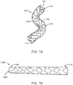
- FIG. 1A illustrates a perspective view of a stent-graft prosthesis 100 in a deployed or expanded state or configuration.
- Stent-graft prosthesis 100 includes a generally tubular or cylindrical body 108 that defines a lumen 106 there through and has a first edge or end 110 and a second edge or end 112.
- Tubular body 108 includes graft material 102 and at least one radially-compressible stent or scaffold 104 for supporting the graft material and that is operable to self-expand into apposition with an interior wall of a body vessel (not shown).
- Graft material 102 includes two layers of expanded polytetrafluoroethylene (ePTFE), as will be explained in more detail herein.
- ePTFE expanded polytetrafluoroethylene
- Stent 104 is constructed from a self-expanding or spring material, and has sufficient radial spring force and flexibility to conformingly engage stent-graft prosthesis 100 with the blood vessel inner wall, to avoid excessive leakage, and prevent pressurization of the aneurysm, i.e., to provide a leak-resistant seal.
- self-expanding is used in the following description with reference to one or more stent structures of the prostheses hereof and is intended to convey that the structures are shaped or formed from a material that can be provided with a mechanical memory to return the structure from a compressed or constricted delivery configuration to an expanded deployed configuration.
- Non-exhaustive exemplary self-expanding materials include stainless steel, a super-elastic metal such as a nickel titanium alloy or Nitinol, various polymers, or a so-called super alloy, which may have a base metal of nickel, cobalt, chromium, or other metal.
- Mechanical memory may be imparted to a wire or stent structure by thermal treatment to achieve a spring temper in stainless steel, for example, or to set a shape memory in a susceptible metal alloy, such as Nitinol.
- Various polymers that can be made to have shape memory characteristics may also be suitable for use in embodiments hereof to include polymers such as polynorborene, trans-polyisoprene, styrene-butadiene, and polyurethane.
- polymers such as polynorborene, trans-polyisoprene, styrene-butadiene, and polyurethane.
- poly L-D lactic copolymer, oligo caprylactone copolymer and poly cyclo-octine can be used separately or in conjunction with other shape memory polymers.
- stent 104 may be balloon-expandable and formed from a suitable material such as steel.
- stent-graft prosthesis 100 is merely exemplary and that the methods of forming a stent-graft prosthesis as described herein may be utilized to form stent-grafts of various other configurations.
- the support structure or stent of the stent-graft prosthesis may be a unitary tubular stent component having diamond-shaped openings or cells, which may be formed by various conventional stent forming methods as would be understood by one of ordinary skill in the art, rather than a plurality of stents formed as independent sinusoidal patterned rings.
- the stent may be formed from a wire bent into a waveform and helically wrapped to form the stent, as is known in the art.
- the stent-graft prosthesis is not required to have a cylindrical configuration.
- FIG. 1B illustrates a stent-graft prosthesis 100B having a generally tubular configuration that defines a lumen 106B there through and has a first edge or end 110B and a second flared edge or end 112B, wherein second end 112B has a larger diameter than first end 110B.
- Embodiments hereof relate to methods of forming a stent-graft, such as stent-graft prosthesis 100, having graft material formed via two layers of ePTFE with at least one stent being positioned between or encapsulated within the ePTFE layers.
- the methods disclosed herein utilize one or more direct heating elements that are positioned within or in close proximity to the stent-graft prosthesis, as compared to an air oven. By utilizing one or more heating elements in close proximity to the stent-graft prosthesis, both the temperature and time required to couple the two ePTFE layers together is reduced as compared to baking in an air oven.
- the direct heating elements may be utilized to couple the two layers of ePTFE together without an adhesive or melt layer therebetween.
- ePTFE includes a microstructure of nodes interconnected by fibrils. Quickly heating the ePTFE layers allows the nodes and fibrils of the ePTFE layers to entangle on a molecular level while generating minimal temperature induced strain into the stent material.
- the elimination of the adhesive or melt layer is advantageous because the melt layer may be difficult and timely to uniformly place over the first ePTFE layer.
- the resulting stent-graft prosthesis may be thicker, thus having a greater profile, and stiffer than a stent-graft prosthesis without a melt layer.
- FIG. 2 is a flow chart illustrating steps of a method of forming a stent-graft having graft material formed via two layers of ePTFE according to an embodiment hereof.
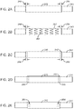
- a first layer of ePTFE tubing 242 is positioned over a mandrel 240 as shown in FIG. 2A and step 220 of FIG. 2 .
- the length of ePTFE tubing 242 is greater than the desired length of the stent-graft prosthesis, because ePTFE tubing includes first and second ends 248, 250 which are folded over or cuffed during the manufacturing process as will be explained in more detail herein.
- the length of ePTFE tubing is equal to the desired length of the stent-graft prosthesis plus the length of first and second ends 248, 250.
- mandrel 240 may include a tapered expansion tip (not shown) to ease or assist in positioning of tubing over the mandrel.
- the first layer of ePTFE tubing 242 is slid over the mandrel until it is approximately centered thereon, as shown in FIG. 2A .
- mandrel 240 is formed of stainless steel and may include a coating on an outer surface thereof.
- the coating is electroless nickel-phosphorous plating, commercially available from Bales Mold Service, Inc. of Downers Grove, IL under the tradename Nibore®. Electroless nickel-phosphorous becomes very hard when heated, and thus prevents bonding or adhesion between first layer of ePTFE tubing 242 and mandrel 240 during heating step 230 described herein.
- the coating is Kapton®, is a polyimide film developed by DuPont which can remain stable in a wide range of temperatures.
- mandrel 240 may alternatively be formed of polybenzlmidazole.
- Polybenzlmidazole is an inert biocompatible polymer material with a very high melting point and thus prevents bonding between first layer of ePTFE tubing 242 and mandrel 240 during heating step 230 described herein.
- each stent 204 is a sinusoidal patterned ring including a plurality of crowns or bends and a plurality of struts or straight segments with each crown being formed between a pair of opposing struts.
- Stents 204 are shown in FIG.
- stents 204 may have a different pattern or configuration.
- stents 204 are positioned onto the first layer of ePTFE at approximately equally-spaced intervals. Stents 204 may be oriented such that the crowns thereof are in line with each other and any joints/seams thereon are in line with each other, although such alignment is not required. Stents 204 are not positioned on first and second ends 248, 250 of first layer of ePTFE tubing 242 because the ends are folded over or cuffed in a later processing step as described in more detail with respect to FIG. 2E .
- Stents 204 may be self-expanding, as described above with respect to stent 104, or may be balloon-expandable.
- the support structure or stent of the stent-graft prosthesis may be a unitary tubular stent component having diamond-shaped openings or cells rather than a plurality of stents formed as independent sinusoidal patterned rings.
- the stent may be formed from a wire bent into a waveform and helically wrapped to form the stent, as is known in the art
- a second layer of ePTFE tubing 246 is then positioned directly over the first layer of ePTFE tubing 242 and stents 204 as shown in FIG. 2C and step 224 of FIG. 2 , without a melt layer being present between the first and second ePTFE layers such that portions of the ePTFE layers extending between stents 204 abut against each other.
- the length of ePTFE tubing 246 is approximately equal to the desired length of the stent-graft prosthesis.
- the second layer of ePTFE tubing 246 is slid over the first layer of ePTFE tubing 242 until it is approximately centered thereon, as shown in FIG.
- first and second ends 248, 250 are then folded over or cuffed. More particularly, first and second ends 248, 250 are then folded or rolled over such that an outer surface of first and second ends 248, 250 lay against or overlap onto a portion of an outer surface of second layer of ePTFE tubing 246, thereby forming cuffs having three layers of ePTFE on the ends of the assembled components or layers.
- first and second ends 248, 250 may each be approximately 5 mm in length.
- heat shrink tubing 252 is slid over the second layer of ePTFE tubing 246 until it is approximately centered thereon as shown in FIG. 2E and step 228 of FIG. 2 .
- heat shrink tubing is expanded tubing that will shrink when heat is applied thereto in an effort to return or recover to the relaxed diameter it originally had when extruded.
- heat shrink tubing 252 shrinks or recovers, it radially compresses the assembled components or layers during heating step 230 described herein to form the stent-graft prosthesis in a compressed or delivery configuration suitable for delivery into the vasculature.
- the length of heat shrink tubing 252 is greater than the length of second layer of ePTFE tubing 246 such that the heat shrink material completely/fully covers or extends over the assembled components or layers on mandrel 240.
- Heat shrink tubing 252 may include one or more slits or cuts 254, formed or made transverse to a longitudinal axis of the heat shrink tubing, at a first and/or second end or edge thereof to facilitate the step of removing the heat shrink material as will be described in more detail herein.
- Heat shrink tubing 252 is formed of a polymeric material such as polytetrafluoroethylene (PTFE) and may include a coating coupled to or on an inner surface thereof.
- PTFE polytetrafluoroethylene
- the coating is high temperature resistant parylene HT (high temperature), commercially available from Specialty Coatings Systems of Indianapolis, Indiana, which prevents bonding/adhesion between second layer of ePTFE tubing 246 and heat shrink tubing 252 during heating step 230 described herein.
- the parylene HT coating has a thickness not greater than five microns or micrometers in order to conform to the inner surface of heat shrink tubing 252, and in one embodiment, the parylene HT coating has a thickness not greater than one micron or micrometer.
- the parylene HT coating also results in a stent-graft prosthesis having a smooth, substantially wrinkle-free outer surface.
- a layer of aluminum foil may be utilized as a lining that extends along an inner surface of heat shrink tubing 252 to prevent bonding/coupling between second layer of ePTFE tubing 246 and heat shrink tubing 252 during heating step 230 described herein.
- At least one direct heating element or source at a required or prescribed temperature T HE is utilized to heat first and second ePTFE layers 242, 246 as shown in step 230 of FIG. 2 .
- T HE the heating element at temperature T HE
- the ePTFE layers 242, 246 are heated such that the nodes and fibrils of the ePTFE material entangle, intertwine, interweave, or otherwise mesh together, thereby coupling the first and second ePTFE layers together without an intermediary layer therebetween.
- required time or waiting period WP such that first and second ePTFE layers 242, 246 entangle, thereby forming the stent-graft prosthesis.
- required time or waiting period WP begins or occurs after the heating element has warmed up to temperature T HE and the equipment/heating element is considered to be at a steady state temperature of the prescribed/required temperature T HE .
- temperature T HE and waiting period WP depend upon the type of and proximity of the heating element(s) utilized herein.
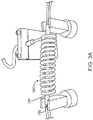
- the two heating elements include a first internal heating element 358 positioned within a lumen (not shown) of mandrel 240 and a second external heating element 360 surrounding mandrel 240 and positioned in close proximity thereto.
- the temperature T HE of internal heating element 358 is 250-290 °C and the temperature T HE of external heating element 360 is approximately 360 °C.
- approximately 360 °C includes temperatures ranging between 340-380 °C.
- Waiting period WP i.e ., the period of time it takes first and second ePTFE layers 242, 246 to couple together or entangle, is two minutes or less. In one embodiment, waiting period WP is approximately one minute.
- heating elements 358, 360 The relatively lower temperatures and relatively faster heating times described herein are due to the proximity of heating elements 358, 360.
- the proximity of heating elements 358, 360 allows the assembled components or layers on mandrel 240 to be heated using conduction, rather than convection as utilized in air ovens. By placing heating elements into and/or close to mandrel 240, heat can travel directly to first and second ePTFE layers 242, 246 to result in the short waiting periods WP described herein.
- the proximity of external heating element 360 results in a quick recovery or shrinking of heat shrink tubing 254 during the manufacturing process.
- the structural configurations of heating elements 358, 360 described herein are not required but rather the placement and described proximity of the heating element(s) is necessary to heat the ePTFE layers via conduction within the described temperatures T HE and waiting periods WP.
- Internal heating element 358 which is commercially available from manufacturers such as but not limited to Watlow Electric Manufacturing Company, is positioned within a lumen (not shown) of mandrel 240 and heats mandrel 240. When mandrel 240 is formed from conductive stainless steel, mandrel 240 reaches approximately the same temperature as heating element 358.
- External heating element 360 which is commercially available from manufacturers such as but not limited to Watlow Electric Manufacturing Company, circumferentially surrounds mandrel 240 and is positioned in close proximity thereto.
- external heating element 360 is a continuous coil or helix having an inner surface that is spaced apart between 0.508 to 38.1 mm (0.02 to 1.5 inches) from an outer surface of mandrel 240.
- the coil configuration of external heating element 360 is not required but it is necessary for the external heating element to be in close proximity to an outer surface of mandrel 240 as described herein.
- a heated metal die or tool having an inner surface that is heated to the temperatures T HE and is spaced apart between 0.508 to 38.1 mm (0.02 to 1.5 inches) from an outer surface of mandrel 240 may be utilized as external heating element 360.
- Heated metal dies or tools are known in the art of hot forming and may utilize a plurality of electrical heaters in separate electrically powered and controlled heating zones which may be very effective in providing close control of the temperature of the heated inner surface.
- heating element may be solely utilized in heating step 230.
- the temperature T HE of internal heating element 358 is between 250-290 °C and waiting period WP, i.e., the period of time it takes first and second ePTFE layers 242, 246 to couple together, is four minutes or less.
- mandrel 240 may be formed of stainless steel and may include an electroless nickel-phosphorous or Kapton® coating as described above to prevent bonding between first layer of ePTFE tubing 242 and mandrel 240 during the heating step.
- only external heating element 360 is utilized in heating step 230.
- the temperature T HE of external heating element 360 is approximately 360 °C and waiting period WP, i.e., the period of time it takes first and second ePTFE layers 242, 246 to couple together, is four minutes or less.
- mandrel 240 may be formed of polybenzlmidazole or may be formed of stainless steel with a coating thereon to prevent bonding between first layer of ePTFE tubing 242 and mandrel 240 during heating step 230 described herein.
- Polybenzlmidazole does not allow for heat transfer and thus would not be utilized as a material for mandrel 240 in any embodiment described herein in which an internal heating element is used within the mandrel.
- first and second ePTFE layers 242, 246 are entangled or coupled together, a stent-graft prosthesis is thereby formed.
- the stent-graft prosthesis has been radially compressed due to shrinkage of heat shrink tubing 252 and includes the first ePTFE layer 242, stents 204, and the ePTFE second layer 246.
- Heat shrink tubing 252 may then be removed as shown in step 232 of FIG. 2 .
- heat shrink tubing 252 may be ripped or torn off the stent-graft prosthesis by pulling at slits 254 formed therein.
- heat shrink tubing 252 includes a parylene HT coating on the inner surface thereof as described above, heat shrink tubing 252 advantageously cracks or snaps apart during removal thereof.
- the stent-graft prosthesis may also be removed from mandrel 240 as shown in step 234 of FIG. 2 . The stent-graft prosthesis may be removed from the mandrel by pulling or sliding it off.
- first and second ePTFE layers 242, 246 are directly or immediately entangled together without an adhesive or melt layer therebetween
- the melt layer may be a thermoplastic material that operates or functions to bond or tie the two layers of ePTFE together such as but not limited to fluoroethylpolypropylene (FEP), polytetrafluoroethylene, polyurethane, polyamide, polyimide or silicone. If an intermediary melt layer is present, the required time or waiting period required to bond first and second ePTFE layers 242, 246 together via melting or reflowing of the adhesive layer is equal to or less than the waiting periods WP described herein.
- FEP fluoroethylpolypropylene
- first and/or second ePTFE layers 242, 246 may be formed via ePTFE material which is not originally formed as a tubular component.
- first and/or second ePTFE layers 242, 246 may be formed via an elongated ribbon or band 470 of ePTFE that is wrapped around the outer surface of mandrel 240. Band 470 is wrapped or wound around mandrel 240 in a helical or corkscrew fashion to form a series of loops 472.
- Adjacent edges of loops 472 may slightly overlap or may abut against each other. In one embodiment, when forming second ePTFE layer 246, adjacent edges of loops 472 may be slightly spaced apart so long as loops 472 completely cover or extend over stent(s) 204. Gaps between loops 472 may provide the stent-graft prosthesis with additional flexibility while stent(s) 204 are still encapsulated by the ePFTE layers.
- first layer 242 may include one or more tubular ePTFE layers or components and/or second layer 246 may include one or more tubular ePTFE layers or components. If more than two layers of ePTFE are included, heating step 230 as described herein operates to entangle all layers of ePTFE together within the above-described waiting periods such that all of the ePTFE layers and the stent(s) form a stent-graft prosthesis.
Landscapes
- Health & Medical Sciences (AREA)
- Veterinary Medicine (AREA)
- Heart & Thoracic Surgery (AREA)
- Public Health (AREA)
- Life Sciences & Earth Sciences (AREA)
- Animal Behavior & Ethology (AREA)
- General Health & Medical Sciences (AREA)
- Vascular Medicine (AREA)
- Engineering & Computer Science (AREA)
- Transplantation (AREA)
- Biomedical Technology (AREA)
- Oral & Maxillofacial Surgery (AREA)
- Cardiology (AREA)
- Pulmonology (AREA)
- Gastroenterology & Hepatology (AREA)
- Chemical & Material Sciences (AREA)
- Chemical Kinetics & Catalysis (AREA)
- Surgery (AREA)
- Epidemiology (AREA)
- Mechanical Engineering (AREA)
- Prostheses (AREA)
- Materials For Medical Uses (AREA)
Claims (12)
- Verfahren zur Herstellung einer Stentgraft-Prothese zur Implantation innerhalb eines Blutgefäßes, wobei das Verfahren die Schritte umfasst:Positionieren einer ersten Schicht aus ePTFE über einem Mandrin, wobei der Mandrin ein innenliegendes Heizelement (358) aufweist, das innerhalb eines Lumens, das durch den Mandrin definiert ist, positioniert ist, wobei das innenliegende Heizelement das einzige verwendete Heizelement ist;Positionieren mindestens eines ringförmigen Stents auf der ersten Schicht aus ePTFE;Positionieren einer zweiten Schicht aus ePTFE über dem Stent und der ersten Schicht aus ePTFE;Positionieren eines Wärmeschrumpfmaterials über der zweiten Schicht aus ePTFE, wobei das Wärmeschrumpfmaterial die erste und die zweite Schicht aus ePTFE vollständig bedeckt;Erhitzen der ersten und der zweiten Schicht aus ePTFE mit dem Heizelement innerhalb des Mandrins bei einer Temperatur zwischen 250-290 °C, um die erste und die zweite Schicht aus ePTFE derart miteinander zu koppeln, dass die erste Schicht aus ePTFE, der mindestens eine Stent und die zweite Schicht aus ePTFE die Stentgraft-Prothese bilden, wobei der Erhitzungsschritt für vier Minuten oder weniger erfolgt;Entfernen des Wärmeschrumpfmaterials; undEntfernen der Stentgraft-Prothese von dem Mandrin.
- Verfahren nach Anspruch 1, wobei die Stentgraft-Prothese keine Zwischenschmelzschicht zwischen der ersten und der zweiten Schicht aus ePTFE einschließt und der Erhitzungsschritt ein Verwickeln der ersten und zweiten Schicht aus ePTFE auf einer molekularen Ebene einschließt.
- Verfahren nach Anspruch 1, wobei der Mandrin aus rostfreiem Stahl gebildet ist und eine stromlose Nickelphosphor-Beschichtung auf seiner Außenoberfläche einschließt.
- Verfahren nach Anspruch 1, wobei das Wärmeschrumpfmaterial PTFE ist und eine Parylen-Beschichtung auf seiner Innenoberfläche einschließt.
- Verfahren nach Anspruch 1, wobei der Schritt des Positionierens mindestens eines ringförmigen Stents auf der ersten Schicht aus ePTFE das Positionieren einer Vielzahl von ringförmigen Stents auf der ersten Schicht aus ePTFE bei etwa gleichmäßig beabstandeten Intervallen einschließt.
- Verfahren nach Anspruch 1, ferner umfassend mindestens eines von:
dem Schritt des Faltens von Endabschnitten der ersten Schicht aus ePFTE über eine Außenoberfläche der zweiten Schicht aus ePTFE vor dem Schritt des Positionierens des Wärmeschrumpfmaterials über der zweiten Schicht aus ePTFE und dem Schritt des Bildens kleiner Schlitze in mindestens einem Rand des Wärmeschrumpfmaterials, um den Schritt des Entfernens des Wärmeschrumpfmaterials zu erleichtern. - Verfahren zur Herstellung einer Stentgraft-Prothese zur Implantation innerhalb eines Blutgefäßes, wobei das Verfahren die Schritte umfasst:Positionieren einer ersten Schicht aus ePTFE über einem Mandrin, wobei der Mandrin mindestens ein Heizelement einschließt, das innerhalb eines Lumens, das durch den Mandrin definiert ist, positioniert ist;Positionieren mindestens eines ringförmigen Stents auf der ersten Schicht aus ePTFE;Positionieren einer zweiten Schicht aus ePTFE über dem Stent und der ersten Schicht aus ePTFE;Positionieren eines Wärmeschrumpfmaterials über der zweiten Schicht aus ePTFE, wobei das Wärmeschrumpfmaterial die erste und die zweite Schicht aus ePTFE vollständig bedeckt;Erhitzen der ersten und der zweiten Schicht aus ePTFE mit dem Heizelement innerhalb des Mandrins bei einer Temperatur zwischen 250-290 °C, um die erste und die zweite Schicht aus ePTFE derart miteinander zu koppeln, dass die erste Schicht aus ePTFE, der mindestens eine Stent und die zweite Schicht aus ePTFE die Stentgraft-Prothese bilden, undErhitzen der ersten und der zweiten Schicht aus ePTFE mit einem außenliegenden Heizelement bei einer zweiten Temperatur von 340-380 °C, wobei das außenliegende Heizelement um den Mandrin herum positioniert ist, wobei das außenliegende Heizelement eine Innenoberfläche aufweist, die von einer Außenoberfläche des Mandrins weniger als 38,1 mm (1,5 Zoll) beabstandet ist;Entfernen des Wärmeschrumpfmaterials; undEntfernen der Stentgraft-Prothese von dem Mandrin; wobeider Erhitzungsschritt für zwei Minuten oder weniger erfolgt.
- Verfahren nach Anspruch 7, wobei der Mandrin aus Polybenzimidazol gebildet ist.
- Verfahren nach Anspruch 7, wobei die Stentgraft-Prothese keine Zwischenschmelzschicht zwischen der ersten und der zweiten Schicht aus ePTFE einschließt und der Erhitzungsschritt ein Verwickeln der ersten und zweiten Schicht aus ePTFE auf einer molekularen Ebene einschließt.
- Verfahren nach Anspruch 7, wobei das Wärmeschrumpfmaterial PTFE ist und eine Parylen-Beschichtung auf seiner Innenoberfläche einschließt.
- Verfahren nach Anspruch 9, wobei die zweite Temperatur etwa 360 °C beträgt.
- Verfahren nach Anspruch 7, wobei das außenliegende Heizelement den Mandrin in Umfangsrichtung umgibt.
Applications Claiming Priority (2)
| Application Number | Priority Date | Filing Date | Title |
|---|---|---|---|
| US13/674,404 US20140130965A1 (en) | 2012-11-12 | 2012-11-12 | Method of Manufacturing a Stent-Graft Prosthesis With Two Layers of Expanded Polytetrafluoroethylene |
| PCT/US2013/068346 WO2014074464A2 (en) | 2012-11-12 | 2013-11-04 | Method of manufacturing a stent-graft prosthesis with two layers of expanded polytetrafluoroethylene |
Publications (2)
| Publication Number | Publication Date |
|---|---|
| EP2916883A2 EP2916883A2 (de) | 2015-09-16 |
| EP2916883B1 true EP2916883B1 (de) | 2020-04-01 |
Family
ID=49585638
Family Applications (1)
| Application Number | Title | Priority Date | Filing Date |
|---|---|---|---|
| EP13792184.7A Active EP2916883B1 (de) | 2012-11-12 | 2013-11-04 | Verfahren zur herstellung einer stentgraft-prothese mit zwei lagen von expandiertem polytetrafluorethylen |
Country Status (3)
| Country | Link |
|---|---|
| US (1) | US20140130965A1 (de) |
| EP (1) | EP2916883B1 (de) |
| WO (1) | WO2014074464A2 (de) |
Cited By (1)
| Publication number | Priority date | Publication date | Assignee | Title |
|---|---|---|---|---|
| US20240225869A1 (en) * | 2023-01-05 | 2024-07-11 | Merit Medical Systems, Inc. | Apparatuses and methods of hybrid stent prostheses |
Families Citing this family (5)
| Publication number | Priority date | Publication date | Assignee | Title |
|---|---|---|---|---|
| US10716573B2 (en) | 2008-05-01 | 2020-07-21 | Aneuclose | Janjua aneurysm net with a resilient neck-bridging portion for occluding a cerebral aneurysm |
| US10028747B2 (en) | 2008-05-01 | 2018-07-24 | Aneuclose Llc | Coils with a series of proximally-and-distally-connected loops for occluding a cerebral aneurysm |
| US9358140B1 (en) | 2009-11-18 | 2016-06-07 | Aneuclose Llc | Stent with outer member to embolize an aneurysm |
| GB2521045A (en) * | 2013-11-06 | 2015-06-10 | Bcm Co Ltd | Method of manufacturing stent attached to artificial blood vessel and stent attached to artificial blood vessel manufactured by the same |
| US10010403B2 (en) * | 2016-04-18 | 2018-07-03 | Medtronic Vascular, Inc. | Stent-graft prosthesis and method of manufacture |
Citations (2)
| Publication number | Priority date | Publication date | Assignee | Title |
|---|---|---|---|---|
| WO1998026731A2 (en) * | 1996-12-03 | 1998-06-25 | Atrium Medical Corporation | Multi-stage prosthesis |
| WO2001026582A1 (en) * | 1999-10-13 | 2001-04-19 | Jan Otto Solem | Covered stent and method of making it |
Family Cites Families (9)
| Publication number | Priority date | Publication date | Assignee | Title |
|---|---|---|---|---|
| JPH088933B2 (ja) * | 1987-07-10 | 1996-01-31 | 日本ゼオン株式会社 | カテ−テル |
| AU633453B2 (en) * | 1990-10-09 | 1993-01-28 | Cook Incorporated | Percutaneous stent assembly |
| US5425710A (en) * | 1993-10-26 | 1995-06-20 | Medtronic, Inc. | Coated sleeve for wrapping dilatation catheter balloons |
| US6451047B2 (en) * | 1995-03-10 | 2002-09-17 | Impra, Inc. | Encapsulated intraluminal stent-graft and methods of making same |
| EP1011529B1 (de) * | 1997-03-05 | 2005-01-26 | Boston Scientific Limited | Konformanliegende, mehrschichtige stentvorrichtung |
| US6547814B2 (en) * | 1998-09-30 | 2003-04-15 | Impra, Inc. | Selective adherence of stent-graft coverings |
| US6537201B1 (en) * | 2001-09-28 | 2003-03-25 | Otologics Llc | Implantable hearing aid with improved sealing |
| US6866805B2 (en) * | 2001-12-27 | 2005-03-15 | Advanced Cardiovascular Systems, Inc. | Hybrid intravascular stent |
| US7377937B2 (en) * | 2003-04-22 | 2008-05-27 | Medtronic Vascular, Inc. | Stent-graft assembly with elution openings |
-
2012
- 2012-11-12 US US13/674,404 patent/US20140130965A1/en not_active Abandoned
-
2013
- 2013-11-04 EP EP13792184.7A patent/EP2916883B1/de active Active
- 2013-11-04 WO PCT/US2013/068346 patent/WO2014074464A2/en not_active Ceased
Patent Citations (2)
| Publication number | Priority date | Publication date | Assignee | Title |
|---|---|---|---|---|
| WO1998026731A2 (en) * | 1996-12-03 | 1998-06-25 | Atrium Medical Corporation | Multi-stage prosthesis |
| WO2001026582A1 (en) * | 1999-10-13 | 2001-04-19 | Jan Otto Solem | Covered stent and method of making it |
Cited By (1)
| Publication number | Priority date | Publication date | Assignee | Title |
|---|---|---|---|---|
| US20240225869A1 (en) * | 2023-01-05 | 2024-07-11 | Merit Medical Systems, Inc. | Apparatuses and methods of hybrid stent prostheses |
Also Published As
| Publication number | Publication date |
|---|---|
| WO2014074464A2 (en) | 2014-05-15 |
| EP2916883A2 (de) | 2015-09-16 |
| US20140130965A1 (en) | 2014-05-15 |
| WO2014074464A3 (en) | 2014-07-03 |
Similar Documents
| Publication | Publication Date | Title |
|---|---|---|
| EP3445283B1 (de) | Stentimplantatprothese und verfahren zur herstellung | |
| US20140130965A1 (en) | Method of Manufacturing a Stent-Graft Prosthesis With Two Layers of Expanded Polytetrafluoroethylene | |
| EP1726271B1 (de) | Stenttransplantat-Beschichtungen mit ausgewähltem Klebeeigenschaften, Mandrin und Verfahren zur Herstellung dieses Stenttransplantats | |
| EP3445282B1 (de) | Diametral einstellbare endoprothesen | |
| EP1117348B1 (de) | Stenttransplantat beschichtungen mit ausgewähltem klebeeigenschaften, mandrin und verfahren zur herstellung dieses stenttransplantats | |
| CN102917667B (zh) | 具有外部聚合物支撑结构的复合假体及其制造方法 | |
| US8257431B2 (en) | Multi-furcated ePTFE grafts and stent-graft prostheses and methods of making the same | |
| US7004966B2 (en) | Selective adherence of stent-graft coverings | |
| US6139573A (en) | Conformal laminate stent device | |
| EP3675771B1 (de) | Endoluminale prothesen mit mehreren spiralförmigen drähten | |
| EP2961359B1 (de) | Vorrichtungzum expandieren eines ballonexpandierbaren stentimplantats | |
| EP1767169B1 (de) | Röhrenförmige Stent-Graft-Kompositvorrichtung und Verfahren zu ihrer Herstellung |
Legal Events
| Date | Code | Title | Description |
|---|---|---|---|
| PUAI | Public reference made under article 153(3) epc to a published international application that has entered the european phase |
Free format text: ORIGINAL CODE: 0009012 |
|
| 17P | Request for examination filed |
Effective date: 20150602 |
|
| AK | Designated contracting states |
Kind code of ref document: A2 Designated state(s): AL AT BE BG CH CY CZ DE DK EE ES FI FR GB GR HR HU IE IS IT LI LT LU LV MC MK MT NL NO PL PT RO RS SE SI SK SM TR |
|
| AX | Request for extension of the european patent |
Extension state: BA ME |
|
| DAX | Request for extension of the european patent (deleted) | ||
| STAA | Information on the status of an ep patent application or granted ep patent |
Free format text: STATUS: EXAMINATION IS IN PROGRESS |
|
| 17Q | First examination report despatched |
Effective date: 20170202 |
|
| GRAP | Despatch of communication of intention to grant a patent |
Free format text: ORIGINAL CODE: EPIDOSNIGR1 |
|
| STAA | Information on the status of an ep patent application or granted ep patent |
Free format text: STATUS: GRANT OF PATENT IS INTENDED |
|
| INTG | Intention to grant announced |
Effective date: 20190923 |
|
| GRAJ | Information related to disapproval of communication of intention to grant by the applicant or resumption of examination proceedings by the epo deleted |
Free format text: ORIGINAL CODE: EPIDOSDIGR1 |
|
| STAA | Information on the status of an ep patent application or granted ep patent |
Free format text: STATUS: EXAMINATION IS IN PROGRESS |
|
| GRAP | Despatch of communication of intention to grant a patent |
Free format text: ORIGINAL CODE: EPIDOSNIGR1 |
|
| STAA | Information on the status of an ep patent application or granted ep patent |
Free format text: STATUS: GRANT OF PATENT IS INTENDED |
|
| INTC | Intention to grant announced (deleted) | ||
| INTG | Intention to grant announced |
Effective date: 20191205 |
|
| GRAS | Grant fee paid |
Free format text: ORIGINAL CODE: EPIDOSNIGR3 |
|
| GRAA | (expected) grant |
Free format text: ORIGINAL CODE: 0009210 |
|
| STAA | Information on the status of an ep patent application or granted ep patent |
Free format text: STATUS: THE PATENT HAS BEEN GRANTED |
|
| AK | Designated contracting states |
Kind code of ref document: B1 Designated state(s): AL AT BE BG CH CY CZ DE DK EE ES FI FR GB GR HR HU IE IS IT LI LT LU LV MC MK MT NL NO PL PT RO RS SE SI SK SM TR |
|
| REG | Reference to a national code |
Ref country code: GB Ref legal event code: FG4D |
|
| REG | Reference to a national code |
Ref country code: CH Ref legal event code: EP Ref country code: AT Ref legal event code: REF Ref document number: 1250531 Country of ref document: AT Kind code of ref document: T Effective date: 20200415 |
|
| REG | Reference to a national code |
Ref country code: DE Ref legal event code: R096 Ref document number: 602013067488 Country of ref document: DE |
|
| REG | Reference to a national code |
Ref country code: IE Ref legal event code: FG4D |
|
| PG25 | Lapsed in a contracting state [announced via postgrant information from national office to epo] |
Ref country code: BG Free format text: LAPSE BECAUSE OF FAILURE TO SUBMIT A TRANSLATION OF THE DESCRIPTION OR TO PAY THE FEE WITHIN THE PRESCRIBED TIME-LIMIT Effective date: 20200701 |
|
| REG | Reference to a national code |
Ref country code: NL Ref legal event code: MP Effective date: 20200401 |
|
| REG | Reference to a national code |
Ref country code: LT Ref legal event code: MG4D |
|
| PG25 | Lapsed in a contracting state [announced via postgrant information from national office to epo] |
Ref country code: IS Free format text: LAPSE BECAUSE OF FAILURE TO SUBMIT A TRANSLATION OF THE DESCRIPTION OR TO PAY THE FEE WITHIN THE PRESCRIBED TIME-LIMIT Effective date: 20200801 Ref country code: CZ Free format text: LAPSE BECAUSE OF FAILURE TO SUBMIT A TRANSLATION OF THE DESCRIPTION OR TO PAY THE FEE WITHIN THE PRESCRIBED TIME-LIMIT Effective date: 20200401 Ref country code: PT Free format text: LAPSE BECAUSE OF FAILURE TO SUBMIT A TRANSLATION OF THE DESCRIPTION OR TO PAY THE FEE WITHIN THE PRESCRIBED TIME-LIMIT Effective date: 20200817 Ref country code: LT Free format text: LAPSE BECAUSE OF FAILURE TO SUBMIT A TRANSLATION OF THE DESCRIPTION OR TO PAY THE FEE WITHIN THE PRESCRIBED TIME-LIMIT Effective date: 20200401 Ref country code: NL Free format text: LAPSE BECAUSE OF FAILURE TO SUBMIT A TRANSLATION OF THE DESCRIPTION OR TO PAY THE FEE WITHIN THE PRESCRIBED TIME-LIMIT Effective date: 20200401 Ref country code: NO Free format text: LAPSE BECAUSE OF FAILURE TO SUBMIT A TRANSLATION OF THE DESCRIPTION OR TO PAY THE FEE WITHIN THE PRESCRIBED TIME-LIMIT Effective date: 20200701 Ref country code: GR Free format text: LAPSE BECAUSE OF FAILURE TO SUBMIT A TRANSLATION OF THE DESCRIPTION OR TO PAY THE FEE WITHIN THE PRESCRIBED TIME-LIMIT Effective date: 20200702 Ref country code: FI Free format text: LAPSE BECAUSE OF FAILURE TO SUBMIT A TRANSLATION OF THE DESCRIPTION OR TO PAY THE FEE WITHIN THE PRESCRIBED TIME-LIMIT Effective date: 20200401 Ref country code: SE Free format text: LAPSE BECAUSE OF FAILURE TO SUBMIT A TRANSLATION OF THE DESCRIPTION OR TO PAY THE FEE WITHIN THE PRESCRIBED TIME-LIMIT Effective date: 20200401 |
|
| REG | Reference to a national code |
Ref country code: AT Ref legal event code: MK05 Ref document number: 1250531 Country of ref document: AT Kind code of ref document: T Effective date: 20200401 |
|
| PG25 | Lapsed in a contracting state [announced via postgrant information from national office to epo] |
Ref country code: LV Free format text: LAPSE BECAUSE OF FAILURE TO SUBMIT A TRANSLATION OF THE DESCRIPTION OR TO PAY THE FEE WITHIN THE PRESCRIBED TIME-LIMIT Effective date: 20200401 Ref country code: HR Free format text: LAPSE BECAUSE OF FAILURE TO SUBMIT A TRANSLATION OF THE DESCRIPTION OR TO PAY THE FEE WITHIN THE PRESCRIBED TIME-LIMIT Effective date: 20200401 Ref country code: RS Free format text: LAPSE BECAUSE OF FAILURE TO SUBMIT A TRANSLATION OF THE DESCRIPTION OR TO PAY THE FEE WITHIN THE PRESCRIBED TIME-LIMIT Effective date: 20200401 |
|
| PG25 | Lapsed in a contracting state [announced via postgrant information from national office to epo] |
Ref country code: AL Free format text: LAPSE BECAUSE OF FAILURE TO SUBMIT A TRANSLATION OF THE DESCRIPTION OR TO PAY THE FEE WITHIN THE PRESCRIBED TIME-LIMIT Effective date: 20200401 |
|
| REG | Reference to a national code |
Ref country code: DE Ref legal event code: R097 Ref document number: 602013067488 Country of ref document: DE |
|
| PG25 | Lapsed in a contracting state [announced via postgrant information from national office to epo] |
Ref country code: AT Free format text: LAPSE BECAUSE OF FAILURE TO SUBMIT A TRANSLATION OF THE DESCRIPTION OR TO PAY THE FEE WITHIN THE PRESCRIBED TIME-LIMIT Effective date: 20200401 Ref country code: DK Free format text: LAPSE BECAUSE OF FAILURE TO SUBMIT A TRANSLATION OF THE DESCRIPTION OR TO PAY THE FEE WITHIN THE PRESCRIBED TIME-LIMIT Effective date: 20200401 Ref country code: SM Free format text: LAPSE BECAUSE OF FAILURE TO SUBMIT A TRANSLATION OF THE DESCRIPTION OR TO PAY THE FEE WITHIN THE PRESCRIBED TIME-LIMIT Effective date: 20200401 Ref country code: EE Free format text: LAPSE BECAUSE OF FAILURE TO SUBMIT A TRANSLATION OF THE DESCRIPTION OR TO PAY THE FEE WITHIN THE PRESCRIBED TIME-LIMIT Effective date: 20200401 Ref country code: ES Free format text: LAPSE BECAUSE OF FAILURE TO SUBMIT A TRANSLATION OF THE DESCRIPTION OR TO PAY THE FEE WITHIN THE PRESCRIBED TIME-LIMIT Effective date: 20200401 Ref country code: IT Free format text: LAPSE BECAUSE OF FAILURE TO SUBMIT A TRANSLATION OF THE DESCRIPTION OR TO PAY THE FEE WITHIN THE PRESCRIBED TIME-LIMIT Effective date: 20200401 Ref country code: RO Free format text: LAPSE BECAUSE OF FAILURE TO SUBMIT A TRANSLATION OF THE DESCRIPTION OR TO PAY THE FEE WITHIN THE PRESCRIBED TIME-LIMIT Effective date: 20200401 |
|
| PLBE | No opposition filed within time limit |
Free format text: ORIGINAL CODE: 0009261 |
|
| STAA | Information on the status of an ep patent application or granted ep patent |
Free format text: STATUS: NO OPPOSITION FILED WITHIN TIME LIMIT |
|
| PG25 | Lapsed in a contracting state [announced via postgrant information from national office to epo] |
Ref country code: SK Free format text: LAPSE BECAUSE OF FAILURE TO SUBMIT A TRANSLATION OF THE DESCRIPTION OR TO PAY THE FEE WITHIN THE PRESCRIBED TIME-LIMIT Effective date: 20200401 Ref country code: PL Free format text: LAPSE BECAUSE OF FAILURE TO SUBMIT A TRANSLATION OF THE DESCRIPTION OR TO PAY THE FEE WITHIN THE PRESCRIBED TIME-LIMIT Effective date: 20200401 |
|
| 26N | No opposition filed |
Effective date: 20210112 |
|
| PG25 | Lapsed in a contracting state [announced via postgrant information from national office to epo] |
Ref country code: SI Free format text: LAPSE BECAUSE OF FAILURE TO SUBMIT A TRANSLATION OF THE DESCRIPTION OR TO PAY THE FEE WITHIN THE PRESCRIBED TIME-LIMIT Effective date: 20200401 |
|
| PG25 | Lapsed in a contracting state [announced via postgrant information from national office to epo] |
Ref country code: MC Free format text: LAPSE BECAUSE OF FAILURE TO SUBMIT A TRANSLATION OF THE DESCRIPTION OR TO PAY THE FEE WITHIN THE PRESCRIBED TIME-LIMIT Effective date: 20200401 |
|
| REG | Reference to a national code |
Ref country code: CH Ref legal event code: PL |
|
| GBPC | Gb: european patent ceased through non-payment of renewal fee |
Effective date: 20201104 |
|
| PG25 | Lapsed in a contracting state [announced via postgrant information from national office to epo] |
Ref country code: LU Free format text: LAPSE BECAUSE OF NON-PAYMENT OF DUE FEES Effective date: 20201104 |
|
| REG | Reference to a national code |
Ref country code: BE Ref legal event code: MM Effective date: 20201130 |
|
| PG25 | Lapsed in a contracting state [announced via postgrant information from national office to epo] |
Ref country code: CH Free format text: LAPSE BECAUSE OF NON-PAYMENT OF DUE FEES Effective date: 20201130 Ref country code: LI Free format text: LAPSE BECAUSE OF NON-PAYMENT OF DUE FEES Effective date: 20201130 |
|
| PG25 | Lapsed in a contracting state [announced via postgrant information from national office to epo] |
Ref country code: GB Free format text: LAPSE BECAUSE OF NON-PAYMENT OF DUE FEES Effective date: 20201104 |
|
| PG25 | Lapsed in a contracting state [announced via postgrant information from national office to epo] |
Ref country code: TR Free format text: LAPSE BECAUSE OF FAILURE TO SUBMIT A TRANSLATION OF THE DESCRIPTION OR TO PAY THE FEE WITHIN THE PRESCRIBED TIME-LIMIT Effective date: 20200401 Ref country code: MT Free format text: LAPSE BECAUSE OF FAILURE TO SUBMIT A TRANSLATION OF THE DESCRIPTION OR TO PAY THE FEE WITHIN THE PRESCRIBED TIME-LIMIT Effective date: 20200401 Ref country code: CY Free format text: LAPSE BECAUSE OF FAILURE TO SUBMIT A TRANSLATION OF THE DESCRIPTION OR TO PAY THE FEE WITHIN THE PRESCRIBED TIME-LIMIT Effective date: 20200401 |
|
| PG25 | Lapsed in a contracting state [announced via postgrant information from national office to epo] |
Ref country code: MK Free format text: LAPSE BECAUSE OF FAILURE TO SUBMIT A TRANSLATION OF THE DESCRIPTION OR TO PAY THE FEE WITHIN THE PRESCRIBED TIME-LIMIT Effective date: 20200401 |
|
| PG25 | Lapsed in a contracting state [announced via postgrant information from national office to epo] |
Ref country code: BE Free format text: LAPSE BECAUSE OF NON-PAYMENT OF DUE FEES Effective date: 20201130 |
|
| PG25 | Lapsed in a contracting state [announced via postgrant information from national office to epo] |
Ref country code: IS Free format text: LAPSE BECAUSE OF NON-PAYMENT OF DUE FEES Effective date: 20200801 |
|
| PGFP | Annual fee paid to national office [announced via postgrant information from national office to epo] |
Ref country code: DE Payment date: 20251022 Year of fee payment: 13 |
|
| PGFP | Annual fee paid to national office [announced via postgrant information from national office to epo] |
Ref country code: FR Payment date: 20251022 Year of fee payment: 13 |
|
| PGFP | Annual fee paid to national office [announced via postgrant information from national office to epo] |
Ref country code: IE Payment date: 20251024 Year of fee payment: 13 |