EP2916185A1 - Operation limiting device for machine tool - Google Patents
Operation limiting device for machine tool Download PDFInfo
- Publication number
- EP2916185A1 EP2916185A1 EP13850867.6A EP13850867A EP2916185A1 EP 2916185 A1 EP2916185 A1 EP 2916185A1 EP 13850867 A EP13850867 A EP 13850867A EP 2916185 A1 EP2916185 A1 EP 2916185A1
- Authority
- EP
- European Patent Office
- Prior art keywords
- limiting
- mobile body
- machine tool
- coordinate system
- speed
- Prior art date
- Legal status (The legal status is an assumption and is not a legal conclusion. Google has not performed a legal analysis and makes no representation as to the accuracy of the status listed.)
- Granted
Links
Images


Classifications
-
- G—PHYSICS
- G05—CONTROLLING; REGULATING
- G05B—CONTROL OR REGULATING SYSTEMS IN GENERAL; FUNCTIONAL ELEMENTS OF SUCH SYSTEMS; MONITORING OR TESTING ARRANGEMENTS FOR SUCH SYSTEMS OR ELEMENTS
- G05B19/00—Program-control systems
- G05B19/02—Program-control systems electric
- G05B19/18—Numerical control [NC], i.e. automatically operating machines, in particular machine tools, e.g. in a manufacturing environment, so as to execute positioning, movement or co-ordinated operations by means of program data in numerical form
- G05B19/19—Numerical control [NC], i.e. automatically operating machines, in particular machine tools, e.g. in a manufacturing environment, so as to execute positioning, movement or co-ordinated operations by means of program data in numerical form characterised by positioning or contouring control systems, e.g. to control position from one programmed point to another or to control movement along a programmed continuous path
-
- G—PHYSICS
- G05—CONTROLLING; REGULATING
- G05B—CONTROL OR REGULATING SYSTEMS IN GENERAL; FUNCTIONAL ELEMENTS OF SUCH SYSTEMS; MONITORING OR TESTING ARRANGEMENTS FOR SUCH SYSTEMS OR ELEMENTS
- G05B19/00—Program-control systems
- G05B19/02—Program-control systems electric
- G05B19/18—Numerical control [NC], i.e. automatically operating machines, in particular machine tools, e.g. in a manufacturing environment, so as to execute positioning, movement or co-ordinated operations by means of program data in numerical form
- G05B19/406—Numerical control [NC], i.e. automatically operating machines, in particular machine tools, e.g. in a manufacturing environment, so as to execute positioning, movement or co-ordinated operations by means of program data in numerical form characterised by monitoring or safety
- G05B19/4061—Avoiding collision or forbidden zones
-
- G—PHYSICS
- G05—CONTROLLING; REGULATING
- G05B—CONTROL OR REGULATING SYSTEMS IN GENERAL; FUNCTIONAL ELEMENTS OF SUCH SYSTEMS; MONITORING OR TESTING ARRANGEMENTS FOR SUCH SYSTEMS OR ELEMENTS
- G05B2219/00—Program-control systems
- G05B2219/30—Nc systems
- G05B2219/49—Nc machine tool, till multiple
- G05B2219/49144—Limit movement on an axis by setting limits
-
- Y—GENERAL TAGGING OF NEW TECHNOLOGICAL DEVELOPMENTS; GENERAL TAGGING OF CROSS-SECTIONAL TECHNOLOGIES SPANNING OVER SEVERAL SECTIONS OF THE IPC; TECHNICAL SUBJECTS COVERED BY FORMER USPC CROSS-REFERENCE ART COLLECTIONS [XRACs] AND DIGESTS
- Y02—TECHNOLOGIES OR APPLICATIONS FOR MITIGATION OR ADAPTATION AGAINST CLIMATE CHANGE
- Y02P—CLIMATE CHANGE MITIGATION TECHNOLOGIES IN THE PRODUCTION OR PROCESSING OF GOODS
- Y02P90/00—Enabling technologies with a potential contribution to greenhouse gas [GHG] emissions mitigation
- Y02P90/02—Total factory control, e.g. smart factories, flexible manufacturing systems [FMS] or integrated manufacturing systems [IMS]
Definitions
- the present invention relates to an operation limiting device for a machine tool.
- JP Patent Publication No. 60-160407 and JP Patent Publication No. 2008-234295 disclose that the limit (minimum and maximum values) in a moving axis direction is set and when the tool movement exceeds the limit value in manual machining operation, the manual operation is stopped.
- JP H4-71202 B2 by setting a workpiece interference region corresponding to the position of the outer surface of the workpiece, whether or not a tool is entered into the workpiece interference region is detected.
- the present invention has been made in consideration with the above issues and the object of the invention is to provide an operation limiting device for a machine tool which is applicable to a wide variety of machine tools and yet which improves the degree of freedom in setting the operation limiting region therefor.
- the operation limiting device for a machine tool includes a drive axis designating means for designating two or three drive axes in different directions among a plurality of drive axes, a coordinate system forming means for forming a two-dimensional coordinate system or a three-dimensional coordinate system by the designated two or three drive axes, a limiting area setting means for setting a limiting area to limit an operation of a mobile body in the two-dimensional coordinate system or the three-dimensional coordinate system, a determining means for determining a drive axis by which the mobile body is in operation and a limiting means for limiting the operation of the mobile body when the mobile body enters into the limiting area in the two-dimensional coordinate system or the three-dimensional coordinate system including the drive axis by which the mobile body is in operation.
- two or three drive axes in different directions among a plurality of drive axes are designated and an area where the operation of the mobile body is limited in the two-dimensional coordinate system or the three-dimensional coordinate system including the designated drive axis. Accordingly, the degree of freedom of setting the operation limiting area can be highly improved. Further, the operation limiting area can be set according to the drive axes even for the machine tool having various types of the drive axes and accordingly, the operation limiting area can be surely and appropriately set.
- the determining means determines the drive axis by which the mobile body is in operation in a manual operation mode and the limiting means limits the operation of the mobile body in the manual operation mode.
- the determining means determines the drive axis by which the mobile body is in operation in an automated operation mode and the limiting means limits the operation of the mobile body in the automated operation mode.
- the applicable operation mode is either the manual operation mode or the automated operation mode.
- a worker operates the machine tool and accordingly, the worker is naturally stays in the vicinity of the machine tool for operation thereof and at the automated operation mode, the worker operates the machine tool staying in the vicinity of the machine tool for confirmation of the operation. Accordingly, the worker can operate by observing the operation of the machine tool at the above operation mode.
- an interference caused by a careless mistake can be avoided.
- the limiting means changes a handle magnification to a limited magnification at a handle operation mode of the manual operation mode. Further, preferably, the limiting means changes an inching speed to a limited speed at an inching motion operation mode of the manual operation mode.
- the limiting means changes a designated speed to a limited speed.
- the limiting means slows down a speed of the mobile body without stopping thereof when the mobile body enters into the limiting area.
- the mobile body is not stopped but the speed thereof is slowed down.
- the operation limiting area can be set with a relatively large clearance distance. In other words, it is not necessary to severely set the operation limiting area at a borderline position of whether or not to interfere and therefore setting can be easily made.
- the speed of the mobile body is slowed down and accordingly a worker can recognize such speed change of the mobile body to let the worker recognize the possibility of existing of setting error.
- the speed of the mobile body is limited and therefore, a worker can determine whether the program data is incorrect or not and if determined to be incorrect, the machine operation can be stopped. On the other hand, if determined that the program data is correct and that the mobile body is operated properly within the operation limiting area, the worker can surely observe the limited operation of the mobile body.
- the limiting means slows down the speed of the mobile body without stopping thereof when a target position of the mobile body is in the limiting area. Further, it is preferable that the limiting means slows down the speed of the mobile body without stopping thereof when a current position of the mobile body is in the limiting area.
- a grinding head traverse type grinding machine As an example of a grinding machine according to the embodiment a grinding head traverse type grinding machine will be explained. However, it is noted that the invention is not limited to the grinding head traverse type grinding machine, but any other type grinding machine can be applicable and any machine tool other than the grinding machine can be applicable.
- the grinding machine 1 includes a bed 11 fixed on a floor and a main spindle 12 and a tailstock device 13 which rotatably support a workpiece W fixed to the bed 11 at both sides. Further, the grinding machine 1 includes a grinding head 14 movable on the bed 11 in a Z-axis (Za) direction and an X-axis (Xa) direction, a grinding wheel 15 rotatably supported by the grinding head 14 and a sizing device 16 which measures a diameter of the workpiece W.
- Za Z-axis
- Xa X-axis
- the grinding machine 1 includes a truing device 17 which is movable on the grinding head 14 in a Z-axis (Zb) direction and an X-axis (b) direction.
- the truing device 17 is used for forming the grinding wheel 15.
- the grinding machine 1 is provided with a control device 18 which controls rotation of the main spindle 12 and the grinding wheel 15 and at the same time, controls position of the grinding wheel 15 relative to the workpiece W and further controls the truing device 17. It is noted that the operation limiting device according to the invention corresponds to the control device 18.
- the first operation limiting area Ar (Xa-Za) defines the interference between the grinding wheel 15 and the workpiece W.
- the first operation limiting area Ar (Xa-Za) indicates a limiting area of a grinding point P (Xa-Za) of the grinding wheel 15 relative to the workpiece W.
- the grinding wheel 15 is operated by the drive axis in the Xa direction and the drive axis in the Za direction.
- the first operation limiting area Ar (Xa-Za) is formed to be a rectangular shaped area in the two-dimensional coordinate system formed by the Xa direction and the Za direction as shown in Fig. 1 .
- the coordinate system of the first operation limiting area Ar (Xa-Za) indicates a two-dimensional coordinate system formed by the direction of movement of the grinding wheel 15 relative to the workpiece W defined as a reference.
- the first operation limiting area Ar (Xa-Za) is enclosed by a reference point (Xa0, Za0), a first vertex (Xa1, Za1) which is separated from the reference point (Xa0, Za0) by ⁇ Xa in an Xa direction, a second vertex (Xa2, Za2) which is separated from the reference point (Xa0, Za0) by ⁇ Xa in Za direction and a third vertex (Xa3, Za3) which is separated from the second vertex (Xa2, Za2) by ⁇ Xa in the Xa direction to form a rectangular shape thereby.
- the second operation limiting area Ar (Xb-Zb) defines the interference between the tooling device 17 and the grinding wheel 15.
- the second operation limiting area Ar (Xb-Zb) indicates a limiting area of an end point P (Xb-Zb) of the truing device 17 relative to the grinding wheel 15.
- the truing device 17 is operated by the drive axis in the Xb direction and the drive axis in the Zb direction.
- the second operation limiting area Ar (Xb-Zb) is formed to be a rectangular shape area in the two-dimensional coordinate system formed by the Xb direction and the Zb direction as shown in Fig. 1 .
- the coordinate system of the second operation limiting area Ar indicates a two-dimensional coordinate system formed by the direction of movement of the truing device 17 relative to the grinding wheel 15 defined as a reference.
- the second operation limiting area Ar (Xb-Zb) is enclosed by a reference point (Xb0, Zb0), a first vertex (Xb1, Zb1) which is separated from the reference point (Xa0, Za0) by ⁇ Xb in an Xb direction, a second vertex (Xb2, Zb2) which is separated from the reference point (Xb0, Zb0) by ⁇ Xb in Zb direction and a third vertex (Xb3, Zb3) which is separated from the second vertex (Xb2, Zb2) by ⁇ Xb in the Xb direction to form a rectangular shape thereby.
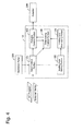
- the control device 18 includes an input control portion 101, an actuator control portion 102, a limiting area setting portion 103, a limiting area memorizing portion 104 and a determining control portion 105.
- the input control portion 101 inputs an NC program by operation of a worker, obtains information memorized in an external media and obtains operation of the worker on an operation panel 300.
- the actuator control portion 102 controls an actuator 200 such as motor based on the NC program inputted by the input control portion 101. For example, when the workpiece W is machined by the grinding wheel 15, the actuator control portion 102 controls the grinding head 14 to move in the Xa direction and the Za direction upon the instructions of the NC program. In this case, the actuator control portion 102 controls the motor which operates the grinding head 14.
- the actuator control portion 102 controls the truing device 17 to move in the Xb direction and the Za direction upon the instructions of the NC program.
- the actuator control portion 102 controls the motor which operates the truing device 17.
- the actuator control portion 102 controls the speed of the mobile body to be slowed down.
- the limiting area setting portion 103 sets the first and the second operation limiting areas Ar (Xa-Za) and Ar (Xb-Zb) shown in Figs. 1 through 3 ,
- the limiting area setting portion 103 sets the first and the second operation limiting areas Ar (Xa-Za) and Ar (Xb-Zb) based on the information relating to the limiting area inputted by the input control portion 101.
- the detail of the limiting area setting portion 103 will be explained later.
- the limiting area memorizing portion 104 memorizes the first and the second operation limiting areas Ar (Xa-Za) and Ar (Xb-Zb) which are set by the limiting area setting portion 103. It is noted however, that the first and the second operation limiting areas Ar (Xa-Za) and Ar (Xb-Zb) which are memorized in the limiting area memorizing portion 104 are the coordinate systems set as indicated in Figs. 2 and 3 and the coordinate of the vertices of the coordinate systems.
- the determining control portion 105 determines whether an operation should be limited or not when an operation limiting invalidation signal is OFF at the manual operation mode or the automated operation mode. When the determining control portion 105 determines that the operation should be limited, the determining control portion 105 controls the actuator control portion 102 to slow down the speed of the mobile body. The operation limiting invalidation signal is obtained by the input control portion 101. The detail of the determining control portion 105 will be explained later.
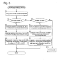
- the limiting area setting portion 103 designates the axes of the coordinate system for the operation limiting area (step S1) (corresponding to the drive axis designating means according to the invention). For example, when the first operation limiting area Ar (Xa-Za) as shown in Fig.1 and Fig. 2 is set, the two axes, the axis Xa and the axis Za are designated.
- the drive axes to be designated are inputted by a worker from the operation panel 300 in advance or may be inputted using the drive axes memorized in the external media. Further, such drive axes can be described in the NC program.
- step S2 whether the number of the designated axes is "two (2)" or not is determined (at the step S2). If the number thereof is determined not to be “two”, whether the number of the designated axis is three (3)" or not is determined (S6). If not the “three” (S6: N), the setting process is invalidated and the process ends (S10). It is noted however, that at the step S6, if the number of designated axis is not "three", the program may return to the step S1 to again designate the number of the axes at the step S1.
- the two-dimensional coordinate system (A - B) is formed and the reference coordinate (A0, B0) in the two-dimensional coordinate system (A - B) is designated (S3) (corresponding to the coordinate system forming means according to the invention).
- the coordinate system in Fig. 2 is indicated as the two-dimensional coordinate system (Xa - Za) and the reference coordinate thereof is (Xa0, Za0).
- Inputting of the reference coordinates (A0, B0) can be made by either one of NC program, external media and the operation panel 300.
- the differences ⁇ A, ⁇ B from the reference coordinate (A0, B0) are designated (S4).
- the difference in the Xa axis direction is designated as ⁇ Xa and the difference in the Za axis direction is ⁇ Za.
- the reference coordinates (A0, B0) and the differences ⁇ A, ⁇ B may be designated by activating the NC program in order to facilitate the inputting work by the worker.
- the four vertex coordinates of the rectangular operation limiting area Ar are calculated based on the reference coordinate (A0, B0) and the differences ⁇ A, ⁇ B and are memorized in the limiting area memorizing portion 104 (S5) (corresponding to the limiting area setting means according to the invention).
- the four vertexes of the operation limiting area Ar (Xa-Za) are designated as four coordinates (Xa0, Za0), (Xa1, Za1), (Xa2, Za2) and (Xa3, Za3).
- the three-dimensional coordinate system (D - E - F) is formed and the reference coordinate (D0, E0, F0) in the three-dimensional coordinate system (D - E - F) is designated (S7) (corresponding to the coordinate system forming means according to the invention).
- S7 the three-dimensional coordinate system forming means according to the invention.
- S8 the differences ⁇ D, ⁇ E, ⁇ F from the reference coordinate (D0, E0, F0) in the coordinate axes.
- the difference in the D-axis direction is designated as ⁇ D
- the difference in the E-axis direction is ⁇ E
- the difference in the F-axis direction is ⁇ F.
- the eight vertex coordinates of the rectangular parallelepiped operation limiting area Ar are calculated based on the reference coordinates(D0, E0, F0) and the differences ⁇ D, ⁇ E ⁇ F and are memorized in the limiting area memorizing portion 104 (S9) (corresponding to the limiting area setting means according to the invention).
- the vertexes of the operation limiting area Ar are designated as eight coordinates (D0, E0, F0), (D1, E1, F1), (D2, E2, F2), (D3, E3, F3), (D4, E4, F4), (D5, E5, F5), (D6, E6, F6), and (D7, E7, F7).
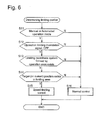
- the operation limiting control portion 105 determines whether the operation mode is in manual operation mode or in automated operation mode (S11) (Corresponding to the determining means according to the invention).
- the manual operation mode includes a handle operation mode and the inching operation mode.
- the handle operation mode means the mode in which a handle provided at the operation panel 300 is, for example, rotated to move the designated mobile body in the designated axial direction.
- setting of the magnification of the handle operation can be possible and accordingly, the mobile body can be moved with a speed corresponding to the set value of the magnified ratio of the handle operation.
- the inching operation mode means the mode in which an inching button which is provided at the operation panel 300 is pushed down to move the designated mobile body in the designated axial direction. The worker can set an overriding of the inching speed by operating the operation panel 300.
- step S11 whether the operation limiting invalidation signal is OFF or not is determined (S12) when the mode is under the manual operation mode or the automated operation mode (S11: Y).
- S12 the operation limiting invalidation signal is set to be OFF where the operation limiting is to be performed.
- An ON/OFF switching-over control of the operation limiting invalidation signal can be freely made by a worker using the operation panel 300 (See Fig. 4 ).
- step S12 when the operation limiting invalidation signal is determined to be OFF (S12: Y), whether a coordinate system formed by drive axis which is going to operate to move the mobile body towards the target position or the drive axis which is currently operating (these axes are called hereinafter as an "operating axis") exists among the coordinate systems memorized in the limiting area memorizing portion 104 or not is determined (S13).
- a coordinate system formed by drive axis which is going to operate to move the mobile body towards the target position or the drive axis which is currently operating (these axes are called hereinafter as an "operating axis" exists among the coordinate systems memorized in the limiting area memorizing portion 104 or not is determined (S13).
- the operating axis corresponds to the Xa axis
- a two-dimensional coordinate system Xa - Za
- an appropriate coordinate system is determined to be existing (S13: Y), then whether the target position or the current position of the subject position P of the mobile body exists in the operation limiting area or not is determined (S14). For example, as shown in Fig. 1 , the grinding point P (Xa-Za) of the grinding wheel which corresponds to the subject point P is in the operation limiting area Ar (Xa-Za) or not is determined.
- the speed limiting control is performed (S15). (Corresponding to the limiting means according to the invention).
- a normal control is performed (S16).
- the normal control means a control that the speed limiting control at the step S15 is not operated.
- step S12 when the operation limiting invalidation signal is changed to ON by the operation of a worker, the normal control is performed as explained above.
- the operation limiting validation signal keeps ON state, no speed limiting control is performed and normal control is performed.
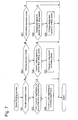
- the speed limiting control will be explained hereinafter, with reference to Fig. 7 .
- the mode for performing the speed limiting control from the step S11 in Fig. 6 is in the handle operation mode, the inching operation mode or the automated operation mode.
- the mode is the handle operation mode (S21: Y)
- whether the current handle magnification is greater than a predetermined limiting magnification or not is determined. (S22). If determination is satisfied (Yes), the handle magnification is changed to the limiting magnification. In other words, thereafter, the mobile body is operated under the limiting magnification set lower than the handle magnification. It is noted that the limiting magnification is set to be a value lower than the magnification normally set, but not including zero.
- the mode is in the inching operation mode (S21: N, S24: Y)
- whether the currently set inching speed is greater than a predetermined limiting speed or not is determined (S25). If determination is satisfied (Yes), the inching speed is changed to the limiting speed. In other words, thereafter, the mobile body is operated under the limiting speed set lower than the inching speed. It is noted that the limiting speed is set to be a value lower than normally set, but not including zero.
- the mode is in the automated operation mode (S24: N, S27: Y)
- whether the target speed or a current designated speed is greater than a predetermined limiting speed or not is determined (S28). If judgment is satisfied (Yes), the designated speed is changed to the limiting speed. In other words, thereafter, the mobile body is operated under the limiting speed set lower than the designated speed. It is noted that the limiting speed is set to be a value lower than normally set, but not including zero.
- the mode for operation limiting is applied in the manual operation mode or the automated operation mode.
- the operation is performed by a worker and therefore, the worker naturally stays in the vicinity of the machine tool.
- the automated operation mode the operation is performed under the worker staying in the vicinity of the machine tool, confirming the operation.
- the mobile body is not stopped but the speed thereof is slowed down. Accordingly, the operation limiting area Ar can be set with a relatively a large clearance distance. In other words, it is not necessary to set the operation limiting area Ar at a borderline position of whether or not for the mobile body to interfere with the object and therefore setting can be easily made. Further, if the mobile body should enter into the operation limiting area by a setting error or the like, the speed of the mobile body is slowed down and accordingly a worker can recognize such speed change of the mobile body to let the worker know the possibility of existing of setting error
- the speed of the mobile body is limited and therefore, a worker can determine whether the program data is wrong or not and if the worker judges that the program data is incorrect, the machine operation can be stopped, for example, by an emergency button being pushed by the worker while the speed of the mobile body is decreased.
- the worker can surely observe the limited operation of the mobile body. It is noted that the emergency stopping operation of the machine is performed separately from the processing of the operation limiting determining and the operation limiting control processing.
- the speed of the mobile body is slowed down not to stop the movement of the mobile body.
- the method is not limited to this embodiment but can be stopping the mobile body. Such stopping of the mobile body would not obtain the effects which are obtained by not stopping the mobile body.
Landscapes
- Engineering & Computer Science (AREA)
- Human Computer Interaction (AREA)
- Manufacturing & Machinery (AREA)
- Physics & Mathematics (AREA)
- General Physics & Mathematics (AREA)
- Automation & Control Theory (AREA)
- Numerical Control (AREA)
- Automatic Control Of Machine Tools (AREA)
Abstract
Description
- The present invention relates to an operation limiting device for a machine tool.
- In the machine tool, in order to prevent the tool from interfering with other parts, the operation of the tool may be limited. For example,
JP Patent Publication No. 60-160407 JP Patent Publication No. 2008-234295 - Further, according to
JP H4-71202 B2 - However, in order to have a wide variety of functions, a machine tool having a number of drive axes has been proposed. For example, there exists a drive axis used exclusively for truing a tool in addition to a drive axis used for moving the tool. Therefore, depending on the type of the mobile body and the type of the drive axis by which the mobile body is driven, condition of the interference state is different. Further, when the mobile body is operated by a plurality of drive axes, even the maximum and minimum values of operation limiting area relative to one of the plurality of the drive axes can be set, such limiting area is not considered to be appropriately set.
- The present invention has been made in consideration with the above issues and the object of the invention is to provide an operation limiting device for a machine tool which is applicable to a wide variety of machine tools and yet which improves the degree of freedom in setting the operation limiting region therefor.
- (Claim 1) The present invention is characterized in that the operation limiting device for a machine tool includes a drive axis designating means for designating two or three drive axes in different directions among a plurality of drive axes, a coordinate system forming means for forming a two-dimensional coordinate system or a three-dimensional coordinate system by the designated two or three drive axes, a limiting area setting means for setting a limiting area to limit an operation of a mobile body in the two-dimensional coordinate system or the three-dimensional coordinate system, a determining means for determining a drive axis by which the mobile body is in operation and a limiting means for limiting the operation of the mobile body when the mobile body enters into the limiting area in the two-dimensional coordinate system or the three-dimensional coordinate system including the drive axis by which the mobile body is in operation.
- According to this structure of the invention, two or three drive axes in different directions among a plurality of drive axes are designated and an area where the operation of the mobile body is limited in the two-dimensional coordinate system or the three-dimensional coordinate system including the designated drive axis. Accordingly, the degree of freedom of setting the operation limiting area can be highly improved. Further, the operation limiting area can be set according to the drive axes even for the machine tool having various types of the drive axes and accordingly, the operation limiting area can be surely and appropriately set.
- (
Claims 2 and 5) Preferably, the determining means determines the drive axis by which the mobile body is in operation in a manual operation mode and the limiting means limits the operation of the mobile body in the manual operation mode. - Further, preferably, the determining means determines the drive axis by which the mobile body is in operation in an automated operation mode and the limiting means limits the operation of the mobile body in the automated operation mode.
- The applicable operation mode is either the manual operation mode or the automated operation mode. At the manual operation mode, a worker operates the machine tool and accordingly, the worker is naturally stays in the vicinity of the machine tool for operation thereof and at the automated operation mode, the worker operates the machine tool staying in the vicinity of the machine tool for confirmation of the operation. Accordingly, the worker can operate by observing the operation of the machine tool at the above operation mode. Thus, by applying the above modes, an interference caused by a careless mistake (mistakes such as, in data setting, in handle magnification selection or in override setting) can be avoided.
- (
Claims 3 and 4) Preferably, the limiting means changes a handle magnification to a limited magnification at a handle operation mode of the manual operation mode. Further, preferably, the limiting means changes an inching speed to a limited speed at an inching motion operation mode of the manual operation mode. - (Claim 6) Further, preferably, the limiting means changes a designated speed to a limited speed.
- (Claim 7) Still further, preferably, the limiting means slows down a speed of the mobile body without stopping thereof when the mobile body enters into the limiting area. As one method of limiting the operation, the mobile body is not stopped but the speed thereof is slowed down. Accordingly, the operation limiting area can be set with a relatively large clearance distance. In other words, it is not necessary to severely set the operation limiting area at a borderline position of whether or not to interfere and therefore setting can be easily made. Further, if the mobile body should enter into the operation limiting area by a setting error or the like, the speed of the mobile body is slowed down and accordingly a worker can recognize such speed change of the mobile body to let the worker recognize the possibility of existing of setting error.
- Particularly, during the manual operation mode, sometimes it may be desired to have the mobile body operate until to a position close to an object or have the mobile body to be in contact with the object. Under such situation it is preferable to have the mobile body to be in operable state. However, a heavy collision between the object and the mobile body should be avoided. Such request can be responded by adapting this method.
- Particularly, during the automated operation mode, when the mobile body enters into the operation limiting area, the speed of the mobile body is limited and therefore, a worker can determine whether the program data is incorrect or not and if determined to be incorrect, the machine operation can be stopped. On the other hand, if determined that the program data is correct and that the mobile body is operated properly within the operation limiting area, the worker can surely observe the limited operation of the mobile body.
- (Claims 8 and 9) In this case, it is preferable that the limiting means slows down the speed of the mobile body without stopping thereof when a target position of the mobile body is in the limiting area. Further, it is preferable that the limiting means slows down the speed of the mobile body without stopping thereof when a current position of the mobile body is in the limiting area.
-
-
Fig. 1 is a plain view of a grinding machine according to an embodiment of the invention: -
Fig. 2 is a detail explanation view of a first operation limiting area inFig. 1 : -
Fig. 3 is a detail explanation view of a second operation limiting area inFig. 1 : -
Fig. 4 is a block diagram of a control device inFig. 1 : -
Fig. 5 is a flowchart showing a process of a limiting area setting processing portion ofFig. 4 : -
Fig. 6 is a flowchart of a process of a determining limiting portion inFig. 4 : -
Fig. 7 is a flowchart of a speed limiting process inFig. 6 : and -
Fig. 8 is a view indicating an operation limiting area of a three-dimensional coordinate system at the steps S7 through S9 inFig. 5 . - As an example of a grinding machine according to the embodiment a grinding head traverse type grinding machine will be explained. However, it is noted that the invention is not limited to the grinding head traverse type grinding machine, but any other type grinding machine can be applicable and any machine tool other than the grinding machine can be applicable.
- The grinding tool according to the embodiment will be explained with reference to
Fig. 1 . As shown inFig. 1 , the grinding machine 1 includes abed 11 fixed on a floor and amain spindle 12 and atailstock device 13 which rotatably support a workpiece W fixed to thebed 11 at both sides. Further, the grinding machine 1 includes a grindinghead 14 movable on thebed 11 in a Z-axis (Za) direction and an X-axis (Xa) direction, a grindingwheel 15 rotatably supported by the grindinghead 14 and asizing device 16 which measures a diameter of the workpiece W. - Still further, the grinding machine 1 includes a
truing device 17 which is movable on the grindinghead 14 in a Z-axis (Zb) direction and an X-axis (b) direction. Thetruing device 17 is used for forming the grindingwheel 15. Further, the grinding machine 1 is provided with acontrol device 18 which controls rotation of themain spindle 12 and the grindingwheel 15 and at the same time, controls position of thegrinding wheel 15 relative to the workpiece W and further controls thetruing device 17. It is noted that the operation limiting device according to the invention corresponds to thecontrol device 18. - In the grinding machine 1, as indicated by the broken line in
FIG 1 , the operation limiting areas Ar(Xa-Za) and Ar(Xb-Zb) are set. Detailed operation limiting areas Ar(Xa-Za) and Ar(Xb-Zb) will be explained with reference toFigs. 2 and 3 . - The first operation limiting area Ar(Xa-Za) defines the interference between the
grinding wheel 15 and the workpiece W. In other words, as shown inFig. 1 , the first operation limiting area Ar (Xa-Za) indicates a limiting area of a grinding point P(Xa-Za) of thegrinding wheel 15 relative to the workpiece W. - The
grinding wheel 15 is operated by the drive axis in the Xa direction and the drive axis in the Za direction. Accordingly, the first operation limiting area Ar(Xa-Za) is formed to be a rectangular shaped area in the two-dimensional coordinate system formed by the Xa direction and the Za direction as shown inFig. 1 . In other words, the coordinate system of the first operation limiting area Ar(Xa-Za) indicates a two-dimensional coordinate system formed by the direction of movement of thegrinding wheel 15 relative to the workpiece W defined as a reference. - As shown in
Fig. 2 , the first operation limiting area Ar(Xa-Za) is enclosed by a reference point (Xa0, Za0), a first vertex (Xa1, Za1) which is separated from the reference point (Xa0, Za0) by ΔXa in an Xa direction, a second vertex (Xa2, Za2) which is separated from the reference point (Xa0, Za0) by ΔXa in Za direction and a third vertex (Xa3, Za3) which is separated from the second vertex (Xa2, Za2) by ΔXa in the Xa direction to form a rectangular shape thereby. - The second operation limiting area Ar(Xb-Zb) defines the interference between the
tooling device 17 and thegrinding wheel 15. In other words, as shown inFig. 1 , the second operation limiting area Ar(Xb-Zb) indicates a limiting area of an end point P(Xb-Zb) of thetruing device 17 relative to thegrinding wheel 15. - The truing
device 17 is operated by the drive axis in the Xb direction and the drive axis in the Zb direction. Accordingly, the second operation limiting area Ar(Xb-Zb) is formed to be a rectangular shape area in the two-dimensional coordinate system formed by the Xb direction and the Zb direction as shown inFig. 1 . In other words, the coordinate system of the second operation limiting area Ar (Xb-Zb) indicates a two-dimensional coordinate system formed by the direction of movement of thetruing device 17 relative to thegrinding wheel 15 defined as a reference. - As shown in
Fig. 3 , the second operation limiting area Ar(Xb-Zb) is enclosed by a reference point (Xb0, Zb0), a first vertex (Xb1, Zb1) which is separated from the reference point (Xa0, Za0) by ΔXb in an Xb direction, a second vertex (Xb2, Zb2) which is separated from the reference point (Xb0, Zb0) by ΔXb in Zb direction and a third vertex (Xb3, Zb3) which is separated from the second vertex (Xb2, Zb2) by ΔXb in the Xb direction to form a rectangular shape thereby. - Next, the functional block diagram for the
control device 18 will be explained with reference toFig. 4 . As shown inFig. 4 , thecontrol device 18 includes aninput control portion 101, anactuator control portion 102, a limitingarea setting portion 103, a limitingarea memorizing portion 104 and a determiningcontrol portion 105. - The
input control portion 101 inputs an NC program by operation of a worker, obtains information memorized in an external media and obtains operation of the worker on anoperation panel 300. - The
actuator control portion 102 controls anactuator 200 such as motor based on the NC program inputted by theinput control portion 101. For example, when the workpiece W is machined by the grindingwheel 15, theactuator control portion 102 controls the grindinghead 14 to move in the Xa direction and the Za direction upon the instructions of the NC program. In this case, theactuator control portion 102 controls the motor which operates the grindinghead 14. - Further, when the grinding
wheel 15 is formed by operating thetruing device 17, theactuator control portion 102 controls the truingdevice 17 to move in the Xb direction and the Za direction upon the instructions of the NC program. In this case, theactuator control portion 102 controls the motor which operates the truingdevice 17. Further, when the operation is limited by the determiningcontrol portion 105, theactuator control portion 102 controls the speed of the mobile body to be slowed down. - The limiting
area setting portion 103 sets the first and the second operation limiting areas Ar(Xa-Za) and Ar(Xb-Zb) shown inFigs. 1 through 3 , The limitingarea setting portion 103 sets the first and the second operation limiting areas Ar(Xa-Za) and Ar(Xb-Zb) based on the information relating to the limiting area inputted by theinput control portion 101. The detail of the limitingarea setting portion 103 will be explained later. - The limiting
area memorizing portion 104 memorizes the first and the second operation limiting areas Ar(Xa-Za) and Ar(Xb-Zb) which are set by the limitingarea setting portion 103. It is noted however, that the first and the second operation limiting areas Ar(Xa-Za) and Ar(Xb-Zb) which are memorized in the limitingarea memorizing portion 104 are the coordinate systems set as indicated inFigs. 2 and 3 and the coordinate of the vertices of the coordinate systems. - The determining
control portion 105 determines whether an operation should be limited or not when an operation limiting invalidation signal is OFF at the manual operation mode or the automated operation mode. When the determiningcontrol portion 105 determines that the operation should be limited, the determiningcontrol portion 105 controls theactuator control portion 102 to slow down the speed of the mobile body. The operation limiting invalidation signal is obtained by theinput control portion 101. The detail of the determiningcontrol portion 105 will be explained later. - The processing for setting the operation limiting area by the limiting
area setting portion 103 will be explained with reference toFig. 5 . As shown inFig. 5 , the limitingarea setting portion 103 designates the axes of the coordinate system for the operation limiting area (step S1) (corresponding to the drive axis designating means according to the invention). For example, when the first operation limiting area Ar(Xa-Za) as shown inFig.1 and Fig. 2 is set, the two axes, the axis Xa and the axis Za are designated. The drive axes to be designated are inputted by a worker from theoperation panel 300 in advance or may be inputted using the drive axes memorized in the external media. Further, such drive axes can be described in the NC program. - Then, whether the number of the designated axes is "two (2)" or not is determined (at the step S2). If the number thereof is determined not to be "two", whether the number of the designated axis is three (3)" or not is determined (S6). If not the "three" (S6: N), the setting process is invalidated and the process ends (S10). It is noted however, that at the step S6, if the number of designated axis is not "three", the program may return to the step S1 to again designate the number of the axes at the step S1.
- At the step S2, when the number of designated axes is determined to be the "two" (S2: Y), the two-dimensional coordinate system (A - B) is formed and the reference coordinate (A0, B0) in the two-dimensional coordinate system (A - B) is designated (S3) (corresponding to the coordinate system forming means according to the invention). The coordinate system in
Fig. 2 is indicated as the two-dimensional coordinate system (Xa - Za) and the reference coordinate thereof is (Xa0, Za0). Inputting of the reference coordinates (A0, B0) can be made by either one of NC program, external media and theoperation panel 300. - Next, the differences ΔA, ΔB from the reference coordinate (A0, B0) are designated (S4). In
Fig. 2 , the difference in the Xa axis direction is designated as ΔXa and the difference in the Za axis direction is ΔZa. Inputting of the differences ΔA, ΔB may be made similarly as explained above. Further, when the workpiece W is changed, the reference coordinates (A0, B0) and the differences ΔA, ΔB may be designated by activating the NC program in order to facilitate the inputting work by the worker. - Then, the four vertex coordinates of the rectangular operation limiting area Ar are calculated based on the reference coordinate (A0, B0) and the differences ΔA, ΔB and are memorized in the limiting area memorizing portion 104 (S5) (corresponding to the limiting area setting means according to the invention). In
Fig. 2 , the four vertexes of the operation limiting area Ar(Xa-Za) are designated as four coordinates (Xa0, Za0), (Xa1, Za1), (Xa2, Za2) and (Xa3, Za3). - On the other hand, at the step S6, when the number of the designated axes is judged to be "three" (S6: Y), the three-dimensional coordinate system (D - E - F) is formed and the reference coordinate (D0, E0, F0) in the three-dimensional coordinate system (D - E - F) is designated (S7) (corresponding to the coordinate system forming means according to the invention). This will be explained, for example, with reference to
Fig. 8 . Next, the differences ΔD, ΔE, ΔF from the reference coordinate (D0, E0, F0) in the coordinate axes are designated (S8). InFig. 8 , the difference in the D-axis direction is designated as ΔD, the difference in the E-axis direction is ΔE and the difference in the F-axis direction is ΔF. - Then, the eight vertex coordinates of the rectangular parallelepiped operation limiting area Ar are calculated based on the reference coordinates(D0, E0, F0) and the differences ΔD, ΔE ΔF and are memorized in the limiting area memorizing portion 104 (S9) (corresponding to the limiting area setting means according to the invention). In
Fig. 8 , the vertexes of the operation limiting area Ar(D-E -F) are designated as eight coordinates (D0, E0, F0), (D1, E1, F1), (D2, E2, F2), (D3, E3, F3), (D4, E4, F4), (D5, E5, F5), (D6, E6, F6), and (D7, E7, F7). - Thus, two or three drive axes in different directions among the plurality of the drive axes are designated and the area in which the operation of the mobile body is limited in the two-dimensional coordinate system or the three-dimensional coordinate system including the designated drive axes are set. Accordingly, the freedom of design for setting the operation limiting area can be highly improved. Further, as explained above, even in a machine tool which includes a wide variety of drive axes including such as Xb axis and Zb axis which move the
truing device 17 other than the axes such as Xa axis and Za axis which move the grindinghead 14, an operation limiting area according to the type of drive axes can be set to achieve a sure and proper setting of the operation limiting area. - Next, the operation limiting determining and the operation limiting control processing by the operation limiting
control portion 105 inFig. 4 will be explained with reference toFigs. 6 and7 . The operation limitingcontrol portion 105 determines whether the operation mode is in manual operation mode or in automated operation mode (S11) (Corresponding to the determining means according to the invention). - The manual operation mode includes a handle operation mode and the inching operation mode. The handle operation mode means the mode in which a handle provided at the
operation panel 300 is, for example, rotated to move the designated mobile body in the designated axial direction. In this handle operation mode, setting of the magnification of the handle operation can be possible and accordingly, the mobile body can be moved with a speed corresponding to the set value of the magnified ratio of the handle operation. - The inching operation mode means the mode in which an inching button which is provided at the
operation panel 300 is pushed down to move the designated mobile body in the designated axial direction. The worker can set an overriding of the inching speed by operating theoperation panel 300. - Next, at the step S11, whether the operation limiting invalidation signal is OFF or not is determined (S12) when the mode is under the manual operation mode or the automated operation mode (S11: Y). At the initial setting of the operation limiting invalidation signal is set to be OFF where the operation limiting is to be performed. An ON/OFF switching-over control of the operation limiting invalidation signal can be freely made by a worker using the operation panel 300 (See
Fig. 4 ). - Next, at the step S12, when the operation limiting invalidation signal is determined to be OFF (S12: Y), whether a coordinate system formed by drive axis which is going to operate to move the mobile body towards the target position or the drive axis which is currently operating (these axes are called hereinafter as an "operating axis") exists among the coordinate systems memorized in the limiting
area memorizing portion 104 or not is determined (S13). (Corresponding to the determining means according to the invention). For example, when the operating axis corresponds to the Xa axis, a two-dimensional coordinate system (Xa - Za) exists. - Next, at the step S13, an appropriate coordinate system is determined to be existing (S13: Y), then whether the target position or the current position of the subject position P of the mobile body exists in the operation limiting area or not is determined (S14). For example, as shown in
Fig. 1 , the grinding point P(Xa-Za) of the grinding wheel which corresponds to the subject point P is in the operation limiting area Ar(Xa-Za) or not is determined. - Next, when the condition of the step S14 is satisfied, the speed limiting control is performed (S15). (Corresponding to the limiting means according to the invention). On the other hand, when the conditions of the steps S11 through S14 are not satisfied, a normal control is performed (S16). The normal control means a control that the speed limiting control at the step S15 is not operated.
- It is noted here that at the step S12, when the operation limiting invalidation signal is changed to ON by the operation of a worker, the normal control is performed as explained above. When a correct normal operation is confirmed during the normal controlling, it is possible to keep the operation limiting validation signal to be ON. While the operation limiting validation signal keeps ON state, no speed limiting control is performed and normal control is performed.
- The speed limiting control will be explained hereinafter, with reference to
Fig. 7 . The mode for performing the speed limiting control from the step S11 inFig. 6 is in the handle operation mode, the inching operation mode or the automated operation mode. - As shown in
Fig. 7 , when the mode is the handle operation mode (S21: Y), whether the current handle magnification is greater than a predetermined limiting magnification or not is determined. (S22). If determination is satisfied (Yes), the handle magnification is changed to the limiting magnification. In other words, thereafter, the mobile body is operated under the limiting magnification set lower than the handle magnification. It is noted that the limiting magnification is set to be a value lower than the magnification normally set, but not including zero. - When the mode is in the inching operation mode (S21: N, S24: Y), whether the currently set inching speed is greater than a predetermined limiting speed or not is determined (S25). If determination is satisfied (Yes), the inching speed is changed to the limiting speed. In other words, thereafter, the mobile body is operated under the limiting speed set lower than the inching speed. It is noted that the limiting speed is set to be a value lower than normally set, but not including zero.
- When the mode is in the automated operation mode (S24: N, S27: Y), whether the target speed or a current designated speed is greater than a predetermined limiting speed or not is determined (S28). If judgment is satisfied (Yes), the designated speed is changed to the limiting speed. In other words, thereafter, the mobile body is operated under the limiting speed set lower than the designated speed. It is noted that the limiting speed is set to be a value lower than normally set, but not including zero.
- As explained above, the mode for operation limiting is applied in the manual operation mode or the automated operation mode. In the manual operation mode, the operation is performed by a worker and therefore, the worker naturally stays in the vicinity of the machine tool. At the automated operation mode, the operation is performed under the worker staying in the vicinity of the machine tool, confirming the operation. Thus, by applying the operation limiting to the above modes, an interference caused by a careless mistake (mistakes such as, in data setting, in handle magnification selection or in override setting) can be avoided.
- As one method of limiting the operation, the mobile body is not stopped but the speed thereof is slowed down. Accordingly, the operation limiting area Ar can be set with a relatively a large clearance distance. In other words, it is not necessary to set the operation limiting area Ar at a borderline position of whether or not for the mobile body to interfere with the object and therefore setting can be easily made. Further, if the mobile body should enter into the operation limiting area by a setting error or the like, the speed of the mobile body is slowed down and accordingly a worker can recognize such speed change of the mobile body to let the worker know the possibility of existing of setting error
- Further, particularly, during the manual operation mode, sometimes it may be desired to have the mobile body operate until to a position close to an object or have the mobile body to be in contact with the object. Under such situation it is preferable to have the mobile body to be in operable state. However, a heavy collision between the object and the mobile body should be avoided. Such request can be responded by adapting this method according to the embodiment.
- Particularly, during the automated operation mode, when the mobile body enters into the operation limiting area, the speed of the mobile body is limited and therefore, a worker can determine whether the program data is wrong or not and if the worker judges that the program data is incorrect, the machine operation can be stopped, for example, by an emergency button being pushed by the worker while the speed of the mobile body is decreased. On the other hand, if determined that the program data is correct and that the mobile body is operated properly within the operation limiting area, the worker can surely observe the limited operation of the mobile body. It is noted that the emergency stopping operation of the machine is performed separately from the processing of the operation limiting determining and the operation limiting control processing.
- According to the embodiment, as one of the operation limiting methods, the speed of the mobile body is slowed down not to stop the movement of the mobile body. However, the method is not limited to this embodiment but can be stopping the mobile body. Such stopping of the mobile body would not obtain the effects which are obtained by not stopping the mobile body.
- In the drawings:
- 1: grinding machine (machine tool), 14:grinding head, 15: grinding wheel (mobile body), 17:truing device (mobile body), 18: control device, 103: limiting area setting portion (drive axis designating means, coordinate system forming means, limiting area setting means), 105: determining control portion (determining means, limiting means), Ar(Xa-Za), Ar(Xb-Zb), Ar(D-E-F): operation limiting area, W: workpiece, Xa, Za, Xb, Zb: drive axes, (Xa-Zb), (Xb-Zb): 2-dimensional coordinate system, (D-E-F): 3-dimensional coordinate system.
Claims (9)
- An operation limiting device for a machine tool comprising:a drive axis designating means for designating two or three drive axes in different directions among a plurality of drive axes of the machine tool;a coordinate system forming means for forming a two-dimensional coordinate system or a three-dimensional coordinate system by the designated two or three drive axes;a limiting area setting means for setting a limiting area to limit an operation of a mobile body in the two-dimensional coordinate system or the three-dimensional coordinate system;a determining means for determining a drive axis by which the mobile body is in operation; anda limiting means for limiting the operation of the mobile body when the mobile body enters into the limiting area in the two-dimensional coordinate system or the three-dimensional coordinate system including the drive axis by which the mobile body is in operation.
- The operation limiting device for a machine tool according to claim 1, wherein the determining means determines the drive axis by which the mobile body is in operation in a manual operation mode and the limiting means limits the operation of the mobile body in the manual operation mode.
- The operation limiting device for a machine tool according to claim 2, wherein the limiting means changes a handle magnification to a limited magnification at a handle operation mode in the manual operation mode.
- The operation limiting device for a machine tool according to claim 2, wherein the limiting means changes an inching speed to a limited speed at an inching motion operation mode in the manual operation mode.
- The operation limiting device for a machine tool according to any one of claims 1 through 4, wherein the determining means determines the drive axis by which the mobile body is in operation in an automated operation mode and the limiting means limits the operation of the mobile body in the automated operation mode.
- The operation limiting device for a machine tool according to claim 5, wherein the limiting means changes a designated speed to a limited speed.
- The operation limiting device for a machine tool according to any one of claims 2 through 6, wherein the limiting means slows down a speed of the mobile body without stopping thereof when the mobile body enters into the limiting area.
- The operation limiting device for a machine tool according to claim 7, wherein the limiting means slows down the speed of the mobile body without stopping thereof when a target position of the mobile body is in the limiting area.
- The operation limiting device for a machine tool according to claim 7, the limiting means slows down the speed of the mobile body without stopping thereof when a current position of the mobile body is in the limiting area.
Applications Claiming Priority (2)
| Application Number | Priority Date | Filing Date | Title |
|---|---|---|---|
| JP2012239797A JP6102185B2 (en) | 2012-10-31 | 2012-10-31 | Machine tool operation restriction device |
| PCT/JP2013/079523 WO2014069560A1 (en) | 2012-10-31 | 2013-10-31 | Operation limiting device for machine tool |
Publications (3)
| Publication Number | Publication Date |
|---|---|
| EP2916185A1 true EP2916185A1 (en) | 2015-09-09 |
| EP2916185A4 EP2916185A4 (en) | 2016-07-06 |
| EP2916185B1 EP2916185B1 (en) | 2021-09-22 |
Family
ID=50627458
Family Applications (1)
| Application Number | Title | Priority Date | Filing Date |
|---|---|---|---|
| EP13850867.6A Not-in-force EP2916185B1 (en) | 2012-10-31 | 2013-10-31 | Operation limiting device for machine tool |
Country Status (6)
| Country | Link |
|---|---|
| US (1) | US10133253B2 (en) |
| EP (1) | EP2916185B1 (en) |
| JP (1) | JP6102185B2 (en) |
| CN (1) | CN104737083B (en) |
| BR (1) | BR112015007465A2 (en) |
| WO (1) | WO2014069560A1 (en) |
Families Citing this family (4)
| Publication number | Priority date | Publication date | Assignee | Title |
|---|---|---|---|---|
| KR101538536B1 (en) * | 2013-02-18 | 2015-07-22 | 정경순 | Drum washing apparetus |
| JP2015191306A (en) * | 2014-03-27 | 2015-11-02 | オークマ株式会社 | Control method of machine tool, and control device |
| KR102184922B1 (en) * | 2014-12-23 | 2020-12-01 | 두산공작기계 주식회사 | Machine tool |
| CN110976206B (en) * | 2019-11-28 | 2022-08-12 | 深圳市世宗自动化设备有限公司 | Dispensing control method and device, computer equipment and storage medium thereof |
Family Cites Families (14)
| Publication number | Priority date | Publication date | Assignee | Title |
|---|---|---|---|---|
| JPS5624608A (en) * | 1979-08-07 | 1981-03-09 | Fanuc Ltd | Numerical value control system |
| JPS58163001A (en) | 1982-03-23 | 1983-09-27 | Toyoda Mach Works Ltd | Numerical controller equipped with interference checking function |
| US4608643A (en) * | 1983-08-18 | 1986-08-26 | Spiral Step Tool Company | Automatic tool grinding machine with computerized control |
| JPS60160407A (en) | 1984-02-01 | 1985-08-22 | Fanuc Ltd | Numerical controller |
| JPH0716850B2 (en) * | 1987-08-19 | 1995-03-01 | ファナック株式会社 | Axis switching device |
| JPH0471202A (en) | 1990-07-11 | 1992-03-05 | Mitsubishi Electric Corp | Thick film resistor element |
| JPH08152908A (en) * | 1994-11-29 | 1996-06-11 | Mitsubishi Heavy Ind Ltd | Tool moving device for machine tool |
| JPH1094945A (en) * | 1996-09-19 | 1998-04-14 | Fanuc Ltd | Machining limit area designating method and manual machining method in numerical control device |
| JP2005102923A (en) * | 2003-09-30 | 2005-04-21 | Ricoh Elemex Corp | Air purifier |
| JP4456455B2 (en) * | 2004-10-08 | 2010-04-28 | 中村留精密工業株式会社 | Collision prevention method for machine operating part in lathe |
| JP4838647B2 (en) * | 2006-07-05 | 2011-12-14 | 株式会社森精機製作所 | Machine tool controller |
| JP5030628B2 (en) | 2007-03-20 | 2012-09-19 | ファナック株式会社 | Interference check system |
| US8844104B2 (en) * | 2009-04-22 | 2014-09-30 | Hurco Companies, Inc. | Multi-zone machine tool system |
| CN102812406B (en) * | 2010-03-24 | 2015-04-29 | 三菱电机株式会社 | Numerical control device and numerical control method |
-
2012
- 2012-10-31 JP JP2012239797A patent/JP6102185B2/en not_active Expired - Fee Related
-
2013
- 2013-10-31 WO PCT/JP2013/079523 patent/WO2014069560A1/en not_active Ceased
- 2013-10-31 BR BR112015007465A patent/BR112015007465A2/en not_active Application Discontinuation
- 2013-10-31 CN CN201380055026.XA patent/CN104737083B/en not_active Expired - Fee Related
- 2013-10-31 US US14/428,723 patent/US10133253B2/en not_active Expired - Fee Related
- 2013-10-31 EP EP13850867.6A patent/EP2916185B1/en not_active Not-in-force
Also Published As
| Publication number | Publication date |
|---|---|
| JP6102185B2 (en) | 2017-03-29 |
| EP2916185B1 (en) | 2021-09-22 |
| EP2916185A4 (en) | 2016-07-06 |
| US20150248124A1 (en) | 2015-09-03 |
| CN104737083B (en) | 2017-10-13 |
| CN104737083A (en) | 2015-06-24 |
| JP2014089623A (en) | 2014-05-15 |
| US10133253B2 (en) | 2018-11-20 |
| WO2014069560A1 (en) | 2014-05-08 |
| BR112015007465A2 (en) | 2017-07-04 |
Similar Documents
| Publication | Publication Date | Title |
|---|---|---|
| US9507337B2 (en) | Numerical control device | |
| US7012395B2 (en) | Method for continuous-path control | |
| US7847506B2 (en) | Machine tool controller | |
| EP2916185B1 (en) | Operation limiting device for machine tool | |
| JP5471159B2 (en) | Machine tool controller | |
| US9897991B2 (en) | Machine tool | |
| US20100228384A1 (en) | Method and device for generating transformed control data for controlling a tool on a machine tool | |
| WO1999022904A2 (en) | Method and system for computer assisted manual machine tool control | |
| US8712576B2 (en) | Controller for machine tool and five-axis simultaneous control machine tool controlled thereby | |
| US8630732B2 (en) | Method for avoiding an unwanted collision between a tool and a workpiece in a machine tool | |
| WO2010004960A1 (en) | Interference check device, interference check method, and machine tool having the interference check device | |
| JP5079165B2 (en) | Numerical control apparatus and numerical control method | |
| US10558193B2 (en) | Method for machining a workpiece in a machine tool with optimized machining time | |
| EP1508843B1 (en) | Numerical control apparatus | |
| JP4461030B2 (en) | Numerical control apparatus and numerical control method | |
| JP4995976B1 (en) | Numerical control device that performs in-position check of rotating shaft | |
| US20100086374A1 (en) | Dynamically optimized machine tool having superimposed drive systems | |
| CN107664980B (en) | Numerical controller and method for controlling movement of tool | |
| JP2020032484A (en) | Grinding device and control method thereof | |
| KR102789717B1 (en) | Vibration control method for workpiece polishing of NC machine tools | |
| JP2005321890A (en) | Misworking prevention device and misworking prevention method | |
| JP2007505378A (en) | Machining method of workpiece with rotary cutting tool | |
| JP2010102733A (en) | Numerical controller | |
| JP4982170B2 (en) | Machining control device and machining control program | |
| JP2007249671A (en) | Method for preventing collision in machine tool |
Legal Events
| Date | Code | Title | Description |
|---|---|---|---|
| PUAI | Public reference made under article 153(3) epc to a published international application that has entered the european phase |
Free format text: ORIGINAL CODE: 0009012 |
|
| 17P | Request for examination filed |
Effective date: 20150303 |
|
| AK | Designated contracting states |
Kind code of ref document: A1 Designated state(s): AL AT BE BG CH CY CZ DE DK EE ES FI FR GB GR HR HU IE IS IT LI LT LU LV MC MK MT NL NO PL PT RO RS SE SI SK SM TR |
|
| AX | Request for extension of the european patent |
Extension state: BA ME |
|
| DAX | Request for extension of the european patent (deleted) | ||
| RA4 | Supplementary search report drawn up and despatched (corrected) |
Effective date: 20160602 |
|
| RIC1 | Information provided on ipc code assigned before grant |
Ipc: G05B 19/4061 20060101ALI20160527BHEP Ipc: G05B 19/18 20060101AFI20160527BHEP Ipc: B23Q 15/013 20060101ALI20160527BHEP |
|
| STAA | Information on the status of an ep patent application or granted ep patent |
Free format text: STATUS: EXAMINATION IS IN PROGRESS |
|
| 17Q | First examination report despatched |
Effective date: 20180321 |
|
| GRAP | Despatch of communication of intention to grant a patent |
Free format text: ORIGINAL CODE: EPIDOSNIGR1 |
|
| STAA | Information on the status of an ep patent application or granted ep patent |
Free format text: STATUS: GRANT OF PATENT IS INTENDED |
|
| INTG | Intention to grant announced |
Effective date: 20210609 |
|
| GRAS | Grant fee paid |
Free format text: ORIGINAL CODE: EPIDOSNIGR3 |
|
| GRAA | (expected) grant |
Free format text: ORIGINAL CODE: 0009210 |
|
| STAA | Information on the status of an ep patent application or granted ep patent |
Free format text: STATUS: THE PATENT HAS BEEN GRANTED |
|
| AK | Designated contracting states |
Kind code of ref document: B1 Designated state(s): AL AT BE BG CH CY CZ DE DK EE ES FI FR GB GR HR HU IE IS IT LI LT LU LV MC MK MT NL NO PL PT RO RS SE SI SK SM TR |
|
| REG | Reference to a national code |
Ref country code: GB Ref legal event code: FG4D |
|
| REG | Reference to a national code |
Ref country code: DE Ref legal event code: R096 Ref document number: 602013079392 Country of ref document: DE |
|
| REG | Reference to a national code |
Ref country code: IE Ref legal event code: FG4D |
|
| REG | Reference to a national code |
Ref country code: CH Ref legal event code: EP Ref country code: AT Ref legal event code: REF Ref document number: 1432804 Country of ref document: AT Kind code of ref document: T Effective date: 20211015 |
|
| REG | Reference to a national code |
Ref country code: LT Ref legal event code: MG9D |
|
| REG | Reference to a national code |
Ref country code: NL Ref legal event code: MP Effective date: 20210922 |
|
| PG25 | Lapsed in a contracting state [announced via postgrant information from national office to epo] |
Ref country code: HR Free format text: LAPSE BECAUSE OF FAILURE TO SUBMIT A TRANSLATION OF THE DESCRIPTION OR TO PAY THE FEE WITHIN THE PRESCRIBED TIME-LIMIT Effective date: 20210922 Ref country code: RS Free format text: LAPSE BECAUSE OF FAILURE TO SUBMIT A TRANSLATION OF THE DESCRIPTION OR TO PAY THE FEE WITHIN THE PRESCRIBED TIME-LIMIT Effective date: 20210922 Ref country code: SE Free format text: LAPSE BECAUSE OF FAILURE TO SUBMIT A TRANSLATION OF THE DESCRIPTION OR TO PAY THE FEE WITHIN THE PRESCRIBED TIME-LIMIT Effective date: 20210922 Ref country code: BG Free format text: LAPSE BECAUSE OF FAILURE TO SUBMIT A TRANSLATION OF THE DESCRIPTION OR TO PAY THE FEE WITHIN THE PRESCRIBED TIME-LIMIT Effective date: 20211222 Ref country code: LT Free format text: LAPSE BECAUSE OF FAILURE TO SUBMIT A TRANSLATION OF THE DESCRIPTION OR TO PAY THE FEE WITHIN THE PRESCRIBED TIME-LIMIT Effective date: 20210922 Ref country code: NO Free format text: LAPSE BECAUSE OF FAILURE TO SUBMIT A TRANSLATION OF THE DESCRIPTION OR TO PAY THE FEE WITHIN THE PRESCRIBED TIME-LIMIT Effective date: 20211222 Ref country code: FI Free format text: LAPSE BECAUSE OF FAILURE TO SUBMIT A TRANSLATION OF THE DESCRIPTION OR TO PAY THE FEE WITHIN THE PRESCRIBED TIME-LIMIT Effective date: 20210922 |
|
| PGFP | Annual fee paid to national office [announced via postgrant information from national office to epo] |
Ref country code: DE Payment date: 20211028 Year of fee payment: 9 Ref country code: FR Payment date: 20211112 Year of fee payment: 9 |
|
| REG | Reference to a national code |
Ref country code: AT Ref legal event code: MK05 Ref document number: 1432804 Country of ref document: AT Kind code of ref document: T Effective date: 20210922 |
|
| PG25 | Lapsed in a contracting state [announced via postgrant information from national office to epo] |
Ref country code: LV Free format text: LAPSE BECAUSE OF FAILURE TO SUBMIT A TRANSLATION OF THE DESCRIPTION OR TO PAY THE FEE WITHIN THE PRESCRIBED TIME-LIMIT Effective date: 20210922 Ref country code: GR Free format text: LAPSE BECAUSE OF FAILURE TO SUBMIT A TRANSLATION OF THE DESCRIPTION OR TO PAY THE FEE WITHIN THE PRESCRIBED TIME-LIMIT Effective date: 20211223 |
|
| RAP4 | Party data changed (patent owner data changed or rights of a patent transferred) |
Owner name: JTEKT CORPORATION |
|
| PG25 | Lapsed in a contracting state [announced via postgrant information from national office to epo] |
Ref country code: AT Free format text: LAPSE BECAUSE OF FAILURE TO SUBMIT A TRANSLATION OF THE DESCRIPTION OR TO PAY THE FEE WITHIN THE PRESCRIBED TIME-LIMIT Effective date: 20210922 |
|
| REG | Reference to a national code |
Ref country code: CH Ref legal event code: PL |
|
| PG25 | Lapsed in a contracting state [announced via postgrant information from national office to epo] |
Ref country code: IS Free format text: LAPSE BECAUSE OF FAILURE TO SUBMIT A TRANSLATION OF THE DESCRIPTION OR TO PAY THE FEE WITHIN THE PRESCRIBED TIME-LIMIT Effective date: 20220122 Ref country code: SK Free format text: LAPSE BECAUSE OF FAILURE TO SUBMIT A TRANSLATION OF THE DESCRIPTION OR TO PAY THE FEE WITHIN THE PRESCRIBED TIME-LIMIT Effective date: 20210922 Ref country code: RO Free format text: LAPSE BECAUSE OF FAILURE TO SUBMIT A TRANSLATION OF THE DESCRIPTION OR TO PAY THE FEE WITHIN THE PRESCRIBED TIME-LIMIT Effective date: 20210922 Ref country code: PT Free format text: LAPSE BECAUSE OF FAILURE TO SUBMIT A TRANSLATION OF THE DESCRIPTION OR TO PAY THE FEE WITHIN THE PRESCRIBED TIME-LIMIT Effective date: 20220124 Ref country code: PL Free format text: LAPSE BECAUSE OF FAILURE TO SUBMIT A TRANSLATION OF THE DESCRIPTION OR TO PAY THE FEE WITHIN THE PRESCRIBED TIME-LIMIT Effective date: 20210922 Ref country code: NL Free format text: LAPSE BECAUSE OF FAILURE TO SUBMIT A TRANSLATION OF THE DESCRIPTION OR TO PAY THE FEE WITHIN THE PRESCRIBED TIME-LIMIT Effective date: 20210922 Ref country code: ES Free format text: LAPSE BECAUSE OF FAILURE TO SUBMIT A TRANSLATION OF THE DESCRIPTION OR TO PAY THE FEE WITHIN THE PRESCRIBED TIME-LIMIT Effective date: 20210922 Ref country code: EE Free format text: LAPSE BECAUSE OF FAILURE TO SUBMIT A TRANSLATION OF THE DESCRIPTION OR TO PAY THE FEE WITHIN THE PRESCRIBED TIME-LIMIT Effective date: 20210922 Ref country code: CZ Free format text: LAPSE BECAUSE OF FAILURE TO SUBMIT A TRANSLATION OF THE DESCRIPTION OR TO PAY THE FEE WITHIN THE PRESCRIBED TIME-LIMIT Effective date: 20210922 Ref country code: AL Free format text: LAPSE BECAUSE OF FAILURE TO SUBMIT A TRANSLATION OF THE DESCRIPTION OR TO PAY THE FEE WITHIN THE PRESCRIBED TIME-LIMIT Effective date: 20210922 |
|
| REG | Reference to a national code |
Ref country code: DE Ref legal event code: R097 Ref document number: 602013079392 Country of ref document: DE Ref country code: BE Ref legal event code: MM Effective date: 20211031 |
|
| PG25 | Lapsed in a contracting state [announced via postgrant information from national office to epo] |
Ref country code: MC Free format text: LAPSE BECAUSE OF FAILURE TO SUBMIT A TRANSLATION OF THE DESCRIPTION OR TO PAY THE FEE WITHIN THE PRESCRIBED TIME-LIMIT Effective date: 20210922 |
|
| PG25 | Lapsed in a contracting state [announced via postgrant information from national office to epo] |
Ref country code: LU Free format text: LAPSE BECAUSE OF NON-PAYMENT OF DUE FEES Effective date: 20211031 Ref country code: DK Free format text: LAPSE BECAUSE OF FAILURE TO SUBMIT A TRANSLATION OF THE DESCRIPTION OR TO PAY THE FEE WITHIN THE PRESCRIBED TIME-LIMIT Effective date: 20210922 Ref country code: BE Free format text: LAPSE BECAUSE OF NON-PAYMENT OF DUE FEES Effective date: 20211031 |
|
| PLBE | No opposition filed within time limit |
Free format text: ORIGINAL CODE: 0009261 |
|
| STAA | Information on the status of an ep patent application or granted ep patent |
Free format text: STATUS: NO OPPOSITION FILED WITHIN TIME LIMIT |
|
| GBPC | Gb: european patent ceased through non-payment of renewal fee |
Effective date: 20211222 |
|
| 26N | No opposition filed |
Effective date: 20220623 |
|
| PG25 | Lapsed in a contracting state [announced via postgrant information from national office to epo] |
Ref country code: LI Free format text: LAPSE BECAUSE OF NON-PAYMENT OF DUE FEES Effective date: 20211031 Ref country code: CH Free format text: LAPSE BECAUSE OF NON-PAYMENT OF DUE FEES Effective date: 20211031 |
|
| PG25 | Lapsed in a contracting state [announced via postgrant information from national office to epo] |
Ref country code: IE Free format text: LAPSE BECAUSE OF NON-PAYMENT OF DUE FEES Effective date: 20211031 Ref country code: GB Free format text: LAPSE BECAUSE OF NON-PAYMENT OF DUE FEES Effective date: 20211222 |
|
| PG25 | Lapsed in a contracting state [announced via postgrant information from national office to epo] |
Ref country code: SI Free format text: LAPSE BECAUSE OF FAILURE TO SUBMIT A TRANSLATION OF THE DESCRIPTION OR TO PAY THE FEE WITHIN THE PRESCRIBED TIME-LIMIT Effective date: 20210922 |
|
| PG25 | Lapsed in a contracting state [announced via postgrant information from national office to epo] |
Ref country code: IT Free format text: LAPSE BECAUSE OF FAILURE TO SUBMIT A TRANSLATION OF THE DESCRIPTION OR TO PAY THE FEE WITHIN THE PRESCRIBED TIME-LIMIT Effective date: 20210922 |
|
| REG | Reference to a national code |
Ref country code: DE Ref legal event code: R119 Ref document number: 602013079392 Country of ref document: DE |
|
| PG25 | Lapsed in a contracting state [announced via postgrant information from national office to epo] |
Ref country code: HU Free format text: LAPSE BECAUSE OF FAILURE TO SUBMIT A TRANSLATION OF THE DESCRIPTION OR TO PAY THE FEE WITHIN THE PRESCRIBED TIME-LIMIT; INVALID AB INITIO Effective date: 20131031 |
|
| PG25 | Lapsed in a contracting state [announced via postgrant information from national office to epo] |
Ref country code: CY Free format text: LAPSE BECAUSE OF FAILURE TO SUBMIT A TRANSLATION OF THE DESCRIPTION OR TO PAY THE FEE WITHIN THE PRESCRIBED TIME-LIMIT Effective date: 20210922 |
|
| PG25 | Lapsed in a contracting state [announced via postgrant information from national office to epo] |
Ref country code: SM Free format text: LAPSE BECAUSE OF FAILURE TO SUBMIT A TRANSLATION OF THE DESCRIPTION OR TO PAY THE FEE WITHIN THE PRESCRIBED TIME-LIMIT Effective date: 20210922 Ref country code: FR Free format text: LAPSE BECAUSE OF NON-PAYMENT OF DUE FEES Effective date: 20221031 Ref country code: DE Free format text: LAPSE BECAUSE OF NON-PAYMENT OF DUE FEES Effective date: 20230503 |
|
| PG25 | Lapsed in a contracting state [announced via postgrant information from national office to epo] |
Ref country code: MK Free format text: LAPSE BECAUSE OF FAILURE TO SUBMIT A TRANSLATION OF THE DESCRIPTION OR TO PAY THE FEE WITHIN THE PRESCRIBED TIME-LIMIT Effective date: 20210922 |
|
| PG25 | Lapsed in a contracting state [announced via postgrant information from national office to epo] |
Ref country code: MT Free format text: LAPSE BECAUSE OF FAILURE TO SUBMIT A TRANSLATION OF THE DESCRIPTION OR TO PAY THE FEE WITHIN THE PRESCRIBED TIME-LIMIT Effective date: 20210922 |
|
| PG25 | Lapsed in a contracting state [announced via postgrant information from national office to epo] |
Ref country code: TR Free format text: LAPSE BECAUSE OF FAILURE TO SUBMIT A TRANSLATION OF THE DESCRIPTION OR TO PAY THE FEE WITHIN THE PRESCRIBED TIME-LIMIT Effective date: 20210922 |