EP2916144A1 - Antenne mimo avec détection d'élévation - Google Patents
Antenne mimo avec détection d'élévation Download PDFInfo
- Publication number
- EP2916144A1 EP2916144A1 EP15156400.2A EP15156400A EP2916144A1 EP 2916144 A1 EP2916144 A1 EP 2916144A1 EP 15156400 A EP15156400 A EP 15156400A EP 2916144 A1 EP2916144 A1 EP 2916144A1
- Authority
- EP
- European Patent Office
- Prior art keywords
- antenna
- phase
- centers
- transmit
- transmit antenna
- Prior art date
- Legal status (The legal status is an assumption and is not a legal conclusion. Google has not performed a legal analysis and makes no representation as to the accuracy of the status listed.)
- Withdrawn
Links
Images


Classifications
-
- G—PHYSICS
- G01—MEASURING; TESTING
- G01S—RADIO DIRECTION-FINDING; RADIO NAVIGATION; DETERMINING DISTANCE OR VELOCITY BY USE OF RADIO WAVES; LOCATING OR PRESENCE-DETECTING BY USE OF THE REFLECTION OR RERADIATION OF RADIO WAVES; ANALOGOUS ARRANGEMENTS USING OTHER WAVES
- G01S13/00—Systems using the reflection or reradiation of radio waves, e.g. radar systems; Analogous systems using reflection or reradiation of waves whose nature or wavelength is irrelevant or unspecified
- G01S13/02—Systems using reflection of radio waves, e.g. primary radar systems; Analogous systems
- G01S13/06—Systems determining position data of a target
- G01S13/42—Simultaneous measurement of distance and other co-ordinates
- G01S13/44—Monopulse radar, i.e. simultaneous lobing
- G01S13/4454—Monopulse radar, i.e. simultaneous lobing phase comparisons monopulse, i.e. comparing the echo signals received by an interferometric antenna arrangement
-
- G—PHYSICS
- G01—MEASURING; TESTING
- G01S—RADIO DIRECTION-FINDING; RADIO NAVIGATION; DETERMINING DISTANCE OR VELOCITY BY USE OF RADIO WAVES; LOCATING OR PRESENCE-DETECTING BY USE OF THE REFLECTION OR RERADIATION OF RADIO WAVES; ANALOGOUS ARRANGEMENTS USING OTHER WAVES
- G01S13/00—Systems using the reflection or reradiation of radio waves, e.g. radar systems; Analogous systems using reflection or reradiation of waves whose nature or wavelength is irrelevant or unspecified
- G01S13/003—Bistatic radar systems; Multistatic radar systems
-
- G—PHYSICS
- G01—MEASURING; TESTING
- G01S—RADIO DIRECTION-FINDING; RADIO NAVIGATION; DETERMINING DISTANCE OR VELOCITY BY USE OF RADIO WAVES; LOCATING OR PRESENCE-DETECTING BY USE OF THE REFLECTION OR RERADIATION OF RADIO WAVES; ANALOGOUS ARRANGEMENTS USING OTHER WAVES
- G01S13/00—Systems using the reflection or reradiation of radio waves, e.g. radar systems; Analogous systems using reflection or reradiation of waves whose nature or wavelength is irrelevant or unspecified
- G01S13/02—Systems using reflection of radio waves, e.g. primary radar systems; Analogous systems
- G01S13/06—Systems determining position data of a target
- G01S13/42—Simultaneous measurement of distance and other co-ordinates
- G01S13/424—Stacked beam radar
-
- G—PHYSICS
- G01—MEASURING; TESTING
- G01S—RADIO DIRECTION-FINDING; RADIO NAVIGATION; DETERMINING DISTANCE OR VELOCITY BY USE OF RADIO WAVES; LOCATING OR PRESENCE-DETECTING BY USE OF THE REFLECTION OR RERADIATION OF RADIO WAVES; ANALOGOUS ARRANGEMENTS USING OTHER WAVES
- G01S13/00—Systems using the reflection or reradiation of radio waves, e.g. radar systems; Analogous systems using reflection or reradiation of waves whose nature or wavelength is irrelevant or unspecified
- G01S13/88—Radar or analogous systems specially adapted for specific applications
- G01S13/93—Radar or analogous systems specially adapted for specific applications for anti-collision purposes
- G01S13/931—Radar or analogous systems specially adapted for specific applications for anti-collision purposes of land vehicles
-
- G—PHYSICS
- G01—MEASURING; TESTING
- G01S—RADIO DIRECTION-FINDING; RADIO NAVIGATION; DETERMINING DISTANCE OR VELOCITY BY USE OF RADIO WAVES; LOCATING OR PRESENCE-DETECTING BY USE OF THE REFLECTION OR RERADIATION OF RADIO WAVES; ANALOGOUS ARRANGEMENTS USING OTHER WAVES
- G01S7/00—Details of systems according to groups G01S13/00, G01S15/00, G01S17/00
- G01S7/02—Details of systems according to groups G01S13/00, G01S15/00, G01S17/00 of systems according to group G01S13/00
- G01S7/03—Details of HF subsystems specially adapted therefor, e.g. common to transmitter and receiver
-
- G—PHYSICS
- G01—MEASURING; TESTING
- G01S—RADIO DIRECTION-FINDING; RADIO NAVIGATION; DETERMINING DISTANCE OR VELOCITY BY USE OF RADIO WAVES; LOCATING OR PRESENCE-DETECTING BY USE OF THE REFLECTION OR RERADIATION OF RADIO WAVES; ANALOGOUS ARRANGEMENTS USING OTHER WAVES
- G01S7/00—Details of systems according to groups G01S13/00, G01S15/00, G01S17/00
- G01S7/02—Details of systems according to groups G01S13/00, G01S15/00, G01S17/00 of systems according to group G01S13/00
- G01S7/28—Details of pulse systems
- G01S7/2813—Means providing a modification of the radiation pattern for cancelling noise, clutter or interfering signals, e.g. side lobe suppression, side lobe blanking, null-steering arrays
-
- G—PHYSICS
- G01—MEASURING; TESTING
- G01S—RADIO DIRECTION-FINDING; RADIO NAVIGATION; DETERMINING DISTANCE OR VELOCITY BY USE OF RADIO WAVES; LOCATING OR PRESENCE-DETECTING BY USE OF THE REFLECTION OR RERADIATION OF RADIO WAVES; ANALOGOUS ARRANGEMENTS USING OTHER WAVES
- G01S7/00—Details of systems according to groups G01S13/00, G01S15/00, G01S17/00
- G01S7/02—Details of systems according to groups G01S13/00, G01S15/00, G01S17/00 of systems according to group G01S13/00
- G01S7/28—Details of pulse systems
- G01S7/285—Receivers
- G01S7/292—Extracting wanted echo-signals
- G01S7/2923—Extracting wanted echo-signals based on data belonging to a number of consecutive radar periods
- G01S7/2925—Extracting wanted echo-signals based on data belonging to a number of consecutive radar periods by using shape of radiation pattern
-
- G—PHYSICS
- G01—MEASURING; TESTING
- G01S—RADIO DIRECTION-FINDING; RADIO NAVIGATION; DETERMINING DISTANCE OR VELOCITY BY USE OF RADIO WAVES; LOCATING OR PRESENCE-DETECTING BY USE OF THE REFLECTION OR RERADIATION OF RADIO WAVES; ANALOGOUS ARRANGEMENTS USING OTHER WAVES
- G01S7/00—Details of systems according to groups G01S13/00, G01S15/00, G01S17/00
- G01S7/02—Details of systems according to groups G01S13/00, G01S15/00, G01S17/00 of systems according to group G01S13/00
- G01S7/35—Details of non-pulse systems
- G01S7/352—Receivers
- G01S7/354—Extracting wanted echo-signals
-
- H—ELECTRICITY
- H01—ELECTRIC ELEMENTS
- H01Q—ANTENNAS, i.e. RADIO AERIALS
- H01Q21/00—Antenna arrays or systems
- H01Q21/06—Arrays of individually energised antenna units similarly polarised and spaced apart
- H01Q21/061—Two dimensional planar arrays
- H01Q21/065—Patch antenna array
-
- H—ELECTRICITY
- H01—ELECTRIC ELEMENTS
- H01Q—ANTENNAS, i.e. RADIO AERIALS
- H01Q21/00—Antenna arrays or systems
- H01Q21/06—Arrays of individually energised antenna units similarly polarised and spaced apart
- H01Q21/08—Arrays of individually energised antenna units similarly polarised and spaced apart the units being spaced along or adjacent to a rectilinear path
Definitions
- This disclosure generally relates to input multiple output (MIMO) antenna for a radar system, and more particularly relates to vertically offsetting one transmit antenna from another so an elevation angle to a target can be determined.
- MIMO input multiple output
- ground vehicle e.g. automotive
- radar systems in use today are only able to determine distance and a horizontal or azimuth angle to a target or object.
- the transmit antenna and receive antenna for such a system are typically vertical arrays of radiator and detector elements or patches, respectively.
- it has been recognized that it is desirable to determine a vertical or elevation angle to the object so elevated objects such as a bridge or building overhang is not inadvertently designated as object that is in the travel path of the vehicle.
- receive antenna may have multiple strings or arrays of detector elements. Parallel arrays increase spacing between the phase-centers of the sub-arrays which leads to grating lobes that cause an undesirably large variation in receive antenna sensitivity for various azimuth angles.
- One way to reduce the effects of grating lobes is to provide an analog beam-former designed to overlap the sub-arrays to effectively reduce the spacing between the phase-centers of the sub-arrays.
- this approach typically requires a complex multi-layer feed structure leading to undesirable higher cost.
- a multiple input multiple output (MIMO) antenna for a radar system includes a receive antenna, a first transmit antenna, and a second transmit antenna.
- the receive antenna is configured to detect radar signals reflected by a target toward the receive antenna.
- the first transmit antenna is formed of a first vertical array of radiator elements.
- the second transmit antenna is formed of a second vertical array of radiator elements distinct from the first vertical array.
- the second transmit antenna is vertically offset from the first transmit antenna by a vertical offset distance selected so an elevation angle to the target can be determined.
- a multiple input multiple output (MIMO) antenna for a radar system.
- the antenna includes a first transmit antenna, a second transmit antenna, and a receive antenna.
- the first transmit antenna is configured to emit a first radar signal toward a target.
- the first transmit antenna is formed of a first vertical array of radiator elements.
- the second transmit antenna is configured to emit a second radar signal toward the target.
- the second transmit antenna is formed of a second vertical array of radiator elements distinct from the first vertical array.
- the receive antenna is configured to detect radar signals reflected by a target toward the receive antenna.
- the receive antenna is formed of a plurality of paired vertical arrays of detector elements.
- MIMO antenna architectures provide for electronic scanning with improved spatial coverage and resolution.
- MIMO operation typically requires multiple transmit and multiple receive antennas along with multiple transmitters and receivers.
- teachings presented herein may also be applicable to simpler receive antenna configuration, for example, a single receive antenna consisting of a single element.
- Described herein are various configurations of MIMO antenna where the number of transmit and receive antennas depends on the spatial coverage and resolution required in both the azimuth (horizontal) and elevation (vertical) dimensions.
- the number of transmitters and receivers can equal the number of transmit and receive antennas, or a fewer number can be timeshared between the respective transmit and/or receiver antennas.
- parallel transmit and receive channels are used, one channel per antenna, rather than timesharing.
- the number of transmit and receive antennas influences the radar spatial capability in azimuth and elevation, and also influences system cost. In general, more antennas provide better capability at the expense of increased cost.
- an antenna or system that provides suitable azimuth resolution can be reconfigured in a straightforward manner to add elevation resolution. That is, some configurations of the MIMO antenna described herein provides both azimuth and elevation resolution without increasing the number of transmit or receive antennas when compared to a configuration that provides only azimuth (or elevation resolution) and also provides a suitable grating lobe characteristic. In other words, starting with a configuration that provides sufficient azimuth resolution, the improvement described herein adds elevation resolution without increasing the number of transmit (TX) antennas or receive (RX) antennas.
- Another aspect of some of the MIMO configurations described herein includes spacing of multiple TX and RX antennas in the horizontal dimension which simultaneously provides for higher gain antennas with half wavelength spacing of the virtual synthetic array to avoid grating lobes.
- Larger, higher gain antennas offer better detection range and higher spatial resolution than small, lower gain antennas.
- the vertical arrays that form the TX and RX antennas are typically required to be spaced by half wavelength.
- larger antennas with either MIMO or conventional digital beam-forming architectures require additional TX and or RX channels (higher cost) for half wavelength spacing to avoid grating lobes.
- Another aspect of the MIMO antenna configurations described herein includes a MIMO antenna configuration to double the size of both the TX and RX antennas with resulting 50% overlap of the sub-arrays of the virtual array without a separate analog feed structure.
- the increased size of the TX and RX antennas improves detection range and spatial resolution.
- 50% overlap of the sub-arrays yields half wavelength spacing of the vertical arrays to form a virtual receive antenna that altogether eliminates grating lobes.
- Figs. 7A and 7B illustrates a non-limiting example of a MIMO antenna 710, and a virtual receive antenna 712 that illustrates the equivalent performance of the receive antenna 720 in cooperating with the first transmit antenna 722 and the second transmit antenna 724. That is, the six vertical arrays that form the receive antenna 720, the first transmit antenna 722 and the second transmit antenna 724 can provide the same gain and azimuth detection characteristics as the virtual receive antenna 712 when a single transmit antenna (not shown) is used. It should be appreciated that the MIMO antenna 710 needs two transmitters and four receivers to operate (assuming that the transmitters and receiver are not being multiplexed or otherwise time shared) to provide the same performance as one transmitter and eight receivers connected to the virtual receive antenna 712.
- the four receive arrays are each single element arrays (i.e. have a single string of detector elements)
- the four receive arrays can be physically spaced apart by one-half wavelength ( ⁇ /2).
- the virtual receive antenna has eight single element arrays with one half wavelength spacing as shown.
- the resulting virtual receive antenna 712 is effectively twice the width of the receive antenna 720 to thereby improve the effective spatial resolution of the receive antenna 720 by a factor of two.
- the MIMO antenna 710 can be used to determine a horizontal or azimuth angle of multiple targets via digital beam-forming, but the MIMO antenna 710 is generally not useful to measure a vertical or elevation angle of a target.
- One approach to add elevation measurement capability would be to split the TX or RX antennas in the vertical dimension to double the number of TX or RX antennas and their respective transmit or receive channels (i.e. - a 4-TX / 4-RX configuration or a 2-TX / 8-RX configuration).
- radar detection range may be limited by the gain of the individual antennas.
- Increasing the height of the antennas could be an option to increase antenna gain, but height is often limited by package size constraints and/or the elevation coverage needed.
- the TX antennas can be increased in width by adding additional parallel vertical arrays to improve detection range, but width may be limited by the azimuth coverage needed. Similar increasing of the width of the RX antennas increases gain, but would also increase their spacing to greater than half wavelength which leads to undesired grating lobes in digital beam-forming.
- Another option is to increase the number of TX and/or RX antennas with subsequent increase in cost.
- the vertical arrays may also be known as microstrip antennas or microstrip radiators, and may be arranged on a substrate (not shown).
- Each vertical array may be a string or linear array of elements or patches formed of half-ounce copper foil on a 380 micrometer ( ⁇ m) thick substrate such as RO5880 substrate from Rogers Corporation of Rogers, Connecticut.
- a suitable overall length of the vertical arrays is forty-eight millimeters (48 mm).
- the elements or patches may have a width of 1394 ⁇ m and a height of 1284 ⁇ m.
- the patch pitch may be one guided wavelength of the radar signal, e.g. 2560 ⁇ m, and the microstrips interconnecting each of the patches may be 503 ⁇ m wide.
- the elements or patches are arranged on the surface of the substrate, and other features such as a feed network are arranged on an inner layer or backside of the substrate.
- the various MIMO antenna illustrated herein are generally configured to transmit and detect radar signals in a direction normal to the view of the MIMO antenna presented. That is, the bore-site of each MIMO antenna is generally normal to the view presented, i.e. is normal to the page.
- Figs. 1A and 1B illustrate a non-limiting example of a multiple input multiple output (MIMO) antenna 110 for a radar system (not shown) that establishes the virtual receive antenna 112 illustrated.
- the MIMO antenna 110 includes a receive antenna 120 configured to detect radar signals (not shown) reflected by a target (not shown) toward the receive antenna 120.
- the MIMO antenna 110 also includes a first transmit antenna 122 formed of a first vertical array 132 of radiator elements 136; and a second transmit antenna 124 formed of a second vertical array 134 of radiator elements 138 distinct (i.e. separate) from the first vertical array 132.
- the second transmit antenna 124 is vertically offset from the first transmit antenna 122 by a vertical offset distance 126.
- the vertical offset distance 126 is selected so an elevation angle to the target can be determined.
- a suitable vertical offset distance 126 is one-half wavelength, for example 1.96 mm at 76.5 GHz.
- a first transmit phase-center 142 of the first transmit antenna 122 is vertically offset from a second transmit phase-center 144 of the second transmit antenna 124.
- the phase-center of an antenna or array is generally located at the center of the radiated energy distribution pattern if the antenna is being used to transmit a radar signal. That the first transmit antenna 122 and the second transmit antenna 124 are shown to be the same configuration is only to facilitate the explanation presented herein.
- the transmit antennas are fed a signal at the mid-point of the respective transmit antennas, and so the phase-centers of the transmit antennas are also at the mid-points.
- the feeds for the antenna could be at other than a mid-point, and/or the pitch of the radiator elements could be varied so the phase-center of the antenna is at a location other than the mid-point.
- the second transmit antenna 124 is horizontally offset from the first transmit antenna 122 by a horizontal offset distance 128 selected so the virtual receive antenna 112 is established as shown, thereby doubling the effective width of the receive antenna 120, but keeping the spacing of the vertical arrays forming the virtual receive antenna 112 at one half wavelength ( ⁇ /2).
- the vertical offset distance 126 is selected so that the second transmit antenna 124 intersects a horizontal line 130 that intersects the first transmit antenna 122.
- the second transmit antenna 124 would vertically overlap the first transmit antenna. If the vertical offset distance 126 is too small, the elevation measurement may exhibit poor accuracy. If the vertical offset distance 126 is too large, the elevation measurement may have ambiguities.
- the vertical overlap itself is not required; it's just a result of the vertical size of the TX antennas compared to the vertical offset. For example, the TX antennas shown are about 12 wavelengths tall while a representative vertical offset would be one half to one wavelength. In other situations the TX antennas could each be a single patch and then the vertical offset would not result in any vertical overlap.
- the receive antenna 112 (and other receive antenna described herein) includes one or more vertical arrays 150 of detector elements152.
- the first transmit antenna 122, the second transmit antenna 124, and the receive antenna cooperate to establish, as suggested by the arrow 154, the virtual receive antenna 122.
- the virtual receive antenna is a representation of a receive antenna that has the same performance as, i.e. is equivalent to, the MIMO antenna from which it is established. That is, the virtual receive antenna 112 receiving a reflected radar signal from a single transmit antenna (not show) has the same or equivalent performance characteristics as the MIMO antenna 110.
- the virtual receive antenna can be further characterized by noting that the first transmit antenna 122 and the receive antenna 120 cooperate to establish a first group of phase-centers 156. Similarly, the second transmit antenna 124 and the receive antenna 120 cooperate to establish a second group of phase-centers 158. It should be understood that these groups of phase centers are virtual phase centers of the virtual receive antenna 112. As a result of the vertical offset of the second transmit antenna 124 relative to the first transmit antenna 122, the second group of phase-centers 158 is vertically offset from the first group of phase-centers 156. As such, elevation measurement capability is added by offsetting or displacing the second transmit antenna 124 relative to the first transmit antenna 122 in the vertical direction as shown.
- the spacing of the vertical arrays 150 can be one-half wavelength.
- acceptable azimuth performance with minimal lobe grating effects can be achieved if the second transmit antenna 124 is horizontally offset from the first transmit antenna 122 by a horizontal offset distance 128 selected so the gap between the second group of phase-centers 158 and the first group of phase-centers 156 is one-half wavelength.
- the appropriate spacing between the transmit antennas is two wavelengths. In other words, grating lobes can be avoided if the horizontal spacing between all of the individual phase centers of the virtual receive antenna is one-half wavelength.
- the MIMO antenna 110 (and other MIMO antenna described herein) has two transmitter inputs and four receiver inputs for a total of six inputs that must be serviced by the radar system to provide equivalent performance of an antenna with one transmitter input and eight receiver inputs for a total of nine inputs that would need to be serviced to provide equivalent performance of the MIMO antenna shown.
- Figs. 2A and 2B illustrate another non-limiting example of a MIMO antenna 210 antenna that establishes the virtual receive antenna 212 illustrated.
- the first transmit antenna 222 is formed of a first paired vertical array 232 of radiator elements 236, and the second transmit antenna 224 is formed of a second paired vertical array 234 of radiator elements 238.
- the receive antenna 220 is formed of one or more paired vertical arrays 250 formed of detector elements 252. Paired vertical arrays are advantageous with respect to the single element arrays shown in Fig. 1A because the paired vertical arrays have greater antenna gain.
- phase centers 246 of the receive antenna 220 are spaced apart by one wavelength ( ⁇ ) instead of the preferred one-half wavelength ( ⁇ /2) as is the case for the MIMO antenna 110 shown in Fig. 1 .
- ⁇ the preferred one-half wavelength
- one wavelength spacing would lead to undesirable grating lobe characteristics.
- the horizontal offset distance 228 is selected so the second group of phase-centers 258 intersects a vertical line 260 that intersects the first group of phase-centers 256.
- the vertical offset distance 226 (d) were zero, the second group of phase-centers 258 would horizontally overlap the first group of phase-centers 256.
- the horizontal offset distance 228 can be further selected so the first group of phase-centers 256 is interleaved with the second group of phase-centers 258.
- the interleaving can be such that at least some of the first group of phase-centers 256 cooperates with the second group of phase-centers 258 so that the virtual receive antenna 212 has some (preferably most) of the phase centers horizontally spaced apart by one-half wavelength ( ⁇ /2) in order to improve the grating lobe characteristics of the MIMO antenna 210.
- the appropriate spacing between the transmit antennas is 3.5 wavelengths. In this case most of the phase centers are spaced by one-half wavelength in the horizontal direction while the spacing of the last phase center on either side of the virtual array is spaced by one wavelength. This would result in "partial" grating lobes but even this effect can be mitigated by interpolation techniques.
- phase offset delta phi ( ⁇ ) induced by target elevation can be corrected prior to digital beam-forming in azimuth in order to eliminate or minimize grating lobes for configurations similar to those of Fig. 1 and Fig. 4 where the horizontal spacing is one-half wavelength for all phase centers.
- the phase-centers (256,258) of the resulting virtual receive antenna 212 are arranged to form a triangular wave pattern. The vertical offset of the phase-centers provides capability to measure target elevation angle using a phase comparison approach.
- the horizontal spacing of vertically aligned phase-centers is equal to one wavelength which would typically lead to grating lobes in subsequent azimuth beam-forming.
- This triangular spacing provides some degree of grating lobes suppression since, when projecting to the horizontal dimension, the phase-center spacing is equal to one-half wavelength.
- the grating lobes are displaced off the principal plane and reduced in amplitude by amounts depending on the vertical offset distance 226 of the TX antennas (222, 224). This aspect of grating lobe suppression (by displacing off the principle plane and reducing in amplitude) is provided without any correction for the target elevation induced phase offset.
- phase offset delta phi ( ⁇ )
- the grating lobes are suppressed.
- the correction is generally only valid for a single target in a range-Doppler bin.
- the technique described to estimate elevation from phase offset delta phi only generally works for a single target in a range-Doppler bin as well.
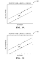
- Fig. 3A is a graph 300 of the relative phase of each of the phase centers that form the virtual receive antenna 112 where, given a single target in a range-Doppler bin, the relative phase of each vertical array of the virtual receive antenna 112 is illustrated.
- the slope of the linear phase progression is related to target azimuth.
- the phase offset ⁇ can be corrected prior to digital beam-forming in azimuth in order to eliminate grating lobes altogether.
- Fig. 3B is a graph 400 of the relative phase of each of the phase centers that form the virtual receive antenna 412 ( Fig. 4B ) where, given a single target in a range-Doppler bin, the relative phase of each vertical array of the virtual receive antenna 412 is illustrated.
- the slope of the linear phase progression is related to target azimuth.
- the phase offset can be corrected prior to digital beam-forming in azimuth in order to eliminate grating lobes altogether.
- the signal received from each antenna may be characterized by a complex number indicative of amplitude and phase.
- the phase offset delta phi ( ⁇ ) is computed, see Fig 3B .
- a target elevation is calculated by solving the equation above. Then, this phase offset is subtracted from the complex valued signals from half the elements of the virtual array, for example, from every other antenna for Fig 4B so that the corresponding phases in the Fig 3B are shifted so the phases of all the phase centers lie along the same line. Then, digital beam-forming will form a peak at the target azimuth angle without any grating lobes.
- Another technique to estimate target elevation angle is to perform digital beam-forming in azimuth with phase offset corrections for different target elevation angles.
- the phase offset that minimizes the grating lobe level determines the elevation angle of the target.
- the second technique can work for multiple targets in the same range-Doppler bin at different azimuth and elevation angles.
- Figs. 4A and 4B illustrate another non-limiting example of a MIMO antenna 410 antenna that establishes the virtual receive antenna 412 illustrated.
- the first transmit antenna 422 is formed of a single vertical array
- the second transmit antenna 424 is formed of a single vertical array.
- the transmit antennas are comparable to those shown in Fig. 1A .
- the receive antenna 420 is formed of one or more paired vertical arrays. Paired vertical arrays are advantageous with respect to the single element arrays shown in Fig. 1A because the paired vertical arrays have greater antenna gain.
- phase centers 446 of the receive antenna 420 are spaced apart by one wavelength ( ⁇ ) instead of the preferred one-half wavelength ( ⁇ /2) as is the case for the MIMO antenna 110 shown in Fig. 1 .
- the first group of phase-centers 456 and the second group of phase centers 458 of the virtual receive antenna 412 are arranged as indicated.
- the transmit antennas have a horizontal offset distance 428 of one-half wavelength ( ⁇ /2)
- the phase center pattern 412 is fully interleaved with all of the virtual receive antenna arrays having a horizontally spacing of one-half wavelength ( ⁇ /2).
- the vertical offset distance 426 of the transmit antennas involves tradeoffs in elevation measurement accuracy and ambiguities as previously discussed. To avoid ambiguity in estimating target elevation angle, the vertical offset distance can be selected to be one-half wavelength ( ⁇ /2).
- the MIMO antennas described thus far have been configured to provide elevation angle detection by vertically offsetting the transmit antennas. However, if there is no desire for elevation angle detection, the features that provide for improved grating lobe characteristics can still be utilized when the vertical offset distance is set to zero.
- Figs. 5A and 5B illustrate another non-limiting example of a MIMO antenna 510 antenna that establishes the virtual receive antenna 512 illustrated.
- the MIMO antenna 510 includes a first transmit antenna 522 configured to emit a first radar signal (not shown) toward a target (not shown).
- the first transmit antenna in this example is formed of a first vertical array of radiator elements that is a single string or single vertical array of radiator elements.
- the MIMO antenna also includes a second transmit antenna 524 configured to emit a second radar signal (not shown) toward the target.
- the second transmit antenna is formed of a second vertical array of radiator elements that is a single string and is distinct from the first vertical array.
- the MIMO antenna 510 also includes a receive antenna 520 configured to detect radar signals reflected by a target toward the receive antenna 520.
- the receive antenna 520 is formed of a plurality of paired vertical arrays of detector elements similar to the receive antenna 220 of Fig. 2A . Paired vertical arrays are advantageous with respect to the single element arrays shown in Fig. 1A because the paired vertical arrays have greater antenna gain.
- the phase centers 446 of the receive antenna 520 are spaced apart by one wavelength ( ⁇ ) instead of the preferred one-half wavelength ( ⁇ /2) as is the case for the MIMO antenna 110 shown in Fig. 1 .
- the first group of phase-centers 556 and the second group of phase centers 558 of the virtual receive antenna 512 are arranged as indicated.
- the transmit antennas have a horizontal offset distance 528 of one-half wavelength ( ⁇ /2)
- the phase center pattern 512 is fully interleaved with all of the virtual receive antenna arrays having a horizontally spacing of one-half wavelength ( ⁇ /2).
- Figs. 6A and 6B illustrate another non-limiting example of a MIMO antenna 610 antenna that establishes the virtual receive antenna 612 illustrated.
- the first transmit antenna 622 is formed of a first paired vertical array of radiator elements
- the second transmit antenna 624 is formed of a second paired vertical array of radiator elements.
- Having the transmit antenna be formed of paired vertical arrays is advantageous as the radar signals emitted by the transmit signal are more focused along the bore site of the antenna.
- horizontal offset distance 628 is increased relative to the prior example, so the transmit antennas are spaced apart by more than one-half wavelength ( ⁇ /2). As such, some of the interleaving of the virtual receive antenna 612 is lost when compared to Fig. 5B .
- the first transmit antenna 622 and the receive antenna 620 cooperate to establish a first group of phase-centers 658.
- the second transmit antenna 624 and the receive antenna 620 cooperate to establish a second group of phase-centers 658 distinct from the first group of phase-centers 656.
- the first group of phase-centers 656 are horizontally offset from the second group of phase-centers 658.
- the horizontal offset distance 628 may be advantageously selected so the first group of phase-centers 656 intersects a vertical line 660 that intersects the second group of phase-centers 658.
- the horizontal offset distance 628 may be advantageously selected so the first group of phase-centers 656 horizontally overlaps the second group of phase-centers 658.
- the horizontal offset distance 628 may also be advantageously selected so the first group of phase-centers 656 is interleaved with the second group of phase-centers 658 as opposed to having a phase center of one group coincide with a phase center from the other group.
- the radar signals emitted by the transmit antenna may be characterized by a wavelength.
- each of the plurality of paired vertical arrays that form the receive antenna 620 is horizontally spaced apart by one wavelength, and the horizontal offset distance 628 is selected so at least some of the phase-centers of the virtual receive antenna 612 are horizontally spaced apart by one-half wavelength.
- Some configurations provide for detecting an elevation angle to a target by vertically offsetting a pair of transmit antennas relative to each other. Some configurations provide for improved grating lobe characteristics when relatively wide antenna (i.e. paired vertical arrays) are used to improve gain by arranging the transmit antenna so a virtual receive antenna is established that provides for preferred grating lobe characteristic normally found with narrow antenna (i.e. single string arrays) that can be physically spaced apart by one-half wavelength.
- narrow antenna i.e. single string arrays
Landscapes
- Engineering & Computer Science (AREA)
- Radar, Positioning & Navigation (AREA)
- Remote Sensing (AREA)
- Physics & Mathematics (AREA)
- Computer Networks & Wireless Communication (AREA)
- General Physics & Mathematics (AREA)
- Electromagnetism (AREA)
- Variable-Direction Aerials And Aerial Arrays (AREA)
- Radar Systems Or Details Thereof (AREA)
Applications Claiming Priority (1)
| Application Number | Priority Date | Filing Date | Title |
|---|---|---|---|
| US14/197,404 US9568600B2 (en) | 2014-03-05 | 2014-03-05 | MIMO antenna with elevation detection |
Publications (1)
| Publication Number | Publication Date |
|---|---|
| EP2916144A1 true EP2916144A1 (fr) | 2015-09-09 |
Family
ID=52544410
Family Applications (1)
| Application Number | Title | Priority Date | Filing Date |
|---|---|---|---|
| EP15156400.2A Withdrawn EP2916144A1 (fr) | 2014-03-05 | 2015-02-24 | Antenne mimo avec détection d'élévation |
Country Status (3)
| Country | Link |
|---|---|
| US (1) | US9568600B2 (fr) |
| EP (1) | EP2916144A1 (fr) |
| CN (1) | CN104901021B (fr) |
Cited By (3)
| Publication number | Priority date | Publication date | Assignee | Title |
|---|---|---|---|---|
| WO2020158009A1 (fr) * | 2019-01-31 | 2020-08-06 | 三菱電機株式会社 | Dispositif d'antenne et dispositif radar |
| CN113811786A (zh) * | 2019-05-17 | 2021-12-17 | 三菱电机株式会社 | 天线装置及雷达装置 |
| EP3998494A4 (fr) * | 2019-07-22 | 2022-08-03 | Huawei Technologies Co., Ltd. | Système radar et véhicule |
Families Citing this family (70)
| Publication number | Priority date | Publication date | Assignee | Title |
|---|---|---|---|---|
| DE102014014864A1 (de) * | 2014-10-06 | 2016-04-07 | Astyx Gmbh | Abbildender Radarsensor mit horizontaler digitaler Strahlformung und vertikaler Objektvermessung durch Phasenvergleich bei zueinander versetzten Sendern |
| US10439283B2 (en) * | 2014-12-12 | 2019-10-08 | Huawei Technologies Co., Ltd. | High coverage antenna array and method using grating lobe layers |
| JP6396244B2 (ja) | 2015-03-25 | 2018-09-26 | パナソニック株式会社 | レーダ装置 |
| US9666937B2 (en) * | 2015-06-29 | 2017-05-30 | Waymo Llc | LTE MIMO antenna system for automotive carbon fiber rooftops |
| CN106546983B (zh) * | 2015-09-17 | 2021-11-12 | 松下电器产业株式会社 | 雷达装置 |
| EP3156817B8 (fr) * | 2015-10-12 | 2019-01-09 | Aptiv Technologies Limited | Antenne de radar mimo de détection d'angle d'élévation |
| US10871555B1 (en) | 2015-12-02 | 2020-12-22 | Apple Inc. | Ultrasonic sensor |
| CN105406181A (zh) * | 2015-12-04 | 2016-03-16 | 福建星网锐捷网络有限公司 | 单极天线及多输入多输出天线 |
| CN105449351B (zh) * | 2015-12-07 | 2018-04-17 | 南京邮电大学 | 一种双极化大规模mimo贴片阵列天线 |
| US10446938B1 (en) | 2015-12-23 | 2019-10-15 | Apple Inc. | Radar system including dual receive array |
| DE102016203160A1 (de) * | 2016-02-29 | 2017-08-31 | Robert Bosch Gmbh | Radarsystem, umfassend eine Antennenanordnung zum Senden und Empfangen elektromagnetischer Strahlung |
| US9846228B2 (en) | 2016-04-07 | 2017-12-19 | Uhnder, Inc. | Software defined automotive radar systems |
| US9689967B1 (en) | 2016-04-07 | 2017-06-27 | Uhnder, Inc. | Adaptive transmission and interference cancellation for MIMO radar |
| US10261179B2 (en) | 2016-04-07 | 2019-04-16 | Uhnder, Inc. | Software defined automotive radar |
| US9806914B1 (en) | 2016-04-25 | 2017-10-31 | Uhnder, Inc. | Successive signal interference mitigation |
| US10573959B2 (en) | 2016-04-25 | 2020-02-25 | Uhnder, Inc. | Vehicle radar system using shaped antenna patterns |
| US9791551B1 (en) | 2016-04-25 | 2017-10-17 | Uhnder, Inc. | Vehicular radar system with self-interference cancellation |
| WO2017187242A1 (fr) | 2016-04-25 | 2017-11-02 | Uhnder, Inc. | Micro-doppler à balayage multiple à la demande pour véhicule |
| US9575160B1 (en) | 2016-04-25 | 2017-02-21 | Uhnder, Inc. | Vehicular radar sensing system utilizing high rate true random number generator |
| WO2017187306A1 (fr) | 2016-04-25 | 2017-11-02 | Uhnder, Inc. | Filtrage adaptatif pour atténuation d'interférence fmcw dans des systèmes de radar pmcw |
| EP3449275A4 (fr) | 2016-04-25 | 2020-01-01 | Uhnder, Inc. | Atténuation d'interférences entre ondes entretenues à modulation de phase |
| US9954955B2 (en) | 2016-04-25 | 2018-04-24 | Uhnder, Inc. | Vehicle radar system with a shared radar and communication system |
| WO2017187304A2 (fr) | 2016-04-25 | 2017-11-02 | Uhnder, Inc. | Radar numérique à ondes continues modulées en fréquence mettant en œuvre une modulation constante de l'enveloppe personnalisée |
| US11199618B2 (en) | 2016-06-17 | 2021-12-14 | Apple Inc. | Radar antenna array |
| US9753121B1 (en) | 2016-06-20 | 2017-09-05 | Uhnder, Inc. | Power control for improved near-far performance of radar systems |
| WO2018051288A1 (fr) | 2016-09-16 | 2018-03-22 | Uhnder, Inc. | Configuration de radar virtuel pour réseau 2d |
| US10236965B1 (en) | 2016-10-04 | 2019-03-19 | Sprint Spectrum L.P. | Dynamic multi-antenna communication |
| KR102653129B1 (ko) * | 2016-11-28 | 2024-04-02 | 주식회사 에이치엘클레무브 | 레이더 장치 및 그를 위한 안테나 장치 |
| KR102647693B1 (ko) * | 2016-11-28 | 2024-03-15 | 주식회사 에이치엘클레무브 | 레이더 장치 및 그의 오차 보정 방법 |
| KR102662232B1 (ko) * | 2016-11-28 | 2024-05-02 | 주식회사 에이치엘클레무브 | 다중입력 다중출력 안테나부를 포함하는 레이더 장치 |
| KR102662238B1 (ko) * | 2016-11-28 | 2024-05-02 | 주식회사 에이치엘클레무브 | 레이더 장치 및 그를 위한 안테나 장치 |
| DE102016224900A1 (de) * | 2016-12-14 | 2018-06-14 | Robert Bosch Gmbh | MIMO-Radarsensor für Kraftfahrzeuge |
| WO2018146634A1 (fr) | 2017-02-10 | 2018-08-16 | Uhnder, Inc. | Augmentation de la performance d'un pipeline de réception d'un radar avec optimisation de mémoire |
| US10908272B2 (en) | 2017-02-10 | 2021-02-02 | Uhnder, Inc. | Reduced complexity FFT-based correlation for automotive radar |
| US11454697B2 (en) | 2017-02-10 | 2022-09-27 | Uhnder, Inc. | Increasing performance of a receive pipeline of a radar with memory optimization |
| CN108471324A (zh) * | 2017-02-23 | 2018-08-31 | 索尼公司 | 电子设备、通信装置和信号处理方法 |
| US10677918B2 (en) | 2017-02-28 | 2020-06-09 | Analog Devices, Inc. | Systems and methods for improved angular resolution in multiple-input multiple-output (MIMO) radar |
| WO2018196001A1 (fr) * | 2017-04-28 | 2018-11-01 | SZ DJI Technology Co., Ltd. | Ensemble de détection pour conduite autonome |
| EP3413077B1 (fr) * | 2017-06-09 | 2020-02-19 | Veoneer Sweden AB | Détection d'objet vertical améliorée pour un système de radar de véhicule |
| JP2019015554A (ja) * | 2017-07-05 | 2019-01-31 | 日本無線株式会社 | レーダ装置およびレーダ装置の演算方法 |
| JP7023563B2 (ja) * | 2017-10-05 | 2022-02-22 | 日本無線株式会社 | Mimoレーダー用アンテナ構造 |
| JP6887091B2 (ja) * | 2017-10-10 | 2021-06-16 | パナソニックIpマネジメント株式会社 | レーダ装置 |
| US11105890B2 (en) | 2017-12-14 | 2021-08-31 | Uhnder, Inc. | Frequency modulated signal cancellation in variable power mode for radar applications |
| DE102018200751A1 (de) * | 2018-01-18 | 2019-07-18 | Robert Bosch Gmbh | Radarvorrichtung und Verfahren zum Betreiben einer Radarvorrichtung |
| US11187795B2 (en) * | 2018-03-19 | 2021-11-30 | Panasonic Intellectual Property Management Co., Ltd. | Radar device |
| KR102167097B1 (ko) | 2018-04-09 | 2020-10-16 | 주식회사 만도 | 레이더 장치 및 그를 위한 안테나 장치 |
| KR102167084B1 (ko) * | 2018-04-09 | 2020-10-16 | 주식회사 만도 | 레이더 장치 및 그를 위한 안테나 장치 |
| JP7061534B2 (ja) * | 2018-08-02 | 2022-04-28 | 日立Astemo株式会社 | レーダ装置 |
| IL261636A (en) * | 2018-09-05 | 2018-10-31 | Arbe Robotics Ltd | Deflected MIMO antenna array for vehicle imaging radars |
| CN109085541B (zh) * | 2018-09-07 | 2021-02-02 | 杭州捍鹰科技有限公司 | Mimo雷达阵列天线及其信号处理方法 |
| US10386462B1 (en) * | 2018-10-02 | 2019-08-20 | Oculii Corp. | Systems and methods for stereo radar tracking |
| DE102018124503A1 (de) * | 2018-10-04 | 2020-04-09 | HELLA GmbH & Co. KGaA | Radarsystem für ein Fahrzeug |
| US11474225B2 (en) | 2018-11-09 | 2022-10-18 | Uhnder, Inc. | Pulse digital mimo radar system |
| US11340329B2 (en) * | 2018-12-07 | 2022-05-24 | Apple Inc. | Electronic devices with broadband ranging capabilities |
| KR20200097101A (ko) * | 2019-02-07 | 2020-08-18 | 현대모비스 주식회사 | 차량용 레이더 장치 및 그 제어 방법 |
| US11681017B2 (en) | 2019-03-12 | 2023-06-20 | Uhnder, Inc. | Method and apparatus for mitigation of low frequency noise in radar systems |
| US11262434B2 (en) * | 2019-04-01 | 2022-03-01 | GM Global Technology Operations LLC | Antenna array design and processing to eliminate false detections in a radar system |
| US11047971B2 (en) * | 2019-05-20 | 2021-06-29 | GM Global Technology Operations LLC | Radar system and control method for use in a moving vehicle |
| US11181614B2 (en) * | 2019-06-06 | 2021-11-23 | GM Global Technology Operations LLC | Antenna array tilt and processing to eliminate false detections in a radar system |
| KR102279302B1 (ko) * | 2019-11-07 | 2021-07-20 | 현대모비스 주식회사 | 차량용 레이더 장치 및 그 제어 방법 |
| JP2021085748A (ja) * | 2019-11-27 | 2021-06-03 | ソニーセミコンダクタソリューションズ株式会社 | レーダー装置、レーダー装置の製造方法及び送受信機 |
| US12078748B2 (en) | 2020-01-13 | 2024-09-03 | Uhnder, Inc. | Method and system for intefrence management for digital radars |
| CN111693978B (zh) * | 2020-05-13 | 2023-04-07 | 复旦大学 | 基于mimo毫米波雷达的散点检测方法 |
| US11762060B2 (en) | 2020-08-27 | 2023-09-19 | Aptiv Technologies Limited | Height-estimation of objects using radar |
| US11762079B2 (en) * | 2020-09-30 | 2023-09-19 | Aurora Operations, Inc. | Distributed radar antenna array aperture |
| WO2022139844A1 (fr) * | 2020-12-24 | 2022-06-30 | Intel Corporation | Procédé, système et appareil radar |
| KR102288673B1 (ko) * | 2020-12-28 | 2021-08-12 | 주식회사 비트센싱 | 수평 간격 및 수직 간격으로 배치되는 복수의 안테나를 포함하는 레이더 장치 |
| CN113777574B (zh) * | 2021-08-30 | 2024-09-10 | 深圳市塞防科技有限公司 | 稀疏阵列解栅瓣方法、装置及相关设备 |
| CN114267954A (zh) * | 2021-12-20 | 2022-04-01 | 中国电子科技集团公司第十四研究所 | 一种基于虚拟阵元的大规模串馈微带阵列天线 |
| US20230314557A1 (en) * | 2022-04-05 | 2023-10-05 | Honeywell International Inc. | High isolation between transmit and receive antenna in fmcw radars |
Citations (4)
| Publication number | Priority date | Publication date | Assignee | Title |
|---|---|---|---|---|
| EP0947852A1 (fr) * | 1998-04-02 | 1999-10-06 | Toyota Jidosha Kabushiki Kaisha | Appareil radar |
| WO2010095946A1 (fr) * | 2009-02-20 | 2010-08-26 | Nederlandse Organisatie Voor Toegepast-Natuurwetenschappelijk Onderzoek Tno | Procédé de détection d'un diffuseur dans une structure, système radar et progiciel informatique |
| US20110140952A1 (en) * | 2009-09-15 | 2011-06-16 | Thales | Airborne radar having a wide angular coverage, notably for the sense-and-avoid function |
| KR20130115510A (ko) * | 2012-04-12 | 2013-10-22 | 삼성탈레스 주식회사 | Mimo 신호처리 기법을 이용한 다중빔 방식의 후측방 레이더 |
Family Cites Families (14)
| Publication number | Priority date | Publication date | Assignee | Title |
|---|---|---|---|---|
| DE102008038365A1 (de) * | 2008-07-02 | 2010-01-07 | Adc Automotive Distance Control Systems Gmbh | Fahrzeug-Radarsystem und Verfahren zur Bestimmung einer Position zumindest eines Objekts relativ zu einem Fahrzeug |
| JP4766405B2 (ja) * | 2008-11-14 | 2011-09-07 | トヨタ自動車株式会社 | レーダ装置 |
| EP2391906B1 (fr) * | 2009-01-30 | 2016-12-07 | Teledyne Australia Pty Ltd. | Appareil et procédé pour aider les véhicules à décollage à la verticale |
| US7986260B2 (en) * | 2009-02-18 | 2011-07-26 | Battelle Memorial Institute | Circularly polarized antennas for active holographic imaging through barriers |
| US8289203B2 (en) * | 2009-06-26 | 2012-10-16 | Src, Inc. | Radar architecture |
| DE102009029291A1 (de) * | 2009-09-09 | 2011-03-10 | Robert Bosch Gmbh | Planare Antenneneinrichtung für eine Radarsensorvorrichtung |
| US8466829B1 (en) * | 2009-09-14 | 2013-06-18 | Lockheed Martin Corporation | Super-angular and range-resolution with phased array antenna and multifrequency dither |
| FR2950147B1 (fr) * | 2009-09-15 | 2012-07-13 | Thales Sa | Radar a agilite de faisceau, notamment pour la fonction de detection et d'evitement d'obstacles |
| KR101137088B1 (ko) * | 2010-01-06 | 2012-04-19 | 주식회사 만도 | 통합 레이더 장치 및 통합 안테나 장치 |
| US8797208B2 (en) * | 2010-12-13 | 2014-08-05 | Sony Corporation | Active radar system and method |
| DE102010064348A1 (de) * | 2010-12-29 | 2012-07-05 | Robert Bosch Gmbh | Radarsensor für Kraftfahrzeuge |
| US9121943B2 (en) * | 2011-05-23 | 2015-09-01 | Sony Corporation | Beam forming device and method |
| US9203160B2 (en) * | 2011-12-21 | 2015-12-01 | Sony Corporation | Antenna arrangement and beam forming device |
| CN103728606A (zh) * | 2014-01-16 | 2014-04-16 | 西安电子科技大学 | 机载mimo雷达的多普勒通道关联两级降维方法 |
-
2014
- 2014-03-05 US US14/197,404 patent/US9568600B2/en active Active
- 2014-12-31 CN CN201410858408.2A patent/CN104901021B/zh active Active
-
2015
- 2015-02-24 EP EP15156400.2A patent/EP2916144A1/fr not_active Withdrawn
Patent Citations (4)
| Publication number | Priority date | Publication date | Assignee | Title |
|---|---|---|---|---|
| EP0947852A1 (fr) * | 1998-04-02 | 1999-10-06 | Toyota Jidosha Kabushiki Kaisha | Appareil radar |
| WO2010095946A1 (fr) * | 2009-02-20 | 2010-08-26 | Nederlandse Organisatie Voor Toegepast-Natuurwetenschappelijk Onderzoek Tno | Procédé de détection d'un diffuseur dans une structure, système radar et progiciel informatique |
| US20110140952A1 (en) * | 2009-09-15 | 2011-06-16 | Thales | Airborne radar having a wide angular coverage, notably for the sense-and-avoid function |
| KR20130115510A (ko) * | 2012-04-12 | 2013-10-22 | 삼성탈레스 주식회사 | Mimo 신호처리 기법을 이용한 다중빔 방식의 후측방 레이더 |
Cited By (5)
| Publication number | Priority date | Publication date | Assignee | Title |
|---|---|---|---|---|
| WO2020158009A1 (fr) * | 2019-01-31 | 2020-08-06 | 三菱電機株式会社 | Dispositif d'antenne et dispositif radar |
| JPWO2020158009A1 (ja) * | 2019-01-31 | 2021-09-30 | 三菱電機株式会社 | アンテナ装置及びレーダ装置 |
| CN113811786A (zh) * | 2019-05-17 | 2021-12-17 | 三菱电机株式会社 | 天线装置及雷达装置 |
| EP3961241A4 (fr) * | 2019-05-17 | 2022-05-04 | Mitsubishi Electric Corporation | Dispositif d'antenne et dispositif radar |
| EP3998494A4 (fr) * | 2019-07-22 | 2022-08-03 | Huawei Technologies Co., Ltd. | Système radar et véhicule |
Also Published As
| Publication number | Publication date |
|---|---|
| CN104901021A (zh) | 2015-09-09 |
| US20150253420A1 (en) | 2015-09-10 |
| US9568600B2 (en) | 2017-02-14 |
| CN104901021B (zh) | 2019-07-02 |
Similar Documents
| Publication | Publication Date | Title |
|---|---|---|
| US9568600B2 (en) | MIMO antenna with elevation detection | |
| EP2916140A2 (fr) | Antenne mimo présentant des meilleures caractéristiques des lobes secondaires | |
| US9541639B2 (en) | MIMO antenna with elevation detection | |
| EP3156817B1 (fr) | Antenne de radar mimo de détection d'angle d'élévation | |
| EP3001221B1 (fr) | Système radar et procédé pour des signaux d'antenne virtuelle | |
| US20130088393A1 (en) | Transmit and receive phased array for automotive radar improvement | |
| US11079485B2 (en) | Antenna device | |
| US9285462B2 (en) | Antenna apparatus | |
| US11041938B2 (en) | Radar apparatus | |
| CN112136060B (zh) | 用于机动车的mimo雷达传感器 | |
| US20210263139A1 (en) | Distributed Monopulse Radar Antenna Array for Collision Avoidance | |
| US11843162B2 (en) | MIMO radar system for an aerial vehicle | |
| US20240039173A1 (en) | Multiple input multiple steered output (mimso) radar | |
| US10637130B2 (en) | Antenna device | |
| US20220146657A1 (en) | Multiple-input multiple-output imaging radar system | |
| Shabalin et al. | Millimeter-wave phased antenna array for automotive radar | |
| US20200358207A1 (en) | Antenna array for a radar sensor | |
| CN112639525A (zh) | 角度分辨的雷达传感器 | |
| US20240219552A1 (en) | Mimo radar using a frequency scanning antenna | |
| Nikishov et al. | mmWave Antenna Array Unit for Imaging Radar | |
| CN116794603A (zh) | 一种毫米波雷达天线阵列及毫米波雷达 | |
| JP2018204974A (ja) | レーダ装置 | |
| CN114512786A (zh) | 改善角度分辨率的天线布置方法、雷达 | |
| Debing | Two-beam technique to track a target in low elevation angles for phased array radar |
Legal Events
| Date | Code | Title | Description |
|---|---|---|---|
| PUAI | Public reference made under article 153(3) epc to a published international application that has entered the european phase |
Free format text: ORIGINAL CODE: 0009012 |
|
| AK | Designated contracting states |
Kind code of ref document: A1 Designated state(s): AL AT BE BG CH CY CZ DE DK EE ES FI FR GB GR HR HU IE IS IT LI LT LU LV MC MK MT NL NO PL PT RO RS SE SI SK SM TR |
|
| AX | Request for extension of the european patent |
Extension state: BA ME |
|
| STAA | Information on the status of an ep patent application or granted ep patent |
Free format text: STATUS: THE APPLICATION IS DEEMED TO BE WITHDRAWN |
|
| 18D | Application deemed to be withdrawn |
Effective date: 20160310 |