EP2916070A2 - Einstellbare Wirbelflammenvorrichtung - Google Patents
Einstellbare Wirbelflammenvorrichtung Download PDFInfo
- Publication number
- EP2916070A2 EP2916070A2 EP14181342.8A EP14181342A EP2916070A2 EP 2916070 A2 EP2916070 A2 EP 2916070A2 EP 14181342 A EP14181342 A EP 14181342A EP 2916070 A2 EP2916070 A2 EP 2916070A2
- Authority
- EP
- European Patent Office
- Prior art keywords
- control head
- vortex flame
- flame device
- adjustable vortex
- flow
- Prior art date
- Legal status (The legal status is an assumption and is not a legal conclusion. Google has not performed a legal analysis and makes no representation as to the accuracy of the status listed.)
- Granted
Links
- 230000007246 mechanism Effects 0.000 claims abstract description 26
- 239000000446 fuel Substances 0.000 claims description 8
- 238000004891 communication Methods 0.000 claims description 4
- 239000012530 fluid Substances 0.000 claims description 2
- 238000002485 combustion reaction Methods 0.000 description 8
- 230000000694 effects Effects 0.000 description 4
- 238000001816 cooling Methods 0.000 description 2
- 230000002093 peripheral effect Effects 0.000 description 2
- 238000007789 sealing Methods 0.000 description 1
Images


Classifications
-
- F—MECHANICAL ENGINEERING; LIGHTING; HEATING; WEAPONS; BLASTING
- F23—COMBUSTION APPARATUS; COMBUSTION PROCESSES
- F23C—METHODS OR APPARATUS FOR COMBUSTION USING FLUID FUEL OR SOLID FUEL SUSPENDED IN A CARRIER GAS OR AIR
- F23C7/00—Combustion apparatus characterised by arrangements for air supply
- F23C7/002—Combustion apparatus characterised by arrangements for air supply the air being submitted to a rotary or spinning motion
- F23C7/004—Combustion apparatus characterised by arrangements for air supply the air being submitted to a rotary or spinning motion using vanes
-
- F—MECHANICAL ENGINEERING; LIGHTING; HEATING; WEAPONS; BLASTING
- F23—COMBUSTION APPARATUS; COMBUSTION PROCESSES
- F23D—BURNERS
- F23D14/00—Burners for combustion of a gas, e.g. of a gas stored under pressure as a liquid
- F23D14/28—Burners for combustion of a gas, e.g. of a gas stored under pressure as a liquid in association with a gaseous fuel source, e.g. acetylene generator, or a container for liquefied gas
-
- F—MECHANICAL ENGINEERING; LIGHTING; HEATING; WEAPONS; BLASTING
- F23—COMBUSTION APPARATUS; COMBUSTION PROCESSES
- F23D—BURNERS
- F23D2206/00—Burners for specific applications
- F23D2206/0094—Gas burners adapted for use in illumination and heating
Definitions
- the present invention relates to a vortex flame device and, particularly to an adjustable vortex flame device.
- U.S. Patent No. 7,097,448 shows a vortex type gas lamp for producing an upwardly directed vortex flame inside a surrounding and confined boundary of rotating body of air.
- An interface is located between the body of air which is devoid of gas and a central region of gas which is bounded by the interface during the operation of the gas lamp. All of the combustion of gas substantially occurs inside the interface.
- the gas lamp has a central axis and includes a base supplying combustible gas without air at and nearly adjacent to the central axis.
- a shield includes first and second axially extending sections structurally attached to the base in a fluid sealing relationship.
- the first and second sections of the shield are substantially identical and transparent to light and each includes an impermeable wall having an arcuate inner surface and an arcuate outer surface. Each of the first and second sections of the shield has first and second edges extended axially.
- the gas lamp further includes first and second walls alternately overlapping one another. The first and second walls are adjacent to their edges and are spaced from one another so as to form tangentially directed ports, thereby forming an axially extending mixing chamber open at its side only through the ports.
- the first and second sections are arranged that at the base they surround the entry of combustible gas and which receives air for combustion only through the ports, whereby a flame results from the combustion process is spaced from the inner surfaces, and the peripheral body of air is devoid of gas entering through the ports.
- a flame will extinguish.
- height and swirling pattern of the flame are greatly disturbed by excess airflow through the ports due to wind, if the device is placed under an environment with wind. Notwithstanding, the base of the chamber is also heated during combustion and if there is no enough airflow through the base to provide cooling, the top surface of the base can be very hot and not safe to touch.
- U.S. Design Patent No. 621,873 shows a fire tornado lamp.
- a base includes a plurality of ports disposed circumferentially.
- a shield is transparent to light and hollow and includes a passage. The base and the shield are connected to each other.
- Each port extends radially with respect to and is in communication with the passage.
- Each port is configured that it induces air into the passage in a direction substantially tangential to a circumference of the passage.
- the guided air flow that provides for combustion and cooling can only enters the chamber through the ports above the bottom of burning flame at an angle perpendicular to the flame direction. This configuration can generate a swift swirling flame and induce strong convection during combustion, but it is difficult to control the swirling speed and pattern of the flame and the base of the device can be very hot.
- a user can't interact with either of the two set forth devices to adjust the size of vortex flames of the devices.
- the present invention is, therefore, intended to obviate or at least alleviate the problems encountered in the prior art.
- an adjustable vortex flame device includes a control head delimiting a through hole with an opening.
- the control head includes a flow guiding mechanism including a plurality of vanes disposed around a circumference of the opening one after another, and two adjacent vanes includes a spiral air passage formed therebetween.
- a flow control head inserts in the through hole.
- the flow control head includes a first member and a second member detachably engaging with the first member.
- the flow control head delimits a first chamber and a second chamber connecting to the first chamber. Two channels extend in the first member and to an outer periphery of the flow control head. The two channels connect to the first chamber.
- the flow control head has two flow outlets defined at distal ends of the two channels and a flow inlet defined at a distal end of the second chamber.
- the adjustable vortex flame device in use includes a fuel reservoir fluidly connecting to the flow inlet of the flow control head.
- the first chamber extends longitudinally along a first axis.
- the two channels are disposed symmetrically with respect to the first axis.
- Each of the two channels extends longitudinally along a second axis.
- the second axis offsets radially from the first axis.
- a hollow and transparent shield is disposed above the control head and delimits a space fluidly connecting to the through hole.
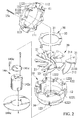
- Figs. 1 through 6 show an adjustable vortex flame device in accordance with a first embodiment of the present invention.
- the adjustable vortex flame device includes a control head 10.
- the control head 10 delimits a through hole with an opening 13 with a diametrical size.
- the control head 10 includes a base having an inner periphery thereof delimiting the opening 13.
- the flow guiding and control mechanisms 20 and 30 are mounted on the base.
- the base includes a first base member 11 and a second base member 12 joined to the first base member 11.
- the opening 13 defines a first orifice 111 extending through the first base member 11 and a second orifice 121 extending through the second base member 12, respectively.
- the first base member 11 has a first engaging end 112 and the second base member 12 has a second engaging end 122 engaging with the first engaging end 112.
- the first engaging end 112 forms a plurality of first ridges each include first and second edges 1121 and 1122 and an apex defined therebetween and the second engaging end 122 forms a plurality of second ridges each include third and fourth edges 1221 and 1222 and an apex defined therebetween respectively, and the first and second edges 1121 and 1122 of one of the plurality of first ridges correspondingly face the third and fourth edges 1221 and 1222 of one of the plurality of second ridges.
- the first and second edges 1121 and 1122 of one of the plurality of first ridges have an included angle of greater than 90 degrees.
- the third and fourth edges 1121 and 1122 of one of the plurality of second ridges have an included angle of greater than 90 degrees.
- At least one fastener 15c is used to secure the first and second base members 11 and 12 together.
- the at least one fastener 15c includes outer threads and the first and second base members 11 and 12 each include at least one engaging hole having inner threads, and the at least one fastener 15c engages in and in thread engagement with the engaging holes of the first and second member 11 and 12.
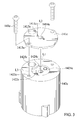
- a flow control head 14c inserts in the through hole delimited by the control head 10.
- the flow control head 14c includes a first member 141c and a second member 142c detachably engaging with the first member 141c.
- the first member 141c is disposed above the second member 142c in a vertical direction.
- the first and second members 141c and 142c are secured by a fastening means 143c.
- the fastening means 143c are bolts.
- Two bolts 143c are used to secure the first and second members 141c and 142c together.
- the first member 141c includes two first holes 1413c extending therethrough.
- the second member 142c includes two second holes 1423c extending therein.
- the first and second members 141c and 142c are secured together with the two bolts 143c respectively inserting through the two first holes 1413c and engaging in the two second holes 1423c.
- Each of the two bolts 143c has outer threads.
- a platform 144c bears the second member 142c of the flow control head 14c.
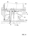
- the flow control head 14c delimits a first chamber 1421c and a second chamber 1422c connecting to the first chamber 1421c.
- Two channels 1411c extend in the first member 141c and to an outer periphery of the flow control head 14c and connect to the first chamber 1421c.
- the flow control head 14c has two flow outlets defined at distal ends of the two channels 1411c and a flow inlet defined at a distal end of the second chamber 1422c.
- the adjustable vortex flame device in use includes a fuel reservoir 60c fluidly connecting to the flow inlet of the flow control head 14c.
- the first chamber 1421c is disposed between and interconnects the two channels 1411c and the second chamber 1422c.
- the first chamber 1421c extends longitudinally along a first axis L1.
- the two channels 1411c are disposed symmetrically with respect to the first axis L1.
- Each of the two channels 1411c extends longitudinally along a second axis L2.
- the second axis L2 offsets radially from the first axis L1.
- Each of the flow outlets radially offsets from the first axis L1 at a first radial distance.
- the first member 1421c is substitutable with another first member 1421c which includes each of flow outlets radially offsetting from the first axis L1 at a second radial distance different from the first radial distance.
- the second chamber 1422c extends longitudinally along a third axis L3.
- the third axis L3 is parallel to the first axis L1.
- the third axis L3 is offset radi
- the control head 10 includes a flow guiding mechanism 20 including a plurality of vanes 21.
- the flow guiding mechanism 20 is disposed below the opening 13.
- the plurality of vanes 21 are disposed around a circumference of the opening 13 one after another, with two adjacent vanes 21 including a spiral air passage 22 formed therebetween.
- Each of the plurality of vanes 21 has a first extension 211 secured between the first edge 1121 of one of the plurality of first ridges and the third edge 1221 of one of the plurality of second ridges and a second extension 212 extending from the first extension 211, and the air passage 22 between two adjacent vanes 21 are delimited by the second extensions 212 thereof.
- Each of the plurality of vanes 21 includes the second extension 212 extending from the first extension 211 obliquely.
- the first and second extensions 211 and 212 have an included angle of greater than 90 degrees.
- the plurality of vanes 21 are held securely between the first and second base members 11 and 12 with a plurality of joints 1223 which insert through the first extensions 211 of the plurality of vanes 21 and fixed to the plurality of securing sections 1123.
- the plurality of securing sections 1123 are formed on the first base member 11 and the plurality of joints 1223 extend from the second base member 12, respectively.
- the plurality of securing sections 1123 define a plurality of apertures and the plurality of joints 1223 define a plurality of projections, respectively, but not limiting.
- the plurality of vanes 21 include a plurality of cavities 2111 the plurality of joints 1223 insert through. Therefore, the plurality of joints 1223 insert through the plurality of vanes 21.
- the control head 10 includes a control mechanism 30 delimiting a hole 31.
- the control mechanism 30 is an annular member secured to the first base member 11, and the hole 31 is delimited by an inner periphery of the annular member.
- the first base member 11 has at least one first fixing end 113 connecting with the opening 13, and the control mechanism 30 has at least one second fixing end 32 engaging with the at least one first fixing end 113.
- Fig. 2 shows the first base member 11 includes a plurality of first fixing ends 113 defining a plurality of slots and the control mechanism 30 includes a plurality of second fixing ends 32 defining a plurality of projections respectively.
- the plurality of first fixing ends 113 are spaced apart one another circumferentially along the inner periphery of the first base member 11.
- the plurality of second fixing ends are spaced apart one another circumferentially along the inner periphery of the control mechanism 30.
- the hole 31 has a diametrical size and which varies with respect to a size of a vortex flames of the adjustable vortex flame device.
- the hole 31 corresponds to and in communication with the opening 13.
- the hole 31 is in a smaller diametrical size than the opening 13.
- the hole 31 of the control mechanism 30 has a first diametrical size.
- the control mechanism 30 is substitutable with another control mechanism 30 which includes the hole 31 thereof having a second diametrical size different from the first diametrical size, thereby influencing a size of a vortex flame of the adjustable vortex flame device.
- a hollow and transparent shield 40 is disposed above the control head 10 and adjacent to the control mechanism 30.
- the shield 40 delimits a space 41 in communication with the hole 31 of the control mechanism 30.
- the space 41 fluidly connects to the through hole delimited by the control head 10.
- the shield 40 has two opposite open ends 42.
- the space 41 is between the two open ends 42.
- a seat 50 with at least one auxiliary air inlet 51 is fixed to and bears the base and with which a fuel reservoir 60 is adapted to connect.
- the base includes at least one connecting section 123 with which the seat 50 is engaged to mount securely on the seat 50.
- a heat detecting system A adapted to detect a temperature of a vortex flame of the adjustable vortex flame device inserts through the flow control head 14c.
- the first member 141c includes a third hole 1414c extending therethrough.
- the second member 142c includes a fourth hole 1424c extending therethrough.
- the heat detecting system A inserts through the flow control head 14c from the third and fourth hole 1414c and 1424c.
- the third and fourth holes 1414c and 1424c correspond to each other. Centers of the third and fourth holes 1414c and 1424c are disposed on the first axis L1.
- An ignition system B also extends through the flow control head 14c.
- the first member 141c includes a fifth hole 1415c extending therethrough.
- the second member 142c includes a sixth hole 1425c extending therethrough.
- the ignition system B extends through the flow control head 14c from the fifth and sixth holes 1415c and 1425c.
- the fifth and sixth holes 1415c and 1425c correspond to each other. Centers of the fifth and sixth holes 1415c and 1425c are disposed on the first axis L1.
- a pipe E can deliver fuel in the fuel reservoir 60c to the flow control head 14c.
- the pipe E has a first end fluidly engaging with the fuel reservoir 60c and a second end inserting in the second chamber 1422c. The second end of the pipe E protrudes into the first chamber 1421c.
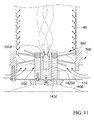
- FIGs. 7 through 12 show an adjustable vortex flame device in accordance with a second embodiment of the present invention.
- the second embodiment is similar to the first embodiment.
- a control head 10d includes a base having an inner periphery thereof delimiting an opening 13.
- a flow guiding and control mechanisms 20d and 30d are mounted on the base.
- the base includes a first base member 11d and a second base member 12d joined to the first base member 11d.
- the first base member 11d has a first engaging end and the second base member 12d has a second engaging end engaging with the first engaging end.
- the first engaging end forms a plurality of first ridges each include first and second edges and an apex defined therebetween and the second engaging end forms a plurality of second ridges each include third and fourth edges and an apex defined therebetween respectively.
- the first and second edges of one of the plurality of first ridges correspondingly face the third and fourth edges of one of the plurality of second ridges.
- the first and second edges of one of the plurality of first ridges have an included angle of greater than 90 degrees.
- the third and fourth edges of one of the plurality of second ridges have an included angle of greater than 90 degrees.
- At least one fastener 15d is used to secure first and second base members 11d and 12d together.
- the at least one fastener 15d includes outer threads and the first and second base members 11b and 12d each include at least one engaging hole having inner threads, and the at least one fastener 15d engages in and in thread engagement with the engaging holes of the first and second member 11d and 12d.
- a flow control head 14d inserts in a through hole delimited by a control head 10d.
- the flow control head 14d includes a first member 141d and a second member 142d detachably engaging with the first member 141d.
- the first member 141 d is disposed above the second member 142d in a vertical direction.
- the first and second members 141c and 142c are secured by a fastening means 143c.
- the fastening means 143d defines outer threads on the outer periphery of the first member 141 d and inner threads on the inner periphery of the second chamber 1422d.
- the first and second members 141d and 142d are secured together with the outer thread 143b engaging with the inner threads 143d.
- the first member 142d includes an outer periphery thereof including at least one ear 1416d protruding therefrom. It is effort saving and convenient that a user can grip and apply a force on the ear 1416d to join the first member 141d to the second member 142d.
- the flow control head 14d delimits a first chamber 1421d and a second chamber 1422d connecting to the first chamber 1421d.
- Two channels 1411d extend in the first member 141d and to an outer periphery of the flow control head 14d and connect to the first chamber 1421d.
- the flow control head 14d has two flow outlets defined at distal ends of the two channels 1411d and a flow inlet defined at a distal end of the second chamber 1422d.
- the adjustable vortex flame device in use includes a fuel reservoir 60d fluidly connecting to the flow inlet of the flow control head 14d.
- the first chamber 1421 d is disposed between and interconnects the two channels 1411d and the second chamber 1422d.
- the first chamber 1421d extends longitudinally along a first axis L1.
- the two channels 1411d are disposed symmetrically with respect to the first axis L1.
- Each of the two channels 1411d extends longitudinally along a second axis L2.
- the second axis L2 offsets radially from the first axis L1.
- Each of the flow outlets radially offsets from the first axis L1 at a first radial distance.
- the first member 1421d is substitutable with another first member 1421d which includes each of flow outlets radially offsetting from the first axis L1 at a second radial distance different from the first radial distance.
- the second chamber 1422d extends longitudinally along a third axis L3.
- the third axis L3 is parallel to the first axis L1.
- the third axis L3 is offset radially from the first axis L1.
- Each of the two channels 1411d extending obliquely from the first chamber 1421d to the outer periphery of the flow control head 14d.
- the two channels 1411d extend divergently from each other from the first chamber 1421d to the outer periphery of the flow control head 14d.
- the second axis L2 tilts from the first axis L1 at a first angle ⁇ .
- the first angle ⁇ is less than 90 degrees.
- the first angle ⁇ is 17.5 degrees.
- Each of the plurality of vanes 21d has a first extension secured between the first edge of one of the plurality of first ridges and the third edge of one of the plurality of second ridges and a second extension 212d extending from the first extension 211d.
- An air passage 22d between the two adjacent vanes 21d are delimited by the second extensions 212d thereof.
- Each of the plurality of vanes 21d includes the second extension 212d thereof extending from the first extension 211d.
- the second extension 212d defines a surface and a tangent plane of the surface tilts from the first axis L1 at a second angle ⁇ .
- the second angle ⁇ is greater than 45 degrees.
- the second angle ⁇ is less than 90 degrees.
- a seat 50d with at least one auxiliary air inlet 51d is fixed to and bears the base.
- the at least one auxiliary air inlet 51d is disposed below the flow guiding mechanism 20d.
- the seat 50d includes a first seat member 52d and a second seat member 53d incorporating together to delimit the at least one auxiliary air inlet 51d.
- the first seat member 52d is an annular member and includes an inner periphery thereof delimiting a through hole 521d.
- the first seat member 52d includes at least two legs separating from each other, with a gap defined between the at least two legs.
- the second seat member 53d bears the first seat member 52d.
- the second seat member 53d is in a form of a platform.
- the second seat member 53d bears first seat member 52d from the at least two legs of the first seat member 52d. Air flows through the at least one auxiliary air inlet 51d flow through the gap between the at least two legs.
- the second seat member includes an orifice 531d extending therethrough.
- the stack effect occurs in each of the adjustable vortex flame devices, and the negative pressure due to the stack effect in the shield 40 can induce the outside air into the adjustable vortex flame device.
- the Coanda effect also occurs in each of the adjustable vortex flame devices, with the outside air in the adjustable vortex flame device guided by the plurality of vanes 21 and 21d of the flow guiding mechanisms 20 and 20d to flow spirally in the shield 40 and to attach to an inner peripheral wall of the shield 40. With the flow guiding mechanisms 20 and 20d, the Coanda effect in the adjustable vortex flame devices is effective, so a flame of the adjustable vortex flame device is stable and smooth.
- control mechanisms 30 delimit the holes 31 which vary with respect to different sizes of vortex flames of the adjustable vortex flame device, and each of the holes 31 is in a smaller diametrical size than the opening 13 so it is obvious to see vorticities of a vortex flame of each of the adjustable vortex flame devices.
- the flow control heads 14c and 14d enable the adjustable vortex flame device that produces a stable vortex flame.
- Each of the flow outlets radially offsets from the first axis L1 at the first radial distance
- Each of the first members 1421c and 1421d is substitutable with another first member 1421c and 1421d which includes each of flow outlets radially offsetting from the first axis L1 at the second radial distance different from the first radial distance with respect to a size of a vortex flame of the adjustable vortex flame device.
Landscapes
- Engineering & Computer Science (AREA)
- Chemical & Material Sciences (AREA)
- Combustion & Propulsion (AREA)
- Mechanical Engineering (AREA)
- General Engineering & Computer Science (AREA)
- Gas Burners (AREA)
- Fire-Extinguishing By Fire Departments, And Fire-Extinguishing Equipment And Control Thereof (AREA)
Applications Claiming Priority (1)
| Application Number | Priority Date | Filing Date | Title |
|---|---|---|---|
| TW103107728A TW201534846A (zh) | 2014-03-06 | 2014-03-06 | 渦旋式火焰燃燒裝置 |
Publications (3)
| Publication Number | Publication Date |
|---|---|
| EP2916070A2 true EP2916070A2 (de) | 2015-09-09 |
| EP2916070A3 EP2916070A3 (de) | 2015-12-02 |
| EP2916070B1 EP2916070B1 (de) | 2016-12-07 |
Family
ID=51389934
Family Applications (1)
| Application Number | Title | Priority Date | Filing Date |
|---|---|---|---|
| EP14181342.8A Active EP2916070B1 (de) | 2014-03-06 | 2014-08-19 | Einstellbare Wirbelflammenvorrichtung |
Country Status (2)
| Country | Link |
|---|---|
| EP (1) | EP2916070B1 (de) |
| TW (1) | TW201534846A (de) |
Cited By (2)
| Publication number | Priority date | Publication date | Assignee | Title |
|---|---|---|---|---|
| DE102014110458B4 (de) | 2013-11-20 | 2017-03-30 | Pro-Iroda Industries, Inc. | Sicher manuell zündbare Wirbelflammenvorrichtung |
| US11852319B2 (en) | 2021-02-26 | 2023-12-26 | Armando Parra | Control means for vortex flame device |
Families Citing this family (1)
| Publication number | Priority date | Publication date | Assignee | Title |
|---|---|---|---|---|
| DE202018004601U1 (de) * | 2018-10-04 | 2019-10-10 | Thomas Kaiser | Feuersäule |
Citations (2)
| Publication number | Priority date | Publication date | Assignee | Title |
|---|---|---|---|---|
| US621873A (en) | 1899-03-28 | Wilhelm vajna | ||
| US7097448B2 (en) | 2004-05-07 | 2006-08-29 | Peter Chesney | Vortex type gas lamp |
Family Cites Families (5)
| Publication number | Priority date | Publication date | Assignee | Title |
|---|---|---|---|---|
| US2515845A (en) * | 1946-06-25 | 1950-07-18 | Shell Dev | Flame pocket fluid fuel burner |
| US3493180A (en) * | 1968-11-06 | 1970-02-03 | Gulf Research Development Co | Oil burner combustion head swirl means |
| US20040202978A1 (en) * | 2003-04-11 | 2004-10-14 | Wong Ming King | Lighter nozzle system for producing stylish torch |
| US20090016048A1 (en) * | 2007-03-14 | 2009-01-15 | Travis Industries, Inc. | Torch lamp systems, flame lamp assemblies, and lamps with swirling flames |
| TW201339505A (zh) * | 2012-03-22 | 2013-10-01 | Pro Iroda Ind Inc | 火焰燃燒裝置 |
-
2014
- 2014-03-06 TW TW103107728A patent/TW201534846A/zh unknown
- 2014-08-19 EP EP14181342.8A patent/EP2916070B1/de active Active
Patent Citations (2)
| Publication number | Priority date | Publication date | Assignee | Title |
|---|---|---|---|---|
| US621873A (en) | 1899-03-28 | Wilhelm vajna | ||
| US7097448B2 (en) | 2004-05-07 | 2006-08-29 | Peter Chesney | Vortex type gas lamp |
Cited By (2)
| Publication number | Priority date | Publication date | Assignee | Title |
|---|---|---|---|---|
| DE102014110458B4 (de) | 2013-11-20 | 2017-03-30 | Pro-Iroda Industries, Inc. | Sicher manuell zündbare Wirbelflammenvorrichtung |
| US11852319B2 (en) | 2021-02-26 | 2023-12-26 | Armando Parra | Control means for vortex flame device |
Also Published As
| Publication number | Publication date |
|---|---|
| EP2916070B1 (de) | 2016-12-07 |
| TWI506232B (de) | 2015-11-01 |
| EP2916070A3 (de) | 2015-12-02 |
| TW201534846A (zh) | 2015-09-16 |
Similar Documents
| Publication | Publication Date | Title |
|---|---|---|
| US9726368B2 (en) | Adjustable vortex flame device | |
| US9377187B2 (en) | Adjustable vortex flame device | |
| US9557051B2 (en) | Vortex flame device capable of being manually ignited safely | |
| US9163831B2 (en) | Flame device | |
| US8641413B2 (en) | Device for producing stable and augmented flame | |
| US10161629B2 (en) | Gas torch head including burner tube thereof being replaceable | |
| EP2916070B1 (de) | Einstellbare Wirbelflammenvorrichtung | |
| EP2835580A3 (de) | Gasbrenner mit innerer Wirbelflamme | |
| US9360208B2 (en) | Easy transportable vortex type gas lamp | |
| EP2937631B1 (de) | Gas-Heißluftpistolenkopf | |
| EP2886954A1 (de) | Einstellbare Wirbelflammenvorrichtung für eine Flüssigbrennstofflampe | |
| CN107667256B (zh) | 双火焰冠部气体燃烧器 | |
| CA2982502C (en) | Burner with flow distribution member | |
| US9612012B2 (en) | Gas hot air gun head | |
| RU2017145251A (ru) | Кольцевая стенка камеры сгорания с оптимизированным охлаждением | |
| TW202104800A (zh) | 瓦斯爐之爐頭 | |
| CN209978091U (zh) | 气体-空气混合装置 | |
| US9410698B2 (en) | Tubular burner | |
| CN106247402A (zh) | 一种火焰筒 | |
| WO2012153500A1 (ja) | 親子バーナ | |
| WO2012035404A1 (en) | Gas burner provided with flame propagation channels | |
| CN107620984B (zh) | 燃气轮机的燃料喷嘴 | |
| JP5794844B2 (ja) | ガスコンロにおける乱流形成装置 | |
| CN113074367B (zh) | 燃烧器 | |
| JP2014132205A (ja) | ガスコンロ |
Legal Events
| Date | Code | Title | Description |
|---|---|---|---|
| PUAI | Public reference made under article 153(3) epc to a published international application that has entered the european phase |
Free format text: ORIGINAL CODE: 0009012 |
|
| AK | Designated contracting states |
Kind code of ref document: A2 Designated state(s): AL AT BE BG CH CY CZ DE DK EE ES FI FR GB GR HR HU IE IS IT LI LT LU LV MC MK MT NL NO PL PT RO RS SE SI SK SM TR |
|
| AX | Request for extension of the european patent |
Extension state: BA ME |
|
| PUAL | Search report despatched |
Free format text: ORIGINAL CODE: 0009013 |
|
| AK | Designated contracting states |
Kind code of ref document: A3 Designated state(s): AL AT BE BG CH CY CZ DE DK EE ES FI FR GB GR HR HU IE IS IT LI LT LU LV MC MK MT NL NO PL PT RO RS SE SI SK SM TR |
|
| AX | Request for extension of the european patent |
Extension state: BA ME |
|
| RIC1 | Information provided on ipc code assigned before grant |
Ipc: F23D 14/28 20060101ALI20151023BHEP Ipc: F23C 7/00 20060101AFI20151023BHEP |
|
| 17P | Request for examination filed |
Effective date: 20160125 |
|
| RBV | Designated contracting states (corrected) |
Designated state(s): AL AT BE BG CH CY CZ DE DK EE ES FI FR GB GR HR HU IE IS IT LI LT LU LV MC MK MT NL NO PL PT RO RS SE SI SK SM TR |
|
| GRAP | Despatch of communication of intention to grant a patent |
Free format text: ORIGINAL CODE: EPIDOSNIGR1 |
|
| INTG | Intention to grant announced |
Effective date: 20160621 |
|
| GRAS | Grant fee paid |
Free format text: ORIGINAL CODE: EPIDOSNIGR3 |
|
| GRAA | (expected) grant |
Free format text: ORIGINAL CODE: 0009210 |
|
| AK | Designated contracting states |
Kind code of ref document: B1 Designated state(s): AL AT BE BG CH CY CZ DE DK EE ES FI FR GB GR HR HU IE IS IT LI LT LU LV MC MK MT NL NO PL PT RO RS SE SI SK SM TR |
|
| REG | Reference to a national code |
Ref country code: GB Ref legal event code: FG4D |
|
| REG | Reference to a national code |
Ref country code: CH Ref legal event code: EP Ref country code: AT Ref legal event code: REF Ref document number: 852074 Country of ref document: AT Kind code of ref document: T Effective date: 20161215 |
|
| REG | Reference to a national code |
Ref country code: IE Ref legal event code: FG4D |
|
| REG | Reference to a national code |
Ref country code: DE Ref legal event code: R096 Ref document number: 602014005295 Country of ref document: DE |
|
| PG25 | Lapsed in a contracting state [announced via postgrant information from national office to epo] |
Ref country code: LV Free format text: LAPSE BECAUSE OF FAILURE TO SUBMIT A TRANSLATION OF THE DESCRIPTION OR TO PAY THE FEE WITHIN THE PRESCRIBED TIME-LIMIT Effective date: 20161207 |
|
| REG | Reference to a national code |
Ref country code: LT Ref legal event code: MG4D |
|
| REG | Reference to a national code |
Ref country code: NL Ref legal event code: MP Effective date: 20161207 |
|
| PG25 | Lapsed in a contracting state [announced via postgrant information from national office to epo] |
Ref country code: GR Free format text: LAPSE BECAUSE OF FAILURE TO SUBMIT A TRANSLATION OF THE DESCRIPTION OR TO PAY THE FEE WITHIN THE PRESCRIBED TIME-LIMIT Effective date: 20170308 Ref country code: SE Free format text: LAPSE BECAUSE OF FAILURE TO SUBMIT A TRANSLATION OF THE DESCRIPTION OR TO PAY THE FEE WITHIN THE PRESCRIBED TIME-LIMIT Effective date: 20161207 Ref country code: LT Free format text: LAPSE BECAUSE OF FAILURE TO SUBMIT A TRANSLATION OF THE DESCRIPTION OR TO PAY THE FEE WITHIN THE PRESCRIBED TIME-LIMIT Effective date: 20161207 Ref country code: NO Free format text: LAPSE BECAUSE OF FAILURE TO SUBMIT A TRANSLATION OF THE DESCRIPTION OR TO PAY THE FEE WITHIN THE PRESCRIBED TIME-LIMIT Effective date: 20170307 |
|
| REG | Reference to a national code |
Ref country code: AT Ref legal event code: MK05 Ref document number: 852074 Country of ref document: AT Kind code of ref document: T Effective date: 20161207 |
|
| PG25 | Lapsed in a contracting state [announced via postgrant information from national office to epo] |
Ref country code: ES Free format text: LAPSE BECAUSE OF FAILURE TO SUBMIT A TRANSLATION OF THE DESCRIPTION OR TO PAY THE FEE WITHIN THE PRESCRIBED TIME-LIMIT Effective date: 20161207 Ref country code: FI Free format text: LAPSE BECAUSE OF FAILURE TO SUBMIT A TRANSLATION OF THE DESCRIPTION OR TO PAY THE FEE WITHIN THE PRESCRIBED TIME-LIMIT Effective date: 20161207 Ref country code: HR Free format text: LAPSE BECAUSE OF FAILURE TO SUBMIT A TRANSLATION OF THE DESCRIPTION OR TO PAY THE FEE WITHIN THE PRESCRIBED TIME-LIMIT Effective date: 20161207 Ref country code: RS Free format text: LAPSE BECAUSE OF FAILURE TO SUBMIT A TRANSLATION OF THE DESCRIPTION OR TO PAY THE FEE WITHIN THE PRESCRIBED TIME-LIMIT Effective date: 20161207 |
|
| PG25 | Lapsed in a contracting state [announced via postgrant information from national office to epo] |
Ref country code: NL Free format text: LAPSE BECAUSE OF FAILURE TO SUBMIT A TRANSLATION OF THE DESCRIPTION OR TO PAY THE FEE WITHIN THE PRESCRIBED TIME-LIMIT Effective date: 20161207 |
|
| PG25 | Lapsed in a contracting state [announced via postgrant information from national office to epo] |
Ref country code: RO Free format text: LAPSE BECAUSE OF FAILURE TO SUBMIT A TRANSLATION OF THE DESCRIPTION OR TO PAY THE FEE WITHIN THE PRESCRIBED TIME-LIMIT Effective date: 20161207 Ref country code: IS Free format text: LAPSE BECAUSE OF FAILURE TO SUBMIT A TRANSLATION OF THE DESCRIPTION OR TO PAY THE FEE WITHIN THE PRESCRIBED TIME-LIMIT Effective date: 20170407 Ref country code: CZ Free format text: LAPSE BECAUSE OF FAILURE TO SUBMIT A TRANSLATION OF THE DESCRIPTION OR TO PAY THE FEE WITHIN THE PRESCRIBED TIME-LIMIT Effective date: 20161207 Ref country code: SK Free format text: LAPSE BECAUSE OF FAILURE TO SUBMIT A TRANSLATION OF THE DESCRIPTION OR TO PAY THE FEE WITHIN THE PRESCRIBED TIME-LIMIT Effective date: 20161207 Ref country code: EE Free format text: LAPSE BECAUSE OF FAILURE TO SUBMIT A TRANSLATION OF THE DESCRIPTION OR TO PAY THE FEE WITHIN THE PRESCRIBED TIME-LIMIT Effective date: 20161207 |
|
| REG | Reference to a national code |
Ref country code: FR Ref legal event code: PLFP Year of fee payment: 4 |
|
| PG25 | Lapsed in a contracting state [announced via postgrant information from national office to epo] |
Ref country code: BE Free format text: LAPSE BECAUSE OF FAILURE TO SUBMIT A TRANSLATION OF THE DESCRIPTION OR TO PAY THE FEE WITHIN THE PRESCRIBED TIME-LIMIT Effective date: 20161207 Ref country code: SM Free format text: LAPSE BECAUSE OF FAILURE TO SUBMIT A TRANSLATION OF THE DESCRIPTION OR TO PAY THE FEE WITHIN THE PRESCRIBED TIME-LIMIT Effective date: 20161207 Ref country code: BG Free format text: LAPSE BECAUSE OF FAILURE TO SUBMIT A TRANSLATION OF THE DESCRIPTION OR TO PAY THE FEE WITHIN THE PRESCRIBED TIME-LIMIT Effective date: 20170307 Ref country code: PL Free format text: LAPSE BECAUSE OF FAILURE TO SUBMIT A TRANSLATION OF THE DESCRIPTION OR TO PAY THE FEE WITHIN THE PRESCRIBED TIME-LIMIT Effective date: 20161207 Ref country code: AT Free format text: LAPSE BECAUSE OF FAILURE TO SUBMIT A TRANSLATION OF THE DESCRIPTION OR TO PAY THE FEE WITHIN THE PRESCRIBED TIME-LIMIT Effective date: 20161207 Ref country code: PT Free format text: LAPSE BECAUSE OF FAILURE TO SUBMIT A TRANSLATION OF THE DESCRIPTION OR TO PAY THE FEE WITHIN THE PRESCRIBED TIME-LIMIT Effective date: 20170407 Ref country code: IT Free format text: LAPSE BECAUSE OF FAILURE TO SUBMIT A TRANSLATION OF THE DESCRIPTION OR TO PAY THE FEE WITHIN THE PRESCRIBED TIME-LIMIT Effective date: 20161207 |
|
| REG | Reference to a national code |
Ref country code: DE Ref legal event code: R097 Ref document number: 602014005295 Country of ref document: DE |
|
| PLBE | No opposition filed within time limit |
Free format text: ORIGINAL CODE: 0009261 |
|
| STAA | Information on the status of an ep patent application or granted ep patent |
Free format text: STATUS: NO OPPOSITION FILED WITHIN TIME LIMIT |
|
| 26N | No opposition filed |
Effective date: 20170908 |
|
| PG25 | Lapsed in a contracting state [announced via postgrant information from national office to epo] |
Ref country code: SI Free format text: LAPSE BECAUSE OF FAILURE TO SUBMIT A TRANSLATION OF THE DESCRIPTION OR TO PAY THE FEE WITHIN THE PRESCRIBED TIME-LIMIT Effective date: 20161207 Ref country code: DK Free format text: LAPSE BECAUSE OF FAILURE TO SUBMIT A TRANSLATION OF THE DESCRIPTION OR TO PAY THE FEE WITHIN THE PRESCRIBED TIME-LIMIT Effective date: 20161207 |
|
| REG | Reference to a national code |
Ref country code: CH Ref legal event code: PL |
|
| PG25 | Lapsed in a contracting state [announced via postgrant information from national office to epo] |
Ref country code: MC Free format text: LAPSE BECAUSE OF FAILURE TO SUBMIT A TRANSLATION OF THE DESCRIPTION OR TO PAY THE FEE WITHIN THE PRESCRIBED TIME-LIMIT Effective date: 20161207 |
|
| PG25 | Lapsed in a contracting state [announced via postgrant information from national office to epo] |
Ref country code: CH Free format text: LAPSE BECAUSE OF NON-PAYMENT OF DUE FEES Effective date: 20170831 Ref country code: LI Free format text: LAPSE BECAUSE OF NON-PAYMENT OF DUE FEES Effective date: 20170831 |
|
| REG | Reference to a national code |
Ref country code: IE Ref legal event code: MM4A |
|
| PG25 | Lapsed in a contracting state [announced via postgrant information from national office to epo] |
Ref country code: LU Free format text: LAPSE BECAUSE OF NON-PAYMENT OF DUE FEES Effective date: 20170819 |
|
| PG25 | Lapsed in a contracting state [announced via postgrant information from national office to epo] |
Ref country code: IE Free format text: LAPSE BECAUSE OF NON-PAYMENT OF DUE FEES Effective date: 20170819 |
|
| REG | Reference to a national code |
Ref country code: FR Ref legal event code: PLFP Year of fee payment: 5 |
|
| PG25 | Lapsed in a contracting state [announced via postgrant information from national office to epo] |
Ref country code: MT Free format text: LAPSE BECAUSE OF NON-PAYMENT OF DUE FEES Effective date: 20170819 |
|
| PG25 | Lapsed in a contracting state [announced via postgrant information from national office to epo] |
Ref country code: HU Free format text: LAPSE BECAUSE OF FAILURE TO SUBMIT A TRANSLATION OF THE DESCRIPTION OR TO PAY THE FEE WITHIN THE PRESCRIBED TIME-LIMIT; INVALID AB INITIO Effective date: 20140819 |
|
| PG25 | Lapsed in a contracting state [announced via postgrant information from national office to epo] |
Ref country code: CY Free format text: LAPSE BECAUSE OF FAILURE TO SUBMIT A TRANSLATION OF THE DESCRIPTION OR TO PAY THE FEE WITHIN THE PRESCRIBED TIME-LIMIT Effective date: 20161207 |
|
| PG25 | Lapsed in a contracting state [announced via postgrant information from national office to epo] |
Ref country code: MK Free format text: LAPSE BECAUSE OF FAILURE TO SUBMIT A TRANSLATION OF THE DESCRIPTION OR TO PAY THE FEE WITHIN THE PRESCRIBED TIME-LIMIT Effective date: 20161207 |
|
| PG25 | Lapsed in a contracting state [announced via postgrant information from national office to epo] |
Ref country code: TR Free format text: LAPSE BECAUSE OF FAILURE TO SUBMIT A TRANSLATION OF THE DESCRIPTION OR TO PAY THE FEE WITHIN THE PRESCRIBED TIME-LIMIT Effective date: 20161207 |
|
| PG25 | Lapsed in a contracting state [announced via postgrant information from national office to epo] |
Ref country code: AL Free format text: LAPSE BECAUSE OF FAILURE TO SUBMIT A TRANSLATION OF THE DESCRIPTION OR TO PAY THE FEE WITHIN THE PRESCRIBED TIME-LIMIT Effective date: 20161207 |
|
| PGFP | Annual fee paid to national office [announced via postgrant information from national office to epo] |
Ref country code: GB Payment date: 20230822 Year of fee payment: 10 |
|
| PGFP | Annual fee paid to national office [announced via postgrant information from national office to epo] |
Ref country code: FR Payment date: 20230824 Year of fee payment: 10 Ref country code: DE Payment date: 20230830 Year of fee payment: 10 |