EP2916065A1 - Installation structure, illumination device comprising the installation structure and installation method thereof - Google Patents
Installation structure, illumination device comprising the installation structure and installation method thereof Download PDFInfo
- Publication number
- EP2916065A1 EP2916065A1 EP15156741.9A EP15156741A EP2916065A1 EP 2916065 A1 EP2916065 A1 EP 2916065A1 EP 15156741 A EP15156741 A EP 15156741A EP 2916065 A1 EP2916065 A1 EP 2916065A1
- Authority
- EP
- European Patent Office
- Prior art keywords
- mounting plate
- assembling unit
- illumination device
- installation portion
- installation
- Prior art date
- Legal status (The legal status is an assumption and is not a legal conclusion. Google has not performed a legal analysis and makes no representation as to the accuracy of the status listed.)
- Granted
Links
Images


Classifications
-
- F—MECHANICAL ENGINEERING; LIGHTING; HEATING; WEAPONS; BLASTING
- F21—LIGHTING
- F21V—FUNCTIONAL FEATURES OR DETAILS OF LIGHTING DEVICES OR SYSTEMS THEREOF; STRUCTURAL COMBINATIONS OF LIGHTING DEVICES WITH OTHER ARTICLES, NOT OTHERWISE PROVIDED FOR
- F21V21/00—Supporting, suspending, or attaching arrangements for lighting devices; Hand grips
- F21V21/02—Wall, ceiling, or floor bases; Fixing pendants or arms to the bases
-
- F—MECHANICAL ENGINEERING; LIGHTING; HEATING; WEAPONS; BLASTING
- F21—LIGHTING
- F21V—FUNCTIONAL FEATURES OR DETAILS OF LIGHTING DEVICES OR SYSTEMS THEREOF; STRUCTURAL COMBINATIONS OF LIGHTING DEVICES WITH OTHER ARTICLES, NOT OTHERWISE PROVIDED FOR
- F21V23/00—Arrangement of electric circuit elements in or on lighting devices
- F21V23/06—Arrangement of electric circuit elements in or on lighting devices the elements being coupling devices, e.g. connectors
Definitions
- the present invention relates to an installation structure for fixing an illumination device and an illumination device comprising the installation structure, and an installation method for fixing the illumination device.
- the short circuit failure may occur when the conventional illumination device and LED illumination device are installed and maintained, wherein for installation of the illumination device, professional technical personnel and special tools are usually needed in the installation operation, and in order to suitably install and fix the illumination device on for instance the ceiling board, a lot of time and energy are cost. Besides, when non-professional personnel perform the installation and if the installation is inappropriate or failed, not only the normal use of the illumination device will be influenced or the normal service lifetime of the illumination device is reduced, but also potential safety accidents may occur.
- the conventional illumination device such as an incandescent lamp or a fluorescent lamp
- respective parts of the illumination device should be firstly carefully connected mechanically, and when the illumination device is fixed onto the ceiling board, wires should be manually processed, and connected to the illumination device with a special tool so as to form electric connection.
- the cover of the LED illumination device must be opened such that the normal installation operation can be carried out, and this also will make the installation of the illumination device more difficult.
- the present invention provides a novel installation structure for fixing the illumination device and an illumination device comprising the installation structure, and an installation method for fixing the illumination device.
- the illumination device could be installed and fixed conveniently and quickly to a mounting position, moreover, the installation structure has a simple structure and a low cost, is easy to manufacture, and can be quickly installed or removed by any user without professional technical personnel.
- the light source of the illumination device having this installation structure can be changed simply according to user's requirement, and the device can be maintained easily by various users.
- the illumination device comprises a first mounting plate at least carrying a light source of the illumination device
- the installation structure comprises a second mounting plate
- the first mounting plate comprises a first assembling unit and a second assembling unit which are arranged opposite to each other on the first mounting plate
- the second mounting plate comprises a first installation portion and a second installation portion, wherein the first installation portion is plugged into the first assembling unit, and through the first mounting plate rotating relative to the second mounting plate the second installation portion is locked in or unlocked from the second assembling unit.
- the illumination device is fixed to the mounting position in a manner of a mechanical connection by installing or fixing the first mounting plate or the assembled illumination device having the first mounting plate to the second mounting plate.
- Such installation structure is simple, and the illumination device can be fixed to for instance the ceiling or the wall by means of the installation structure through quite simple operation steps.
- the second installation portion is configured to be capable of being locked in or unlocked from the second assembling unit in a removable manner in a circumferential direction of the first mounting plate.
- the second installation portion can approach to the second assembling unit with the function of rotation from a side of the second assembling unit or in a circumferential direction of the first mounting plate, and thus can be mechanically connected with the second assembling unit in a removable manner.
- the first mounting plate is rotated relative to the second assembling unit around a rotation axis perpendicular to the first mounting plate and extending through the first assembling unit.
- the second assembling unit arranged on the first mounting plate approaches, with the function of the rotation, and finally removably connect to the second installation portion of the second mounting plate.
- the first assembling unit is configured as a plug-in part
- the second assembling unit is configured as a snap-on part.
- the first assembling unit configured as a plug-in part enables the first installation portion of the second mounting plate to be connected to the first assembling unit of the first mounting plate in an insertion manner, and in cooperation with the rotation movement of the first mounting plate relative to the second mounting plate, the second assembling unit of the first mounting plate can be snapped on the second installation portion of the second mounting plate, for instance in a lateral direction of the second assembling unit or in a circumferential direction of the first mounting plate.
- the first installation portion is arranged at a first free end of the second mounting plate
- the second installation portion is arranged at a second free end of the second mounting plate opposite to the first free end
- the first installation portion and the second installation portion are respectively configured to be bent in a direction away from a plane defined by a main body of the second mounting plate.
- the first installation portion and the second installation portion are respectively configured to be bent towards the first mounting plate.
- space which can receive other devices related to the illumination device or the installation structure, such as electrical connection devices, is present between the second mounting plate and the first mounting plate after the second mounting plate being installed onto the first mounting plate, which makes it easy to fully use the space between the installation structure and the illumination device and simplify the structure of the installation structure.
- the second mounting plate is made of a strip sheet.
- the second mounting plate configured as strip sheet can save the material and the cost of the installation structure, provides a structure which does not require a large space, and facilitates mechanical connection of the second mounting plate with the first mounting plate using the rotation movement of the first mounting plate relative to the second assembling plate.
- Another object of the present invention is accomplished via such an illumination device that comprises the installation structure as the above, and the illumination device further comprises a first power connector arranged on the first mounting plate and a second power connector arranged on the second mounting plate, wherein the first power connector and the second power connector could be engaged or disengaged so that an electrical connection therebetween could be formed or disconnected.
- the electric connection of the illumination device having the installation structure is completed when the mechanical connection between the first mounting plate and the second mounting plate is completed, such that it is easier to achieve the electrical function of the illumination device in the installation without additional electric wiring.
- the first power connector and the second power connector are configured to be capable of being engaged so as to form an electric connection or being disengaged so as to disconnect the electric connection when the first mounting plate is rotated relative to the second mounting plate.
- the first power connector by means of the rotation movement of the first mounting plate relative to the second mounting plate, can be connected to the second power connector without other connection actions, so as to achieve the electric connection of the illumination device.
- the first power connector is configured as a plug or a socket
- the second power connector is configured as a socket or a plug.
- the first power connector can be directly inserted into the second power connector with the rotation movement of the first mounting plate relative to the second mounting plate, and an electric connection and a mechanical connection of the two connectors is achieved.
- the present invention further relates to an installation method for fixing an illumination device comprising a first mounting plate, comprising: 1) fixing a second mounting plate of an installation structure for fixing the illumination device to a mounting position; 2) a first assembling unit and a second assembling unit which are arranged opposite to each other being provided on the first mounting plate, plugging a first installation portion of the second mounting plate into the first assembling unit; and 3) rotating the first mounting plate relative to the second mounting plate around a rotation axis perpendicular to the first mounting plate and extending through the first assembling unit, and locking the second installation portion of the second mounting plate in the second assembling unit or releasing the locking connection from the second assembling unit in a removable manner.
- any user can quickly and simply fix the illumination device to a mounting position without professional technical personnel.
- the second installation portion is locked in or unlocked from the second assembling unit in a removable manner in a circumferential direction of the first mounting plate.
- the electrical connection of the illumination device is achieved when the mechanical connection of the first mounting plate and the second mounting plate is achieved.
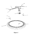
- Fig. 1 shows an exploded view of an illumination device 200 with an installation structure 100 according to an embodiment of the present invention.
- the illumination device 200 comprises a first mounting plate 1 which is configured in a disk shape and can be provided with a light source of the illumination device 200, and the first mounting plate 1 is further provided with a first assembling unit 11 and a second assembling unit 12, wherein the first assembling unit 11 and the second assembling unit 12 can be provided on the circumferential edge of the first mounting plate 1, and the first assembling unit 11 and the second assembling unit 12 can be installed and fixed on the first mounting plate 1 with for instance bolts 24, and wherein the light source can be configured as an LED light source or conventional fluorescent light source.
- the first assembling unit 11 and the second assembling unit 12 are arranged separately, opposite to each other, on the first mounting plate 1, and a line connecting the first assembling unit 11 and the second assembling unit 12 preferably can pass through the center of the first mounting plate 1 configured in a disk shape, in this way a distance between the first mounting plate 11 and the second mounting plate 12 can be configured to be the largest as much as possible.
- the installation structure 100 comprises a second mounting plate 2.
- a first installation portion 21 of the second mounting plate 2 can be firstly inserted into the first assembling unit 11 which has been already mounted to the first mounting plate 1, and the first mounting plate 1 is rotated around the first assembling unit 11 relative to the second mounting plate 2 in a clockwise or anticlockwise direction.
- the first mounting plate 1 and the second mounting plate 2 respectively can be configured to be made of a rigid material such as metal or resin plastic, wherein the first assembling unit 11 is preferably configured as a plug-in part such that the first installation portion 21 provided at one free end of the second mounting plate 2 can be inserted into the part to form partial connection of the first mounting plate 1 with the second mounting plate 2.
- the second assembling unit 12 is preferably configured as a snap-on part which can have a lateral opening after being assembled to the first mounting plate 1, that is, for instance, the opening can be configured to be oriented to a clockwise direction or an anticlockwise direction of the first mounting plate 1. According to the position of the second assembling unit 12 on the first mounting plate 1 and the orientation of the opening of the second assembling unit 12 configured, rotation directions of the first mounting plate 1 relative to the second mounting plate 2 will not be the same when the first mounting plate 1 is connected with the second mounting plate 2, but when the first mounting plate 1 is removed from the second mounting plate 2, the rotation direction of the first mounting plate 1 will be opposite to the direction when the first mounting plate 1 is installed.
- the second installation portion 22 is always snapped on the first assembling unit 11, for instance, in a circumferential direction of the first mounting plate 1 from a side of the first assembling unit 11.
- the second mounting plate 2 can be provided with assembling holes 23, and can be fixed to the mounting position using for example bolts passing through the assembling holes 23 via guide blocks.
- Fig. 1 further shows a first power connector 31 which can be provided on the first mounting plate 1 and a second power connector 32 which can be provided on the second mounting plate 2, wherein the first power connector 31 can be configured as a plug or a socket, and the second power connector 32 can be correspondingly configured as a socket or a plug in accordance with the first power connector 31.
- the first power connector 31 preferably is arranged on a surface of the first mounting plate 1 oriented to the second mounting plate 2, and the second power connector 32 further can be provided between the first mounting plate 1 and the second mounting plate 2, in this way, after the mechanical connection between the first mounting plate 1 and the second mounting plate 2 is completed, with the aid of the rotation movement of the first mounting plate 1 relative to the second mounting plate 2, the first power connector 31 can be connected to and form electric connection with the second power connector 32, wherein as the first mounting plate 1 is rotated around the first assembling unit 11, the first power connector 31 approaches the second power connector 32 from a side of the second mounting plate 2 and, as a result, is connected to the second power connector 32.
- Fig. 2 shows a schematic diagram of the installation structure 100 according to an embodiment of the present invention.
- the installation structure 100 comprises the second mounting plate 2 configured as a strip sheet.
- the second mounting plate 2 is configured in an elongated strip shape, and preferably has a length equal to or greater than a distance between the first assembling unit 11 and the second assembling unit 12.
- the second mounting plate 2 comprises installation portions, i.e. first installation portion 21 and second installation portion 22, preferably arranged at two free ends thereof,.
- the first installation portion 21 and the second installation portion 22 are respectively configured to be bent in a direction away from a plane defined by a main body of the second mounting plate 2, and preferably, the first installation portion 21 and the second installation portion 22 are enabled to be bent towards the first mounting plate 1, consequently, a space which can receive other devices such as electronic devices is formed between the first mounting plate 1 and the second mounting plate 2 after the second mounting plate 2 being installed onto the first mounting plate 1, and the electrical devices can be powered via wires 25 arranged on the second mounting plate 2, and wherein in cases where the length of the second mounting plate 2 is configured to be larger or far larger than the distance between the first assembling unit 11 and the second assembling unit 12, the first installation portion 21 and the second installation portion 22 can be preferably configured on the second mounting plate 2 and away from the two free ends of the second mounting plate 2.
- the first installation portion 21 when the first installation portion 21 is arranged at the free end of the second mounting plate 2, the first installation portion 21 can be configured with an fool-proof structure, for example, a wall structure 211 configured being vertical on the main body of the first installation portion 21.
- the second installation portion 22 In order to be capable of connecting the second installation portion 22 to the second assembling unit 12 on a side of the second assembling unit 12, and structurally distinguishing the second installation portion 22 from the first installation portion 21, the second installation portion 22 also can be configured with an fool-proof structure, for example, a barb structure 212 configured being vertical on the main body of the second installation portion 22.
- Fig. 3 shows a top view of the illumination device 200 installed with the installation structure 100 according to an embodiment of the present invention.
- Fig. 2 after installation of the first mounting plate 1 on the second mounting plate 2, not only mechanical connection between the first mounting plate 1 and the second mounting plate 2 is formed, but also electrical connection between the first mounting plate 1 and the second mounting plate 2 is formed at the same time through the electrical connection between the first power connector 31 arranged on the first mounting plate 1 and the second power connector 32 arranged on the second mounting plate 2.
- the illumination device 200 according to the present invention is installed and connected with the help of the installation structure 100, it is achieved not only fixing of the illumination device 200 to a mounting position, but also the electric connection of the illumination device 200.
Landscapes
- Engineering & Computer Science (AREA)
- General Engineering & Computer Science (AREA)
- Non-Portable Lighting Devices Or Systems Thereof (AREA)
Abstract
Description
- The present invention relates to an installation structure for fixing an illumination device and an illumination device comprising the installation structure, and an installation method for fixing the illumination device.
- The short circuit failure may occur when the conventional illumination device and LED illumination device are installed and maintained, wherein for installation of the illumination device, professional technical personnel and special tools are usually needed in the installation operation, and in order to suitably install and fix the illumination device on for instance the ceiling board, a lot of time and energy are cost. Besides, when non-professional personnel perform the installation and if the installation is inappropriate or failed, not only the normal use of the illumination device will be influenced or the normal service lifetime of the illumination device is reduced, but also potential safety accidents may occur.
- At present, for instance in order to install the conventional illumination device, such as an incandescent lamp or a fluorescent lamp, onto the ceiling board, respective parts of the illumination device should be firstly carefully connected mechanically, and when the illumination device is fixed onto the ceiling board, wires should be manually processed, and connected to the illumination device with a special tool so as to form electric connection. Furthermore, for instance, in order to install the LED illumination device onto the ceiling board, the cover of the LED illumination device must be opened such that the normal installation operation can be carried out, and this also will make the installation of the illumination device more difficult.
- In order to solve the above technical problems, the present invention provides a novel installation structure for fixing the illumination device and an illumination device comprising the installation structure, and an installation method for fixing the illumination device. With the installation structure and the installation method according to the present invention, the illumination device could be installed and fixed conveniently and quickly to a mounting position, moreover, the installation structure has a simple structure and a low cost, is easy to manufacture, and can be quickly installed or removed by any user without professional technical personnel. Furthermore, the light source of the illumination device having this installation structure can be changed simply according to user's requirement, and the device can be maintained easily by various users.
- One of the objects of the present invention is achieved via such an installation structure for fixing an illumination device, wherein the illumination device comprises a first mounting plate at least carrying a light source of the illumination device, wherein the installation structure comprises a second mounting plate, and the first mounting plate comprises a first assembling unit and a second assembling unit which are arranged opposite to each other on the first mounting plate, the second mounting plate comprises a first installation portion and a second installation portion, wherein the first installation portion is plugged into the first assembling unit, and through the first mounting plate rotating relative to the second mounting plate the second installation portion is locked in or unlocked from the second assembling unit. According to the installation structure in the present invention, after the second mounting plate being fixed to a mounting position such as ceiling or walls, the illumination device is fixed to the mounting position in a manner of a mechanical connection by installing or fixing the first mounting plate or the assembled illumination device having the first mounting plate to the second mounting plate. Such installation structure is simple, and the illumination device can be fixed to for instance the ceiling or the wall by means of the installation structure through quite simple operation steps.
- According to an embodiment of the present invention, preferably, the second installation portion is configured to be capable of being locked in or unlocked from the second assembling unit in a removable manner in a circumferential direction of the first mounting plate. According to such solution, the second installation portion can approach to the second assembling unit with the function of rotation from a side of the second assembling unit or in a circumferential direction of the first mounting plate, and thus can be mechanically connected with the second assembling unit in a removable manner.
- According to an embodiment of the present invention, preferably, the first mounting plate is rotated relative to the second assembling unit around a rotation axis perpendicular to the first mounting plate and extending through the first assembling unit. By means of the installation of the first assembling unit and the first installation portion, i.e. the first mounting plate partially forming connection with the second mounting plate, through the rotation of the first mounting plate around the above rotation axis, the second assembling unit arranged on the first mounting plate approaches, with the function of the rotation, and finally removably connect to the second installation portion of the second mounting plate.
- According to one example of the present invention, preferably, the first assembling unit is configured as a plug-in part, and the second assembling unit is configured as a snap-on part. The first assembling unit configured as a plug-in part enables the first installation portion of the second mounting plate to be connected to the first assembling unit of the first mounting plate in an insertion manner, and in cooperation with the rotation movement of the first mounting plate relative to the second mounting plate, the second assembling unit of the first mounting plate can be snapped on the second installation portion of the second mounting plate, for instance in a lateral direction of the second assembling unit or in a circumferential direction of the first mounting plate.
- Advantageously, the first installation portion is arranged at a first free end of the second mounting plate, the second installation portion is arranged at a second free end of the second mounting plate opposite to the first free end, and the first installation portion and the second installation portion are respectively configured to be bent in a direction away from a plane defined by a main body of the second mounting plate. According to such configuration, while the manufacturing material of the second mounting plate is saved, it can facilitate insertion of the first installation portion into the first assembling unit, and the second installation portion also can be easily snapped on the second assembling unit when the first mounting plate is rotated.
- Preferably, the first installation portion and the second installation portion are respectively configured to be bent towards the first mounting plate. According to such solution, space which can receive other devices related to the illumination device or the installation structure, such as electrical connection devices, is present between the second mounting plate and the first mounting plate after the second mounting plate being installed onto the first mounting plate, which makes it easy to fully use the space between the installation structure and the illumination device and simplify the structure of the installation structure.
- Preferably, the second mounting plate is made of a strip sheet. The second mounting plate configured as strip sheet can save the material and the cost of the installation structure, provides a structure which does not require a large space, and facilitates mechanical connection of the second mounting plate with the first mounting plate using the rotation movement of the first mounting plate relative to the second assembling plate.
- Another object of the present invention is accomplished via such an illumination device that comprises the installation structure as the above, and the illumination device further comprises a first power connector arranged on the first mounting plate and a second power connector arranged on the second mounting plate, wherein the first power connector and the second power connector could be engaged or disengaged so that an electrical connection therebetween could be formed or disconnected. According to such configuration, the electric connection of the illumination device having the installation structure is completed when the mechanical connection between the first mounting plate and the second mounting plate is completed, such that it is easier to achieve the electrical function of the illumination device in the installation without additional electric wiring.
- According to one example of the present invention, the first power connector and the second power connector are configured to be capable of being engaged so as to form an electric connection or being disengaged so as to disconnect the electric connection when the first mounting plate is rotated relative to the second mounting plate. The first power connector, by means of the rotation movement of the first mounting plate relative to the second mounting plate, can be connected to the second power connector without other connection actions, so as to achieve the electric connection of the illumination device.
- Preferably, the first power connector is configured as a plug or a socket, and the second power connector is configured as a socket or a plug. According to such configuration, the first power connector can be directly inserted into the second power connector with the rotation movement of the first mounting plate relative to the second mounting plate, and an electric connection and a mechanical connection of the two connectors is achieved.
- The present invention further relates to an installation method for fixing an illumination device comprising a first mounting plate, comprising: 1) fixing a second mounting plate of an installation structure for fixing the illumination device to a mounting position; 2) a first assembling unit and a second assembling unit which are arranged opposite to each other being provided on the first mounting plate, plugging a first installation portion of the second mounting plate into the first assembling unit; and 3) rotating the first mounting plate relative to the second mounting plate around a rotation axis perpendicular to the first mounting plate and extending through the first assembling unit, and locking the second installation portion of the second mounting plate in the second assembling unit or releasing the locking connection from the second assembling unit in a removable manner. According to the installation method for fixing the illumination device in the present invention, any user can quickly and simply fix the illumination device to a mounting position without professional technical personnel.
- According to the installation method for fixing the illumination device in the present invention, the second installation portion is locked in or unlocked from the second assembling unit in a removable manner in a circumferential direction of the first mounting plate. The electrical connection of the illumination device is achieved when the mechanical connection of the first mounting plate and the second mounting plate is achieved.
- The accompanying drawings constitute a part of the present Description and are used to provide further understanding of the present invention. Such accompanying drawings illustrate the embodiments of the present invention and are used to describe the principles of the present invention together with the Description. In the accompanying drawings the same components are represented by the same reference numbers. As shown in the drawings:
-
Fig. 1 shows an exploded view of an illumination device with an installation structure according to an embodiment of the present invention; -
Fig. 2 shows a schematic diagram of an installation structure according to an embodiment of the present invention; and -
Fig. 3 shows a top view of the illumination device installed with the installation structure according to an embodiment of the present invention. -
Fig. 1 shows an exploded view of anillumination device 200 with aninstallation structure 100 according to an embodiment of the present invention. As shown inFig. 1 , theillumination device 200 comprises a first mounting plate 1 which is configured in a disk shape and can be provided with a light source of theillumination device 200, and the first mounting plate 1 is further provided with a first assemblingunit 11 and a second assemblingunit 12, wherein the first assemblingunit 11 and the second assemblingunit 12 can be provided on the circumferential edge of the first mounting plate 1, and the first assemblingunit 11 and the second assemblingunit 12 can be installed and fixed on the first mounting plate 1 with forinstance bolts 24, and wherein the light source can be configured as an LED light source or conventional fluorescent light source. Preferably, the first assemblingunit 11 and the second assemblingunit 12 are arranged separately, opposite to each other, on the first mounting plate 1, and a line connecting the first assemblingunit 11 and the second assemblingunit 12 preferably can pass through the center of the first mounting plate 1 configured in a disk shape, in this way a distance between thefirst mounting plate 11 and thesecond mounting plate 12 can be configured to be the largest as much as possible. - The
installation structure 100 comprises asecond mounting plate 2. When the first mounting plate 1 is installed to thesecond mounting plate 2, for instance, afirst installation portion 21 of thesecond mounting plate 2 can be firstly inserted into the first assemblingunit 11 which has been already mounted to the first mounting plate 1, and the first mounting plate 1 is rotated around the first assemblingunit 11 relative to thesecond mounting plate 2 in a clockwise or anticlockwise direction. The first mounting plate 1 and thesecond mounting plate 2 respectively can be configured to be made of a rigid material such as metal or resin plastic, wherein the first assemblingunit 11 is preferably configured as a plug-in part such that thefirst installation portion 21 provided at one free end of thesecond mounting plate 2 can be inserted into the part to form partial connection of the first mounting plate 1 with thesecond mounting plate 2. The second assemblingunit 12 is preferably configured as a snap-on part which can have a lateral opening after being assembled to the first mounting plate 1, that is, for instance, the opening can be configured to be oriented to a clockwise direction or an anticlockwise direction of the first mounting plate 1. According to the position of the second assemblingunit 12 on the first mounting plate 1 and the orientation of the opening of the second assemblingunit 12 configured, rotation directions of the first mounting plate 1 relative to thesecond mounting plate 2 will not be the same when the first mounting plate 1 is connected with thesecond mounting plate 2, but when the first mounting plate 1 is removed from thesecond mounting plate 2, the rotation direction of the first mounting plate 1 will be opposite to the direction when the first mounting plate 1 is installed. Nevertheless, after thefirst installation portion 21 is inserted into the first assemblingunit 11, when the first mounting plate 1 is rotated relative to thesecond mounting plate 2, thesecond installation portion 22 is always snapped on the first assemblingunit 11, for instance, in a circumferential direction of the first mounting plate 1 from a side of the first assemblingunit 11. - In order to fix the
second mounting plate 2 to a position where it is to be fixed, for example the ceiling or the wall, thesecond mounting plate 2 can be provided with assemblingholes 23, and can be fixed to the mounting position using for example bolts passing through the assemblingholes 23 via guide blocks. -
Fig. 1 further shows afirst power connector 31 which can be provided on the first mounting plate 1 and asecond power connector 32 which can be provided on thesecond mounting plate 2, wherein thefirst power connector 31 can be configured as a plug or a socket, and thesecond power connector 32 can be correspondingly configured as a socket or a plug in accordance with thefirst power connector 31. Besides, thefirst power connector 31 preferably is arranged on a surface of the first mounting plate 1 oriented to thesecond mounting plate 2, and thesecond power connector 32 further can be provided between the first mounting plate 1 and thesecond mounting plate 2, in this way, after the mechanical connection between the first mounting plate 1 and thesecond mounting plate 2 is completed, with the aid of the rotation movement of the first mounting plate 1 relative to thesecond mounting plate 2, thefirst power connector 31 can be connected to and form electric connection with thesecond power connector 32, wherein as the first mounting plate 1 is rotated around the first assemblingunit 11, thefirst power connector 31 approaches thesecond power connector 32 from a side of thesecond mounting plate 2 and, as a result, is connected to thesecond power connector 32. -
Fig. 2 shows a schematic diagram of theinstallation structure 100 according to an embodiment of the present invention. Theinstallation structure 100 comprises thesecond mounting plate 2 configured as a strip sheet. Thesecond mounting plate 2 is configured in an elongated strip shape, and preferably has a length equal to or greater than a distance between the first assemblingunit 11 and the second assemblingunit 12. Thesecond mounting plate 2 comprises installation portions, i.e.first installation portion 21 andsecond installation portion 22, preferably arranged at two free ends thereof,. Thefirst installation portion 21 and thesecond installation portion 22 are respectively configured to be bent in a direction away from a plane defined by a main body of thesecond mounting plate 2, and preferably, thefirst installation portion 21 and thesecond installation portion 22 are enabled to be bent towards the first mounting plate 1, consequently, a space which can receive other devices such as electronic devices is formed between the first mounting plate 1 and thesecond mounting plate 2 after thesecond mounting plate 2 being installed onto the first mounting plate 1, and the electrical devices can be powered viawires 25 arranged on thesecond mounting plate 2, and wherein in cases where the length of thesecond mounting plate 2 is configured to be larger or far larger than the distance between the first assemblingunit 11 and the second assemblingunit 12, thefirst installation portion 21 and thesecond installation portion 22 can be preferably configured on thesecond mounting plate 2 and away from the two free ends of thesecond mounting plate 2. Besides, when thefirst installation portion 21 is arranged at the free end of thesecond mounting plate 2, thefirst installation portion 21 can be configured with an fool-proof structure, for example, awall structure 211 configured being vertical on the main body of thefirst installation portion 21. In order to be capable of connecting thesecond installation portion 22 to the second assemblingunit 12 on a side of the second assemblingunit 12, and structurally distinguishing thesecond installation portion 22 from thefirst installation portion 21, thesecond installation portion 22 also can be configured with an fool-proof structure, for example, abarb structure 212 configured being vertical on the main body of thesecond installation portion 22. -
Fig. 3 shows a top view of theillumination device 200 installed with theinstallation structure 100 according to an embodiment of the present invention. As shown inFig. 2 , after installation of the first mounting plate 1 on thesecond mounting plate 2, not only mechanical connection between the first mounting plate 1 and thesecond mounting plate 2 is formed, but also electrical connection between the first mounting plate 1 and thesecond mounting plate 2 is formed at the same time through the electrical connection between thefirst power connector 31 arranged on the first mounting plate 1 and thesecond power connector 32 arranged on thesecond mounting plate 2. Thereby, when theillumination device 200 according to the present invention is installed and connected with the help of theinstallation structure 100, it is achieved not only fixing of theillumination device 200 to a mounting position, but also the electric connection of theillumination device 200. - The above is merely preferred embodiments of the present invention but not to limit the present invention. For the person skilled in the art, the present invention may have various alterations and changes. Any alterations, equivalent substitutions, improvements, within the spirit and principle of the present invention, should be covered in the protection scope of the present invention.
-
- 1
- first mounting plate
- 2
- second mounting plate
- 11
- first assembling unit
- 12
- second assembling unit
- 21
- first installation portion
- 22
- second installation portion
- 23
- assembling hole
- 24
- bolt
- 25
- wire
- 31
- first power connector
- 32
- second power connector
- 211
- wall structure
- 212
- barb structure
- 100
- installation structure
- 200
- illumination device
Claims (12)
- An installation structure (100) for fixing an illumination device (200) comprising a first mounting plate (1) at least carrying a light source of the illumination device (200), characterized in that the installation structure (100) comprises a second mounting plate (2), and the first mounting plate (1) comprises a first assembling unit (11) and a second assembling unit (12) which are arranged opposite to each other on the first mounting plate (1), the second mounting plate (2) comprises a first installation portion (21) and a second installation portion (22), wherein the first installation portion (21) is plugged into the first assembling unit (11), and the second installation portion (22) is locked in or unlocked from the second assembling unit (12) by rotating the first mounting plate relative to the second mounting plate.
- The installation structure (100) according to claim 1, characterized in that the second installation portion (22) is configured to be capable of being locked in or unlocked from the second assembling unit (12) in a removable manner in a circumferential direction of the first mounting plate (1).
- The installation structure (100) according to claim 1, characterized in that the first mounting plate (1) is rotated relative to the second assembling unit (12) around a rotation axis perpendicular to the first mounting plate (1) and extending through the first assembling unit (11).
- The installation structure (100) according to claim 1, characterized in that the first assembling unit (11) is configured as a plug-in part, and the second assembling unit (12) is configured as a snap-on part.
- The installation structure (100) according to any one of claims 1-4, characterized in that the first installation portion (21) is arranged at a first free end of the second mounting plate (2), the second installation portion (22) is arranged at a second free end of the second mounting plate (2) opposite to the first free end, and the first installation portion (21) and the second installation portion (22) are respectively configured to be bent in a direction away from a plane defined by a main body of the second mounting plate (2).
- The installation structure (100) according to claim 5, characterized in that the first installation portion (21) and the second installation portion (22) are respectively configured to be bent towards the first mounting plate (1).
- The installation structure (100) according to claim 1, characterized in that the second mounting plate (2) is made of a strip sheet.
- An illumination device (200), characterized in that the illumination device (200) comprises the installation structure (100) according to any one of claims 1-7, and the illumination device (200) further comprises a first power connector (31) arranged on the first mounting plate (1) and a second power connector (32) arranged on the second mounting plate (2), wherein the first power connector (31) and the second power connector (32) could be engaged or disengaged so that an electrical connection therebetween could be formed or disconnected.
- The illumination device (200) according to claim 8, characterized in that the first power connector (31) and the second power connector (32) are configured to be capable of being engaged so as to form an electric connection or being disengaged so as to disconnect the electric connection when the first mounting plate (1) is rotated relative to the second mounting plate (2).
- The illumination device (200) according to claim 8, characterized in that the first power connector (31) is configured as a plug or a socket, and the second power connector (32) is configured as a socket or a plug.
- An installation method for fixing an illumination device (200) comprising a first mounting plate (1), characterized by comprising:1) fixing a second mounting plate (2) of an installation structure (100) for fixing the illumination device (200) to a mounting position;2) a first assembling unit (11) and a second assembling unit (12) which are arranged opposite to each other being provided on the first mounting plate (1), plugging a first installation portion (21) of the second mounting plate (2) into the first assembling unit (11); and3) rotating the first mounting plate (1) relative to the second mounting plate (2) around a rotation axis perpendicular to the first mounting plate (1) and extending through the first assembling unit (11), and locking the second installation portion (22) of the second mounting plate (2) in the second assembling unit (12) or releasing the locking connection from the second assembling unit (12) in a removable manner.
- The method according to claim 11, characterized in that the second installation portion (22) is locked in or unlocked from the second assembling unit (12) in a removable manner in a circumferential direction of the first mounting plate (1).
Applications Claiming Priority (1)
| Application Number | Priority Date | Filing Date | Title |
|---|---|---|---|
| CN201410077213.4A CN104896429B (en) | 2014-03-04 | 2014-03-04 | Mounting structure, lighting device and its installation method including the mounting structure |
Publications (2)
| Publication Number | Publication Date |
|---|---|
| EP2916065A1 true EP2916065A1 (en) | 2015-09-09 |
| EP2916065B1 EP2916065B1 (en) | 2017-06-21 |
Family
ID=52627019
Family Applications (1)
| Application Number | Title | Priority Date | Filing Date |
|---|---|---|---|
| EP15156741.9A Active EP2916065B1 (en) | 2014-03-04 | 2015-02-26 | Installation structure, illumination device comprising the installation structure and installation method thereof |
Country Status (2)
| Country | Link |
|---|---|
| EP (1) | EP2916065B1 (en) |
| CN (1) | CN104896429B (en) |
Cited By (3)
| Publication number | Priority date | Publication date | Assignee | Title |
|---|---|---|---|---|
| CN105810112A (en) * | 2016-05-13 | 2016-07-27 | 深圳市艾比森光电股份有限公司 | Front maintenance structure of small-spacing LED display screen |
| KR102023123B1 (en) * | 2019-03-05 | 2019-09-20 | 엘이디라이팅 주식회사 | one-touch fastening device for luminaires |
| US11359780B1 (en) * | 2021-08-05 | 2022-06-14 | Dong Guan Jia Sheng Lighting Technology Co., Ltd. China | Ceiling lamp bracket assembly without using screws |
Citations (6)
| Publication number | Priority date | Publication date | Assignee | Title |
|---|---|---|---|---|
| FR2455202A1 (en) * | 1978-12-26 | 1980-11-21 | Philips Ind Commerciale | Fixture for plastics or metal section to support - uses rotatable bracket to rotate section, esp. for electrical conduit fitting to ceiling |
| EP0370825A2 (en) * | 1988-11-25 | 1990-05-30 | Trudy M. Hudson | Light fixture connector |
| WO2008134424A2 (en) * | 2007-04-24 | 2008-11-06 | Lumination Llc | Led perimeter lighting system |
| US20120026744A1 (en) * | 2010-07-30 | 2012-02-02 | Koninklijke Philips Electronics N.V. | Mounting assembly |
| EP2495492A2 (en) * | 2011-03-04 | 2012-09-05 | Panasonic Corporation | Illumination device |
| US20130208489A1 (en) * | 2012-02-14 | 2013-08-15 | Hunter Industries, Inc. | Landscape Light Fixtures with Water Drainage and Twist and Lock Mounting Bracket Assembly |
Family Cites Families (1)
| Publication number | Priority date | Publication date | Assignee | Title |
|---|---|---|---|---|
| DE102010009608A1 (en) * | 2010-02-27 | 2011-09-01 | Abb Ag | Flush-mounted LED light, especially ceiling light |
-
2014
- 2014-03-04 CN CN201410077213.4A patent/CN104896429B/en not_active Expired - Fee Related
-
2015
- 2015-02-26 EP EP15156741.9A patent/EP2916065B1/en active Active
Patent Citations (6)
| Publication number | Priority date | Publication date | Assignee | Title |
|---|---|---|---|---|
| FR2455202A1 (en) * | 1978-12-26 | 1980-11-21 | Philips Ind Commerciale | Fixture for plastics or metal section to support - uses rotatable bracket to rotate section, esp. for electrical conduit fitting to ceiling |
| EP0370825A2 (en) * | 1988-11-25 | 1990-05-30 | Trudy M. Hudson | Light fixture connector |
| WO2008134424A2 (en) * | 2007-04-24 | 2008-11-06 | Lumination Llc | Led perimeter lighting system |
| US20120026744A1 (en) * | 2010-07-30 | 2012-02-02 | Koninklijke Philips Electronics N.V. | Mounting assembly |
| EP2495492A2 (en) * | 2011-03-04 | 2012-09-05 | Panasonic Corporation | Illumination device |
| US20130208489A1 (en) * | 2012-02-14 | 2013-08-15 | Hunter Industries, Inc. | Landscape Light Fixtures with Water Drainage and Twist and Lock Mounting Bracket Assembly |
Cited By (3)
| Publication number | Priority date | Publication date | Assignee | Title |
|---|---|---|---|---|
| CN105810112A (en) * | 2016-05-13 | 2016-07-27 | 深圳市艾比森光电股份有限公司 | Front maintenance structure of small-spacing LED display screen |
| KR102023123B1 (en) * | 2019-03-05 | 2019-09-20 | 엘이디라이팅 주식회사 | one-touch fastening device for luminaires |
| US11359780B1 (en) * | 2021-08-05 | 2022-06-14 | Dong Guan Jia Sheng Lighting Technology Co., Ltd. China | Ceiling lamp bracket assembly without using screws |
Also Published As
| Publication number | Publication date |
|---|---|
| CN104896429B (en) | 2019-08-20 |
| CN104896429A (en) | 2015-09-09 |
| EP2916065B1 (en) | 2017-06-21 |
Similar Documents
| Publication | Publication Date | Title |
|---|---|---|
| US11799255B2 (en) | Receptacle socket assembly for lighting equipment | |
| CN102170723B (en) | solid-state lighting system | |
| CN104930474B (en) | A lighting fixture | |
| EP2924815B1 (en) | Electrical device with a mounting interface and an electrical module | |
| EP2958198A1 (en) | Wiring fixture | |
| CN103513738A (en) | Power supply module assembly of server | |
| EP2916065B1 (en) | Installation structure, illumination device comprising the installation structure and installation method thereof | |
| WO2014090190A1 (en) | Lighting and back panel apparatus thereof | |
| EP2345840A2 (en) | Connector terminal for lamps | |
| CN206770167U (en) | Compressor | |
| US10165676B2 (en) | Circuit board system | |
| CN102405565B (en) | Electrical connection terminals for guiding conductors through walls | |
| CN212644321U (en) | Convenient modular wall-mounted device and wall-mounted electrical equipment | |
| CN104633605B (en) | Shell structure and lamps and lanterns with the shell structure | |
| CN205592721U (en) | Line lamp and power connection thereof | |
| CN105202495A (en) | Installing module and lighting fitting assembly | |
| CN219955225U (en) | Connector, track power supply and track lamp | |
| CN204922883U (en) | Installing module , lamps and lanterns combination | |
| US11879622B2 (en) | Driver for driving a light engine of a luminaire | |
| JP6469721B2 (en) | Assembly for transmitting power to or receiving power from a ceiling grid having an electrical function | |
| WO2014006941A1 (en) | Lighting apparatus | |
| CN204141524U (en) | A kind of erecting device and comprise the light fixture of this erecting device | |
| CN214153242U (en) | Bolt connection structure and plug | |
| KR20150137501A (en) | Lamp base apparatus with non-rotating isolation structure and Lamp using the same | |
| CN111059492A (en) | Convenient modular wall-mounted device and wall-mounted electrical equipment |
Legal Events
| Date | Code | Title | Description |
|---|---|---|---|
| PUAI | Public reference made under article 153(3) epc to a published international application that has entered the european phase |
Free format text: ORIGINAL CODE: 0009012 |
|
| AK | Designated contracting states |
Kind code of ref document: A1 Designated state(s): AL AT BE BG CH CY CZ DE DK EE ES FI FR GB GR HR HU IE IS IT LI LT LU LV MC MK MT NL NO PL PT RO RS SE SI SK SM TR |
|
| AX | Request for extension of the european patent |
Extension state: BA ME |
|
| 17P | Request for examination filed |
Effective date: 20160309 |
|
| RBV | Designated contracting states (corrected) |
Designated state(s): AL AT BE BG CH CY CZ DE DK EE ES FI FR GB GR HR HU IE IS IT LI LT LU LV MC MK MT NL NO PL PT RO RS SE SI SK SM TR |
|
| GRAP | Despatch of communication of intention to grant a patent |
Free format text: ORIGINAL CODE: EPIDOSNIGR1 |
|
| RIC1 | Information provided on ipc code assigned before grant |
Ipc: F21V 21/02 20060101AFI20170116BHEP |
|
| INTG | Intention to grant announced |
Effective date: 20170214 |
|
| GRAS | Grant fee paid |
Free format text: ORIGINAL CODE: EPIDOSNIGR3 |
|
| GRAA | (expected) grant |
Free format text: ORIGINAL CODE: 0009210 |
|
| AK | Designated contracting states |
Kind code of ref document: B1 Designated state(s): AL AT BE BG CH CY CZ DE DK EE ES FI FR GB GR HR HU IE IS IT LI LT LU LV MC MK MT NL NO PL PT RO RS SE SI SK SM TR |
|
| REG | Reference to a national code |
Ref country code: GB Ref legal event code: FG4D |
|
| REG | Reference to a national code |
Ref country code: CH Ref legal event code: EP |
|
| REG | Reference to a national code |
Ref country code: IE Ref legal event code: FG4D |
|
| REG | Reference to a national code |
Ref country code: AT Ref legal event code: REF Ref document number: 903296 Country of ref document: AT Kind code of ref document: T Effective date: 20170715 |
|
| REG | Reference to a national code |
Ref country code: DE Ref legal event code: R096 Ref document number: 602015003147 Country of ref document: DE |
|
| REG | Reference to a national code |
Ref country code: CH Ref legal event code: NV Representative=s name: BOVARD AG PATENT- UND MARKENANWAELTE, CH |
|
| REG | Reference to a national code |
Ref country code: NL Ref legal event code: MP Effective date: 20170621 |
|
| PG25 | Lapsed in a contracting state [announced via postgrant information from national office to epo] |
Ref country code: FI Free format text: LAPSE BECAUSE OF FAILURE TO SUBMIT A TRANSLATION OF THE DESCRIPTION OR TO PAY THE FEE WITHIN THE PRESCRIBED TIME-LIMIT Effective date: 20170621 Ref country code: NO Free format text: LAPSE BECAUSE OF FAILURE TO SUBMIT A TRANSLATION OF THE DESCRIPTION OR TO PAY THE FEE WITHIN THE PRESCRIBED TIME-LIMIT Effective date: 20170921 Ref country code: LT Free format text: LAPSE BECAUSE OF FAILURE TO SUBMIT A TRANSLATION OF THE DESCRIPTION OR TO PAY THE FEE WITHIN THE PRESCRIBED TIME-LIMIT Effective date: 20170621 Ref country code: HR Free format text: LAPSE BECAUSE OF FAILURE TO SUBMIT A TRANSLATION OF THE DESCRIPTION OR TO PAY THE FEE WITHIN THE PRESCRIBED TIME-LIMIT Effective date: 20170621 Ref country code: GR Free format text: LAPSE BECAUSE OF FAILURE TO SUBMIT A TRANSLATION OF THE DESCRIPTION OR TO PAY THE FEE WITHIN THE PRESCRIBED TIME-LIMIT Effective date: 20170922 |
|
| REG | Reference to a national code |
Ref country code: LT Ref legal event code: MG4D |
|
| PG25 | Lapsed in a contracting state [announced via postgrant information from national office to epo] |
Ref country code: RS Free format text: LAPSE BECAUSE OF FAILURE TO SUBMIT A TRANSLATION OF THE DESCRIPTION OR TO PAY THE FEE WITHIN THE PRESCRIBED TIME-LIMIT Effective date: 20170621 Ref country code: NL Free format text: LAPSE BECAUSE OF FAILURE TO SUBMIT A TRANSLATION OF THE DESCRIPTION OR TO PAY THE FEE WITHIN THE PRESCRIBED TIME-LIMIT Effective date: 20170621 Ref country code: LV Free format text: LAPSE BECAUSE OF FAILURE TO SUBMIT A TRANSLATION OF THE DESCRIPTION OR TO PAY THE FEE WITHIN THE PRESCRIBED TIME-LIMIT Effective date: 20170621 Ref country code: SE Free format text: LAPSE BECAUSE OF FAILURE TO SUBMIT A TRANSLATION OF THE DESCRIPTION OR TO PAY THE FEE WITHIN THE PRESCRIBED TIME-LIMIT Effective date: 20170621 Ref country code: BG Free format text: LAPSE BECAUSE OF FAILURE TO SUBMIT A TRANSLATION OF THE DESCRIPTION OR TO PAY THE FEE WITHIN THE PRESCRIBED TIME-LIMIT Effective date: 20170921 |
|
| PG25 | Lapsed in a contracting state [announced via postgrant information from national office to epo] |
Ref country code: EE Free format text: LAPSE BECAUSE OF FAILURE TO SUBMIT A TRANSLATION OF THE DESCRIPTION OR TO PAY THE FEE WITHIN THE PRESCRIBED TIME-LIMIT Effective date: 20170621 Ref country code: CZ Free format text: LAPSE BECAUSE OF FAILURE TO SUBMIT A TRANSLATION OF THE DESCRIPTION OR TO PAY THE FEE WITHIN THE PRESCRIBED TIME-LIMIT Effective date: 20170621 Ref country code: RO Free format text: LAPSE BECAUSE OF FAILURE TO SUBMIT A TRANSLATION OF THE DESCRIPTION OR TO PAY THE FEE WITHIN THE PRESCRIBED TIME-LIMIT Effective date: 20170621 Ref country code: SK Free format text: LAPSE BECAUSE OF FAILURE TO SUBMIT A TRANSLATION OF THE DESCRIPTION OR TO PAY THE FEE WITHIN THE PRESCRIBED TIME-LIMIT Effective date: 20170621 |
|
| REG | Reference to a national code |
Ref country code: FR Ref legal event code: PLFP Year of fee payment: 4 |
|
| PG25 | Lapsed in a contracting state [announced via postgrant information from national office to epo] |
Ref country code: IS Free format text: LAPSE BECAUSE OF FAILURE TO SUBMIT A TRANSLATION OF THE DESCRIPTION OR TO PAY THE FEE WITHIN THE PRESCRIBED TIME-LIMIT Effective date: 20171021 Ref country code: SM Free format text: LAPSE BECAUSE OF FAILURE TO SUBMIT A TRANSLATION OF THE DESCRIPTION OR TO PAY THE FEE WITHIN THE PRESCRIBED TIME-LIMIT Effective date: 20170621 Ref country code: PL Free format text: LAPSE BECAUSE OF FAILURE TO SUBMIT A TRANSLATION OF THE DESCRIPTION OR TO PAY THE FEE WITHIN THE PRESCRIBED TIME-LIMIT Effective date: 20170621 Ref country code: ES Free format text: LAPSE BECAUSE OF FAILURE TO SUBMIT A TRANSLATION OF THE DESCRIPTION OR TO PAY THE FEE WITHIN THE PRESCRIBED TIME-LIMIT Effective date: 20170621 |
|
| REG | Reference to a national code |
Ref country code: DE Ref legal event code: R097 Ref document number: 602015003147 Country of ref document: DE |
|
| PLBE | No opposition filed within time limit |
Free format text: ORIGINAL CODE: 0009261 |
|
| STAA | Information on the status of an ep patent application or granted ep patent |
Free format text: STATUS: NO OPPOSITION FILED WITHIN TIME LIMIT |
|
| PG25 | Lapsed in a contracting state [announced via postgrant information from national office to epo] |
Ref country code: DK Free format text: LAPSE BECAUSE OF FAILURE TO SUBMIT A TRANSLATION OF THE DESCRIPTION OR TO PAY THE FEE WITHIN THE PRESCRIBED TIME-LIMIT Effective date: 20170621 |
|
| PGFP | Annual fee paid to national office [announced via postgrant information from national office to epo] |
Ref country code: CH Payment date: 20180216 Year of fee payment: 4 |
|
| 26N | No opposition filed |
Effective date: 20180322 |
|
| PGFP | Annual fee paid to national office [announced via postgrant information from national office to epo] |
Ref country code: IT Payment date: 20180228 Year of fee payment: 4 |
|
| PG25 | Lapsed in a contracting state [announced via postgrant information from national office to epo] |
Ref country code: SI Free format text: LAPSE BECAUSE OF FAILURE TO SUBMIT A TRANSLATION OF THE DESCRIPTION OR TO PAY THE FEE WITHIN THE PRESCRIBED TIME-LIMIT Effective date: 20170621 |
|
| PG25 | Lapsed in a contracting state [announced via postgrant information from national office to epo] |
Ref country code: MC Free format text: LAPSE BECAUSE OF FAILURE TO SUBMIT A TRANSLATION OF THE DESCRIPTION OR TO PAY THE FEE WITHIN THE PRESCRIBED TIME-LIMIT Effective date: 20170621 |
|
| REG | Reference to a national code |
Ref country code: IE Ref legal event code: MM4A |
|
| REG | Reference to a national code |
Ref country code: BE Ref legal event code: MM Effective date: 20180228 |
|
| PG25 | Lapsed in a contracting state [announced via postgrant information from national office to epo] |
Ref country code: LU Free format text: LAPSE BECAUSE OF NON-PAYMENT OF DUE FEES Effective date: 20180226 |
|
| PG25 | Lapsed in a contracting state [announced via postgrant information from national office to epo] |
Ref country code: IE Free format text: LAPSE BECAUSE OF NON-PAYMENT OF DUE FEES Effective date: 20180226 |
|
| PG25 | Lapsed in a contracting state [announced via postgrant information from national office to epo] |
Ref country code: BE Free format text: LAPSE BECAUSE OF NON-PAYMENT OF DUE FEES Effective date: 20180228 |
|
| REG | Reference to a national code |
Ref country code: CH Ref legal event code: PL |
|
| GBPC | Gb: european patent ceased through non-payment of renewal fee |
Effective date: 20190226 |
|
| PG25 | Lapsed in a contracting state [announced via postgrant information from national office to epo] |
Ref country code: LI Free format text: LAPSE BECAUSE OF NON-PAYMENT OF DUE FEES Effective date: 20190228 Ref country code: CH Free format text: LAPSE BECAUSE OF NON-PAYMENT OF DUE FEES Effective date: 20190228 |
|
| PG25 | Lapsed in a contracting state [announced via postgrant information from national office to epo] |
Ref country code: GB Free format text: LAPSE BECAUSE OF NON-PAYMENT OF DUE FEES Effective date: 20190226 Ref country code: MT Free format text: LAPSE BECAUSE OF NON-PAYMENT OF DUE FEES Effective date: 20180226 |
|
| PG25 | Lapsed in a contracting state [announced via postgrant information from national office to epo] |
Ref country code: IT Free format text: LAPSE BECAUSE OF NON-PAYMENT OF DUE FEES Effective date: 20190226 |
|
| REG | Reference to a national code |
Ref country code: DE Ref legal event code: R082 Ref document number: 602015003147 Country of ref document: DE Representative=s name: BOEHMERT & BOEHMERT ANWALTSPARTNERSCHAFT MBB -, DE Ref country code: DE Ref legal event code: R081 Ref document number: 602015003147 Country of ref document: DE Owner name: SITECO GMBH, DE Free format text: FORMER OWNER: OSRAM GMBH, 80807 MUENCHEN, DE |
|
| PG25 | Lapsed in a contracting state [announced via postgrant information from national office to epo] |
Ref country code: TR Free format text: LAPSE BECAUSE OF FAILURE TO SUBMIT A TRANSLATION OF THE DESCRIPTION OR TO PAY THE FEE WITHIN THE PRESCRIBED TIME-LIMIT Effective date: 20170621 |
|
| PG25 | Lapsed in a contracting state [announced via postgrant information from national office to epo] |
Ref country code: PT Free format text: LAPSE BECAUSE OF FAILURE TO SUBMIT A TRANSLATION OF THE DESCRIPTION OR TO PAY THE FEE WITHIN THE PRESCRIBED TIME-LIMIT Effective date: 20170621 |
|
| PG25 | Lapsed in a contracting state [announced via postgrant information from national office to epo] |
Ref country code: HU Free format text: LAPSE BECAUSE OF FAILURE TO SUBMIT A TRANSLATION OF THE DESCRIPTION OR TO PAY THE FEE WITHIN THE PRESCRIBED TIME-LIMIT; INVALID AB INITIO Effective date: 20150226 Ref country code: CY Free format text: LAPSE BECAUSE OF FAILURE TO SUBMIT A TRANSLATION OF THE DESCRIPTION OR TO PAY THE FEE WITHIN THE PRESCRIBED TIME-LIMIT Effective date: 20170621 Ref country code: MK Free format text: LAPSE BECAUSE OF NON-PAYMENT OF DUE FEES Effective date: 20170621 |
|
| PG25 | Lapsed in a contracting state [announced via postgrant information from national office to epo] |
Ref country code: AL Free format text: LAPSE BECAUSE OF FAILURE TO SUBMIT A TRANSLATION OF THE DESCRIPTION OR TO PAY THE FEE WITHIN THE PRESCRIBED TIME-LIMIT Effective date: 20170621 |
|
| REG | Reference to a national code |
Ref country code: AT Ref legal event code: PC Ref document number: 903296 Country of ref document: AT Kind code of ref document: T Owner name: SITECO GMBH, DE Effective date: 20210305 |
|
| REG | Reference to a national code |
Ref country code: AT Ref legal event code: UEP Ref document number: 903296 Country of ref document: AT Kind code of ref document: T Effective date: 20170621 |
|
| PGFP | Annual fee paid to national office [announced via postgrant information from national office to epo] |
Ref country code: FR Payment date: 20230217 Year of fee payment: 9 |
|
| PG25 | Lapsed in a contracting state [announced via postgrant information from national office to epo] |
Ref country code: FR Free format text: LAPSE BECAUSE OF NON-PAYMENT OF DUE FEES Effective date: 20240229 |
|
| PG25 | Lapsed in a contracting state [announced via postgrant information from national office to epo] |
Ref country code: FR Free format text: LAPSE BECAUSE OF NON-PAYMENT OF DUE FEES Effective date: 20240229 |
|
| PGFP | Annual fee paid to national office [announced via postgrant information from national office to epo] |
Ref country code: DE Payment date: 20260217 Year of fee payment: 12 |
|
| PGFP | Annual fee paid to national office [announced via postgrant information from national office to epo] |
Ref country code: AT Payment date: 20260216 Year of fee payment: 12 |