JP6469721B2 - Assembly for transmitting power to or receiving power from a ceiling grid having an electrical function - Google Patents
Assembly for transmitting power to or receiving power from a ceiling grid having an electrical function Download PDFInfo
- Publication number
- JP6469721B2 JP6469721B2 JP2016559985A JP2016559985A JP6469721B2 JP 6469721 B2 JP6469721 B2 JP 6469721B2 JP 2016559985 A JP2016559985 A JP 2016559985A JP 2016559985 A JP2016559985 A JP 2016559985A JP 6469721 B2 JP6469721 B2 JP 6469721B2
- Authority
- JP
- Japan
- Prior art keywords
- connector
- grid
- power
- attached
- assembly
- Prior art date
- Legal status (The legal status is an assumption and is not a legal conclusion. Google has not performed a legal analysis and makes no representation as to the accuracy of the status listed.)
- Expired - Fee Related
Links
Images

Classifications
-
- H—ELECTRICITY
- H01—ELECTRIC ELEMENTS
- H01R—ELECTRICALLY-CONDUCTIVE CONNECTIONS; STRUCTURAL ASSOCIATIONS OF A PLURALITY OF MUTUALLY-INSULATED ELECTRICAL CONNECTING ELEMENTS; COUPLING DEVICES; CURRENT COLLECTORS
- H01R25/00—Coupling parts adapted for simultaneous co-operation with two or more identical counterparts, e.g. for distributing energy to two or more circuits
- H01R25/14—Rails or bus-bars constructed so that the counterparts can be connected thereto at any point along their length
- H01R25/142—Their counterparts
-
- H—ELECTRICITY
- H01—ELECTRIC ELEMENTS
- H01R—ELECTRICALLY-CONDUCTIVE CONNECTIONS; STRUCTURAL ASSOCIATIONS OF A PLURALITY OF MUTUALLY-INSULATED ELECTRICAL CONNECTING ELEMENTS; COUPLING DEVICES; CURRENT COLLECTORS
- H01R25/00—Coupling parts adapted for simultaneous co-operation with two or more identical counterparts, e.g. for distributing energy to two or more circuits
- H01R25/14—Rails or bus-bars constructed so that the counterparts can be connected thereto at any point along their length
- H01R25/147—Low voltage devices, i.e. safe to touch live conductors
Landscapes
- Details Of Connecting Devices For Male And Female Coupling (AREA)
Description
本願は、概して、電気的機能を有する天井グリッドへの送電または当該天井グリッドからの受電のためのアセンブリに関し、特に、1つ以上の業界標準電気コネクタまたはインタフェースを介する低電圧の直流電流(DC)の供給に関する。 The present application relates generally to assemblies for transmitting power to or receiving power from a ceiling grid with electrical functionality, and in particular, low voltage direct current (DC) via one or more industry standard electrical connectors or interfaces. Related to the supply.
アメリカの発電所、送電線および変電所と、家庭、企業および工場とを結ぶ電力網は、高電圧の交流電流(AC)で全面的に稼働している。しかし、これらの建物において実際には低電圧の直流電流(DC)で稼働する電気機器の割合は、増加している。それらの機器には、次に限定されるものではないが、デジタルディスプレイ、リモートコントローラ、感圧コントローラ、送信機、受信機、タイマー、発光ダイオード(LED)、オーディオアンプ、マイクロプロセッサ、他のデジタル電子機器、および、スマートフォン、タブレット、ラップトップコンピュータ等の充電可能または使い捨て可能なバッテリを利用する事実上全ての製品が含まれる。 The power grid connecting American power plants, transmission lines and substations with homes, businesses and factories is fully operational with high voltage alternating current (AC). However, in these buildings, the proportion of electrical equipment that is actually operating with low voltage direct current (DC) is increasing. These devices include but are not limited to digital displays, remote controllers, pressure sensitive controllers, transmitters, receivers, timers, light emitting diodes (LEDs), audio amplifiers, microprocessors, and other digital electronics. Includes virtually all products that utilize devices and rechargeable or disposable batteries such as smartphones, tablets, laptop computers and the like.
低DC電圧を利用する機器の設置は、一般的に、DC電圧源から一対の電線が届く位置に限られる。低DC電圧機器の配置および駆動について、多様性を向上することが望まれている。具体的には、建物の内部環境、特に天井環境に、既存のシステムの欠点を無くしてDC電源等の電気的機能を持たせることが求められている。 The installation of equipment that uses a low DC voltage is generally limited to a position where a pair of electric wires can reach from a DC voltage source. It is desirable to improve diversity in the placement and drive of low DC voltage equipment. Specifically, it is required that the internal environment of a building, particularly the ceiling environment, have an electrical function such as a DC power supply without the disadvantages of existing systems.
表面を覆うシステム等に使用される従来の天井グリッド構造(フレームワーク)は、メイングリッド要素を含み、それらの間のクロスグリッド要素がメイングリッド要素に対して交差している。メインおよびクロス要素は、パネル、照明器具、スピーカ、行動探知機等の機器または部品を挿入または支持することが可能な多角形の開口を形成している。従来の構造システムにおいて、照明部品等の機器に電力を供給する既知の装置は、電線管、ケーブルトレイ、電気的ジャンクションを介する “必要に応じた”ポイント・ツー・ポイント原理(point-to-point basis)に主に基づいて、天井グリッド構造の裏の空間に配置されたディスクリートワイヤまたはケーブルを配索する手段を利用する。この既知の装置によれば、必要とされる電線のネットワークが、天井グリッド構造の裏の限られた空間を占有し、保守または変更することが困難であるという欠点に悩まされる。さらに、一般的に得られる電力レベルは、訓練を受け、免許を受け、および/または、認可を受けた者でなければ、作業を行うのに安全ではない。 A conventional ceiling grid structure (framework) used for a surface covering system or the like includes main grid elements, and a cross grid element between them intersects the main grid element. The main and cross elements form a polygonal opening into which devices or components such as panels, luminaires, speakers, behavior detectors and the like can be inserted or supported. In conventional structural systems, known devices for supplying power to lighting components and other equipment are “point-to-point” points-to-point via conduits, cable trays and electrical junctions. Based on the basis), a means of routing discrete wires or cables arranged in the space behind the ceiling grid structure is utilized. With this known device, the required wire network occupies the limited space behind the ceiling grid structure and suffers from the disadvantage that it is difficult to maintain or modify. Furthermore, the power levels that are generally obtained are not safe to perform unless they are trained, licensed, and / or authorized.
また、低DC電圧源に接続された電化天井グリッド構造システムを提供するものとして、米国特許第7997910号に記載のものが知られている。そのシステムにおける各グリッド要素は、相対する極性を有するとともに各グリッド要素の相対する面に配置された一対の導電体またはバスを、その長さ方向に沿って支持する。電気グリッドコネクタまたは電源タップは、1つ以上のグリッド要素に取り付けられ、一対の導体に電気的に接続されている。一対の電線は、低DC電圧を機器に直接供給するために、グリッドコネクタから遠隔の電子機器に延びている。 Moreover, what is described in US Pat. No. 7,997,910 is known for providing an electrified ceiling grid structure system connected to a low DC voltage source. Each grid element in the system supports a pair of conductors or buses along their length that have opposite polarities and are disposed on opposite faces of each grid element. An electrical grid connector or power strip is attached to one or more grid elements and is electrically connected to a pair of conductors. A pair of wires extend from the grid connector to a remote electronic device to provide a low DC voltage directly to the device.
既知の電化天井グリッド構造システムは有益であるが、現在使用されている技術は、電線の長さを決定付ける遠隔の電気機器へ電線を直結することについて、いささか制約されていた。こうして、電線の長さは、各機器のためにカスタマイズされていた。異なる位置に在る他の機器に接続することが求められた場合は、電線の長さを変更しなければならなかった。より長くすることが必要な場合には、他の電線のセットを用意してグリッドコネクタに結線しなければならなかった。さらに、既知のシステムにおける電線は、フレームワーク平面に対して全方向から満足いく程度に接続できなかった。 While known electrified ceiling grid construction systems are beneficial, the technology currently used is somewhat constrained in connecting the wires directly to the remote electrical equipment that determines the length of the wires. Thus, the length of the wire was customized for each device. When it was required to connect to other equipment at a different location, the length of the wire had to be changed. When it was necessary to make it longer, another set of wires had to be prepared and connected to the grid connector. Furthermore, the wires in the known system could not be satisfactorily connected from all directions to the framework plane.
したがって、電線と遠隔の機器との間の接続について多様性および接続性をより向上させることを可能にすることが望ましい。 Therefore, it is desirable to be able to further improve the diversity and connectivity of connections between electrical wires and remote devices.
添付の図は、明細書の一部として組み込まれて明細書の一部を形成し、請求項に係る発明を含む概念の実施形態を詳しく説明するために役立ち、実施形態の様々な原理および利点を説明するものであり、図において同種の参照番号は、下記の詳細な説明とともに、別々の図を通して同一または機能的に類似する要素を示している。 The accompanying drawings, which are incorporated in and form a part of the specification, serve to explain in detail embodiments of the concept, including the claimed invention, and the various principles and advantages of the embodiments. In the figures, like reference numerals designate identical or functionally similar elements throughout the different views, along with the following detailed description.
当業者は、図中の要素は簡潔かつ明瞭に示したものであって、必ずしも原寸通りに描かれたものではないことを把握するであろう。例えば、図中のいくつかの要素の寸法を、本発明の実施形態の理解を深め易くするために、他の要素に対して誇張して差し支えない。 Those skilled in the art will recognize that the elements in the figures are shown in a concise and clear manner and are not necessarily drawn to scale. For example, the dimensions of some elements in the figures may be exaggerated with respect to other elements to facilitate an understanding of the embodiments of the present invention.
アセンブリ構成部品は、図面において必要に応じて従来の記号を用いて表されており、図面は、本明細書に記載した利益を得る当業者に容易に発見されるべき詳細な開示が曖昧にならないように、本発明の実施形態の理解に適切な特有の詳細のみを示している。 Assembly components are represented in the drawings using conventional symbols where appropriate, and the drawings do not obscure the detailed disclosure that should be readily discovered by those of ordinary skill in the art having the benefit described herein. Thus, only specific details relevant to an understanding of embodiments of the present invention are shown.
<詳細な説明>
本発明の1つの特徴に従って、アセンブリは、グリッド構造の電気的機能を有するグリッド要素と電気機器との間において電力を供給する。アセンブリは、グリッド要素に在る一対の導電体に対して電気的に接触するためのグリッドコネクタと、グリッドコネクタに取り付けられたアダプタとを備える。アダプタは、グリッドコネクタに電気的に接続された業界標準インタフェースを含む。そのインタフェースは、電源ケーブルの一端に在る電源コネクタを受け止めるように構成されており、電源ケーブルの他端は、電気機器に接続される。電気機器がDC電源装置である場合は、アセンブリはグリッド要素にDC電圧を供給する。電気機器がDC電力を消費する場合は、アセンブリは電気機器にDC電圧を供給する。適切な一インタフェースは、ユニバーサルシリアルバス(USB)プロトコル、バージョン1.0、2.0、または3.0である。USBインタフェースまたは端子のタイプには、標準Aプラグ/レセプタクル、標準Bプラグ/レセプタクル、マイクロAもしくはマイクロBプラグ/レセプタクル、および、ミニAもしくはミニBプラグ/レセプタクルが含まれる。
<Detailed explanation>
In accordance with one aspect of the present invention, the assembly provides power between the grid elements having the electrical function of the grid structure and the electrical equipment. The assembly includes a grid connector for making electrical contact to a pair of electrical conductors in the grid element, and an adapter attached to the grid connector. The adapter includes an industry standard interface electrically connected to the grid connector. The interface is configured to receive a power connector at one end of the power cable, and the other end of the power cable is connected to an electrical device. If the electrical device is a DC power supply, the assembly supplies a DC voltage to the grid element. If the electrical device consumes DC power, the assembly supplies a DC voltage to the electrical device. One suitable interface is the Universal Serial Bus (USB) protocol, version 1.0, 2.0, or 3.0. USB interface or terminal types include standard A plug / receptacle, standard B plug / receptacle, micro A or micro B plug / receptacle, and mini A or mini B plug / receptacle.
図面を参照すると、参照番号109は、概して、吊り天井を支持する電化グリッド構造の代表的なグリッド要素を特定している。グリッド要素が互いに直交する構造を有するいかなる装置も、本発明の技術を利用することができる。その構造は、装飾タイル、防音タイル、絶縁タイル、他の天井要素、カバー、もしくは、それらの組み合わせ、または、照明、暖房・換気・空調(HVAC)の通気口等の電力を消費する任意の電気機器、または、電源装置等の電気を供給する任意の電気機器を支持することができる。正と負のDC電圧の極性のために平坦化されたストリップ108および108’等の一対の導体またはバスが、グリッド要素109に、具体的にはその上部112に配置されている。ストリップ108および108’には、それらを所望の電圧で電気的に作動した状態にするために、電源装置(不図示)が接続される。
Referring to the drawings,
電気グリッドコネクタ120は、電源装置からストリップ108および108’に、またはストリップ108および108’から様々な低DC電圧消費機器に、DC電力をもたらすための手段を提供する。それらの機器には、次に限定されるものではないが、デジタルディスプレイ、リモートコントローラ、感圧コントローラ、送信機、受信機、タイマー、発光ダイオード(LED)、オーディオアンプ、マイクロプロセッサ、他のデジタル電子機器、および、スマートフォン、タブレット、ラップトップコンピュータ等の充電可能または使い捨て可能なバッテリを利用する事実上全ての製品が含まれる。LED照明、スピーカ、煙もしくは一酸化炭素検知器、無線アクセスポイント、静止画用もしくは動画用カメラ等の低電圧機器、または他の低電圧機器が、電化グリッド構造に取り付けられて、そのグリッド構造から電力を受けて動作することもできる。
The
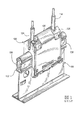
図2に最もよく見られるように、グリッドコネクタ120は、導電性を有する2つの電線圧着端子122および122’、非導電性の絶縁ハウジング124、並びに、外側のクランプ126を備えている。導電性を有する電線圧着端子122および122’の各々は、第1および第2接触部を含む。電線圧着端子122および122’の各々の第1接触部128は、弾性を有しており、取り付け時にグリッド要素109に配置されたストリップ108および108’に接触する、換言すれば軽く当たる接触ばね130を含む。圧着端子122および122’の各々の第2接触部132も、ストリップ108および108’に接触する。圧着端子122および122’の各々の第2接触部は、レセプタクル132であって、レセプタクル132には、グリッドコネクタ120へ低DC電圧を伝送するかグリッドコネクタ120からの低DC電圧を伝送する電線134が取り付け可能である。
As best seen in FIG. 2, the
絶縁ハウジング124は、柔軟でU字型であり、上部112を覆ってグリッド要素109に取り付けられている。ハウジング124は、電線圧着端子122および122’を、受け入れ、すなわち収納し、かつ、ストリップ108および108’を互いに対にするために適切な位置に並べる。グリッドコネクタ120がグリッド要素109に取り付けられているとき、電線圧着端子の第1接触部の各々は、ストリップ108および108’に接触している。電線圧着端子が絶縁ハウジング124の内壁に取り付けられているとき、絶縁ハウジングは、基本的に電線圧着端子を互いに隔離し、電線圧着端子同士が短絡することを防ぐ。
The insulating
外側のクランプ126は、硬くも多少柔軟な材料で形成され、絶縁ハウジング124上に留められている。クランプ126は、グリッド要素109にグリッドコネクタ120を取り付ける前に、ハウジング124に取り付けまたは予め組み立てることができるが、挿入力を最小にするために、少なくとも2つの他の方法でクランプ126を取り付けることができる。まず、挿入力を低くするために、グリッド要素109にハウジング124を完全に取り付けた後、クランプ126を取り付けることができる。これに代えて、クランプ126を、上がった位置にあるハウジング124に部分的に取り付け、その後、ハウジング124を全体的に適合した位置にしてから完全に取り付けることができ、それにより挿入力を低くすることができるが、ハウジング124にクランプ126を予め組み立てることが必要となる。
The
硬くも柔軟なクランプ126は、ストリップ108,108’との強固で電気的に安定した電気機械接続を確保するために、この他の方法で柔軟なU字状のハウジング124に強度を与える。また、クランプ126は、天井タイルまたは電気機器などの装置の取り付けおよび/または取り外しの際にグリッド要素109から外れることを防ぐのに十分に強固であることを確実にするのに貢献する。さらに、クランプ126の上部の随意的な傾斜面は、天井タイル等の装置をグリッド構造により形成された開口に挿入する際に当該装置にコネクタ120が干渉するとき、その挿入を容易にする。同様に、ハウジング124の底部またはパーチ(perch)の末端は、グリッドコネクタ120が偶発的に外れることを引き起こさないようにしながら、装置の取り外しを補助するための傾斜面を有している。
The stiff but
上述したように、従来技術において、遠隔の電気機器への電線134の直結は、電線134の長さを決定付けていた。電線の長さは、各機器のためにカスタマイズされていた。異なる位置に在る他の機器に接続することが求められた場合は、電線の長さを変更しなければならなかった。より長くすることが必要な場合には、他の電線のセットを用意してコネクタに結線しなければならなかった。さらに、既知のシステムにおける電線134は、フレームワーク平面に対して全方向から満足いく程度に接続できなかった。
As described above, in the prior art, the direct connection of the
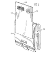
よって、本開示に従って、アダプタは、グリッドコネクタ120に取り付けられている。アダプタは、クランプ126に固定された支持プレート140と、そのプレート140に取り付けられて電線134を介してグリッドコネクタ120に電気的に接続された少なくとも1つの業界標準インタフェースまたは送受信兼用のコネクタとを含む。図2〜4で示すように、業界標準インタフェースは、ユニバーサルシリアルバス(USB)プロトコル、バージョン1.0、2.0、または3.0が好ましい。USBインタフェースまたはコネクタのタイプは、標準Aプラグ/レセプタクル、標準Bプラグ/レセプタクル、マイクロAまたはマイクロBプラグ/レセプタクル、およびミニAまたはミニBプラグ/レセプタクルを含む。USBレセプタクル142のUSB2.0標準Aタイプが図示され、略長方形のソケットを有している。このレセプタクル142は、図2の電源ケーブル148の末端に在るプラグ146等のUSBプラグによってキーボード、マウス、またはフラッシュドライブ等のコンピュータ周辺機器が接続されるコンピュータに頻繁に見られる。USBレセプタクルは、複数のピンを有し、それらの2つ、通常はピン1と4は、電線134に接続される電源ピンである。
Thus, in accordance with the present disclosure, the adapter is attached to the
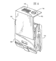
他のレセプタクル144は、プレート140に随意的に取り付けられており、業界標準の一般的な送受信兼用のコネクタを示している。図4において、プレート140は、レセプタクル142,144が横を向いている図3とは対照的に、レセプタクル142,144が屈曲部150に配置され上向きであるため、非平面的である。屈曲部150は、レセプタクルの方向づけにさらなる多様性をもたらすために、プレート140にヒンジ結合することもできる。
The
アダプタおよびグリッドコネクタ120が、グリッド要素109に取り付けられると、電源ケーブル148のUSBプラグ146は、レセプタクル142に簡単に挿入することができる。電源ケーブル148の反対側の末端がDC電源装置に接続されている場合は、アセンブリはグリッド要素109に対して任意の所望値でDC電圧を供給する。電源ケーブル148の反対側の末端がDC電力を消費する電気機器に接続されている場合は、アセンブリは電気機器にDC電圧を供給する。接続を簡潔にするために、異なる長さの電源ケーブルを用意することもできる。さらに、図3,4中のレセプタクル142,144の異なる方向づけにより、それらは、フレームワーク平面に対して全方向から満足いく程度に接続できる状態となる。
Once the adapter and
支持プレート140は、1つ以上の回路基板、および/または、低電圧が所定の限界値を超えないことを確実にするための電圧レギュレータ152(図2参照)等の1つ以上の電気部品を、簡便に支持することができる。例えば、低DC電圧は、100ワットで24VDCを超えないことが好ましく、レギュレータは、例えば、ツェナーダイオードおよび抵抗により構成され、限界を超えないことを保証することができる。電圧レギュレータ152は、任意の所望値に電流を制限する電流制限器を含むことができる。
The
上述の明細書には、具体的な実施形態が記載されている。しかし、当業者は、特許請求の範囲に記載されている発明の範囲から逸脱することなく様々な改良および変更を行うことができることを理解する。それに応じて、明細書および図面は、限定的意味ではなく例示として捉えられるべきであり、その全ての改良は、本開示の範囲内に含まれることを意味する。 Specific embodiments are described in the above specification. However, one of ordinary skill in the art appreciates that various modifications and changes can be made without departing from the scope of the invention as set forth in the claims below. Accordingly, the specification and drawings are to be regarded in an illustrative rather than a restrictive sense, all modifications being meant to be included within the scope of the present disclosure.
利益、利点、課題解決策、および、何らかの利益、利点、もしくは課題解決策を生み出すか顕著なものとすることができる任意の要素は、任意または全ての請求項について、重要な意味を持つ、要求されるべき、または必要不可欠な特徴もしくは要素として解釈されるべきではない。本発明は、本願の係属中に行われた任意の補正および発行された特許請求の範囲に等しい全てのものを含む添付の特許請求の範囲によってのみ規定される。 Benefits, advantages, problem solutions, and any element that can produce or make any benefit, advantage, or problem solution have a significant meaning for any or all claims Should not be construed as an essential feature or element. The invention is defined solely by the appended claims including any amendments made during the pendency of this application and all equivalents of those claims as issued.
さらに、この明細書において、第1、第2、上部、および、底部等の関係を示す用語は、ある実在物または作用と他の実在物または作用とを単に区別するために使用する場合もあり、それらの実在物または作用について現実の関係または順序を必ずしも要求または意味するものではない。“備える(comprises)”、“備えている(comprising)”、“有する(has)”、“有している(having)”、“含む(includes)”、“含んでいる(including)”、“包含する(contains)”、“包含している(containing)”、または、それらの他の変形は、要素のリストを備えるか有するか含むか包含する工程、方法、製品、または装置が、それらの要素のみを含むのではなく、明示的に挙げられていない他の要素、または、その工程、方法、製品、もしくは装置に固有の他の要素を含むことができるように、非排他的な包含に及ぶことを意図している。“〜を備える(comprises ... a)”、“〜を有する(has ... a)”、“〜を含む(includes ... a)”、または、“〜を包含する(contains ... a)”に続く要素は、その要素を備えるか有するか含むか包含する工程、方法、製品、または装置において、それ以上の制約は無く、追加の同一要素の存在を除外するものではない。“ある”("a"と"an")は、本明細書に別段の明示が無ければ、1つ以上と同義である。“実質的に(substantially)”、“基本的に(essentially)”、“およそ(approximately)”、“約(about)”、または、それらの他のバージョンは、当業者によって理解されるものに近いものとして定義され、その用語は、非限定的な一実施形態においては10%以内と、他の実施形態においては5%以内と、他の実施形態においては1%以内と、他の実施形態においては0.5%以内と定義される。本明細書で使用される“結合した(coupled)”は、必ずしも直接的な接続ではなく、必ずしも機械的な接続ではない。特定の方法で“構成”されている機器または構造は、少なくともその方法で構成されるだけでなく、挙げられていない方法で構成することもできる。 Further, in this specification, terms indicating the relationship such as first, second, top, and bottom may be used to simply distinguish one entity or action from another. Does not necessarily require or imply an actual relationship or order of such entities or actions. “Comprises”, “comprising”, “has”, “having”, “includes”, “including”, “ “Contains”, “containing”, or other variations thereof, includes, includes, includes or includes a list of elements, methods, products, or devices Including non-exclusive inclusions so that other elements not explicitly listed, or other elements specific to the process, method, product, or apparatus, may be included rather than including only elements Intended to extend. “Comprises ... a)”, “has (has ... a)”, “includes ... a”, or “contains .. The element following “a)” is not further constrained in the process, method, product or apparatus comprising, including or including that element and does not exclude the presence of additional identical elements. “A” (“a” and “an”) is synonymous with one or more unless otherwise specified herein. "Substantially", "essentially", "approximately", "about", or other versions thereof are close to those understood by those skilled in the art And the term is within 10% in one non-limiting embodiment, within 5% in other embodiments, within 1% in other embodiments, and in other embodiments. Is defined as within 0.5%. As used herein, “coupled” is not necessarily a direct connection and is not necessarily a mechanical connection. A device or structure that is “configured” in a particular way can be configured not only at least in that way, but also in ways not listed.
本願の要約は、読者が技術的開示の本質を迅速に把握することを可能にするために提供するものである。特許請求の範囲の意味の解釈または限定のために使用されるものではないという理解の下で提出したものである。さらに、前述の詳細な説明では、様々な特徴が、開示を効率的に行う目的で種々の実施形態においてグループ化されていることが見て取れる。本開示の方法は、請求項に係る実施形態が各請求項で明示的に引用したものよりも多くの特徴を必要とする意図を反映したものとして解釈されるべきものではない。むしろ、特許請求の範囲は、発明事項が開示した単一の実施形態の全ての特徴よりも少ないことを反映している。したがって、特許請求の範囲は、本明細書によって詳細な説明に組み込まれており、請求項に係る要旨は別々のものとして各請求項は独立している。 This summary is provided to enable the reader to quickly grasp the essence of technical disclosure. It is submitted with the understanding that it will not be used to interpret or limit the meaning of the claims. Moreover, in the foregoing detailed description, it can be seen that various features are grouped in various embodiments for the purpose of efficient disclosure. This method of disclosure is not to be interpreted as reflecting an intention that the claimed embodiments require more features than are expressly recited in each claim. Rather, the claims reflect that the invention is less than all the features of a single embodiment disclosed. Thus, the following claims are hereby incorporated into the detailed description, with each claim standing on its own as a separate subject matter.
108 ストリップ
109 グリッド要素
120 グリッドコネクタ
140 支持プレート
142 レセプタクル
144 レセプタクル
146 プラグ
148 電源ケーブル
150 屈曲部
152 電圧レギュレータ
108
Claims (8)
少なくとも1つのグリッド要素(109)を有するグリッド構造と、
前記少なくとも1つのグリッド要素(109)上にある、当該グリッド要素(109)に沿って延びている一対の直流導電体(108,108’)と、
前記少なくとも1つのグリッド要素(109)に取り付けられた絶縁ハウジング(124)と外側のクランプ(126)とを有するグリッドコネクタ(120)と、
前記外側のクランプ(126)に取り付けられ、当該外側のクランプ(126)から離れるように延びている支持プレート(140)と、
前記グリッドコネクタ(120)の上方で前記支持プレート(140)に取り付けられた直流コネクタ(142)とを備え、
前記グリッドコネクタ(120)が、前記絶縁ハウジング(124)上に前記外側のクランプ(126)が留められているときに前記少なくとも1つのグリッド要素(109)上にある前記直流導電体(108,108’)に対して電気的に接触するための一対の端子(122,122’)と、前記端子(122,122’)に接続されて当該端子(122,122’)から離れるように延びている一対の電線(134,134)とを有し、
前記直流コネクタ(142)が、前記電線(134,134)に接続されて、直流電源ケーブル(148)の一端に在る直流電源コネクタ(146)に電気的に接続されるように構成され、前記直流電源ケーブル(148)の他端が、前記電気機器に接続される
ことを特徴とするアセンブリ。 An assembly for transmitting and receiving DC power to and from electrical equipment,
A grid structure having at least one grid element (109);
A pair of DC conductors (108, 108 ') extending along the grid element (109) on the at least one grid element (109);
A grid connector (120) having an insulating housing (124) attached to the at least one grid element (109) and an outer clamp (126) ;
Wherein mounted on the outside of the clamp (126), a support plate extending away from the outer side of the clamp (126) and (140),
A DC connector (142) attached to the support plate (140) above the grid connector (120);
The DC conductor (108, 108), wherein the grid connector (120) is on the at least one grid element (109) when the outer clamp (126) is fastened on the insulating housing (124). ') And a pair of terminals (122, 122') for electrical contact, and connected to the terminals (122, 122 ') and extending away from the terminals (122, 122') A pair of wires (134, 134);
The DC connector (142) is connected to the electric wires (134, 134) and is electrically connected to a DC power connector (146) at one end of a DC power cable (148), The other end of the direct current power cable (148) is connected to the electric device.
ことを特徴とする請求項1に記載のアセンブリ。 The grid structure is located in a substantially horizontal framework plane, the support plate (140) is a substantially planar plate extending substantially perpendicular to the framework plane, and the DC connector (142) is The assembly according to claim 1, wherein the assembly is attached to the plate.
ことを特徴とする請求項1に記載のアセンブリ。 The grid structure is located in a substantially horizontal framework plane, and the support plate (140) is substantially planar with respect to the substantially planar upright support portion extending substantially perpendicular to the framework plane and the framework plane. The assembly according to claim 1, comprising a substantially planar upper support (150) extending in parallel, wherein the DC connector (142) is attached to the upper support (150).
ことを特徴とする請求項1に記載のアセンブリ。 The assembly of claim 1, wherein the DC connector (142) is a universal serial bus (USB) connector.
ことを特徴とする請求項1に記載のアセンブリ。 The DC power cable (148) is configured to transmit the power from the electrical device to the pair of conductors (108, 108 ') on the at least one grid element (109). The assembly according to claim 1, wherein
ことを特徴とする請求項1に記載のアセンブリ。 The DC power cable (148) is configured to transmit the power from the pair of conductors (108, 108 ') on the at least one grid element (109) to the electrical equipment. The assembly according to claim 1, wherein
ことを特徴とする請求項1に記載のアセンブリ。 The assembly of claim 1, further comprising a DC voltage regulator (152) attached to the support plate (140) for regulating a DC voltage at the DC connector (142).
ことを特徴とする請求項1に記載のアセンブリ。 The assembly according to claim 1, further comprising another DC connector (144) attached to the support plate (140) adjacent to the DC connector (142).
Applications Claiming Priority (5)
| Application Number | Priority Date | Filing Date | Title |
|---|---|---|---|
| US201461973459P | 2014-04-01 | 2014-04-01 | |
| US61/973,459 | 2014-04-01 | ||
| US14/587,379 US9425567B2 (en) | 2014-04-01 | 2014-12-31 | Assembly for conducting electrical power to or from electrically active ceiling grid |
| US14/587,379 | 2014-12-31 | ||
| PCT/US2015/014200 WO2015152989A1 (en) | 2014-04-01 | 2015-02-03 | Assembly for conducting electrical power to or from electrically active ceiling grid |
Publications (3)
| Publication Number | Publication Date |
|---|---|
| JP2017511575A JP2017511575A (en) | 2017-04-20 |
| JP2017511575A5 JP2017511575A5 (en) | 2017-11-16 |
| JP6469721B2 true JP6469721B2 (en) | 2019-02-13 |
Family
ID=54191662
Family Applications (1)
| Application Number | Title | Priority Date | Filing Date |
|---|---|---|---|
| JP2016559985A Expired - Fee Related JP6469721B2 (en) | 2014-04-01 | 2015-02-03 | Assembly for transmitting power to or receiving power from a ceiling grid having an electrical function |
Country Status (7)
| Country | Link |
|---|---|
| US (1) | US9425567B2 (en) |
| EP (1) | EP3127195A4 (en) |
| JP (1) | JP6469721B2 (en) |
| KR (1) | KR20160140841A (en) |
| CN (1) | CN106463898A (en) |
| CA (1) | CA2942922A1 (en) |
| WO (1) | WO2015152989A1 (en) |
Families Citing this family (1)
| Publication number | Priority date | Publication date | Assignee | Title |
|---|---|---|---|---|
| EP3757310A1 (en) * | 2019-06-28 | 2020-12-30 | Saint-Gobain Ecophon AB | Ceiling system |
Family Cites Families (30)
| Publication number | Priority date | Publication date | Assignee | Title |
|---|---|---|---|---|
| US3590135A (en) * | 1969-07-24 | 1971-06-29 | Gen Electric | Ceiling structure with integral power distribution means |
| US5158472A (en) * | 1989-02-21 | 1992-10-27 | Steelcase Inc. | Modular powerway for office furniture and the like |
| US6059582A (en) * | 1998-07-20 | 2000-05-09 | W.A.C. Lighting | Adaptor box for mounting fixture to low voltage track |
| US6869209B2 (en) * | 2000-07-28 | 2005-03-22 | Cooper Technologies Company | Assembly for a wedge base track lamp holder |
| JP2002313131A (en) * | 2001-04-18 | 2002-10-25 | Denso Corp | Lighting device |
| US6722918B2 (en) * | 2002-05-06 | 2004-04-20 | Lyall Assemblies, Inc. | Rail electrical connector system |
| US20060072302A1 (en) * | 2004-10-01 | 2006-04-06 | Chien Tseng L | Electro-luminescent (EL) illuminated wall plate device with push-tighten frame means |
| US8014170B2 (en) * | 2003-08-26 | 2011-09-06 | Belkin International, Inc. | Cable management device and method of cable management |
| US20080302033A1 (en) * | 2004-07-30 | 2008-12-11 | Insalaco Robert W | Power and Communication Distributions System Using Split Bus Rail Structure |
| US8232468B2 (en) * | 2004-08-04 | 2012-07-31 | Yamaha Corporation | Electronic musical apparatus for reproducing received music content |
| US7223122B2 (en) * | 2005-06-03 | 2007-05-29 | Belkin International, Inc. | Electrical connectivity system capable of being mounted to an object, and method of manufacturing same |
| US20070275594A1 (en) * | 2006-05-23 | 2007-11-29 | United Technologies Corporation | Multipurpose power center |
| JP2008084586A (en) * | 2006-09-26 | 2008-04-10 | Matsushita Electric Works Ltd | Ceiling-hung type information outlet |
| US7762821B2 (en) * | 2006-10-17 | 2010-07-27 | Worthington Armstrong Venture | Electrified ceiling framework |
| US7351075B1 (en) * | 2006-10-17 | 2008-04-01 | Awi Licensing Company | Electrified ceiling framework connectors |
| JP4966070B2 (en) * | 2007-03-30 | 2012-07-04 | パナソニック株式会社 | Wiring system |
| JP5113480B2 (en) * | 2007-10-16 | 2013-01-09 | パナソニック株式会社 | Duct-mounted PLC plug and its parent-child setting method |
| DE112009000697B4 (en) * | 2008-03-19 | 2021-08-12 | Vertiv Corporation | Customizable power strip |
| AU2009231581A1 (en) * | 2008-04-03 | 2009-10-08 | Belkin International, Inc. | Power management connection devices and related methods |
| US7997910B2 (en) * | 2008-04-15 | 2011-08-16 | Awi Licensing Company | Connectors for electrically active grid |
| US8146316B2 (en) * | 2008-11-26 | 2012-04-03 | Usg Interiors, Llc | Electrified ceiling grid |
| US8002586B2 (en) * | 2009-09-25 | 2011-08-23 | Pucline, Llc | Electrical power supplying device having a lower deck housing region for containing and concealing a plurality of electrical power adapters associated with a plurality of electrical appliances, and an upper deck housing region for supporting a ring-like power assembly having a central aperture and receiving the power plugs and/or power adapters of electrical appliances, while managing excess power cord length within a 3D volume passing through said central aperture |
| JP2011146186A (en) * | 2010-01-13 | 2011-07-28 | Toshiba Lighting & Technology Corp | Lighting duct |
| JP2012009261A (en) * | 2010-06-24 | 2012-01-12 | Panasonic Electric Works Co Ltd | Plug for wiring duct |
| JP2012010482A (en) * | 2010-06-24 | 2012-01-12 | Panasonic Electric Works Co Ltd | Wiring duct and electrical equipment for the same |
| US8535070B2 (en) | 2011-12-02 | 2013-09-17 | Tyco Electronics Corporation | Connector for electrified ceiling grid |
| US8506310B2 (en) | 2011-12-02 | 2013-08-13 | Tyco Electronics Corporation | Connector for electrified ceiling grid and method of installing the same |
| US8986021B2 (en) * | 2012-03-09 | 2015-03-24 | Ideal Industries, Inc. | Connector having a push-in termination for an electrically active grid |
| US8770993B2 (en) * | 2012-06-01 | 2014-07-08 | Tyco Electronics Corporation | Connector assembly with polarity correction/protection |
| BR102014012897A2 (en) * | 2013-05-31 | 2015-05-12 | Norman R Byrne | Low voltage power receptacle assembly for use in a modular electrical system |
-
2014
- 2014-12-31 US US14/587,379 patent/US9425567B2/en not_active Expired - Fee Related
-
2015
- 2015-02-03 KR KR1020167030257A patent/KR20160140841A/en active IP Right Grant
- 2015-02-03 JP JP2016559985A patent/JP6469721B2/en not_active Expired - Fee Related
- 2015-02-03 CA CA2942922A patent/CA2942922A1/en not_active Abandoned
- 2015-02-03 WO PCT/US2015/014200 patent/WO2015152989A1/en active Application Filing
- 2015-02-03 EP EP15772872.6A patent/EP3127195A4/en not_active Withdrawn
- 2015-02-03 CN CN201580017764.4A patent/CN106463898A/en active Pending
Also Published As
| Publication number | Publication date |
|---|---|
| EP3127195A1 (en) | 2017-02-08 |
| CA2942922A1 (en) | 2015-10-08 |
| CN106463898A (en) | 2017-02-22 |
| EP3127195A4 (en) | 2017-11-29 |
| WO2015152989A1 (en) | 2015-10-08 |
| US9425567B2 (en) | 2016-08-23 |
| JP2017511575A (en) | 2017-04-20 |
| KR20160140841A (en) | 2016-12-07 |
| US20150280382A1 (en) | 2015-10-01 |
Similar Documents
| Publication | Publication Date | Title |
|---|---|---|
| US8770993B2 (en) | Connector assembly with polarity correction/protection | |
| US8976541B2 (en) | Electrical power and data distribution apparatus | |
| CN101558539A (en) | Electrified ceiling framework connectors | |
| WO2013081914A1 (en) | Polarity protection for electrified grid and mating connector | |
| WO2005114916A2 (en) | Ac powered self organizing wireless node | |
| US8535070B2 (en) | Connector for electrified ceiling grid | |
| US20140103742A1 (en) | Connector having wireless control capabilities | |
| US8506310B2 (en) | Connector for electrified ceiling grid and method of installing the same | |
| US20170111978A1 (en) | Methods and apparatus for providing dc power for low voltage lighting | |
| US20150311698A1 (en) | Power strip, power plug, and power outlet | |
| WO2014090190A1 (en) | Lighting and back panel apparatus thereof | |
| JP6469721B2 (en) | Assembly for transmitting power to or receiving power from a ceiling grid having an electrical function | |
| EP2916065B1 (en) | Installation structure, illumination device comprising the installation structure and installation method thereof | |
| TW202005189A (en) | Electrical junction receptacle with magnetic electrical connectors | |
| US8864535B2 (en) | Poke-in contact with multiple contact sections to accept and terminate a respective wire from varied directions | |
| TW202119717A (en) | Usb outlet | |
| CN204852982U (en) | LED module | |
| CN210007038U (en) | kinds of extension socket | |
| CN102394430A (en) | Power outlet | |
| JP2017511575A5 (en) | ||
| AU2016101472A4 (en) | Power charger | |
| CN104747956A (en) | LED module |
Legal Events
| Date | Code | Title | Description |
|---|---|---|---|
| A521 | Request for written amendment filed |
Free format text: JAPANESE INTERMEDIATE CODE: A523 Effective date: 20171005 |
|
| A621 | Written request for application examination |
Free format text: JAPANESE INTERMEDIATE CODE: A621 Effective date: 20171005 |
|
| A977 | Report on retrieval |
Free format text: JAPANESE INTERMEDIATE CODE: A971007 Effective date: 20180821 |
|
| A131 | Notification of reasons for refusal |
Free format text: JAPANESE INTERMEDIATE CODE: A131 Effective date: 20180919 |
|
| A521 | Request for written amendment filed |
Free format text: JAPANESE INTERMEDIATE CODE: A523 Effective date: 20181214 |
|
| TRDD | Decision of grant or rejection written | ||
| A01 | Written decision to grant a patent or to grant a registration (utility model) |
Free format text: JAPANESE INTERMEDIATE CODE: A01 Effective date: 20190109 |
|
| A61 | First payment of annual fees (during grant procedure) |
Free format text: JAPANESE INTERMEDIATE CODE: A61 Effective date: 20190116 |
|
| R150 | Certificate of patent or registration of utility model |
Ref document number: 6469721 Country of ref document: JP Free format text: JAPANESE INTERMEDIATE CODE: R150 |
|
| LAPS | Cancellation because of no payment of annual fees |