EP2915681A1 - Non-pneumatic tire - Google Patents
Non-pneumatic tire Download PDFInfo
- Publication number
- EP2915681A1 EP2915681A1 EP13851636.4A EP13851636A EP2915681A1 EP 2915681 A1 EP2915681 A1 EP 2915681A1 EP 13851636 A EP13851636 A EP 13851636A EP 2915681 A1 EP2915681 A1 EP 2915681A1
- Authority
- EP
- European Patent Office
- Prior art keywords
- end section
- connecting plate
- ring
- tire
- curved
- Prior art date
- Legal status (The legal status is an assumption and is not a legal conclusion. Google has not performed a legal analysis and makes no representation as to the accuracy of the status listed.)
- Granted
Links
Images



Classifications
-
- B—PERFORMING OPERATIONS; TRANSPORTING
- B60—VEHICLES IN GENERAL
- B60B—VEHICLE WHEELS; CASTORS; AXLES FOR WHEELS OR CASTORS; INCREASING WHEEL ADHESION
- B60B9/00—Wheels of high resiliency, e.g. with conical interacting pressure-surfaces
- B60B9/02—Wheels of high resiliency, e.g. with conical interacting pressure-surfaces using springs resiliently mounted bicycle rims
- B60B9/04—Wheels of high resiliency, e.g. with conical interacting pressure-surfaces using springs resiliently mounted bicycle rims in leaf form
-
- B—PERFORMING OPERATIONS; TRANSPORTING
- B60—VEHICLES IN GENERAL
- B60C—VEHICLE TYRES; TYRE INFLATION; TYRE CHANGING; CONNECTING VALVES TO INFLATABLE ELASTIC BODIES IN GENERAL; DEVICES OR ARRANGEMENTS RELATED TO TYRES
- B60C7/00—Non-inflatable or solid tyres
- B60C7/10—Non-inflatable or solid tyres characterised by means for increasing resiliency
- B60C7/14—Non-inflatable or solid tyres characterised by means for increasing resiliency using springs
- B60C7/16—Non-inflatable or solid tyres characterised by means for increasing resiliency using springs of helical or flat coil form
- B60C7/18—Non-inflatable or solid tyres characterised by means for increasing resiliency using springs of helical or flat coil form disposed radially relative to wheel axis
-
- B—PERFORMING OPERATIONS; TRANSPORTING
- B60—VEHICLES IN GENERAL
- B60B—VEHICLE WHEELS; CASTORS; AXLES FOR WHEELS OR CASTORS; INCREASING WHEEL ADHESION
- B60B9/00—Wheels of high resiliency, e.g. with conical interacting pressure-surfaces
- B60B9/02—Wheels of high resiliency, e.g. with conical interacting pressure-surfaces using springs resiliently mounted bicycle rims
-
- B—PERFORMING OPERATIONS; TRANSPORTING
- B60—VEHICLES IN GENERAL
- B60B—VEHICLE WHEELS; CASTORS; AXLES FOR WHEELS OR CASTORS; INCREASING WHEEL ADHESION
- B60B9/00—Wheels of high resiliency, e.g. with conical interacting pressure-surfaces
- B60B9/02—Wheels of high resiliency, e.g. with conical interacting pressure-surfaces using springs resiliently mounted bicycle rims
- B60B9/08—Wheels of high resiliency, e.g. with conical interacting pressure-surfaces using springs resiliently mounted bicycle rims in flat coiled form
-
- B—PERFORMING OPERATIONS; TRANSPORTING
- B60—VEHICLES IN GENERAL
- B60B—VEHICLE WHEELS; CASTORS; AXLES FOR WHEELS OR CASTORS; INCREASING WHEEL ADHESION
- B60B9/00—Wheels of high resiliency, e.g. with conical interacting pressure-surfaces
- B60B9/26—Wheels of high resiliency, e.g. with conical interacting pressure-surfaces comprising resilient spokes
-
- B—PERFORMING OPERATIONS; TRANSPORTING
- B60—VEHICLES IN GENERAL
- B60C—VEHICLE TYRES; TYRE INFLATION; TYRE CHANGING; CONNECTING VALVES TO INFLATABLE ELASTIC BODIES IN GENERAL; DEVICES OR ARRANGEMENTS RELATED TO TYRES
- B60C7/00—Non-inflatable or solid tyres
- B60C7/10—Non-inflatable or solid tyres characterised by means for increasing resiliency
- B60C7/14—Non-inflatable or solid tyres characterised by means for increasing resiliency using springs
-
- B—PERFORMING OPERATIONS; TRANSPORTING
- B60—VEHICLES IN GENERAL
- B60C—VEHICLE TYRES; TYRE INFLATION; TYRE CHANGING; CONNECTING VALVES TO INFLATABLE ELASTIC BODIES IN GENERAL; DEVICES OR ARRANGEMENTS RELATED TO TYRES
- B60C7/00—Non-inflatable or solid tyres
- B60C7/24—Non-inflatable or solid tyres characterised by means for securing tyres on rim or wheel body
-
- B—PERFORMING OPERATIONS; TRANSPORTING
- B60—VEHICLES IN GENERAL
- B60C—VEHICLE TYRES; TYRE INFLATION; TYRE CHANGING; CONNECTING VALVES TO INFLATABLE ELASTIC BODIES IN GENERAL; DEVICES OR ARRANGEMENTS RELATED TO TYRES
- B60C7/00—Non-inflatable or solid tyres
- B60C7/10—Non-inflatable or solid tyres characterised by means for increasing resiliency
- B60C7/14—Non-inflatable or solid tyres characterised by means for increasing resiliency using springs
- B60C7/146—Non-inflatable or solid tyres characterised by means for increasing resiliency using springs extending substantially radially, e.g. like spokes
Definitions
- the present invention relates to a non-pneumatic tire in which pressurized air need not be filled upon use.
- Patent Document 1 a non-pneumatic tire as disclosed in the following Patent Document 1 is proposed.
- Patent Document 1 Japanese Unexamined Patent Application, First Publication No. 2011-156905
- the present invention is directed to provide a non-pneumatic tire capable of securing sufficient strength while limiting an increase in weight.
- the thickness of a maximum curved section having a largest central angle, in which bending deformation is largely generated to cause easy application of a load is maximized, and the thickness of a minimum curved section having a smallest central angle, in which bending deformation cannot be easily generated to cause difficulty in application of the load, is minimized. For this reason, sufficient strength can be easily secured while limiting an increase in weight.
- a non-pneumatic tire of a third aspect of the present invention in the first or second aspect, in the intermediate portions of the first connecting plate and the second connecting plate, the curved sections separately joined to first end section and the second end section protrude in opposite directions in the tire circumferential direction. For this reason, when an external force is applied to the non-pneumatic tire, the first connecting plate and the second connecting plate can be easily elastically deformed, and flexibility can be provided in the non-pneumatic tire to secure good ride comfort.
- a non-pneumatic tire of a fourth aspect of the present invention in any one of the first to third aspects, since the exterior body, the ring-shaped body and the plurality of connecting members are integrally formed with each other, when the non-pneumatic tire is assembled, even though both end sections of the plurality of connecting members are not separately connected to the exterior body and the ring-shaped body, it is sufficient if the ring-shaped body and the plurality of connecting members are mounted on the attachment body in a state in which they are integrally formed with each other, and thus manufacturing time can be reduced.
- the ring-shaped body and the plurality of connecting members are integrally formed with each other, for example, an increase in weight can be limited in comparison with the case in which both end sections of the connecting member, the exterior body and the ring-shaped body are connected using a fastening member or the like.
- connecting portions of the connecting member and the ring-shaped body are integrally formed with each other, stress concentration can be attenuated in comparison with a case in which both of them are connected using the fastening member or the like.
- a non-pneumatic tire 1 of the embodiment may be employed in a compact vehicle or the like that runs at a low speed, for example, electrically power scooters or the like defined by Japanese Industrial Standard JIS T 9208.
- the non-pneumatic tire 1 having a tire size of, for example, 3.00-8 will be described. As shown in Figs.
- the non-pneumatic tire 1 of the embodiment includes an attachment body 11 attached to an axle (not shown), a ring-shaped body 13 configured to surround the attachment body 11 from the outside in a tire radial direction, a plurality of connecting members 15 disposed between the attachment body 11 and the ring-shaped body 13 in a tire circumferential direction and configured to connect the attachment body 11 and the ring-shaped body 13 in a relatively elastically displaceable manner, and a tread member 16 disposed at an outer circumferential surface side of the ring-shaped body 13 throughout the entire circumference.
- the attachment body 11, the ring-shaped body 13 and the tread member 16 are disposed on the same axis as a common axis.
- the common axis is referred to as an axis O
- a direction along the axis O is referred to as a tire width direction H
- a direction perpendicular to the axis O is referred to as a tire radial direction
- a direction around the axis O is referred to as a tire circumferential direction.
- the attachment body 11, the ring-shaped body 13 and the tread member 16 are disposed such that central sections in the tire width direction H coincide with each other.
- the attachment body 11 includes a mounting rim section 17 on which a front end section of the axle is mounted, an outer ring section 18 configured to surround the mounting rim section 17 from the outside in the tire radial direction, and a plurality of ribs 19 configured to connect the mounting rim section 17 and the outer ring section 18.
- the mounting rim section 17, the outer ring section 18 and the ribs 19 are integrally formed of a metal material such as an aluminum alloy or the like.
- the mounting rim section 17 and the outer ring section 18 are formed in a cylindrical shape and disposed on the same axis as the axis O.
- the plurality of ribs 19 are point-symmetrically disposed with respect to the axis O.
- a plurality of key groove sections 18a concaved inward in the tire radial direction and extending in the tire width direction H are formed at an outer circumferential surface of the outer ring section 18 at intervals in the tire circumferential direction.
- the key groove sections 18a are opened at only first side of both ends in the tire width direction H and closed at the second side.
- a plurality of hole arrays 18c in each of which a plurality of weight-reducing holes passing in the tire radial direction are disposed at intervals in the tire width direction H, are formed at a portion of the outer ring section 18 disposed between the key groove sections 18a which are adjacent in the tire circumferential direction at intervals in the tire circumferential direction.
- weight-reducing holes 19a passing in the tire width direction H are also formed in the ribs 19.
- a cylindrical exterior body 12 is fitted onto the attachment body 11.
- a plurality of ridge sections 12a protruding inward in the tire radial direction and extending throughout the entire length in the tire width direction H are disposed at an inner circumferential surface of the exterior body 12 at intervals in the tire circumferential direction.
- the ridge sections 12a are fitted into the key groove sections 18a of the attachment body 11.
- the exterior body 12 is fixed to the attachment body 11 as the plate member 28 is fixed into the concave section 18b in a state in which the ridge section 12a is fitted into the key groove section 18a. In this state, the ridge section 12a is sandwiched between the plate member 28 and a bottom wall surface of the concave section 18b in the tire width direction H.
- a pair of side wall surfaces opposite to each other in the tire circumferential direction are perpendicular to a bottom wall surface.
- the pair of side wall surfaces standing upward from the inner circumferential surface of the exterior body 12 are perpendicular to a top wall surface directed inward in the tire radial direction.
- sizes in the tire circumferential direction of the ridge section 12a and the key groove section 18a are equal to each other.
- the ring-shaped body 13 has a larger size, i.e., a larger width in the tire width direction H, than the exterior body 12, and in the example shown, the ring-shaped body 13 is formed in a cylindrical shape.
- the plurality of first connecting plates 21 are disposed in the tire circumferential direction at one position in the tire width direction H (first side in the tire width direction H), and the plurality of second connecting plates 22 are disposed in the tire circumferential direction at another position in the tire width direction H (the second side in the tire width direction H) different from the one position in the tire width direction H. That is, the plurality of first connecting plates 21 are disposed in the tire circumferential direction at the same position in the tire width direction H, and the plurality of second connecting plates 22 are disposed in the tire circumferential direction at the same position in the tire width direction H spaced apart from the first connecting plate 21 in the tire width direction H. Further, in the example shown, 60 of each of the connecting plates 21 and 22 are installed in the tire circumferential direction.
- the plurality of connecting members 15 are disposed between the exterior body 12 and the ring-shaped body 13 at point-symmetrical positions with respect to the axis O.
- all the connecting members 15 have the same shape and the same size.
- a width of the connecting member 15 is smaller than a width of the ring-shaped body 13.
- the first connecting plates 21 which are adjacent in the tire circumferential direction come out of contact with each other.
- the second connecting plates 22 which are adjacent in the tire circumferential direction also come out of contact with each other in the state in which the compressive load is not applied in the tire radial direction.
- the first connecting plates 21 and the second connecting plates 22 which are adjacent in the tire width direction H also come out of contact with each other.
- widths of the first connecting plate 21 and the second connecting plate 22 are equal to each other.
- the thicknesses of the first connecting plate 21 and the second connecting plate 22 are equal to each other.
- first end section 21 a of the first connecting plate 21 connected to the ring-shaped body 13 is disposed closer to first side in the tire circumferential direction than the second end section 21b connected to the exterior body 12, and a first end section 22a of the second connecting plate 22 connected to the ring-shaped body 13 is disposed closer to the second side in the tire circumferential direction than a second end section 22b connected to the exterior body 12.
- first end sections 21 a and 22a of the first connecting plate 21 and the second connecting plate 22 of the one connecting member 15 are disposed at different positions in the tire width direction H and connected at the same position in the tire circumferential direction to the inner circumferential surface of the ring-shaped body 13.
- a plurality of (in the example shown, seven) curved sections 21 d to 21 j and 22d to 22j curved in the tire circumferential direction are formed at intermediate portions 21c and 22c disposed between the first end sections 21a and 22a and the second end sections 21b and 22b in a direction in which the connecting plates 21 and 22 extend in the side view of the tire when the non-pneumatic tire 1 is seen from the tire width direction H.
- the plurality of curved sections 21d to 21 j formed at the first connecting plate 21 have the first curved section 21d curved to protrude toward the second side in the tire circumferential direction, the second curved section 21e curved to protrude toward the first side in the tire circumferential direction, the third curved section 21f and the fourth curved section 21g curved to protrude toward the second side in the tire circumferential direction, the fifth curved section 21h curved to protrude toward the first side in the tire circumferential direction, and the sixth curved section 21i and the seventh curved section 21j curved to protrude toward the second side in the tire circumferential direction, which are sequentially formed in the above-described extension direction from the first end section 21a to the second end section 21b.
- the plurality of curved sections 22d to 22j formed at the second connecting plate 22 have the first curved section 22d curved to protrude toward the first side in the tire circumferential direction, the second curved section 22e curved to protrude toward the second side in the tire circumferential direction, the third curved section 22f and the fourth curved section 22g curved to protrude toward the first side in the tire circumferential direction, the fifth curved section 22h curved to protrude toward the second side in the tire circumferential direction, and the sixth curved section 22i and the seventh curved section 22j curved to protrude toward the first side in the tire circumferential direction, which are sequentially formed in the above-described extension direction from the first end section 22a to the second end section 22b.
- the first curved sections 21d to 21j and 22d to 22j have a smaller radius of curvature in the side view of the tire than the other curved sections 21e to 21i and 22e to 22i disposed at a central section of the extension direction. Further, in the curved sections 21d to 21j and 22d to 22j, the first curved sections 21 d and 22d have the smallest radius of curvature.
- the thicknesses in the tire circumferential direction of the connecting plates 21 and 22 increase.
- the central angle ⁇ d of the first curved sections 21d and 22d joined to the first end sections 21a and 22a is maximized to constitute a maximum curved section having a maximum thickness
- the central angle ⁇ i of the sixth curved sections 21i and 22i disposed at the intermediate portions 21c and 22c is minimized to constitute a minimum curved section having a minimum thickness.
- central angles are reduced and thicknesses are reduced in sequence of the first curved sections 21 d and 22d (the central angle ⁇ d is, for example, 70.5°), the second curved sections 21e and 22e (the central angle ⁇ e is, for example, 33.0°), the seventh curved sections 21j and 22j (the central angle ⁇ j is, for example, 27.4°), the fourth curved sections 21g and 22g (the central angle ⁇ g is, for example, 22.5°), the fifth curved sections 21h and 22h (the central angle ⁇ h is, for example, 17.4°), the third curved sections 21f and 22f (the central angle ⁇ f is, for example, 15.7°), and the sixth curved sections 21i and 22i (the central angle ⁇ i is, for example, 13.9°).
- connecting portions between the curved sections 21d to 21j and 22d to 22j adjacent to each other have gradually varying thicknesses, for example, from one curved section toward the other curved section adjacent to the one curved section. That is, the curved sections 21d to 21j and 22d to 22j which are adjacent to each other are smoothly joined to each other with no step.
- the thicknesses of the curved sections 21d to 21j and 22d to 22j may be set within a range of 0.1 mm to 5.0 mm.
- the thicknesses are set to 0.1 mm or more, strength of the connecting plates 21 and 22 can be secured. Meanwhile, when the thickness is set to 5.0 mm or less, flexibility of the connecting plates 21 and 22 can be secured, and generation of shrinkage when the connecting plates 21 and 22 are manufactured through injection molding can be limited while limiting an increase in weight.
- the exterior body 12, the ring-shaped body 13 and the plurality of connecting members 15 are integrally formed with each other.
- the exterior body 12 is split into first side split exterior body 25 disposed at first side in the tire width direction H and the second side split exterior body 26 disposed at the second side in the tire width direction H.
- the ring-shaped body 13 is split into first side split ring-shaped body 23 disposed at a first side in the tire width direction H and a second side split ring-shaped body 24 disposed at a second side in the tire width direction H.
- the exterior body 12 and the ring-shaped body 13 are split at a central section in the tire width direction H.
- first side split exterior body 25 and the first side split ring-shaped body 23 are integrally formed with the first connecting plate 21, and the second side split exterior body 26 and the second side split ring-shaped body 24 are integrally formed with the second connecting plate 22.
- first side split exterior body 25, the first side split ring-shaped body 23 and the first connecting plate 21, and the second side split exterior body 26, the second side split ring-shaped body 24 and the second connecting plate 22 are integrally formed through casting or injection molding.
- first split case body 31 a member obtained by integrally forming the first side split exterior body 25, the first side split ring-shaped body 23 and the first connecting plate 21 is referred to as a first split case body 31, and a member obtained by integrally forming the second side split exterior body 26, the second side split ring-shaped body 24 and the second connecting plate 22 is referred to as a second split case body 32.
- the injection molding may be a general method of simultaneously forming both of the entire first and second split case bodies 31 and 32, and in the split case bodies 31 and 32, one of the one and the other split ring bodies 23 and 24 and the first and second elastic connecting plates 21 and 22 may be an insert product, and the other may be an insert molding product formed through injection molding, or so-called two color formation, or the like.
- the split exterior bodies 25 and 26, the split ring-shaped bodies 23 and 24, and the connecting plates 21 and 22 may be formed of different materials, or may be formed of the same material.
- the material may be a metal material, a resin material, or the like, and may preferably be, in view of a reduction in weight, a resin material, and in particular, a thermoplastic resin.
- the plurality of ridge section 12a formed at the exterior body 12 may be a gate portion.
- a central section in the tire width direction H of the connecting plates 21 and 22 a central section in the tire width direction H of the ring-shaped body 13, and a central section in the tire width direction H of the exterior body 12 coincide with each other.
- the exterior body 12 has a smaller width than the ring-shaped body 13, and the same width as the first connecting plate 21 and the second connecting plate 22.
- edges in the tire width direction H of the split exterior bodies 25 and 26 are separated from each other in the tire width direction H. Accordingly, generation of burrs on the inner circumferential surface of the exterior body 12 fitted onto the attachment body 11 is prevented.
- split case bodies 31 and 32 have the same shape and the same size as shown in Fig. 3 in a state before the bodies 31 and 32 are connected as described above.
- the edges in the tire width direction H of the ring-shaped bodies 13 of the split case bodies 31 and 32 match to be connected to each other in a state in which directions in the tire width direction H of both of the split case bodies 31 and 32 are opposite to each other while matching the positions in the tire circumferential direction of the split case bodies 31 and 32 such that the connecting members 15 are line-symmetrical to each other as described above when seen in the side view of the tire.
- the tread member 16 is formed in a cylindrical shape, integrally covers the outer circumferential surface of the ring-shaped body 13 throughout the entire region, and in the example shown, the inner circumferential surface of the tread member 16 is closely adhered to the outer circumferential surface of the ring-shaped body 13 throughout the entire region.
- the tread member 16 is formed of, for example, natural rubber or/and vulcanized rubber in which a rubber composition is vulcanized, a thermoplastic material, or the like.
- a thermoplastic elastomer, a thermoplastic resin, or the like is provided as the thermoplastic material.
- thermoplastic elastomer for example, an amide-based thermoplastic elastomer (TPA), an ester-based thermoplastic elastomer (TPC), an olefin-based thermoplastic elastomer (TPO), a styrene-based thermoplastic elastomer (TPS), a urethane-based thermoplastic elastomer (TPU), a thermoplastic rubber cross-linked body (TPV), or another thermoplastic elastomer (TPZ) or the like, defined by Japanese Industrial Standards JIS K6418, is provided as the thermoplastic elastomer.
- TPA amide-based thermoplastic elastomer
- TPC ester-based thermoplastic elastomer
- TPO olefin-based thermoplastic elastomer
- TPS styrene-based thermoplastic elastomer
- TPU urethane-based thermoplastic elastomer
- TPV thermoplastic rubber cross-linked body
- the tread member 16 may be formed of the vulcanized rubber.
- the curved sections (the first curved sections 21d and 22d and the seventh curved sections 21j and 22j) disposed at the connecting portions separately joined to the first end sections 21a and 22a and the second end sections 21b and 22b protrude in directions opposed to each other in the tire circumferential direction.
- the plurality of first connecting plates 21 are disposed in the tire circumferential direction at one positions in the tire width direction H, and the plurality of second connecting plates 22 are disposed in the tire circumferential direction at other positions in the tire width direction H, interference of the connecting members 15 which are adjacent in the tire circumferential direction can be limited, and restriction in a disposition number can be limited.
- connecting members 15 are formed line-symmetrically with respect to the imaginary line L when seen in the side view of the tire, generation of a difference between a spring constant along first side in the tire circumferential direction and a spring constant along the second side in the non-pneumatic tire 1 can be limited, and good controllability can be provided.
- the exterior body 12, the ring-shaped body 13 and the plurality of connecting members 15 are integrally formed with each other, when the non-pneumatic tire 1 is assembled, even when both end sections of the plurality of connecting members 15 are not connected to the exterior body 12 and the ring-shaped body 13, since it is sufficient if the end sections are mounted on the attachment body 11 in a state in which the ring-shaped body 13 and the plurality of connecting members 15 are integrally formed with each other, manufacturing time can be reduced.
- the ring-shaped body 13 and the plurality of connecting members 15 are integrally formed with each other, for example, an increase in weight can be limited in comparison with the case in which both end sections of the connecting member 15, the exterior body 12 and the ring-shaped body 13 are connected using a fastening member or the like.
- the connecting portions of the connecting member 15 and the ring-shaped body 13 are integrally formed with each other, stress concentration can be attenuated in comparison with the case in which both of them are connected using the fastening member or the like.
- non-pneumatic tire 1 having a tire size of for example, 3.00-8 has been described
- the present invention is not limited thereto but may be applied to the non-pneumatic tire 1 having various sizes.
- the non-pneumatic tire 1 having a tire size of, for example, 4.00-5 will be described.
- components that are the same as those of the above-described embodiment are designated by the same reference numerals, and a description thereof will be omitted.
- a plurality of (in the example shown, 8) curved sections 121d to 121k and 122d to 122k curved in the tire circumferential direction are formed at the intermediate portions 21c and 22c disposed between the first end sections 21a and 22a and the second end sections 21b and 22b in a direction in which the connecting plates 21 and 22 extend in the side view of the tire when the non-pneumatic tire 1 is seen from the tire width direction H.
- the plurality of curved sections 121d to 121k formed at the first connecting plate 21 have the first curved section 121d curved to protrude toward the second side in the tire circumferential direction, the second curved section 121e, the third curved section 121f and the fourth curved section 121g curved to protrude toward first side in the tire circumferential direction, the fifth curved section 121h and the sixth curved section 121i curved to protrude toward the second side in the tire circumferential direction, the seventh curved section 121j curved to protrude toward first side in the tire circumferential direction, and the eighth curved section 121k curved to protrude toward the second side in the tire circumferential direction, which are formed in sequence in the above-described extension direction from the first end section 21a to the second end section 21b.
- the curved sections 121d to 121k and 122d to 122k of the embodiment have a thickness that increases in the tire circumferential direction as the central angles ⁇ d to ⁇ k about a center of curvature thereof increase.
- a configuration in which the central angle ⁇ d of the first curved sections 121d and 122d joined to the first end sections 21a and 22a is maximized and a maximum curved section has a largest thickness is provided, and a configuration in which the central angle ⁇ e of the second curved sections 121e and 122e disposed at the intermediate portions 21c and 22c is minimized and a minimum curved section has the smallest thickness is provided.
- Central angles are reduced and thicknesses of the curved sections 121d to 121k and 122d to 122k are reduced in sequence of in the example shown, the first curved sections 121d and 122d (the central angle ⁇ d is, for example, 68.48°), the fifth curved sections 121h and 122h (the central angle ⁇ h is, for example, 43.6°), the eighth curved sections 121k and 122k (the central angle ⁇ k is, for example, 27.2°), the fourth curved sections 121g and 122g (the central angle ⁇ g is, for example, 21.9°), the seventh curved sections 121j and 122j (the central angle ⁇ j is, for example, 13.0°), the third curved sections 121f and 122f (the central angle ⁇ f is, for example, 10.4°), the sixth curved sections 121i and 122i (the central angle ⁇ i is, for example, 10.2°) and the second curved sections 21e and 22e (the central angle ⁇ e
- the inventor(s) performed verification tests to compare weights and strengths in Examples 1 and 2 and Comparative Examples 1 and 2 having two kinds of different tire sizes.
- the non-pneumatic tire shown in Fig. 5A was employed as Example 1
- the non-pneumatic tire 1 shown in Fig. 6A was employed as Example 2.
- Comparative Examples 1 and 2 corresponding to Examples 1 and 2, respectively, as shown in Figs. 5B and 6B , in the non-pneumatic tire having the same size as the corresponding Examples 1 and 2, a configuration in which the thickness in the tire circumferential direction of the connecting plates 21 and 22 was formed in the direction in which the connecting plates 21 and 22 extended was employed.
- the thickness of the connecting plates 21 and 22 of Comparative Examples 1 and 2 was an average of the thickness of the connecting plates 21 and 22 of Examples.
- portions corresponding to Examples 1 and 2 are designated by the same reference numerals.
- the curve direction of the curved section in the first connecting plate 21 and the curve direction of the curved section in the second connecting plate 22 may be appropriately varied without being limited to the above-described embodiments.
- the present invention is not limited thereto but the design of the maximum curved sections and the minimum curved sections may be appropriately changed.
- the second end sections 21b and 22b of the first connecting plate 21 and the second connecting plate 22 may be connected at opposite positions with the axis O sandwiched therebetween on the outer circumferential surface of the exterior body 12 in the tire radial direction, or may be connected to the first end sections 21 a and 22a of the first connecting plate 21 and the second connecting plate 22 at opposite positions in the tire radial direction on the outer circumferential surface of the exterior body 12.
- first end sections 21a and 22a of both of the connecting plates 21 and 22 may be connected at different positions in the tire circumferential direction on the inner circumferential surface of the ring-shaped body 13.
- a gap in the tire width direction H may be formed between the first side split exterior body 25 and the second side split exterior body 26.
- the exterior body 12 and the ring-shaped body 13 may be split into three or more parts in the tire width direction H, or may not be split.
- first and second split case bodies 31 and 32 are not limited to the above-described embodiments but may be formed through, for example, cutting or the like.
- the present invention is not limited thereto but the first end sections 21a and 22a of the connecting members 15 may be directly connected to the attachment body 11.
- the non-pneumatic tire of the present invention can secure sufficient strength while limiting an increase in weight.
Landscapes
- Engineering & Computer Science (AREA)
- Mechanical Engineering (AREA)
- Tires In General (AREA)
Abstract
Description
- The present invention relates to a non-pneumatic tire in which pressurized air need not be filled upon use.
- Priority is claimed on Japanese Patent Application No.
2012-240523, filed October 31, 2012 - In a pneumatic tire of the related art that is filled with pressurized air and used, occurrence of a blowout is a structurally unavoidable problem.
- In order to solve this problem, in recent years, for example, a non-pneumatic tire as disclosed in the following Patent Document 1 is proposed.
- [Patent Document 1] Japanese Unexamined Patent Application, First Publication No.
2011-156905 - However, in the non-pneumatic tire of the related art, sufficient strength should be secured more while limiting an increase in weight.
- In consideration of the above-described circumstances, the present invention is directed to provide a non-pneumatic tire capable of securing sufficient strength while limiting an increase in weight.
- In a non-pneumatic tire of a first aspect of the present invention, in curved sections of one connecting plate, the thickness of a maximum curved section having a largest central angle, in which bending deformation is largely generated to cause easy application of a load, is maximized, and the thickness of a minimum curved section having a smallest central angle, in which bending deformation cannot be easily generated to cause difficulty in application of the load, is minimized. For this reason, sufficient strength can be easily secured while limiting an increase in weight.
- In a non-pneumatic tire of a second aspect of the present invention, in the first aspect, since the curved section joined to first end section of the connecting plate to which a load is most easily applied becomes the maximum curved section, strength of the connecting plate can be effectively increased. Meanwhile, since the curved section disposed at an intermediate portion becomes the minimum curved section, sufficient strength can be securely obtained while limiting an increase in weight.
- In a non-pneumatic tire of a third aspect of the present invention, in the first or second aspect, in the intermediate portions of the first connecting plate and the second connecting plate, the curved sections separately joined to first end section and the second end section protrude in opposite directions in the tire circumferential direction. For this reason, when an external force is applied to the non-pneumatic tire, the first connecting plate and the second connecting plate can be easily elastically deformed, and flexibility can be provided in the non-pneumatic tire to secure good ride comfort.
- In a non-pneumatic tire of a fourth aspect of the present invention, in any one of the first to third aspects, since the exterior body, the ring-shaped body and the plurality of connecting members are integrally formed with each other, when the non-pneumatic tire is assembled, even though both end sections of the plurality of connecting members are not separately connected to the exterior body and the ring-shaped body, it is sufficient if the ring-shaped body and the plurality of connecting members are mounted on the attachment body in a state in which they are integrally formed with each other, and thus manufacturing time can be reduced.
- In addition, since the ring-shaped body and the plurality of connecting members are integrally formed with each other, for example, an increase in weight can be limited in comparison with the case in which both end sections of the connecting member, the exterior body and the ring-shaped body are connected using a fastening member or the like. In addition, as connecting portions of the connecting member and the ring-shaped body are integrally formed with each other, stress concentration can be attenuated in comparison with a case in which both of them are connected using the fastening member or the like.
- In the present invention, sufficient strength can be secured while supporting an increase in weight.
-
-
Fig. 1 is a partially exploded schematic perspective view of a non-pneumatic tire of an embodiment of the present invention. -
Fig. 2 is a side view of the non-pneumatic tire shown inFig. 1 seen from first side in a tire width direction. -
Fig. 3 is a plan view when a first split case body of the non-pneumatic tire shown inFig. 1 is seen from first side in the tire width direction, or a plan view when a second split case body is seen from the second side in the tire width direction. -
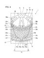
Fig. 4 is an enlarged view showing a major part ofFig. 2 . -
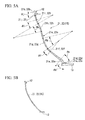
Fig. 5A is an enlarged view showing a connecting plate of the embodiment (Example 1) of a non-pneumatic tire having a tire size of 3.00-8. -
Fig. 5B is an enlarged view showing a connecting plate of Comparative Example 1 of the non-pneumatic tire having a tire size of 3.00-8. -
Fig. 6A is an enlarged view showing a connecting plate of an embodiment (Example 2) of a non-pneumatic tire having a tire size of 4.00-5. -
Fig. 6B is an enlarged view showing a connecting plate of Comparative Example 2 of the non-pneumatic tire having a tire size of 4.00-5. - Hereinafter, an embodiment of a non-pneumatic tire according to the present invention will be described with reference to the accompanying drawings.
- Further, a non-pneumatic tire 1 of the embodiment may be employed in a compact vehicle or the like that runs at a low speed, for example, electrically power scooters or the like defined by Japanese Industrial Standard JIS T 9208. In addition, in the following description, the non-pneumatic tire 1 having a tire size of, for example, 3.00-8 will be described. As shown in
Figs. 1 and2 , the non-pneumatic tire 1 of the embodiment includes anattachment body 11 attached to an axle (not shown), a ring-shaped body 13 configured to surround theattachment body 11 from the outside in a tire radial direction, a plurality of connectingmembers 15 disposed between theattachment body 11 and the ring-shaped body 13 in a tire circumferential direction and configured to connect theattachment body 11 and the ring-shaped body 13 in a relatively elastically displaceable manner, and atread member 16 disposed at an outer circumferential surface side of the ring-shaped body 13 throughout the entire circumference. - Here, the
attachment body 11, the ring-shaped body 13 and thetread member 16 are disposed on the same axis as a common axis. Hereinafter, the common axis is referred to as an axis O, a direction along the axis O is referred to as a tire width direction H, a direction perpendicular to the axis O is referred to as a tire radial direction, and a direction around the axis O is referred to as a tire circumferential direction. Further, theattachment body 11, the ring-shaped body 13 and thetread member 16 are disposed such that central sections in the tire width direction H coincide with each other. - The
attachment body 11 includes amounting rim section 17 on which a front end section of the axle is mounted, anouter ring section 18 configured to surround themounting rim section 17 from the outside in the tire radial direction, and a plurality ofribs 19 configured to connect themounting rim section 17 and theouter ring section 18. - The
mounting rim section 17, theouter ring section 18 and theribs 19 are integrally formed of a metal material such as an aluminum alloy or the like. Themounting rim section 17 and theouter ring section 18 are formed in a cylindrical shape and disposed on the same axis as the axis O. The plurality ofribs 19 are point-symmetrically disposed with respect to the axis O. - A plurality of
key groove sections 18a concaved inward in the tire radial direction and extending in the tire width direction H are formed at an outer circumferential surface of theouter ring section 18 at intervals in the tire circumferential direction. In the outer circumferential surface of theouter ring section 18, thekey groove sections 18a are opened at only first side of both ends in the tire width direction H and closed at the second side. - Further, a plurality of
hole arrays 18c, in each of which a plurality of weight-reducing holes passing in the tire radial direction are disposed at intervals in the tire width direction H, are formed at a portion of theouter ring section 18 disposed between thekey groove sections 18a which are adjacent in the tire circumferential direction at intervals in the tire circumferential direction. In addition, weight-reducingholes 19a passing in the tire width direction H are also formed in theribs 19. - In addition, in an edge of first side in the tire width direction H of the
outer ring section 18,concave sections 18b concaved toward the second side in the tire width direction H and into whichplate members 28 are fitted are formed at positions corresponding to thekey groove sections 18a. Through-holes are formed in theplate members 28, and in the wall surfaces that form theconcave sections 18b, female screw sections in communication with the through-holes of theplate members 28 fitted into theconcave sections 18b are formed in bottom wall surfaces facing the first side in the tire width direction H. Further, the plurality of female screw sections and the plurality of through-holes are formed at intervals in the tire circumferential direction. - Then, a cylindrical
exterior body 12 is fitted onto theattachment body 11. A plurality ofridge sections 12a protruding inward in the tire radial direction and extending throughout the entire length in the tire width direction H are disposed at an inner circumferential surface of theexterior body 12 at intervals in the tire circumferential direction. Theridge sections 12a are fitted into thekey groove sections 18a of theattachment body 11. - The
exterior body 12 is fixed to theattachment body 11 as theplate member 28 is fixed into theconcave section 18b in a state in which theridge section 12a is fitted into thekey groove section 18a. In this state, theridge section 12a is sandwiched between theplate member 28 and a bottom wall surface of theconcave section 18b in the tire width direction H. - Further, in wall surfaces configured to form the
key groove section 18a, a pair of side wall surfaces opposite to each other in the tire circumferential direction are perpendicular to a bottom wall surface. In addition, in outer surfaces of theridge section 12a, the pair of side wall surfaces standing upward from the inner circumferential surface of theexterior body 12 are perpendicular to a top wall surface directed inward in the tire radial direction. Further, sizes in the tire circumferential direction of theridge section 12a and thekey groove section 18a are equal to each other. - In addition, the ring-
shaped body 13 has a larger size, i.e., a larger width in the tire width direction H, than theexterior body 12, and in the example shown, the ring-shaped body 13 is formed in a cylindrical shape. - The connecting
member 15 connects an outer circumferential surface side of theattachment body 11 and an inner circumferential surface side of the ring-shaped body 13, and in the example shown, the connectingmember 15 includes a first connectingplate 21 and a second connectingplate 22, which are elastically deformable, configured to connect an outer circumferential surface of theexterior body 12 and an inner circumferential surface of the ring-shaped body 13. - In the connecting
member 15, the plurality of first connectingplates 21 are disposed in the tire circumferential direction at one position in the tire width direction H (first side in the tire width direction H), and the plurality of second connectingplates 22 are disposed in the tire circumferential direction at another position in the tire width direction H (the second side in the tire width direction H) different from the one position in the tire width direction H. That is, the plurality of first connectingplates 21 are disposed in the tire circumferential direction at the same position in the tire width direction H, and the plurality of second connectingplates 22 are disposed in the tire circumferential direction at the same position in the tire width direction H spaced apart from the first connectingplate 21 in the tire width direction H. Further, in the example shown, 60 of each of the connectingplates - Further, the plurality of connecting
members 15 are disposed between theexterior body 12 and the ring-shapedbody 13 at point-symmetrical positions with respect to the axis O. In addition, all the connectingmembers 15 have the same shape and the same size. Further, a width of the connectingmember 15 is smaller than a width of the ring-shapedbody 13. - Then, in a state in which a compressive load is not applied in the tire radial direction, the first connecting
plates 21 which are adjacent in the tire circumferential direction come out of contact with each other. Similarly, the second connectingplates 22 which are adjacent in the tire circumferential direction also come out of contact with each other in the state in which the compressive load is not applied in the tire radial direction. Further, the first connectingplates 21 and the second connectingplates 22 which are adjacent in the tire width direction H also come out of contact with each other. - Further, the widths of the first connecting
plate 21 and the second connectingplate 22 are equal to each other. - In addition, the thicknesses of the first connecting
plate 21 and the second connectingplate 22 are equal to each other. - As shown in
Figs. 2 to 4 ,first end section 21 a of the first connectingplate 21 connected to the ring-shapedbody 13 is disposed closer to first side in the tire circumferential direction than thesecond end section 21b connected to theexterior body 12, and afirst end section 22a of the second connectingplate 22 connected to the ring-shapedbody 13 is disposed closer to the second side in the tire circumferential direction than asecond end section 22b connected to theexterior body 12. - In addition, the
first end sections plate 21 and the second connectingplate 22 of the one connectingmember 15 are disposed at different positions in the tire width direction H and connected at the same position in the tire circumferential direction to the inner circumferential surface of the ring-shapedbody 13. - As shown in
Fig. 5A , in the first connectingplate 21 and the second connectingplate 22, a plurality of (in the example shown, seven)curved sections 21 d to 21 j and 22d to 22j curved in the tire circumferential direction are formed atintermediate portions first end sections second end sections plates - Specifically, the plurality of
curved sections 21d to 21 j formed at the first connectingplate 21 have the firstcurved section 21d curved to protrude toward the second side in the tire circumferential direction, the secondcurved section 21e curved to protrude toward the first side in the tire circumferential direction, the thirdcurved section 21f and the fourthcurved section 21g curved to protrude toward the second side in the tire circumferential direction, the fifthcurved section 21h curved to protrude toward the first side in the tire circumferential direction, and the sixthcurved section 21i and the seventhcurved section 21j curved to protrude toward the second side in the tire circumferential direction, which are sequentially formed in the above-described extension direction from thefirst end section 21a to thesecond end section 21b. - The plurality of
curved sections 22d to 22j formed at the second connectingplate 22 have the firstcurved section 22d curved to protrude toward the first side in the tire circumferential direction, the secondcurved section 22e curved to protrude toward the second side in the tire circumferential direction, the thirdcurved section 22f and the fourthcurved section 22g curved to protrude toward the first side in the tire circumferential direction, the fifth curved section 22h curved to protrude toward the second side in the tire circumferential direction, and the sixthcurved section 22i and the seventh curved section 22j curved to protrude toward the first side in the tire circumferential direction, which are sequentially formed in the above-described extension direction from thefirst end section 22a to thesecond end section 22b. - That is, in both of the connecting
plates curved sections 21d to 21j and 22d to 22j, curve directions of the thirdcurved sections curved sections curved sections curved sections 21 j and 22j which are adjacent in the above-described extension direction are the same direction, and curve directions of the other curved sections are opposite thereto. - In addition, in the
curved sections 21d to 21j and 22d to 22j of the connectingplates curved sections curved sections 21j and 22j disposed at both ends in the above-described extension direction (the curved sections separately joined to thefirst end sections second end sections - In the
curved sections 21d to 21j and 22d to 22j, the firstcurved sections curved sections 21j and 22j disposed at both ends in the above-described extension direction have a smaller radius of curvature in the side view of the tire than the othercurved sections 21e to 21i and 22e to 22i disposed at a central section of the extension direction. Further, in thecurved sections 21d to 21j and 22d to 22j, the firstcurved sections - Here, in the
curved sections 21d to 21j and 22d to 22j of the embodiment, as central angles θd to θj about a center of curvature increase, the thicknesses in the tire circumferential direction of the connectingplates curved sections 21d to 21j and 22d to 22j, the central angle θd of the firstcurved sections first end sections curved sections intermediate portions - In the example shown, central angles are reduced and thicknesses are reduced in sequence of the first
curved sections curved sections curved sections 21j and 22j (the central angle θj is, for example, 27.4°), the fourthcurved sections curved sections 21h and 22h (the central angle θh is, for example, 17.4°), the thirdcurved sections curved sections - Further, connecting portions between the
curved sections 21d to 21j and 22d to 22j adjacent to each other have gradually varying thicknesses, for example, from one curved section toward the other curved section adjacent to the one curved section. That is, thecurved sections 21d to 21j and 22d to 22j which are adjacent to each other are smoothly joined to each other with no step. - In addition, the thicknesses of the
curved sections 21d to 21j and 22d to 22j may be set within a range of 0.1 mm to 5.0 mm. When the thicknesses are set to 0.1 mm or more, strength of the connectingplates plates plates - Further, the lengths of both of the connecting
plates Fig. 4 , in the side view of the tire, thesecond end sections plates first end sections exterior body 12. In addition, thecurved sections 21d to 21j and 22d to 22j (seeFig. 5A ) of the first connectingplate 21 and the second connectingplate 22 protrude in directions opposed to each other in the tire circumferential direction and are the same size. - Accordingly, shapes of the connecting
members 15 in the side view of the tire are line-symmetrical with respect to an imaginary line L extending in the tire radial direction and passing thefirst end sections plates - Here, in the embodiment, the
exterior body 12, the ring-shapedbody 13 and the plurality of connectingmembers 15 are integrally formed with each other. - Further, in the embodiment, as shown in
Fig. 1 , theexterior body 12 is split into first sidesplit exterior body 25 disposed at first side in the tire width direction H and the second side splitexterior body 26 disposed at the second side in the tire width direction H. In addition, the ring-shapedbody 13 is split into first side split ring-shapedbody 23 disposed at a first side in the tire width direction H and a second side split ring-shapedbody 24 disposed at a second side in the tire width direction H. Further, in the example shown, theexterior body 12 and the ring-shapedbody 13 are split at a central section in the tire width direction H. - Then, the first side
split exterior body 25 and the first side split ring-shapedbody 23 are integrally formed with the first connectingplate 21, and the second side splitexterior body 26 and the second side split ring-shapedbody 24 are integrally formed with the second connectingplate 22. - Further, in the embodiment, the first side
split exterior body 25, the first side split ring-shapedbody 23 and the first connectingplate 21, and the second side splitexterior body 26, the second side split ring-shapedbody 24 and the second connectingplate 22 are integrally formed through casting or injection molding. - Hereinafter, a member obtained by integrally forming the first side
split exterior body 25, the first side split ring-shapedbody 23 and the first connectingplate 21 is referred to as a firstsplit case body 31, and a member obtained by integrally forming the second side splitexterior body 26, the second side split ring-shapedbody 24 and the second connectingplate 22 is referred to as a secondsplit case body 32. - Here, the injection molding may be a general method of simultaneously forming both of the entire first and second
split case bodies split case bodies split ring bodies plates - In addition, in the
split case bodies exterior bodies bodies plates - In addition, when both of the entire
split case bodies ridge section 12a formed at theexterior body 12 may be a gate portion. - In the
split case bodies plates body 13, and a central section in the tire width direction H of theexterior body 12 coincide with each other. In addition, theexterior body 12 has a smaller width than the ring-shapedbody 13, and the same width as the first connectingplate 21 and the second connectingplate 22. - Then, edges in the tire width direction H of the split ring-shaped
bodies - In addition, edges in the tire width direction H of the split
exterior bodies exterior body 12 fitted onto theattachment body 11 is prevented. - In addition, the
split case bodies Fig. 3 in a state before thebodies - Then, when the
split case bodies bodies 13 of thesplit case bodies split case bodies split case bodies members 15 are line-symmetrical to each other as described above when seen in the side view of the tire. - The
tread member 16 is formed in a cylindrical shape, integrally covers the outer circumferential surface of the ring-shapedbody 13 throughout the entire region, and in the example shown, the inner circumferential surface of thetread member 16 is closely adhered to the outer circumferential surface of the ring-shapedbody 13 throughout the entire region. Thetread member 16 is formed of, for example, natural rubber or/and vulcanized rubber in which a rubber composition is vulcanized, a thermoplastic material, or the like. For example, a thermoplastic elastomer, a thermoplastic resin, or the like is provided as the thermoplastic material. For example, an amide-based thermoplastic elastomer (TPA), an ester-based thermoplastic elastomer (TPC), an olefin-based thermoplastic elastomer (TPO), a styrene-based thermoplastic elastomer (TPS), a urethane-based thermoplastic elastomer (TPU), a thermoplastic rubber cross-linked body (TPV), or another thermoplastic elastomer (TPZ) or the like, defined by Japanese Industrial Standards JIS K6418, is provided as the thermoplastic elastomer. For example, a urethane resin, an olefin resin, a polyvinyl chloride resin, a polyamide resin, or the like, is provided as the thermoplastic resin. Further, in view of an abrasion resistance property, thetread member 16 may be formed of the vulcanized rubber. - As described above, according to the non-pneumatic tire 1 of the embodiment, in the
curved sections 21d to 21j and 22d to 22j of the one connectingplates curved sections curved sections - In particular, in the embodiment, in the connecting
plates curved sections first end sections plates curved sections intermediate portions - In addition, in the
intermediate portions plate 21 and the second connectingplate 22 of the embodiment, the curved sections (the firstcurved sections curved sections 21j and 22j) disposed at the connecting portions separately joined to thefirst end sections second end sections plate 21 and the second connectingplate 22 can be easily elastically deformed, and flexibility can be provided in the non-pneumatic tire 1 to secure good ride comfort. - Further, since the plurality of first connecting
plates 21 are disposed in the tire circumferential direction at one positions in the tire width direction H, and the plurality of second connectingplates 22 are disposed in the tire circumferential direction at other positions in the tire width direction H, interference of the connectingmembers 15 which are adjacent in the tire circumferential direction can be limited, and restriction in a disposition number can be limited. - In addition, since the connecting
members 15 are formed line-symmetrically with respect to the imaginary line L when seen in the side view of the tire, generation of a difference between a spring constant along first side in the tire circumferential direction and a spring constant along the second side in the non-pneumatic tire 1 can be limited, and good controllability can be provided. - Further, in the embodiment, since the
exterior body 12, the ring-shapedbody 13 and the plurality of connectingmembers 15 are integrally formed with each other, when the non-pneumatic tire 1 is assembled, even when both end sections of the plurality of connectingmembers 15 are not connected to theexterior body 12 and the ring-shapedbody 13, since it is sufficient if the end sections are mounted on theattachment body 11 in a state in which the ring-shapedbody 13 and the plurality of connectingmembers 15 are integrally formed with each other, manufacturing time can be reduced. - In addition, since the ring-shaped
body 13 and the plurality of connectingmembers 15 are integrally formed with each other, for example, an increase in weight can be limited in comparison with the case in which both end sections of the connectingmember 15, theexterior body 12 and the ring-shapedbody 13 are connected using a fastening member or the like. In addition, as the connecting portions of the connectingmember 15 and the ring-shapedbody 13 are integrally formed with each other, stress concentration can be attenuated in comparison with the case in which both of them are connected using the fastening member or the like. - Further, in the above-described embodiment, while the non-pneumatic tire 1 having a tire size of for example, 3.00-8 has been described, the present invention is not limited thereto but may be applied to the non-pneumatic tire 1 having various sizes. Hereinafter, the non-pneumatic tire 1 having a tire size of, for example, 4.00-5 will be described. Further, in the following description, components that are the same as those of the above-described embodiment are designated by the same reference numerals, and a description thereof will be omitted.
- As shown in
Fig. 6A , in the first connectingplate 21 and the second connectingplate 22, a plurality of (in the example shown, 8)curved sections 121d to 121k and 122d to 122k curved in the tire circumferential direction are formed at theintermediate portions first end sections second end sections plates - Specifically, the plurality of
curved sections 121d to 121k formed at the first connectingplate 21 have the firstcurved section 121d curved to protrude toward the second side in the tire circumferential direction, the second curved section 121e, the thirdcurved section 121f and the fourthcurved section 121g curved to protrude toward first side in the tire circumferential direction, the fifthcurved section 121h and the sixthcurved section 121i curved to protrude toward the second side in the tire circumferential direction, the seventhcurved section 121j curved to protrude toward first side in the tire circumferential direction, and the eighthcurved section 121k curved to protrude toward the second side in the tire circumferential direction, which are formed in sequence in the above-described extension direction from thefirst end section 21a to thesecond end section 21b. - Further, the
curved sections 122d to 122k of the second connectingplate 22 protrude in opposite directions with respect to thecurved sections 121d to 121k of the first connectingplate 21 in the tire circumferential direction and are the same size. - Like the above-described embodiment, the
curved sections 121d to 121k and 122d to 122k of the embodiment have a thickness that increases in the tire circumferential direction as the central angles θd to θk about a center of curvature thereof increase. Specifically, in thecurved sections 121d to 121k and 122d to 122k, a configuration in which the central angle θd of the firstcurved sections first end sections curved sections 121e and 122e disposed at theintermediate portions - Central angles are reduced and thicknesses of the
curved sections 121d to 121k and 122d to 122k are reduced in sequence of in the example shown, the firstcurved sections curved sections curved sections curved sections curved sections curved sections curved sections curved sections - Here, the inventor(s) performed verification tests to compare weights and strengths in Examples 1 and 2 and Comparative Examples 1 and 2 having two kinds of different tire sizes.
- In the tests, the non-pneumatic tire shown in
Fig. 5A was employed as Example 1, and the non-pneumatic tire 1 shown inFig. 6A was employed as Example 2. In addition, as Comparative Examples 1 and 2 corresponding to Examples 1 and 2, respectively, as shown inFigs. 5B and6B , in the non-pneumatic tire having the same size as the corresponding Examples 1 and 2, a configuration in which the thickness in the tire circumferential direction of the connectingplates plates plates plates Figs. 5B and6B , portions corresponding to Examples 1 and 2 are designated by the same reference numerals. - The results of the tests under the above-described conditions showed that the non-pneumatic tire of each of Examples can secure sufficient strength with the tire size while attempting a decrease in weight in comparison with the non-pneumatic tire of each of Comparative Examples. Specifically, if the weight and strength of Comparative Example 1 are both set at 100, it was confirmed that, in Example 1, the weight was 90 and the strength was 210. In addition, if the weight and strength of Comparative Example 2 are both set at 100, it was confirmed that, in Example 2, the weight was 93 and the strength was 135.
- This is considered to be due to the fact that, in the curved sections, the thickness of a portion having a large central angle, in which bending deformation is largely generated to cause easy application of a load, is increased to secure strength, while the thickness of a portion having a small central angle, in which bending deformation cannot be easily generated to cause difficulty in application of the load, is reduced to suppress an increase in weight.
- Further, the technical spirit of the present invention is not limited to the embodiments but various modifications may be made without departing from the spirit of the present invention.
- For example, the curve direction of the curved section in the first connecting
plate 21 and the curve direction of the curved section in the second connectingplate 22 may be appropriately varied without being limited to the above-described embodiments. - Further, in the above-described embodiments, while the case in which, in the curved sections, for example, the first
curved sections first end sections curved sections intermediate portions - In addition, in the above-described embodiments, while a configuration in which the first connecting
plate 21 and the second connectingplate 22 are disposed in two rows in the tire width direction H as the connectingmember 15 has been described, the present invention is not limited thereto but the connectingmembers 15 may be disposed in a plurality of rows, in three rows or more, or in one row in the tire width direction H. - In addition, the plurality of connecting
members 15 may be installed between theexterior body 12 and the ring-shapedbody 13 in the tire width direction H. - In addition, instead of the above-described embodiments, for example, the
second end sections plate 21 and the second connectingplate 22 may be connected at opposite positions with the axis O sandwiched therebetween on the outer circumferential surface of theexterior body 12 in the tire radial direction, or may be connected to thefirst end sections plate 21 and the second connectingplate 22 at opposite positions in the tire radial direction on the outer circumferential surface of theexterior body 12. - In addition, instead of the above-described embodiments, the
first end sections plates body 13. - Further, a gap in the tire width direction H may be formed between the first side
split exterior body 25 and the second side splitexterior body 26. - In addition, the
exterior body 12 and the ring-shapedbody 13 may be split into three or more parts in the tire width direction H, or may not be split. - Further, the first and second
split case bodies - In addition, in the above-described embodiments, while the
exterior body 12, the ring-shapedbody 13 and the plurality of connectingmembers 15 are integrally formed with each other, the present invention is not limited thereto but the components may be connected to each other after being separately formed. Further, theexterior body 12 may be integrally formed with theattachment body 11. - In addition, in the above-described embodiments, while the configuration in which the
first end sections members 15 are indirectly connected to theattachment body 11 via theexterior body 12 has been described, the present invention is not limited thereto but thefirst end sections members 15 may be directly connected to theattachment body 11. - In addition, the components of the above-described embodiments may be appropriately substituted with known components without departing from the spirit of the present invention, or the above-described variants may be appropriately combined.
- The non-pneumatic tire of the present invention can secure sufficient strength while limiting an increase in weight.
-
- 1 non-pneumatic tire
- 11 attachment body
- 12 exterior body
- 13 ring-shaped body
- 15 connecting member
- 21 first connecting plate
- 22 second connecting plate
- 21 a, 22a first end section
- 21b, 22b second end section
- 21d to 21j, 22d to 22j, 121d to 121k, 122d to 122k curved section
- H tire width direction
- L imaginary line
- O taxis
Claims (8)
- A non-pneumatic tire comprising:an attachment body attached to an axle;a ring-shaped body configured to surround the attachment body from the outside in a tire radial direction; anda plurality of connecting members disposed between the attachment body and the ring-shaped body in a tire circumferential direction and configured to displaceably connect the attachment body and the ring-shaped body,wherein the connecting member comprises a connecting plate configured to connect the attachment body and the ring-shaped body,a plurality of curved sections curved in the tire circumferential direction are formed at the connecting plate in a direction in which the connecting plate extends in a side view of the tire when the tire is seen from the tire width direction, andin the plurality of curved sections of the one connecting plate, a thickness of a maximum curved section in which a central angle about a center of curvature of each of the curved sections is largest is maximized, and a thickness of a minimum curved section in which the central angle is smallest is minimized.
- The non-pneumatic tire according to claim 1, wherein the maximum curved section is joined to first end section connected to the ring-shaped body in the connecting plate, and
the minimum curved section is disposed at an intermediate portion disposed between the second end section connected to the attachment body and the first end section of the connecting plate. - The non-pneumatic tire according to claim 1, wherein the connecting member comprises a first connecting plate and a second connecting plate configured to connect the attachment body and the ring-shaped body,
first end section of the first connecting plate connected to the ring-shaped body is disposed closer to first side in the tire circumferential direction than the second end section connected to the attachment body,
first end section of the second connecting plate connected to the ring-shaped body is disposed closer to the second side in the tire circumferential direction than the second end section connected to the attachment body,
in an intermediate portion disposed between the first end section and the second end section of the first connecting plate, curved sections separately joined to the first end section and the second end section are formed to protrude toward the second side in the tire circumferential direction, and
in an intermediate portion disposed between the first end section and the second end section of the second connecting plate, curved sections separately joined to the first end section and the second end section are formed to protrude toward first side in the tire circumferential direction. - The non-pneumatic tire according to claim 1, comprising a cylindrical exterior body fitted onto the attachment body,
wherein the exterior body is integrally formed with the ring-shaped body and the plurality of connecting members. - The non-pneumatic tire according to claim 2, wherein the connecting member comprises a first connecting plate and a second connecting plate configured to connect the attachment body and the ring-shaped body,
first end section of the first connecting plate connected to the ring-shaped body is disposed closer to first side in the tire circumferential direction than the second end section connected to the attachment body,
first end section of the second connecting plate connected to the ring-shaped body is disposed closer to the second side in the tire circumferential direction than the second end section connected to the attachment body,
in an intermediate portion disposed between the first end section and the second end section of the first connecting plate, curved sections separately joined to the first end section and the second end section are formed to protrude toward the second side in the tire circumferential direction, and
in an intermediate portion disposed between the first end section and the second end section of the second connecting plate, curved sections separately joined to the first end section and the second end section are formed to protrude toward first side in the tire circumferential direction. - The non-pneumatic tire according to claim 2, comprising a cylindrical exterior body fitted onto the attachment body,
wherein the exterior body is integrally formed with the ring-shaped body and the plurality of connecting members. - The non-pneumatic tire according to claim 3, comprising a cylindrical exterior body fitted onto the attachment body,
wherein the exterior body is integrally formed with the ring-shaped body and the plurality of connecting members. - The non-pneumatic tire according to claim 5, comprising a cylindrical exterior body fitted onto the attachment body,
wherein the exterior body is integrally formed with the ring-shaped body and the plurality of connecting members.
Applications Claiming Priority (2)
| Application Number | Priority Date | Filing Date | Title |
|---|---|---|---|
| JP2012240523A JP5930941B2 (en) | 2012-10-31 | 2012-10-31 | Non pneumatic tire |
| PCT/JP2013/079550 WO2014069570A1 (en) | 2012-10-31 | 2013-10-31 | Non-pneumatic tire |
Publications (3)
| Publication Number | Publication Date |
|---|---|
| EP2915681A1 true EP2915681A1 (en) | 2015-09-09 |
| EP2915681A4 EP2915681A4 (en) | 2016-06-22 |
| EP2915681B1 EP2915681B1 (en) | 2019-05-01 |
Family
ID=50627468
Family Applications (1)
| Application Number | Title | Priority Date | Filing Date |
|---|---|---|---|
| EP13851636.4A Not-in-force EP2915681B1 (en) | 2012-10-31 | 2013-10-31 | Non-pneumatic tire |
Country Status (5)
| Country | Link |
|---|---|
| US (1) | US9550393B2 (en) |
| EP (1) | EP2915681B1 (en) |
| JP (1) | JP5930941B2 (en) |
| CN (1) | CN104768772B (en) |
| WO (1) | WO2014069570A1 (en) |
Cited By (5)
| Publication number | Priority date | Publication date | Assignee | Title |
|---|---|---|---|---|
| EP3069897A4 (en) * | 2013-11-15 | 2016-11-23 | Bridgestone Corp | NON-PNEUMATIC TIRE |
| EP2902217B1 (en) * | 2012-11-05 | 2019-06-12 | Bridgestone Corporation | Non-pneumatic tire |
| EP3507105A4 (en) * | 2016-09-02 | 2020-04-08 | Razor USA LLC | Airless tire |
| EP3888937A4 (en) * | 2018-11-30 | 2022-08-03 | Bridgestone Corporation | NON-PNEUMATIC TIRE |
| USD1035558S1 (en) | 2016-09-02 | 2024-07-16 | Razor Usa Llc | Airless tire |
Families Citing this family (27)
| Publication number | Priority date | Publication date | Assignee | Title |
|---|---|---|---|---|
| JP5879089B2 (en) * | 2011-10-20 | 2016-03-08 | 株式会社ブリヂストン | Non-pneumatic tire manufacturing method |
| JP6242015B2 (en) * | 2012-12-26 | 2017-12-06 | 株式会社ブリヂストン | Non pneumatic tire |
| JP6051037B2 (en) * | 2012-12-26 | 2016-12-21 | 株式会社ブリヂストン | Non pneumatic tire |
| EP3007909A4 (en) | 2013-06-15 | 2017-03-01 | Ronald Thompson | Annular ring and non-pneumatic tire |
| JP6358733B2 (en) * | 2013-10-10 | 2018-07-18 | 株式会社ブリヂストン | Non pneumatic tire |
| EP3069898B1 (en) * | 2013-11-15 | 2018-05-16 | Bridgestone Corporation | Non-pneumatic tire |
| US20170305195A1 (en) * | 2014-11-28 | 2017-10-26 | Bridgestone Corporation | Non-pneumatic tire |
| JP6522931B2 (en) * | 2014-11-28 | 2019-05-29 | 株式会社ブリヂストン | Non pneumatic tire |
| JP6522936B2 (en) * | 2014-12-02 | 2019-05-29 | 株式会社ブリヂストン | Non pneumatic tire |
| EP3253591B1 (en) | 2015-02-04 | 2021-06-30 | Camso Inc. | Non-pneumatic tire and other annular devices |
| CN108136835B (en) * | 2015-10-09 | 2019-11-22 | 株式会社普利司通 | Non-pneumatic tires |
| JP6610161B2 (en) * | 2015-10-22 | 2019-11-27 | 住友ゴム工業株式会社 | Airless tire |
| WO2017072562A1 (en) * | 2015-10-30 | 2017-05-04 | Compagnie Generale Des Etablissements Michelin | Spoke fabrication for a non-pneumatic wheel |
| US11999419B2 (en) | 2015-12-16 | 2024-06-04 | Camso Inc. | Track system for traction of a vehicle |
| CN105730149B (en) * | 2016-02-19 | 2017-09-29 | 齐克岐 | A kind of bended plate type tire |
| KR101789407B1 (en) * | 2016-02-26 | 2017-10-23 | 엘지전자 주식회사 | Robot cleaner and wheel assembly |
| EP3638515B1 (en) | 2017-06-15 | 2023-04-05 | Camso Inc. | Wheel comprising a non-pneumatic tire |
| JP7004562B2 (en) * | 2017-12-14 | 2022-02-10 | Toyo Tire株式会社 | Non-pneumatic tires |
| WO2019118225A1 (en) | 2017-12-14 | 2019-06-20 | Bridgestone Americas Tire Operations, Llc | Non-pneumatic tire with multi-piece web |
| USD1009724S1 (en) | 2018-08-23 | 2024-01-02 | Jelly Products Limited | Wheel side |
| JP7123771B2 (en) * | 2018-11-30 | 2022-08-23 | 株式会社ブリヂストン | non-pneumatic tire |
| JP1654471S (en) * | 2019-05-23 | 2020-03-09 | ||
| CN111319398A (en) * | 2020-02-28 | 2020-06-23 | 季华实验室 | Support body, elastic support assembly, non-pneumatic tire and method of manufacturing the same |
| GB2587476B (en) * | 2020-07-03 | 2021-09-15 | Sam Pearce Design Ltd | A wheel |
| JP7615746B2 (en) * | 2021-02-18 | 2025-01-17 | 住友ゴム工業株式会社 | Airless tires |
| CA3220051A1 (en) * | 2021-08-17 | 2023-02-23 | Richard Krulik | Shock absorbing luggage wheel |
| IT202300007008A1 (en) * | 2023-04-12 | 2024-10-12 | Stiga S P A In Breve Anche St S P A | Cladding, frame, assembly comprising the cladding and the frame and device comprising the assembly |
Family Cites Families (22)
| Publication number | Priority date | Publication date | Assignee | Title |
|---|---|---|---|---|
| US94839A (en) * | 1869-09-14 | Improved carriage-wheel | ||
| US1039311A (en) | 1911-12-07 | 1912-09-24 | C A Benbow | Spring-wheel. |
| US1055447A (en) | 1911-12-28 | 1913-03-11 | Charley J Craig | Resilient wheel. |
| GB117698A (en) | 1917-08-07 | 1918-08-01 | Arthur Woosnam | Improvements in Resilient Wheels. |
| US1591982A (en) | 1925-03-18 | 1926-07-13 | William R Kirkwood | Demountable cushion tire |
| US1828322A (en) * | 1929-08-09 | 1931-10-20 | William E Kawalle | Spring wheel |
| GB1292928A (en) | 1970-04-17 | 1972-10-18 | John Dudley Wells Gregg | Improvements relating to spring wheels for vehicles |
| GB2042674B (en) | 1979-02-19 | 1983-02-16 | British Gas Corp | Friction drive wheel |
| DE3175652D1 (en) | 1980-11-10 | 1987-01-15 | Wheel Dev Ltd | Wheel with resilient spokes |
| US6615885B1 (en) * | 2000-10-31 | 2003-09-09 | Irobot Corporation | Resilient wheel structure |
| JP2006151002A (en) | 2004-11-25 | 2006-06-15 | Daiwarashi Co Ltd | Caster base body, caster, and manufacturing method for caster base body |
| US7523773B2 (en) * | 2005-10-21 | 2009-04-28 | The Boeing Company | Non-pneumatic wheel |
| SE530394C2 (en) * | 2006-10-04 | 2008-05-20 | Sesyk Ab | Shock absorbing wheels |
| WO2010012091A1 (en) * | 2008-08-01 | 2010-02-04 | Mindmatter Innovates Inc. | Reactive planar suspension for a wheel |
| NL2002956C2 (en) * | 2009-06-03 | 2010-12-07 | Vredestein Banden B V | Non-pneumatic tire. |
| JP5624737B2 (en) | 2009-07-22 | 2014-11-12 | 株式会社ブリヂストン | Non pneumatic tire |
| JP5622400B2 (en) * | 2010-01-29 | 2014-11-12 | 株式会社ブリヂストン | Non pneumatic tire |
| JP5405431B2 (en) * | 2010-10-25 | 2014-02-05 | 彦司 山本 | Traveling wheel |
| CN201931931U (en) | 2010-12-28 | 2011-08-17 | 李德贵 | Novel spring shockproof automobile wheel |
| JP5879089B2 (en) | 2011-10-20 | 2016-03-08 | 株式会社ブリヂストン | Non-pneumatic tire manufacturing method |
| WO2013152067A1 (en) | 2012-04-05 | 2013-10-10 | Compagnie Generale Des Establissements Michelin | Spoke for a tire with optimized thickness for improved durability |
| TW201538375A (en) * | 2014-04-03 | 2015-10-16 | Hons Ind Co Ltd | Buffer type gear member |
-
2012
- 2012-10-31 JP JP2012240523A patent/JP5930941B2/en not_active Expired - Fee Related
-
2013
- 2013-10-31 EP EP13851636.4A patent/EP2915681B1/en not_active Not-in-force
- 2013-10-31 WO PCT/JP2013/079550 patent/WO2014069570A1/en not_active Ceased
- 2013-10-31 CN CN201380056093.3A patent/CN104768772B/en not_active Expired - Fee Related
- 2013-10-31 US US14/438,490 patent/US9550393B2/en not_active Expired - Fee Related
Cited By (7)
| Publication number | Priority date | Publication date | Assignee | Title |
|---|---|---|---|---|
| EP2902217B1 (en) * | 2012-11-05 | 2019-06-12 | Bridgestone Corporation | Non-pneumatic tire |
| EP3069897A4 (en) * | 2013-11-15 | 2016-11-23 | Bridgestone Corp | NON-PNEUMATIC TIRE |
| US10576786B2 (en) | 2013-11-15 | 2020-03-03 | Bridgestone Corporation | Non-pneumatic tire |
| EP3507105A4 (en) * | 2016-09-02 | 2020-04-08 | Razor USA LLC | Airless tire |
| USD1035558S1 (en) | 2016-09-02 | 2024-07-16 | Razor Usa Llc | Airless tire |
| USD1115661S1 (en) | 2016-09-02 | 2026-03-03 | Razor Usa Llc | Airless tire |
| EP3888937A4 (en) * | 2018-11-30 | 2022-08-03 | Bridgestone Corporation | NON-PNEUMATIC TIRE |
Also Published As
| Publication number | Publication date |
|---|---|
| WO2014069570A1 (en) | 2014-05-08 |
| US9550393B2 (en) | 2017-01-24 |
| CN104768772B (en) | 2017-03-29 |
| JP5930941B2 (en) | 2016-06-08 |
| EP2915681A4 (en) | 2016-06-22 |
| CN104768772A (en) | 2015-07-08 |
| EP2915681B1 (en) | 2019-05-01 |
| JP2014088144A (en) | 2014-05-15 |
| US20150283851A1 (en) | 2015-10-08 |
Similar Documents
| Publication | Publication Date | Title |
|---|---|---|
| EP2915681B1 (en) | Non-pneumatic tire | |
| EP2902217B1 (en) | Non-pneumatic tire | |
| US9511625B2 (en) | Non-pneumatic tire | |
| EP2910387B1 (en) | Non-pneumatic tire | |
| EP2939850B1 (en) | Non-pneumatic tyre | |
| EP2889158B1 (en) | Non-pneumatic tire | |
| EP2896510B1 (en) | Non-pneumatic tyre | |
| EP2886368B1 (en) | Non-pneumatic tyre | |
| EP3069897B1 (en) | Non-pneumatic tire | |
| EP3069898A1 (en) | Non-pneumatic tire | |
| EP2939851B1 (en) | Non-pneumatic tyre | |
| JP5894964B2 (en) | Non pneumatic tire | |
| JP5851450B2 (en) | Non pneumatic tire | |
| JP5879184B2 (en) | Mounting body and non-pneumatic tire |
Legal Events
| Date | Code | Title | Description |
|---|---|---|---|
| PUAI | Public reference made under article 153(3) epc to a published international application that has entered the european phase |
Free format text: ORIGINAL CODE: 0009012 |
|
| 17P | Request for examination filed |
Effective date: 20150428 |
|
| AK | Designated contracting states |
Kind code of ref document: A1 Designated state(s): AL AT BE BG CH CY CZ DE DK EE ES FI FR GB GR HR HU IE IS IT LI LT LU LV MC MK MT NL NO PL PT RO RS SE SI SK SM TR |
|
| AX | Request for extension of the european patent |
Extension state: BA ME |
|
| DAX | Request for extension of the european patent (deleted) | ||
| RA4 | Supplementary search report drawn up and despatched (corrected) |
Effective date: 20160520 |
|
| RIC1 | Information provided on ipc code assigned before grant |
Ipc: B60C 7/18 20060101ALI20160513BHEP Ipc: B60B 9/26 20060101ALI20160513BHEP Ipc: B60B 9/04 20060101AFI20160513BHEP |
|
| STAA | Information on the status of an ep patent application or granted ep patent |
Free format text: STATUS: EXAMINATION IS IN PROGRESS |
|
| 17Q | First examination report despatched |
Effective date: 20171220 |
|
| GRAP | Despatch of communication of intention to grant a patent |
Free format text: ORIGINAL CODE: EPIDOSNIGR1 |
|
| STAA | Information on the status of an ep patent application or granted ep patent |
Free format text: STATUS: GRANT OF PATENT IS INTENDED |
|
| INTG | Intention to grant announced |
Effective date: 20181031 |
|
| GRAS | Grant fee paid |
Free format text: ORIGINAL CODE: EPIDOSNIGR3 |
|
| GRAA | (expected) grant |
Free format text: ORIGINAL CODE: 0009210 |
|
| STAA | Information on the status of an ep patent application or granted ep patent |
Free format text: STATUS: THE PATENT HAS BEEN GRANTED |
|
| AK | Designated contracting states |
Kind code of ref document: B1 Designated state(s): AL AT BE BG CH CY CZ DE DK EE ES FI FR GB GR HR HU IE IS IT LI LT LU LV MC MK MT NL NO PL PT RO RS SE SI SK SM TR |
|
| REG | Reference to a national code |
Ref country code: GB Ref legal event code: FG4D |
|
| REG | Reference to a national code |
Ref country code: CH Ref legal event code: EP Ref country code: AT Ref legal event code: REF Ref document number: 1126414 Country of ref document: AT Kind code of ref document: T Effective date: 20190515 |
|
| REG | Reference to a national code |
Ref country code: DE Ref legal event code: R096 Ref document number: 602013054804 Country of ref document: DE |
|
| REG | Reference to a national code |
Ref country code: IE Ref legal event code: FG4D |
|
| REG | Reference to a national code |
Ref country code: NL Ref legal event code: MP Effective date: 20190501 |
|
| REG | Reference to a national code |
Ref country code: LT Ref legal event code: MG4D |
|
| PG25 | Lapsed in a contracting state [announced via postgrant information from national office to epo] |
Ref country code: NO Free format text: LAPSE BECAUSE OF FAILURE TO SUBMIT A TRANSLATION OF THE DESCRIPTION OR TO PAY THE FEE WITHIN THE PRESCRIBED TIME-LIMIT Effective date: 20190801 Ref country code: LT Free format text: LAPSE BECAUSE OF FAILURE TO SUBMIT A TRANSLATION OF THE DESCRIPTION OR TO PAY THE FEE WITHIN THE PRESCRIBED TIME-LIMIT Effective date: 20190501 Ref country code: ES Free format text: LAPSE BECAUSE OF FAILURE TO SUBMIT A TRANSLATION OF THE DESCRIPTION OR TO PAY THE FEE WITHIN THE PRESCRIBED TIME-LIMIT Effective date: 20190501 Ref country code: NL Free format text: LAPSE BECAUSE OF FAILURE TO SUBMIT A TRANSLATION OF THE DESCRIPTION OR TO PAY THE FEE WITHIN THE PRESCRIBED TIME-LIMIT Effective date: 20190501 Ref country code: SE Free format text: LAPSE BECAUSE OF FAILURE TO SUBMIT A TRANSLATION OF THE DESCRIPTION OR TO PAY THE FEE WITHIN THE PRESCRIBED TIME-LIMIT Effective date: 20190501 Ref country code: HR Free format text: LAPSE BECAUSE OF FAILURE TO SUBMIT A TRANSLATION OF THE DESCRIPTION OR TO PAY THE FEE WITHIN THE PRESCRIBED TIME-LIMIT Effective date: 20190501 Ref country code: AL Free format text: LAPSE BECAUSE OF FAILURE TO SUBMIT A TRANSLATION OF THE DESCRIPTION OR TO PAY THE FEE WITHIN THE PRESCRIBED TIME-LIMIT Effective date: 20190501 Ref country code: PT Free format text: LAPSE BECAUSE OF FAILURE TO SUBMIT A TRANSLATION OF THE DESCRIPTION OR TO PAY THE FEE WITHIN THE PRESCRIBED TIME-LIMIT Effective date: 20190901 Ref country code: FI Free format text: LAPSE BECAUSE OF FAILURE TO SUBMIT A TRANSLATION OF THE DESCRIPTION OR TO PAY THE FEE WITHIN THE PRESCRIBED TIME-LIMIT Effective date: 20190501 |
|
| PG25 | Lapsed in a contracting state [announced via postgrant information from national office to epo] |
Ref country code: RS Free format text: LAPSE BECAUSE OF FAILURE TO SUBMIT A TRANSLATION OF THE DESCRIPTION OR TO PAY THE FEE WITHIN THE PRESCRIBED TIME-LIMIT Effective date: 20190501 Ref country code: LV Free format text: LAPSE BECAUSE OF FAILURE TO SUBMIT A TRANSLATION OF THE DESCRIPTION OR TO PAY THE FEE WITHIN THE PRESCRIBED TIME-LIMIT Effective date: 20190501 Ref country code: GR Free format text: LAPSE BECAUSE OF FAILURE TO SUBMIT A TRANSLATION OF THE DESCRIPTION OR TO PAY THE FEE WITHIN THE PRESCRIBED TIME-LIMIT Effective date: 20190802 Ref country code: BG Free format text: LAPSE BECAUSE OF FAILURE TO SUBMIT A TRANSLATION OF THE DESCRIPTION OR TO PAY THE FEE WITHIN THE PRESCRIBED TIME-LIMIT Effective date: 20190801 |
|
| REG | Reference to a national code |
Ref country code: AT Ref legal event code: MK05 Ref document number: 1126414 Country of ref document: AT Kind code of ref document: T Effective date: 20190501 |
|
| PG25 | Lapsed in a contracting state [announced via postgrant information from national office to epo] |
Ref country code: IS Free format text: LAPSE BECAUSE OF FAILURE TO SUBMIT A TRANSLATION OF THE DESCRIPTION OR TO PAY THE FEE WITHIN THE PRESCRIBED TIME-LIMIT Effective date: 20190901 |
|
| PG25 | Lapsed in a contracting state [announced via postgrant information from national office to epo] |
Ref country code: RO Free format text: LAPSE BECAUSE OF FAILURE TO SUBMIT A TRANSLATION OF THE DESCRIPTION OR TO PAY THE FEE WITHIN THE PRESCRIBED TIME-LIMIT Effective date: 20190501 Ref country code: CZ Free format text: LAPSE BECAUSE OF FAILURE TO SUBMIT A TRANSLATION OF THE DESCRIPTION OR TO PAY THE FEE WITHIN THE PRESCRIBED TIME-LIMIT Effective date: 20190501 Ref country code: SK Free format text: LAPSE BECAUSE OF FAILURE TO SUBMIT A TRANSLATION OF THE DESCRIPTION OR TO PAY THE FEE WITHIN THE PRESCRIBED TIME-LIMIT Effective date: 20190501 Ref country code: DK Free format text: LAPSE BECAUSE OF FAILURE TO SUBMIT A TRANSLATION OF THE DESCRIPTION OR TO PAY THE FEE WITHIN THE PRESCRIBED TIME-LIMIT Effective date: 20190501 Ref country code: EE Free format text: LAPSE BECAUSE OF FAILURE TO SUBMIT A TRANSLATION OF THE DESCRIPTION OR TO PAY THE FEE WITHIN THE PRESCRIBED TIME-LIMIT Effective date: 20190501 Ref country code: AT Free format text: LAPSE BECAUSE OF FAILURE TO SUBMIT A TRANSLATION OF THE DESCRIPTION OR TO PAY THE FEE WITHIN THE PRESCRIBED TIME-LIMIT Effective date: 20190501 |
|
| REG | Reference to a national code |
Ref country code: DE Ref legal event code: R097 Ref document number: 602013054804 Country of ref document: DE |
|
| PG25 | Lapsed in a contracting state [announced via postgrant information from national office to epo] |
Ref country code: IT Free format text: LAPSE BECAUSE OF FAILURE TO SUBMIT A TRANSLATION OF THE DESCRIPTION OR TO PAY THE FEE WITHIN THE PRESCRIBED TIME-LIMIT Effective date: 20190501 Ref country code: SM Free format text: LAPSE BECAUSE OF FAILURE TO SUBMIT A TRANSLATION OF THE DESCRIPTION OR TO PAY THE FEE WITHIN THE PRESCRIBED TIME-LIMIT Effective date: 20190501 |
|
| PLBE | No opposition filed within time limit |
Free format text: ORIGINAL CODE: 0009261 |
|
| STAA | Information on the status of an ep patent application or granted ep patent |
Free format text: STATUS: NO OPPOSITION FILED WITHIN TIME LIMIT |
|
| PG25 | Lapsed in a contracting state [announced via postgrant information from national office to epo] |
Ref country code: TR Free format text: LAPSE BECAUSE OF FAILURE TO SUBMIT A TRANSLATION OF THE DESCRIPTION OR TO PAY THE FEE WITHIN THE PRESCRIBED TIME-LIMIT Effective date: 20190501 |
|
| 26N | No opposition filed |
Effective date: 20200204 |
|
| PG25 | Lapsed in a contracting state [announced via postgrant information from national office to epo] |
Ref country code: PL Free format text: LAPSE BECAUSE OF FAILURE TO SUBMIT A TRANSLATION OF THE DESCRIPTION OR TO PAY THE FEE WITHIN THE PRESCRIBED TIME-LIMIT Effective date: 20190501 |
|
| PG25 | Lapsed in a contracting state [announced via postgrant information from national office to epo] |
Ref country code: SI Free format text: LAPSE BECAUSE OF FAILURE TO SUBMIT A TRANSLATION OF THE DESCRIPTION OR TO PAY THE FEE WITHIN THE PRESCRIBED TIME-LIMIT Effective date: 20190501 Ref country code: MC Free format text: LAPSE BECAUSE OF FAILURE TO SUBMIT A TRANSLATION OF THE DESCRIPTION OR TO PAY THE FEE WITHIN THE PRESCRIBED TIME-LIMIT Effective date: 20190501 |
|
| REG | Reference to a national code |
Ref country code: CH Ref legal event code: PL |
|
| PG25 | Lapsed in a contracting state [announced via postgrant information from national office to epo] |
Ref country code: LI Free format text: LAPSE BECAUSE OF NON-PAYMENT OF DUE FEES Effective date: 20191031 Ref country code: CH Free format text: LAPSE BECAUSE OF NON-PAYMENT OF DUE FEES Effective date: 20191031 Ref country code: LU Free format text: LAPSE BECAUSE OF NON-PAYMENT OF DUE FEES Effective date: 20191031 |
|
| REG | Reference to a national code |
Ref country code: BE Ref legal event code: MM Effective date: 20191031 |
|
| PG25 | Lapsed in a contracting state [announced via postgrant information from national office to epo] |
Ref country code: BE Free format text: LAPSE BECAUSE OF NON-PAYMENT OF DUE FEES Effective date: 20191031 |
|
| GBPC | Gb: european patent ceased through non-payment of renewal fee |
Effective date: 20191031 |
|
| PG25 | Lapsed in a contracting state [announced via postgrant information from national office to epo] |
Ref country code: IE Free format text: LAPSE BECAUSE OF NON-PAYMENT OF DUE FEES Effective date: 20191031 Ref country code: GB Free format text: LAPSE BECAUSE OF NON-PAYMENT OF DUE FEES Effective date: 20191031 |
|
| PG25 | Lapsed in a contracting state [announced via postgrant information from national office to epo] |
Ref country code: CY Free format text: LAPSE BECAUSE OF FAILURE TO SUBMIT A TRANSLATION OF THE DESCRIPTION OR TO PAY THE FEE WITHIN THE PRESCRIBED TIME-LIMIT Effective date: 20190501 |
|
| PG25 | Lapsed in a contracting state [announced via postgrant information from national office to epo] |
Ref country code: HU Free format text: LAPSE BECAUSE OF FAILURE TO SUBMIT A TRANSLATION OF THE DESCRIPTION OR TO PAY THE FEE WITHIN THE PRESCRIBED TIME-LIMIT; INVALID AB INITIO Effective date: 20131031 Ref country code: MT Free format text: LAPSE BECAUSE OF FAILURE TO SUBMIT A TRANSLATION OF THE DESCRIPTION OR TO PAY THE FEE WITHIN THE PRESCRIBED TIME-LIMIT Effective date: 20190501 |
|
| PG25 | Lapsed in a contracting state [announced via postgrant information from national office to epo] |
Ref country code: MK Free format text: LAPSE BECAUSE OF FAILURE TO SUBMIT A TRANSLATION OF THE DESCRIPTION OR TO PAY THE FEE WITHIN THE PRESCRIBED TIME-LIMIT Effective date: 20190501 |
|
| P01 | Opt-out of the competence of the unified patent court (upc) registered |
Effective date: 20230531 |
|
| PGFP | Annual fee paid to national office [announced via postgrant information from national office to epo] |
Ref country code: FR Payment date: 20231026 Year of fee payment: 11 Ref country code: DE Payment date: 20231020 Year of fee payment: 11 |
|
| REG | Reference to a national code |
Ref country code: DE Ref legal event code: R119 Ref document number: 602013054804 Country of ref document: DE |
|
| PG25 | Lapsed in a contracting state [announced via postgrant information from national office to epo] |
Ref country code: DE Free format text: LAPSE BECAUSE OF NON-PAYMENT OF DUE FEES Effective date: 20250501 |
|
| PG25 | Lapsed in a contracting state [announced via postgrant information from national office to epo] |
Ref country code: FR Free format text: LAPSE BECAUSE OF NON-PAYMENT OF DUE FEES Effective date: 20241031 |