EP2914103B1 - Tierfalle - Google Patents
Tierfalle Download PDFInfo
- Publication number
- EP2914103B1 EP2914103B1 EP13792057.5A EP13792057A EP2914103B1 EP 2914103 B1 EP2914103 B1 EP 2914103B1 EP 13792057 A EP13792057 A EP 13792057A EP 2914103 B1 EP2914103 B1 EP 2914103B1
- Authority
- EP
- European Patent Office
- Prior art keywords
- support
- housing
- trap
- trigger
- animal
- Prior art date
- Legal status (The legal status is an assumption and is not a legal conclusion. Google has not performed a legal analysis and makes no representation as to the accuracy of the status listed.)
- Active
Links
Images

Classifications
-
- A—HUMAN NECESSITIES
- A01—AGRICULTURE; FORESTRY; ANIMAL HUSBANDRY; HUNTING; TRAPPING; FISHING
- A01M—CATCHING, TRAPPING OR SCARING OF ANIMALS; APPARATUS FOR THE DESTRUCTION OF NOXIOUS ANIMALS OR NOXIOUS PLANTS
- A01M23/00—Traps for animals
- A01M23/24—Spring traps, e.g. jaw or like spring traps
- A01M23/30—Break-back traps, i.e. mouse-trap type
-
- A—HUMAN NECESSITIES
- A01—AGRICULTURE; FORESTRY; ANIMAL HUSBANDRY; HUNTING; TRAPPING; FISHING
- A01M—CATCHING, TRAPPING OR SCARING OF ANIMALS; APPARATUS FOR THE DESTRUCTION OF NOXIOUS ANIMALS OR NOXIOUS PLANTS
- A01M23/00—Traps for animals
- A01M23/24—Spring traps, e.g. jaw or like spring traps
-
- A—HUMAN NECESSITIES
- A01—AGRICULTURE; FORESTRY; ANIMAL HUSBANDRY; HUNTING; TRAPPING; FISHING
- A01M—CATCHING, TRAPPING OR SCARING OF ANIMALS; APPARATUS FOR THE DESTRUCTION OF NOXIOUS ANIMALS OR NOXIOUS PLANTS
- A01M23/00—Traps for animals
- A01M23/24—Spring traps, e.g. jaw or like spring traps
- A01M23/34—Spring traps, e.g. jaw or like spring traps with snares
Definitions
- the present invention relates to an animal trap.
- European patent 1894469 describes an animal trap which has a generally cylindrical housing which is arranged to be deployed in a substantially vertical position. Movable within the cylindrical housing is a closing part which is held against spring pressure in an upper position. When an animal pushes against a pivotable trigger mechanism extending in an opening at the base of the trap, the trap is triggered and the closing part is propelled downwardly where it can exert a lethal closing force on an animal in the opening.
- This known trap has a number of disadvantages.
- the trigger mechanism hangs on surfaces of the closing part and there can be difficulties in setting the trap unless it is arranged accurately vertical so that the trigger mechanism hangs, under gravity, in the vertical position.
- this known trap has to be fixed so that it extends into a tunnel, which restricts its usefulness.
- the trap is also made of a number of interengaging separate pieces. This means that it is expensive to manufacture and to assemble and is not always reliable in operation.
- US225144 discloses an animal trap having a spring-actuated loop or choker supported on a support plate biassed by a coil spring and held in position by a trigger that pivots in response to movement of an animal to release the support plate from the trigger and activate the trap.
- the present invention seeks to provide an animal trap, capable of killing an animal, which improves on known traps.
- an animal trap comprising a housing, a support within the housing, the support being movable between a first, set position and a second, fired position, biassing means biassing the support towards the second, fired position, and means to hold the support in the first set, position against the force of the biassing means, the animal trap further comprising at least one trap operating member carried by, and movable with, the support, wherein the means to hold the support in the first, set position comprise interengaging means arranged to be moved from their interengaged position by the movement of an elongate trigger which extends into a path for an animal, and wherein the trigger is carried by the support, the trigger being fixed only at one of its ends to the support so that it can flex and thereby be moved in two opposed directions relative to the path for the animal, and wherein the interengaging means comprise one or more transverse shoulders formed on the elongate trigger member which, in the first, set position, are arranged to engage with corresponding flanges provided on the housing.
- Embodiments of an animal trap of the present invention have a much reduced number of parts as compared to the known trap so that the trap is cheaper and easier to manufacture and assemble.
- the trap can be fired reliably by an animal moving along the path in either direction.
- the trigger is carried by the support, the trigger being fixed only at one of its ends to the support so that it can flex and move in both directions along the path for the animal.
- the trigger and support can be fixed in any manner providing the required flexibility.
- one or more springs, clips or elastic connectors may be employed.
- the trigger and the support are moulded in one piece from plastics material.
- the flexible trigger which is fixed to the support is much easier to manufacture than the arrangement of the known trap and needs no assembly as, in a preferred embodiment, the support and the trigger are moulded in one piece from plastics material.
- the interengaging means comprise one or more transverse shoulders formed on the elongate trigger which, in the first set position, are arranged to engage with corresponding flanges provided on the housing.
- the arrangement of the transverse shoulders and the flanges is such that in the set position, the support is prevented from moving under the force of the biassing means.
- a small movement of the trigger in a direction substantially perpendicularly to its length and substantially perpendicularly to the extent of the transverse shoulders moves the interengaging means out of engagement so that the biassing means can move the support explosively towards the second, fired position.
- the flexibility of the elongate trigger member can be altered, for example, by adjusting its thickness and cross-sectional shape as required.
- the point along its length at which the trigger is fixed to the support also alters the flexibility.
- the elongate trigger member needs sufficient rigidity to reliably keep the trap in its set position.
- the movement of the trigger needs to be sufficient to ensure that the interengaging means no longer engage.
- the biassing means can be any appropriate means. Generally, the biassing means will be one or more springs acting on the support and also connected to the interior of the housing.
- the biassing means comprise two torsion springs arranged within the housing on opposite sides of the support, each torsion spring having a first end engaged with the housing, and a second end engaged with the corresponding side of the support.
- the housing comprises two moulded half-shells arranged to be fixed together.
- the two half-shells which are preferably moulded from plastics material, are substantially identical. This reduces costs in tooling and manufacturing.
- each torsion spring comprises a length of wire formed into a coil and having a first end for engagement with the housing, and a second end for engagement with a side of the support.
- the two torsion springs are arranged such that their first ends extend in opposite directions.
- This arrangement of the torsion springs enables both of the springs to be engaged in the same half-shell of the housing during assembly with the second end of each torsion spring engaged with the support.
- the arrangement means that as well as the springs biassing the support away from the set position, they also bias the support in opposite directions in a plane extending perpendicularly to the longitudinal extent of the support and the trigger. In this way the assembly of the trap is made simple as the support and the torsion springs can be assembled in one half-shell only. Furthermore, the two springs act on the support in opposite directions in the plane transverse to its longitudinal extent and so are balanced.
- the support is formed with grooves on each side thereof, preferably proximate to one end, and the corresponding second end of a torsion spring is engaged in the respective groove.
- means can be provided on the support to retain the second ends of the torsion springs.
- the trap in use, if an animal encounters the trigger and moves it, the trap moves to its second, fired position with explosive force. Therefore, the trap, although it could be used to trap animals, is better used as a killing trap for small animals.
- the trap can be set, and therefore used, in any orientation.
- the trap is designed to be set with the housing arranged upright.
- the trigger extends downwardly, and protrudes downwardly of the support and of the housing.
- This orientation is particularly advantageous as it is easier to set the trap by pushing the support downwardly.
- a trap of the invention could be arranged to work with the support raised upwardly in the set position so that it fires downwardly.
- the base of the support can be arranged to carry one or more animal impacting members.
- two trap operating members are carried by the support.
- Each trap operating member comprises a length of wire bent to form a wire loop extending from the housing, the ends of each wire loop being engaged in the support.
- the trigger and the two wire loops protrude beyond a first end wall of the housing, for example, extend downwardly beyond the first end wall.
- the support moves explosively through the housing moving the trigger and the two wire loops in the same direction. Generally this direction is upwardly.
- the arrangement is such that the animal will be within one or more of the wire loops and squashed by the wire loop or loops between the wire loop and the first end wall of the housing.
- the interengaging means comprise at least one flange on the housing
- this flange extends from the first end wall of the housing.
- the trap can be arranged to catch animals such as moles and voles which are generally found in tunnels. In that situation the housing will be positioned above a tunnel such that the trigger and the two wire loops extend into the tunnel in the set position of the trap.
- opposed walls of the housing can be extended, for example so that they effectively house the trigger and the wire loops, and the animal trap is then supported on the earth on the extended walls.
- the wire of each wire loop is corrugated along its bottom portion to grip the animal as the trap fires.
- the first end wall of the housing can be similarly corrugated.
- the trap operating members may be doors carried by the support which close the ends of the path defined by the housing to retain the animal within the path when the trap is fired.
- the inside of the housing is provided with guide ribs or grooves to guide the movement of the support.
- Means such as paddles or other formations may also be provided to prevent the support being pushed too far during setting. This also aids reliability.
- the animal trap shown in the drawings is particularly for use in trapping animals which move along tunnels such as moles and voles.
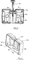
- the trap has a housing 2 from which there depends, in the set position, two wire loops 4 and a trigger 6.
- the bottom end wall 8 of the housing is arranged above the tunnel so that the wire loops 4 and the trigger 6 extend into the tunnel.
- the tunnel provides a path, defined beneath the housing 2, through which the animal moves.
- opposed walls of the housing 2 can be extended as indicated by dotted lines at 10 in Figure 2 .
- the housing can then be supported on the extended walls 10 to define a path, containing the wire loops 4 and the trigger 6, along which an animal may venture or may be attracted by bait.
- the housing 2 has a support 12 extending therethrough.
- the support 12 has its longitudinal extent as shown on Figure 1 along the line C-C. As can be seen in Figure 5 , for example, the support 12 extends in a transverse plane D-D extending perpendicularly to the longitudinal extent C-C.
- the upper portion of the support 12 has a handle 14 which, and as illustrated, is gently curved as it extends along the transverse plane to facilitate handling.
- the support 12 is moulded, from plastics material, in one piece to define the trigger 6. It will be seen that the trigger 6 is joined to the support 12 at its one inner end 16. There is no other connection between the trigger 6 and the support 12.
- the trigger 6, which extends longitudinally, is shaped so that it has some flexibility in the direction perpendicular to the plane D-D as indicated by the arrows E-E on Figure 5 . Thus, the trigger 6, on flexing, can move in both directions along the path for the animal.
- the trigger 6 has two transverse shoulders 18 formed thereon. In the set position, each transverse shoulder 18 is engaged beneath a corresponding flange 20 which extends within the lower end wall 8 of the housing. Thus, the interengagement between the transverse shoulders 18 and the flanges 20 retains the trigger 6 in the set position illustrated in Figure 1 against the force of two torsion springs 22.
- Each of the torsion springs 22 is formed of a length of wire having a coil 24 and a first end 26 engaged with the housing.
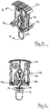
- the housing is formed with internal protuberances 28, which are visible in Figure 4 , and define a respective bore within which the first end 26 of each torsion spring can be engaged.
- the other, second, end 29 of each torsion spring engages within grooves 30 provided on each side of the lower end of the support 12. These grooves are apparent in Figure 6 .
- the housing 2 of the animal trap is made by assembling two half-shells 32 as illustrated in Figure 4 .
- These half-shells 32 are preferably identical and each has an opening 34 formed in a top wall thereof through which the support 12 will extend and an opening 36 provided in a lower end wall 8 thereof through which the trigger 6 extends. There are also grooves 38 in the lower end wall 8 through which the wire loops 4 extend.
- the trap is assembled in the fired position which is illustrated in Figure 3 .
- the support 12 is positioned so that its longitudinal extent extends through the groove 34 in the top wall of one half-shell 32.
- the two torsion springs 22 are then placed in position.
- the first end 26 of each spring 22 is inserted in the bore of the respective protuberance 28 of the housing and the second end 29 of each spring 22 is extended through a respective groove 30 in the support 12.
- the first ends 26 of the two torsion springs 22 extend in opposite directions.
- the two torsion springs 22 bias the support 12 in opposite directions in a plane D-D extending perpendicularly to the longitudinal extent of the support 12.
- the support 12 is stably held within the half-shell.
- each wire loop 4 extends through the respective groove 38 in the lower end wall 8 of the housing and the two ends of each wire loop are engaged in holes 50 therefor which are provided near the base of the support 12.
- a second half-shell 32 can then be mounted onto the first half-shell.
- the edges of the half-shells can be provided with appropriate interengagements.
- projections 42 with bores are provided internally of the half-shells for receiving screws so that the two halves can be screwed together.
- the two openings 34 in the top wall of the completed housing 2 cooperate to form a groove through which the support 12 extends.
- the two openings 36 form a hole in the lower end wall 8 through which the trigger 6 will protrude once the trap has been set.
- the wire loops 4 will similarly protrude through the grooves 38.
- Each half-shell 32 forming the housing 2 has two parallel guide ribs extending along the height of the inside of the half-shell. During movement of the support 12 upwardly and downwardly through the housing, two opposed mouldings, provided near the base of the support 12, move along the guide ribs, and are guided thereby.
- the support 12 also has flexible protuberances near the base thereof. When the support 12 is moved to its set position, guided by the mouldings and guide ribs, the protuberances engage on mouldings within the housing 2. If the support 12 is pushed too far, the protuberances are flexed and urge the support 12 into its correct position.
- the trap as illustrated is used in the position shown in Figure 1 and is moved to this set position simply by pressing down on the handle 14 of the support 12 such that the trigger 6 extends through the bottom surface of the housing to depend therefrom.
- the trigger 6 and support 12 are held in this position by the engagement of the shoulders 18 of the trigger 6 underneath the flanges 20 of the lower end wall 8 of the housing.
- teeth or other structures on the lower end wall 8 of the housing 2 to cooperate with the wire loops and enhance the killing effect.
- an animal trap as described and illustrated herein is that it is not affected in any way by gravity. This means that it can be set when oriented in any direction.
- the trigger can flex in both directions along the path along which the animal will move. This is achieved by giving flexibility to the trigger, as described above, by having the trigger fixed at one of its ends to provide a cantilever construction.
- the trigger formed in one piece with either the support it is possible to fix the trigger to the housing or the support by any appropriate means, for example by the use of one or more springs, clips or elastic connectors.
- the trigger can move upwardly and downwardly in the path so that it would be lifted by an animal moving along the path.
- the trap is described herein with specific reference to a killing trap.
- the explosive nature of the triggering means that the trap is very suitable for this.
Landscapes
- Life Sciences & Earth Sciences (AREA)
- Pest Control & Pesticides (AREA)
- Engineering & Computer Science (AREA)
- Insects & Arthropods (AREA)
- Wood Science & Technology (AREA)
- Zoology (AREA)
- Environmental Sciences (AREA)
- Catching Or Destruction (AREA)
Claims (8)
- Tierfalle, umfassend ein Gehäuse (2), eine Stütze (12) in dem Gehäuse (2), wobei die Stütze (12) zwischen einer ersten, festgesetzten Stellung und einer zweiten, ausgelösten Stellung bewegbar ist, Vorspannmittel zum Vorspannen der Stütze (12) zur zweiten, ausgelösten Stellung, und Mittel zum Halten der Stütze (12) in der ersten, festgesetzten Stellung gegen die Kraft der Vorspannmittel, wobei die Tierfalle ferner mindestens ein Fallenbetätigungselement (4) umfasst, das von der Stütze (12) getragen wird und damit bewegbar ist, wobei die Mittel zum Halten der Stütze (12) in der ersten, festgesetzten Stellung ineinandergreifende Mittel umfassen, die dafür angeordnet sind, durch die Bewegung eines länglichen Auslösers (6), der sich in einen Weg für ein Tier erstreckt, aus ihrer ineinandergreifenden Stellung bewegt zu werden, und wobei der Auslöser (6) von der Stütze (12) getragen wird und der Auslöser (6) nur an einem seiner Enden (16) an der Stütze (12) befestigt ist, sodass er sich biegen und dadurch in zwei entgegengesetzte Richtungen in Bezug auf den Weg für das Tier bewegt werden kann, und wobei die ineinandergreifenden Mittel eine oder mehrere quer verlaufende Schultern (18) umfassen, die an dem länglichen Auslöserelement (6) gebildet sind, welche in der ersten, festgesetzten Stellung dafür angeordnet sind, in entsprechende Flansche (20) einzugreifen, die an dem Gehäuse (2) vorgesehen sind.
- Tierfalle nach Anspruch 1, wobei der Auslöser (6) und die Stütze (12) in einem Stück aus Kunststoffmaterial abgeformt sind.
- Tierfalle nach einem vorhergehenden Anspruch, wobei die Vorspannmittel zwei Torsionsfedern (22) umfassen, die in dem Gehäuse (2) an entgegengesetzten Seiten der Stütze (12) angeordnet sind, wobei jede Torsionsfeder (22) ein erstes Ende (26) im Eingriff mit dem Gehäuse (2) und ein zweites (29) Ende im Eingriff mit der entsprechenden Seite der Stütze (12) aufweist.
- Tierfalle nach einem vorhergehenden Anspruch, wobei das Gehäuse (2) zwei abgeformte Halbschalen (32) umfasst, die zum Befestigen aneinander angeordnet sind, wobei die zwei Halbschalen, die das Gehäuse (2) bilden, im Wesentlichen identisch sind.
- Tierfalle nach einem vorhergehenden Anspruch, wobei die Vorspannmittel zwei Torsionsfedern (22) umfassen, die in dem Gehäuse (2) an entgegengesetzten Seiten der Stütze (12) angeordnet sind, wobei jede Torsionsfeder (22) eine Drahtlänge ist, die eine Windung (24) bildet, und ein erstes Ende (26) im Eingriff mit dem Gehäuse (2) und ein zweites Ende (29) im Eingriff mit der entsprechenden Seite der Stütze (12) aufweist, wobei die zwei Torsionsfedern derart angeordnet sind, dass sich ihre ersten Enden (26) in entgegengesetzte Richtungen erstrecken.
- Tierfalle nach einem vorhergehenden Anspruch, ferner umfassend zwei Fallenbetätigungselemente (4), die von der Stütze (12) getragen werden, wobei jedes Fallenbetätigungselement eine Drahtlänge umfasst, die zum Bilden eines sich von dem Gehäuse (2) erstreckenden Drahtrings gebogen ist, wobei die Enden jedes Drahtrings in der Stütze (12) im Eingriff sind und dafür angeordnet sind, auf ein Tier einzuwirken, wenn die Falle ausgelöst wird.
- Tierfalle nach Anspruch 6, wobei der Auslöser (6) und die zwei Drahtringe (4) in der ersten, festgesetzten Stellung über eine erste Endwand des Gehäuses (2) vorstehen.
- Tierfalle nach einem vorhergehenden Anspruch, wobei das Innere des Gehäuses (2) mit Führungsrippen oder -rillen versehen ist, um die Bewegung der Stütze (12) zu lenken.
Applications Claiming Priority (2)
| Application Number | Priority Date | Filing Date | Title |
|---|---|---|---|
| GB1219668.9A GB2509299B (en) | 2012-11-01 | 2012-11-01 | An animal trap |
| PCT/GB2013/052860 WO2014083308A1 (en) | 2012-11-01 | 2013-11-01 | An animal trap |
Publications (2)
| Publication Number | Publication Date |
|---|---|
| EP2914103A1 EP2914103A1 (de) | 2015-09-09 |
| EP2914103B1 true EP2914103B1 (de) | 2019-05-08 |
Family
ID=47359012
Family Applications (1)
| Application Number | Title | Priority Date | Filing Date |
|---|---|---|---|
| EP13792057.5A Active EP2914103B1 (de) | 2012-11-01 | 2013-11-01 | Tierfalle |
Country Status (4)
| Country | Link |
|---|---|
| US (1) | US9497957B2 (de) |
| EP (1) | EP2914103B1 (de) |
| GB (1) | GB2509299B (de) |
| WO (1) | WO2014083308A1 (de) |
Families Citing this family (1)
| Publication number | Priority date | Publication date | Assignee | Title |
|---|---|---|---|---|
| US8640379B2 (en) * | 2010-07-02 | 2014-02-04 | Senoret Chemical Company | Mole trap and method of operation therefor |
Family Cites Families (15)
| Publication number | Priority date | Publication date | Assignee | Title |
|---|---|---|---|---|
| US225144A (en) * | 1880-03-02 | Animal-trap | ||
| US1344807A (en) * | 1918-09-13 | 1920-06-29 | Maron August | Gopher-trap |
| US1701261A (en) * | 1927-10-24 | 1929-02-05 | Fox John | Animal trap |
| US1918582A (en) * | 1932-04-19 | 1933-07-18 | Alvau Frank | Animal trap |
| US2099021A (en) * | 1936-02-24 | 1937-11-16 | George M Landes | Rodent trap |
| US2348002A (en) * | 1942-02-09 | 1944-05-02 | Charles B Glass | Trap for gophers, rats, and similar rodents |
| US2475467A (en) * | 1947-08-23 | 1949-07-05 | Frank M Alvan | Animal trap |
| DE877229C (de) * | 1951-05-12 | 1953-05-21 | Walter Von Der Gathen | Doppelseitige Falle zum Fangen von Kleintieren in ihren Erdgaengen |
| NL8000408A (nl) * | 1980-01-22 | 1981-08-17 | Pot Antonius J P | Mollenklem met beveiliging. |
| US5746020A (en) * | 1994-06-13 | 1998-05-05 | Woodstream Corporation | Rubber band and spring powered mousetraps |
| US5692336A (en) * | 1994-06-13 | 1997-12-02 | Woodstream Corporation | Rubber band powered mousetrap |
| US7069688B2 (en) * | 2003-04-08 | 2006-07-04 | Daniel J. Hill | Animal trap |
| US20070068065A1 (en) * | 2005-09-28 | 2007-03-29 | Brown Elgin G Jr | Mole trapping system, mole trap and trap-setting assistance device, and methods of constructing and utilizing same |
| US8042299B1 (en) * | 2005-09-28 | 2011-10-25 | Brown Jr Elgin Glen | Mole trap |
| DE502006009005D1 (de) | 2006-09-01 | 2011-04-14 | Swissinno Solutions Gmbh | Tierfalle |
-
2012
- 2012-11-01 GB GB1219668.9A patent/GB2509299B/en active Active
-
2013
- 2013-11-01 WO PCT/GB2013/052860 patent/WO2014083308A1/en not_active Ceased
- 2013-11-01 EP EP13792057.5A patent/EP2914103B1/de active Active
- 2013-11-01 US US14/440,201 patent/US9497957B2/en active Active
Non-Patent Citations (1)
| Title |
|---|
| None * |
Also Published As
| Publication number | Publication date |
|---|---|
| US9497957B2 (en) | 2016-11-22 |
| EP2914103A1 (de) | 2015-09-09 |
| US20150272108A1 (en) | 2015-10-01 |
| GB2509299A (en) | 2014-07-02 |
| GB201219668D0 (en) | 2012-12-12 |
| WO2014083308A1 (en) | 2014-06-05 |
| GB2509299B (en) | 2017-04-19 |
Similar Documents
| Publication | Publication Date | Title |
|---|---|---|
| US8640379B2 (en) | Mole trap and method of operation therefor | |
| US7793460B2 (en) | Animal trap | |
| US4557067A (en) | Animal trap | |
| US8490323B2 (en) | Rodent trap having a pivoting platform | |
| US20100031555A1 (en) | Animal Trap | |
| EP2230902B1 (de) | Falle für nagetiere mit einer schwenkplattform | |
| US20210244012A1 (en) | Animal trap | |
| EP2312942A1 (de) | Falle für nagetiere mit einer schwenkplattform | |
| CN111887240A (zh) | 易于设置的隧道式动物捕捉器 | |
| US9497957B2 (en) | Animal trap | |
| US20160135444A1 (en) | Quick setting trap with enhanced safety features | |
| US10893670B2 (en) | Animal trap | |
| US20190082674A1 (en) | Fly swatter | |
| EP2230903A1 (de) | Nagerfalle mit einer schlinge | |
| US4735011A (en) | Humane animal trap | |
| CN216358222U (zh) | 诱捕装置 | |
| KR102281264B1 (ko) | 두더지 포획용 덫 | |
| US384415A (en) | Animal-trap | |
| KR200249127Y1 (ko) | 두더지 덫 | |
| US241990A (en) | Animal-trap | |
| WO2008073121A3 (en) | Insect trap | |
| NZ755358B2 (en) | Rodent trap having a pivoting platform | |
| JP2008017737A (ja) | 昆虫捕獲器 |
Legal Events
| Date | Code | Title | Description |
|---|---|---|---|
| PUAI | Public reference made under article 153(3) epc to a published international application that has entered the european phase |
Free format text: ORIGINAL CODE: 0009012 |
|
| 17P | Request for examination filed |
Effective date: 20150514 |
|
| AK | Designated contracting states |
Kind code of ref document: A1 Designated state(s): AL AT BE BG CH CY CZ DE DK EE ES FI FR GB GR HR HU IE IS IT LI LT LU LV MC MK MT NL NO PL PT RO RS SE SI SK SM TR |
|
| AX | Request for extension of the european patent |
Extension state: BA ME |
|
| DAX | Request for extension of the european patent (deleted) | ||
| GRAP | Despatch of communication of intention to grant a patent |
Free format text: ORIGINAL CODE: EPIDOSNIGR1 |
|
| STAA | Information on the status of an ep patent application or granted ep patent |
Free format text: STATUS: GRANT OF PATENT IS INTENDED |
|
| INTG | Intention to grant announced |
Effective date: 20181204 |
|
| GRAS | Grant fee paid |
Free format text: ORIGINAL CODE: EPIDOSNIGR3 |
|
| GRAA | (expected) grant |
Free format text: ORIGINAL CODE: 0009210 |
|
| STAA | Information on the status of an ep patent application or granted ep patent |
Free format text: STATUS: THE PATENT HAS BEEN GRANTED |
|
| AK | Designated contracting states |
Kind code of ref document: B1 Designated state(s): AL AT BE BG CH CY CZ DE DK EE ES FI FR GR HR HU IE IS IT LI LT LU LV MC MK MT NL NO PL PT RO RS SE SI SK SM TR |
|
| RBV | Designated contracting states (corrected) |
Designated state(s): AL AT BE BG CH CY CZ DE DK EE ES FI FR GR HR HU IE IS IT LI LT LU LV MC MK MT NL NO PL PT RO RS SE SI SK SM TR |
|
| REG | Reference to a national code |
Ref country code: CH Ref legal event code: EP Ref country code: AT Ref legal event code: REF Ref document number: 1128730 Country of ref document: AT Kind code of ref document: T Effective date: 20190515 |
|
| REG | Reference to a national code |
Ref country code: DE Ref legal event code: R096 Ref document number: 602013055124 Country of ref document: DE Ref country code: IE Ref legal event code: FG4D |
|
| REG | Reference to a national code |
Ref country code: NL Ref legal event code: MP Effective date: 20190508 |
|
| REG | Reference to a national code |
Ref country code: LT Ref legal event code: MG4D |
|
| PG25 | Lapsed in a contracting state [announced via postgrant information from national office to epo] |
Ref country code: SE Free format text: LAPSE BECAUSE OF FAILURE TO SUBMIT A TRANSLATION OF THE DESCRIPTION OR TO PAY THE FEE WITHIN THE PRESCRIBED TIME-LIMIT Effective date: 20190508 Ref country code: PT Free format text: LAPSE BECAUSE OF FAILURE TO SUBMIT A TRANSLATION OF THE DESCRIPTION OR TO PAY THE FEE WITHIN THE PRESCRIBED TIME-LIMIT Effective date: 20190908 Ref country code: HR Free format text: LAPSE BECAUSE OF FAILURE TO SUBMIT A TRANSLATION OF THE DESCRIPTION OR TO PAY THE FEE WITHIN THE PRESCRIBED TIME-LIMIT Effective date: 20190508 Ref country code: AL Free format text: LAPSE BECAUSE OF FAILURE TO SUBMIT A TRANSLATION OF THE DESCRIPTION OR TO PAY THE FEE WITHIN THE PRESCRIBED TIME-LIMIT Effective date: 20190508 Ref country code: FI Free format text: LAPSE BECAUSE OF FAILURE TO SUBMIT A TRANSLATION OF THE DESCRIPTION OR TO PAY THE FEE WITHIN THE PRESCRIBED TIME-LIMIT Effective date: 20190508 Ref country code: NO Free format text: LAPSE BECAUSE OF FAILURE TO SUBMIT A TRANSLATION OF THE DESCRIPTION OR TO PAY THE FEE WITHIN THE PRESCRIBED TIME-LIMIT Effective date: 20190808 Ref country code: NL Free format text: LAPSE BECAUSE OF FAILURE TO SUBMIT A TRANSLATION OF THE DESCRIPTION OR TO PAY THE FEE WITHIN THE PRESCRIBED TIME-LIMIT Effective date: 20190508 Ref country code: ES Free format text: LAPSE BECAUSE OF FAILURE TO SUBMIT A TRANSLATION OF THE DESCRIPTION OR TO PAY THE FEE WITHIN THE PRESCRIBED TIME-LIMIT Effective date: 20190508 Ref country code: LT Free format text: LAPSE BECAUSE OF FAILURE TO SUBMIT A TRANSLATION OF THE DESCRIPTION OR TO PAY THE FEE WITHIN THE PRESCRIBED TIME-LIMIT Effective date: 20190508 |
|
| PG25 | Lapsed in a contracting state [announced via postgrant information from national office to epo] |
Ref country code: BG Free format text: LAPSE BECAUSE OF FAILURE TO SUBMIT A TRANSLATION OF THE DESCRIPTION OR TO PAY THE FEE WITHIN THE PRESCRIBED TIME-LIMIT Effective date: 20190808 Ref country code: RS Free format text: LAPSE BECAUSE OF FAILURE TO SUBMIT A TRANSLATION OF THE DESCRIPTION OR TO PAY THE FEE WITHIN THE PRESCRIBED TIME-LIMIT Effective date: 20190508 Ref country code: LV Free format text: LAPSE BECAUSE OF FAILURE TO SUBMIT A TRANSLATION OF THE DESCRIPTION OR TO PAY THE FEE WITHIN THE PRESCRIBED TIME-LIMIT Effective date: 20190508 Ref country code: GR Free format text: LAPSE BECAUSE OF FAILURE TO SUBMIT A TRANSLATION OF THE DESCRIPTION OR TO PAY THE FEE WITHIN THE PRESCRIBED TIME-LIMIT Effective date: 20190809 |
|
| REG | Reference to a national code |
Ref country code: AT Ref legal event code: MK05 Ref document number: 1128730 Country of ref document: AT Kind code of ref document: T Effective date: 20190508 |
|
| PG25 | Lapsed in a contracting state [announced via postgrant information from national office to epo] |
Ref country code: AT Free format text: LAPSE BECAUSE OF FAILURE TO SUBMIT A TRANSLATION OF THE DESCRIPTION OR TO PAY THE FEE WITHIN THE PRESCRIBED TIME-LIMIT Effective date: 20190508 Ref country code: DK Free format text: LAPSE BECAUSE OF FAILURE TO SUBMIT A TRANSLATION OF THE DESCRIPTION OR TO PAY THE FEE WITHIN THE PRESCRIBED TIME-LIMIT Effective date: 20190508 Ref country code: EE Free format text: LAPSE BECAUSE OF FAILURE TO SUBMIT A TRANSLATION OF THE DESCRIPTION OR TO PAY THE FEE WITHIN THE PRESCRIBED TIME-LIMIT Effective date: 20190508 Ref country code: RO Free format text: LAPSE BECAUSE OF FAILURE TO SUBMIT A TRANSLATION OF THE DESCRIPTION OR TO PAY THE FEE WITHIN THE PRESCRIBED TIME-LIMIT Effective date: 20190508 Ref country code: SK Free format text: LAPSE BECAUSE OF FAILURE TO SUBMIT A TRANSLATION OF THE DESCRIPTION OR TO PAY THE FEE WITHIN THE PRESCRIBED TIME-LIMIT Effective date: 20190508 Ref country code: CZ Free format text: LAPSE BECAUSE OF FAILURE TO SUBMIT A TRANSLATION OF THE DESCRIPTION OR TO PAY THE FEE WITHIN THE PRESCRIBED TIME-LIMIT Effective date: 20190508 |
|
| REG | Reference to a national code |
Ref country code: DE Ref legal event code: R097 Ref document number: 602013055124 Country of ref document: DE |
|
| PG25 | Lapsed in a contracting state [announced via postgrant information from national office to epo] |
Ref country code: SM Free format text: LAPSE BECAUSE OF FAILURE TO SUBMIT A TRANSLATION OF THE DESCRIPTION OR TO PAY THE FEE WITHIN THE PRESCRIBED TIME-LIMIT Effective date: 20190508 Ref country code: IT Free format text: LAPSE BECAUSE OF FAILURE TO SUBMIT A TRANSLATION OF THE DESCRIPTION OR TO PAY THE FEE WITHIN THE PRESCRIBED TIME-LIMIT Effective date: 20190508 |
|
| PLBE | No opposition filed within time limit |
Free format text: ORIGINAL CODE: 0009261 |
|
| STAA | Information on the status of an ep patent application or granted ep patent |
Free format text: STATUS: NO OPPOSITION FILED WITHIN TIME LIMIT |
|
| PG25 | Lapsed in a contracting state [announced via postgrant information from national office to epo] |
Ref country code: TR Free format text: LAPSE BECAUSE OF FAILURE TO SUBMIT A TRANSLATION OF THE DESCRIPTION OR TO PAY THE FEE WITHIN THE PRESCRIBED TIME-LIMIT Effective date: 20190508 |
|
| 26N | No opposition filed |
Effective date: 20200211 |
|
| PG25 | Lapsed in a contracting state [announced via postgrant information from national office to epo] |
Ref country code: PL Free format text: LAPSE BECAUSE OF FAILURE TO SUBMIT A TRANSLATION OF THE DESCRIPTION OR TO PAY THE FEE WITHIN THE PRESCRIBED TIME-LIMIT Effective date: 20190508 |
|
| PG25 | Lapsed in a contracting state [announced via postgrant information from national office to epo] |
Ref country code: SI Free format text: LAPSE BECAUSE OF FAILURE TO SUBMIT A TRANSLATION OF THE DESCRIPTION OR TO PAY THE FEE WITHIN THE PRESCRIBED TIME-LIMIT Effective date: 20190508 |
|
| REG | Reference to a national code |
Ref country code: CH Ref legal event code: PL |
|
| PG25 | Lapsed in a contracting state [announced via postgrant information from national office to epo] |
Ref country code: LU Free format text: LAPSE BECAUSE OF NON-PAYMENT OF DUE FEES Effective date: 20191101 Ref country code: LI Free format text: LAPSE BECAUSE OF NON-PAYMENT OF DUE FEES Effective date: 20191130 Ref country code: MC Free format text: LAPSE BECAUSE OF FAILURE TO SUBMIT A TRANSLATION OF THE DESCRIPTION OR TO PAY THE FEE WITHIN THE PRESCRIBED TIME-LIMIT Effective date: 20190508 Ref country code: CH Free format text: LAPSE BECAUSE OF NON-PAYMENT OF DUE FEES Effective date: 20191130 |
|
| REG | Reference to a national code |
Ref country code: BE Ref legal event code: MM Effective date: 20191130 |
|
| PG25 | Lapsed in a contracting state [announced via postgrant information from national office to epo] |
Ref country code: IE Free format text: LAPSE BECAUSE OF NON-PAYMENT OF DUE FEES Effective date: 20191101 |
|
| PG25 | Lapsed in a contracting state [announced via postgrant information from national office to epo] |
Ref country code: BE Free format text: LAPSE BECAUSE OF NON-PAYMENT OF DUE FEES Effective date: 20191130 |
|
| PG25 | Lapsed in a contracting state [announced via postgrant information from national office to epo] |
Ref country code: CY Free format text: LAPSE BECAUSE OF FAILURE TO SUBMIT A TRANSLATION OF THE DESCRIPTION OR TO PAY THE FEE WITHIN THE PRESCRIBED TIME-LIMIT Effective date: 20190508 |
|
| PG25 | Lapsed in a contracting state [announced via postgrant information from national office to epo] |
Ref country code: IS Free format text: LAPSE BECAUSE OF FAILURE TO SUBMIT A TRANSLATION OF THE DESCRIPTION OR TO PAY THE FEE WITHIN THE PRESCRIBED TIME-LIMIT Effective date: 20190908 |
|
| PG25 | Lapsed in a contracting state [announced via postgrant information from national office to epo] |
Ref country code: MT Free format text: LAPSE BECAUSE OF FAILURE TO SUBMIT A TRANSLATION OF THE DESCRIPTION OR TO PAY THE FEE WITHIN THE PRESCRIBED TIME-LIMIT Effective date: 20190508 Ref country code: HU Free format text: LAPSE BECAUSE OF FAILURE TO SUBMIT A TRANSLATION OF THE DESCRIPTION OR TO PAY THE FEE WITHIN THE PRESCRIBED TIME-LIMIT; INVALID AB INITIO Effective date: 20131101 |
|
| PG25 | Lapsed in a contracting state [announced via postgrant information from national office to epo] |
Ref country code: MK Free format text: LAPSE BECAUSE OF FAILURE TO SUBMIT A TRANSLATION OF THE DESCRIPTION OR TO PAY THE FEE WITHIN THE PRESCRIBED TIME-LIMIT Effective date: 20190508 |
|
| PGFP | Annual fee paid to national office [announced via postgrant information from national office to epo] |
Ref country code: DE Payment date: 20251014 Year of fee payment: 13 |
|
| PGFP | Annual fee paid to national office [announced via postgrant information from national office to epo] |
Ref country code: FR Payment date: 20251023 Year of fee payment: 13 |