EP2913891B1 - Sender/empfänger-vorrichtung - Google Patents
Sender/empfänger-vorrichtung Download PDFInfo
- Publication number
- EP2913891B1 EP2913891B1 EP13894939.1A EP13894939A EP2913891B1 EP 2913891 B1 EP2913891 B1 EP 2913891B1 EP 13894939 A EP13894939 A EP 13894939A EP 2913891 B1 EP2913891 B1 EP 2913891B1
- Authority
- EP
- European Patent Office
- Prior art keywords
- transmitter
- receiver
- apas
- dimensional
- radar
- Prior art date
- Legal status (The legal status is an assumption and is not a legal conclusion. Google has not performed a legal analysis and makes no representation as to the accuracy of the status listed.)
- Not-in-force
Links
Images


Classifications
-
- H—ELECTRICITY
- H04—ELECTRIC COMMUNICATION TECHNIQUE
- H04B—TRANSMISSION
- H04B1/00—Details of transmission systems, not covered by a single one of groups H04B3/00 - H04B13/00; Details of transmission systems not characterised by the medium used for transmission
- H04B1/38—Transceivers, i.e. devices in which transmitter and receiver form a structural unit and in which at least one part is used for functions of transmitting and receiving
- H04B1/40—Circuits
- H04B1/50—Circuits using different frequencies for the two directions of communication
-
- H—ELECTRICITY
- H01—ELECTRIC ELEMENTS
- H01Q—ANTENNAS, i.e. RADIO AERIALS
- H01Q21/00—Antenna arrays or systems
- H01Q21/06—Arrays of individually energised antenna units similarly polarised and spaced apart
- H01Q21/061—Two dimensional planar arrays
-
- G—PHYSICS
- G01—MEASURING; TESTING
- G01S—RADIO DIRECTION-FINDING; RADIO NAVIGATION; DETERMINING DISTANCE OR VELOCITY BY USE OF RADIO WAVES; LOCATING OR PRESENCE-DETECTING BY USE OF THE REFLECTION OR RERADIATION OF RADIO WAVES; ANALOGOUS ARRANGEMENTS USING OTHER WAVES
- G01S7/00—Details of systems according to groups G01S13/00, G01S15/00, G01S17/00
- G01S7/02—Details of systems according to groups G01S13/00, G01S15/00, G01S17/00 of systems according to group G01S13/00
- G01S7/03—Details of HF subsystems specially adapted therefor, e.g. common to transmitter and receiver
- G01S7/032—Constructional details for solid-state radar subsystems
-
- H—ELECTRICITY
- H01—ELECTRIC ELEMENTS
- H01Q—ANTENNAS, i.e. RADIO AERIALS
- H01Q1/00—Details of, or arrangements associated with, antennas
- H01Q1/52—Means for reducing coupling between antennas; Means for reducing coupling between an antenna and another structure
- H01Q1/521—Means for reducing coupling between antennas; Means for reducing coupling between an antenna and another structure reducing the coupling between adjacent antennas
- H01Q1/523—Means for reducing coupling between antennas; Means for reducing coupling between an antenna and another structure reducing the coupling between adjacent antennas between antennas of an array
-
- H—ELECTRICITY
- H01—ELECTRIC ELEMENTS
- H01Q—ANTENNAS, i.e. RADIO AERIALS
- H01Q21/00—Antenna arrays or systems
- H01Q21/0006—Particular feeding systems
- H01Q21/0025—Modular arrays
-
- H—ELECTRICITY
- H01—ELECTRIC ELEMENTS
- H01Q—ANTENNAS, i.e. RADIO AERIALS
- H01Q21/00—Antenna arrays or systems
- H01Q21/06—Arrays of individually energised antenna units similarly polarised and spaced apart
- H01Q21/20—Arrays of individually energised antenna units similarly polarised and spaced apart the units being spaced along or adjacent to a curvilinear path
- H01Q21/205—Arrays of individually energised antenna units similarly polarised and spaced apart the units being spaced along or adjacent to a curvilinear path providing an omnidirectional coverage
-
- H—ELECTRICITY
- H01—ELECTRIC ELEMENTS
- H01Q—ANTENNAS, i.e. RADIO AERIALS
- H01Q25/00—Antennas or antenna systems providing at least two radiating patterns
- H01Q25/005—Antennas or antenna systems providing at least two radiating patterns providing two patterns of opposite direction; back to back antennas
-
- H—ELECTRICITY
- H01—ELECTRIC ELEMENTS
- H01Q—ANTENNAS, i.e. RADIO AERIALS
- H01Q3/00—Arrangements for changing or varying the orientation or the shape of the directional pattern of the waves radiated from an antenna or antenna system
- H01Q3/26—Arrangements for changing or varying the orientation or the shape of the directional pattern of the waves radiated from an antenna or antenna system varying the relative phase or relative amplitude of energisation between two or more active radiating elements; varying the distribution of energy across a radiating aperture
- H01Q3/30—Arrangements for changing or varying the orientation or the shape of the directional pattern of the waves radiated from an antenna or antenna system varying the relative phase or relative amplitude of energisation between two or more active radiating elements; varying the distribution of energy across a radiating aperture varying the relative phase between the radiating elements of an array
- H01Q3/34—Arrangements for changing or varying the orientation or the shape of the directional pattern of the waves radiated from an antenna or antenna system varying the relative phase or relative amplitude of energisation between two or more active radiating elements; varying the distribution of energy across a radiating aperture varying the relative phase between the radiating elements of an array by electrical means
-
- G—PHYSICS
- G01—MEASURING; TESTING
- G01S—RADIO DIRECTION-FINDING; RADIO NAVIGATION; DETERMINING DISTANCE OR VELOCITY BY USE OF RADIO WAVES; LOCATING OR PRESENCE-DETECTING BY USE OF THE REFLECTION OR RERADIATION OF RADIO WAVES; ANALOGOUS ARRANGEMENTS USING OTHER WAVES
- G01S13/00—Systems using the reflection or reradiation of radio waves, e.g. radar systems; Analogous systems using reflection or reradiation of waves whose nature or wavelength is irrelevant or unspecified
- G01S13/02—Systems using reflection of radio waves, e.g. primary radar systems; Analogous systems
- G01S2013/0236—Special technical features
- G01S2013/0245—Radar with phased array antenna
- G01S2013/0254—Active array antenna
-
- H—ELECTRICITY
- H01—ELECTRIC ELEMENTS
- H01Q—ANTENNAS, i.e. RADIO AERIALS
- H01Q3/00—Arrangements for changing or varying the orientation or the shape of the directional pattern of the waves radiated from an antenna or antenna system
- H01Q3/26—Arrangements for changing or varying the orientation or the shape of the directional pattern of the waves radiated from an antenna or antenna system varying the relative phase or relative amplitude of energisation between two or more active radiating elements; varying the distribution of energy across a radiating aperture
Definitions
- the present invention relates to the technology of active phased arrays (APA) and can find a wide application to build radar stations for mobile or stationary objects as well as in communication systems.
- APA active phased arrays
- the two-face phased arrays are made unidimensional or two-dimensional, they are arranged in the horizontal plane at an angle of 75 - 105° to each other while keeping the capability of all-around looking, the transmit-receive module is provided with an additional phase shifter, each one of both phase shifters being permanently connected, via a selector switch, to one of the receivers or to the transmitter, and the transmitter is connected, via a selector switch and a circulator, to the radiating elements with the possibility to be alternately connected to the radiating elements with the use of different frequencies and/or with the use of a different signal coding, corresponding to different frequencies and coding of the receivers receiving mode with the capability to form at least two independent beams in opposite directions, the active two-side phase shifter, each one of both phase shifters being permanently connected, via a selector switch, to one of the receivers or to the transmitter, and the transmitter is connected, via a selector switch and a circulator, to the radiating elements with the possibility to be alternately connected to the radiating elements with
- the receiver-transmitter can be additionally provided with at least one radar or communication station located above and/or below the receiver-transmitter, made with the capability to scan in two planes in order to radiate upwards and/or downwards.
- the radar or communication station can be made as a two-dimensional active one-side phased array or as a two-dimensional active two-side phased array with transmit-receive modules described in claim 1, arranged with a shift relative to the receiver-transmitter in the horizontal and vertical planes.
- TRMs In the last decades, the use of APAs in radar and communications systems has become very widespread. However, the costs of TRMs are still rather high. At the same time, the TRM size goes down thanks to the modern high-frequency integrated-circuit technologies such as the Monolithic Microwave Integrated Circuit (MMIC). The reduced size of TRMs enables to easily build devices according to the present invention.
- MMIC Monolithic Microwave Integrated Circuit
- a traditional solution to build a radar or communications system when the all-around looking is required, lies in the use of four APAs each one of them carrying out ⁇ 45 - 60 0 scanning in the horizontal and vertical planes. Consequently, to provide a relatively narrow pattern, for example 2° in any range, each APA will comprise more than 3000 APAs. In the case of four APAs, more than 12,000 APAs are required which enables to form four fully independent beams. Such radar is rather expensive.
- the device according to the claimed invention when keeping its energy potential and four independent beams, enables to reduce the cost of such radar, since about 80% of the cost relates to the TRM modules, the cost of an additional receiver and of a phase shifter being not high.
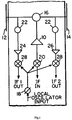
- FIG.1 shows an arrangement disclosed in the US patent 3,648,284 where 10 represents a transmitter, 12 and 14 are radiating elements, 16 is a selector switch, 18 is a phase shifter, 20 and 28 are mixers, 24 and 26 are receivers. It enables a two times reduction of the number of TRMs compared to radar systems using one-face phased arrays, but the energy potential will be lower than for the case of two independent one-side phased arrays. Due to the use of only one phase shifter for different directions, emission and reception of a signal with the same phase will occur, which does not enable to form completely independent beams.
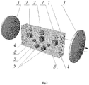
- FIG. 2 shows an arrangement where 1 represents a TRM, 2 is a switch, 3 represents a radiating element, 4 is a receiver, 5 is a transmitter, 7 represents a circulator, 8 represents a transmit-receipt selector switch, 9 represents phase shifters.
- Such an arrangement enables to simultaneously emit and to receive, thanks to the use of two independent phase shifters, signals of different directions and with different phases, and, consequently, enables to form completely independent beams on opposite APA panels, without loss of energy potential.
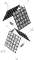
- FIG. 3 shows a radar or communications system composed of two unidimensional two-sided APAs mounted in an orthogonal way and comprising TRMs illustrated in FIG. 2 , that are operating in opposite directions.
- TRMs illustrated in FIG. 2
- Such an arrangement enables every array panel to scan ⁇ 45 - 60° with independent electronic beams in the horizontal plane in opposite directions, at the same time providing the all-around looking.
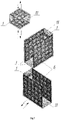
- Arranging 2 two-dimensional APAs in the orthogonal plane to each other enables the all-around looking in the horizontal plane and ⁇ 45 - 60 0 in the vertical plane with the help of independent beams from each APA panel ( FIG.4 ).
- Such an arrangement provides for the possibility of the all-around looking, for maintaining the energy potential and the formation of independent beams while using 6,000 TRMs instead of 12,000.
- unidimensional or two-dimensional two-faced APAs are mounted with some shift relative to each other in the vertical and/or horizontal planes with the possibility to take account of parallax mathematically.
- the radar with a traditional all-around looking APA has 12,000 TRMs of 1 W power and the on-off time ratio of 10 (operation time of 10%), its average power will be 1,200 W. While using the device according to the present invention for providing the all-around looking, only 6,000 TRMs of 1 W are required, but they will operate already for 20% of time, the average power of the whole system being equal to 1,000 watts as well.
- the transmitter transmits an impulse from the second panel and immediately the reception of reflected signal at the second panel starts. Since there is only one phase shifter, both panels operate at the same phase. After the first panel receives the full signal, it starts standing since the second panel has not still received completely the signal because the impulse has been sent later, and it is prohibited to change the phase. Only after the complete reception of the signal at the second panel, the phase can be changed and the next impulse be transmitted in another direction. Considering that modern radars use rather long impulses, the time losses will be important at a regular surveillance. Furthermore, modern radar systems with electronic beam scanning are used not only for regular space surveillance. At the detection of a target, the beam interrupts the regular surveillance and additionally processes these targets.
- the operation time for them increases because of the regular surveillance time.
- the phased array having a TRM with one phase shifter looses completely its efficiency while operating simultaneously in the opposite direction, since, most probably, there is no target in the same direction from the other side of the array.
- the opposite panel can continue to carry out regular surveillance or to operate on targets independently of the first panel.
- a phased array having a TRM with a single phase shifter is of low efficiency or is generally unusable for communications systems.
- Communications systems based on phased arrays are used to receive and to transmit data about specific targets located in known directions. While operating with a target from one side, it is unlikely to have another target from the other side in the same direction. In this case, the efficiency of the communications system will be extremely low, since when the operation on targets is carried out from one side, the other side will not operate at all. And in the case of using such a system as a repeater, it will not operate at all since it is necessary to continuously receive information from an object at one side and immediately to transmit this information to another object at the other side. It is extremely unlikely that the directions of these objects are the same.
- the device of the present invention for the upper hemisphere can be made as well with separate APA panels, for example, at an angle of 30 0 to the horizon, and, in this way, the whole looking in the vertical plane will cover all the upper hemisphere (see FIG. 5 ). But in this case, some problems related to losses can appear in the lower TRMs due to a rather high distance from the TRM to radiating elements.
- Another way to increase the looking area for preventing said drawback is the use of additional APAs.
- Detection of targets at such or lower distances can be provided by a single one-sided two-dimensional APA (8) composed of traditional TRMs having a low total energy potential, and mounted at the top in the way to emit in the upper looking sector (see FIG. 6 ).
- Such an APA must scan in two planes in the limits of ⁇ 45 - 60 0 .
- the total antenna pattern of such an APA will be presented as a part of a sphere with the aperture angle of 90 - 120 0 ( ⁇ 45 - 60 0 ) which will enable to monitor completely the whole upper hemisphere with the radar system.
- the aperture angle of 90 - 120 0 ⁇ 45 - 60 0
- such APAs are mounted at the top and underneath.
- such a two-dimensional APA can be composed of a significantly lower number of TRMs, for example 16 for 16 TRMs, which gives only 256 elements totally, nevertheless the antenna pattern of such an APA will be 8 0 by 8 0 , which will affect the radar system resolution in the upper and/or lower sectors, although the energy potential of such a radar system in these sectors will be quite sufficient.
- the radar system of the present invention while using an upper one-sided APA, will have 6,256 TRMs, whereas a radar system with four traditional APAs has 12,000 TRMs.
- a single two-dimensional two-sided APA can be used as well, having a TRM with a selector switch of the transmitter, two receivers and two phase shifters, mounted in the way to emit in the upper and lower looking sectors and having a shift in the horizontal and vertical planes relative to two perpendicular APAs, with the capability to take account of parallax mathematically (see FIG. 7 ).
- the radar system having a spherical looking area and an additional two-sided two-dimensional APA sized 16 by 16 TRMs will comprise 6,256 TRMs.
- a traditional design with a radar system composed of four APAs arranged at an angle to the horizon and of 12,000 TRMs shades the hemisphere and can not in general provide for a spherical looking area.
- FIG. 8 discloses an example of building a ship radar-communication mast with the use of two-sided unidimensional and two-dimensional APAs and of one-sided APAs to monitor the upper looking sectors.
- the ship radar-communication mast comprises a radioparent radome (30), a mast (31), two-sided two-dimensional APAs of a S-range radar (32), two-sided unidimensional APAs of S-range (33), two-sided two-dimensional APAs of a X-range radar (34), two-sided unidimensional APAs of a X-range communications system (35), one-sided two-dimensional APA of a X-range radar to monitor the upper looking sector (37).
- the structures disclosed in the device according to the present invention can find efficient use in hydroacoustics where active phased arrays are used as well and where 2-time reducing of the number of TRMs is of current interest too.
- the device according to the present invention can find application for radar, communications and hydroacoustic systems where APAs are used.
Landscapes
- Engineering & Computer Science (AREA)
- Radar, Positioning & Navigation (AREA)
- Remote Sensing (AREA)
- Computer Networks & Wireless Communication (AREA)
- Physics & Mathematics (AREA)
- General Physics & Mathematics (AREA)
- Signal Processing (AREA)
- Radar Systems Or Details Thereof (AREA)
- Variable-Direction Aerials And Aerial Arrays (AREA)
- Radio Transmission System (AREA)
Claims (5)
- Empfänger-Sender umfassend aktive zweiseitige phasengesteuerte Gruppenantennen (APAs) aufweisend Sende-Empfangs-Module (1), von denen jedes zwei Strahlungselemente (3), einen Sender (5), zwei Empfänger (4), zwei Trennschalter, Mischer, einen Phasenschieber umfasst, wobei die zweiseitigen phasengesteuerten Gruppenantennen eindimensional oder zweidimensional ausgebildet sind, wobei sie in der horizontalen Ebene in einem Winkel von 75 -105° zueinander angeordnet sind, während die Fähigkeit des Allround-Looks beibehalten wird,
dadurch gekennzeichnet, dass
das Sende-Empfangs-Modul (1) mit einem zusätzlichen Phasenschieber (9) versehen ist, wobei jeder der beiden Phasenschieber (9) über einen Auswahlschalter (8) mit einem der Empfänger (4) oder mit dem Sender (5) verbunden ist, und wobei der Sender (5) über einen Auswahlschalter (2) und Zirkulatoren (7) mit den Strahlungselementen (3) verbunden ist, wobei die Möglichkeit besteht, abwechselnd mit den Strahlungselementen (3) unter Verwendung unterschiedlicher Frequenzen und / oder unter Verwendung einer unterschiedlichen Signalcodierung verbunden zu werden, korrespondierend zu unterschiedlichen Frequenzen und den Empfangsempfangsmodus des Empfängers kodierend mit der Möglichkeit, mindestens zwei unabhängige Strahlen in entgegengesetzten Richtungen zu bilden, wobei die aktiven zweiseitigen phasengesteuerten Gruppenantennen in der horizontalen und / oder vertikalen Ebene zueinander verschoben sind. - Empfänger-Sender mit zweidimensionalen APAs nach Anspruch 1, wobei die Panels (6) jeder Seite der aktiven zweiseitigen phasengesteuerten Gruppenantenne in der vertikalen Ebene in einem Winkel zueinander angeordnet sein können.
- Empfänger-Sender mit zweidimensionalen APAs nach Anspruch 1, wobei er zusätzlich mit mindestens einer oberhalb und / oder unterhalb des Empfänger-Senders angeordneten Radar- oder Kommunikationsstation versehen ist, mit der Fähigkeit zur Abtastung in zwei Ebenen um nach oben und / oder nach unten abzustrahlen.
- Empfänger-Sender nach Anspruch 3, wobei die Radar- oder Kommunikationsstation als zweidimensionale aktive einseitige phasengesteuerte Gruppenantenne ausgebildet ist.
- Empfänger-Sender nach Anspruch 3, dadurch gekennzeichnet, wobei die Radar- oder Kommunikationsstation als zweidimensionale aktive zweiseitige phasengesteuerte Gruppenantenne mit den Sende-Empfangs-Modulen nach Anspruch 1 ausgebildet ist, angeordnet mit einer Verschiebung relativ zum Empfänger-Sender in den horizontalen und vertikalen Ebenen.
Applications Claiming Priority (2)
| Application Number | Priority Date | Filing Date | Title |
|---|---|---|---|
| RU2013154269 | 2013-12-06 | ||
| PCT/RU2013/001133 WO2015084208A1 (ru) | 2013-12-06 | 2013-12-18 | Приемопередающее устройство |
Publications (3)
| Publication Number | Publication Date |
|---|---|
| EP2913891A1 EP2913891A1 (de) | 2015-09-02 |
| EP2913891A4 EP2913891A4 (de) | 2016-10-12 |
| EP2913891B1 true EP2913891B1 (de) | 2017-10-11 |
Family
ID=53273816
Family Applications (1)
| Application Number | Title | Priority Date | Filing Date |
|---|---|---|---|
| EP13894939.1A Not-in-force EP2913891B1 (de) | 2013-12-06 | 2013-12-18 | Sender/empfänger-vorrichtung |
Country Status (16)
| Country | Link |
|---|---|
| US (1) | US9667305B2 (de) |
| EP (1) | EP2913891B1 (de) |
| JP (1) | JP6020945B2 (de) |
| KR (1) | KR101666329B1 (de) |
| CN (1) | CN104995796B (de) |
| AU (1) | AU2013405795B2 (de) |
| BR (1) | BR112015008969A2 (de) |
| CA (1) | CA2893735C (de) |
| DK (1) | DK2913891T3 (de) |
| EA (1) | EA027517B1 (de) |
| HK (1) | HK1214413A1 (de) |
| IL (1) | IL238230B (de) |
| MX (1) | MX352048B (de) |
| NO (1) | NO2913891T3 (de) |
| SG (1) | SG11201505777UA (de) |
| WO (1) | WO2015084208A1 (de) |
Families Citing this family (3)
| Publication number | Priority date | Publication date | Assignee | Title |
|---|---|---|---|---|
| RU172084U1 (ru) * | 2016-10-06 | 2017-06-28 | Акционерное общество "Всероссийский научно-исследовательский институт радиотехники" | Неподвижная антенная система рлс кругового обзора |
| KR102650731B1 (ko) * | 2019-04-23 | 2024-03-26 | 한국전자통신연구원 | 안테나 장치 |
| CN110429953B (zh) * | 2019-07-26 | 2024-04-19 | 中国科学院上海微系统与信息技术研究所 | 一种l型三频段抗干扰近距离探测器前端及其安装方法 |
Family Cites Families (17)
| Publication number | Priority date | Publication date | Assignee | Title |
|---|---|---|---|---|
| US3648284A (en) * | 1969-08-06 | 1972-03-07 | Westinghouse Electric Corp | Two-face phased array |
| US3854140A (en) * | 1973-07-25 | 1974-12-10 | Itt | Circularly polarized phased antenna array |
| US4791421A (en) * | 1986-09-10 | 1988-12-13 | Westinghouse Electric Corp. | Transmit-receive module for phased-array antennas |
| US4766438A (en) * | 1987-02-27 | 1988-08-23 | Hughes Aircraft Company | Three dimensional feed through lens with hemispherical coverage |
| US5027125A (en) * | 1989-08-16 | 1991-06-25 | Hughes Aircraft Company | Semi-active phased array antenna |
| US5283587A (en) * | 1992-11-30 | 1994-02-01 | Space Systems/Loral | Active transmit phased array antenna |
| US6496147B1 (en) * | 1998-12-14 | 2002-12-17 | Matsushita Electric Industrial Co., Ltd. | Active phased array antenna and antenna controller |
| RU2165665C1 (ru) * | 2000-07-24 | 2001-04-20 | Закрытое Акционерное Общество "Транзас" | Антенно-приемопередающая система радиолокационной станции |
| KR100844828B1 (ko) * | 2006-11-24 | 2008-07-08 | 주식회사알에프윈도우 | 안테나를 내장한 궤환 간섭신호 제거 무선중계장치 |
| RU2324950C1 (ru) * | 2006-12-18 | 2008-05-20 | Открытое акционерное общество "Научно-производственное предприятие "Радар ммс" | Антенно-приемопередающая система радиолокационной станции |
| US7791536B2 (en) * | 2007-06-24 | 2010-09-07 | Raytheon Company | High power phased array antenna system and method with low power switching |
| TWI520439B (zh) * | 2009-04-13 | 2016-02-01 | 凡爾賽特公司 | 半雙工相位陣列天線系統 |
| US8405548B2 (en) * | 2010-08-05 | 2013-03-26 | Raytheon Company | Multi-orientation phased antenna array and associated method |
| CN201852934U (zh) * | 2010-11-22 | 2011-06-01 | 南京恩瑞特实业有限公司 | 有源相控阵雷达用模块化收发组件 |
| US8665174B2 (en) * | 2011-01-13 | 2014-03-04 | The Boeing Company | Triangular phased array antenna subarray |
| KR101348452B1 (ko) * | 2012-01-11 | 2014-01-16 | 한국과학기술원 | 스위치 모드 빔성형 안테나의 다면체 배열 |
| US9455486B2 (en) * | 2013-07-03 | 2016-09-27 | The Boeing Company | Integrated circulator for phased arrays |
-
2013
- 2013-12-18 KR KR1020157011495A patent/KR101666329B1/ko active IP Right Grant
- 2013-12-18 SG SG11201505777UA patent/SG11201505777UA/en unknown
- 2013-12-18 CN CN201380060211.8A patent/CN104995796B/zh not_active Expired - Fee Related
- 2013-12-18 WO PCT/RU2013/001133 patent/WO2015084208A1/ru active Application Filing
- 2013-12-18 CA CA2893735A patent/CA2893735C/en not_active Expired - Fee Related
- 2013-12-18 AU AU2013405795A patent/AU2013405795B2/en not_active Ceased
- 2013-12-18 NO NO13894939A patent/NO2913891T3/no unknown
- 2013-12-18 DK DK13894939.1T patent/DK2913891T3/en active
- 2013-12-18 MX MX2015004403A patent/MX352048B/es active IP Right Grant
- 2013-12-18 BR BR112015008969-0A patent/BR112015008969A2/pt not_active IP Right Cessation
- 2013-12-18 JP JP2015551658A patent/JP6020945B2/ja not_active Expired - Fee Related
- 2013-12-18 US US14/441,659 patent/US9667305B2/en not_active Expired - Fee Related
- 2013-12-18 EP EP13894939.1A patent/EP2913891B1/de not_active Not-in-force
- 2013-12-18 EA EA201500339A patent/EA027517B1/ru not_active IP Right Cessation
-
2015
- 2015-04-12 IL IL238230A patent/IL238230B/en not_active IP Right Cessation
-
2016
- 2016-02-23 HK HK16101986.6A patent/HK1214413A1/zh not_active IP Right Cessation
Non-Patent Citations (1)
| Title |
|---|
| None * |
Also Published As
| Publication number | Publication date |
|---|---|
| BR112015008969A2 (pt) | 2020-11-10 |
| MX2015004403A (es) | 2016-08-11 |
| JP6020945B2 (ja) | 2016-11-09 |
| SG11201505777UA (en) | 2015-09-29 |
| AU2013405795B2 (en) | 2015-11-26 |
| CA2893735A1 (en) | 2015-06-11 |
| US20160049987A1 (en) | 2016-02-18 |
| DK2913891T3 (en) | 2018-01-08 |
| EA201500339A1 (ru) | 2015-08-31 |
| MX352048B (es) | 2017-11-07 |
| JP2016510400A (ja) | 2016-04-07 |
| CN104995796A (zh) | 2015-10-21 |
| AU2013405795A1 (en) | 2015-07-02 |
| CN104995796B (zh) | 2017-10-13 |
| KR20160020397A (ko) | 2016-02-23 |
| EP2913891A4 (de) | 2016-10-12 |
| HK1214413A1 (zh) | 2016-07-22 |
| US9667305B2 (en) | 2017-05-30 |
| WO2015084208A1 (ru) | 2015-06-11 |
| EA027517B1 (ru) | 2017-08-31 |
| NO2913891T3 (de) | 2018-03-10 |
| IL238230B (en) | 2018-04-30 |
| EP2913891A1 (de) | 2015-09-02 |
| CA2893735C (en) | 2018-02-20 |
| KR101666329B1 (ko) | 2016-10-13 |
Similar Documents
| Publication | Publication Date | Title |
|---|---|---|
| CN107526063B (zh) | 雷达设备和处理雷达信号的方法 | |
| EP2396669B1 (de) | Hochfrequenz-positionierungssystem für fahrzeuge | |
| CA2813362C (en) | Directional mobile antenna with polarization switching by displacement of radiating panels | |
| JP5331811B2 (ja) | アクティブフェーズドアレイアンテナを使用した通信システム及び通信方法 | |
| US20180069604A1 (en) | Transceiver for Concurrently Transmitting and Receiving Wireless Signals | |
| CN111656213B (zh) | 雷达和内置在雷达中的天线 | |
| EP3319172B1 (de) | Luftgestütztes/raumgestütztes gepulstes hf-system mit verteilter apertur für mehrfacherfassung | |
| WO2013126090A1 (en) | Optimized two panel aesa for aircraft applications | |
| EP2913891B1 (de) | Sender/empfänger-vorrichtung | |
| CN204407502U (zh) | 微带天线、天线系统和通信设备 | |
| RU2682174C1 (ru) | Антенная решетка миллиметрового диапазона для радиолокационной системы трехмерной визуалиации | |
| KR100985048B1 (ko) | 원통형 배열의 안테나 장치 | |
| US20120319901A1 (en) | Multi-Aperture Electronically Scanned Arrays and Methods of Use | |
| CN104931936A (zh) | 一种双波束雷达传感器 | |
| US10481250B2 (en) | Radar antenna system | |
| CN109361060A (zh) | 超宽带双圆极化收发一体同频天线 | |
| RU138991U1 (ru) | Приемопередающее устройство | |
| Jha et al. | Multifunctional Antennas for 4G/5G Communications and MIMO Applications | |
| CN112698297A (zh) | 一种雷达天线、雷达、无人机和设备 | |
| CN220324715U (zh) | Mimo雷达天线 | |
| RU2408140C2 (ru) | Антенно-электронный блок с управляемой конфигурацией диаграммы направленности | |
| CN214151046U (zh) | 毫米波智能网络安全监控信号系统 | |
| US20240022006A1 (en) | Multi-beam antenna module | |
| Van Werkhoven et al. | Evolutions in naval phased array radar at Thales Nederland BV | |
| CZ36921U1 (cs) | Anténa primárního radarového senzoru s podporou polarimetrických měření |
Legal Events
| Date | Code | Title | Description |
|---|---|---|---|
| PUAI | Public reference made under article 153(3) epc to a published international application that has entered the european phase |
Free format text: ORIGINAL CODE: 0009012 |
|
| AK | Designated contracting states |
Kind code of ref document: A1 Designated state(s): AL AT BE BG CH CY CZ DE DK EE ES FI FR GB GR HR HU IE IS IT LI LT LU LV MC MK MT NL NO PL PT RO RS SE SI SK SM TR |
|
| AX | Request for extension of the european patent |
Extension state: BA ME |
|
| 17P | Request for examination filed |
Effective date: 20151208 |
|
| RBV | Designated contracting states (corrected) |
Designated state(s): AL AT BE BG CH CY CZ DE DK EE ES FI FR GB GR HR HU IE IS IT LI LT LU LV MC MK MT NL NO PL PT RO RS SE SI SK SM TR |
|
| RA4 | Supplementary search report drawn up and despatched (corrected) |
Effective date: 20160909 |
|
| RIC1 | Information provided on ipc code assigned before grant |
Ipc: H01Q 21/00 20060101AFI20160905BHEP Ipc: G01S 13/02 20060101ALI20160905BHEP Ipc: G01S 7/03 20060101ALI20160905BHEP Ipc: H04B 1/50 20060101ALI20160905BHEP |
|
| REG | Reference to a national code |
Ref country code: DE Ref legal event code: R079 Ref document number: 602013027988 Country of ref document: DE Free format text: PREVIOUS MAIN CLASS: H01Q0021000000 Ipc: H01Q0021200000 |
|
| GRAP | Despatch of communication of intention to grant a patent |
Free format text: ORIGINAL CODE: EPIDOSNIGR1 |
|
| STAA | Information on the status of an ep patent application or granted ep patent |
Free format text: STATUS: GRANT OF PATENT IS INTENDED |
|
| DAX | Request for extension of the european patent (deleted) | ||
| RIC1 | Information provided on ipc code assigned before grant |
Ipc: H01Q 21/00 20060101ALI20170214BHEP Ipc: G01S 7/03 20060101ALI20170214BHEP Ipc: H01Q 21/06 20060101ALI20170214BHEP Ipc: H01Q 3/26 20060101ALI20170214BHEP Ipc: G01S 13/02 20060101ALI20170214BHEP Ipc: H01Q 21/20 20060101AFI20170214BHEP Ipc: H01Q 25/00 20060101ALI20170214BHEP |
|
| INTG | Intention to grant announced |
Effective date: 20170301 |
|
| GRAJ | Information related to disapproval of communication of intention to grant by the applicant or resumption of examination proceedings by the epo deleted |
Free format text: ORIGINAL CODE: EPIDOSDIGR1 |
|
| STAA | Information on the status of an ep patent application or granted ep patent |
Free format text: STATUS: REQUEST FOR EXAMINATION WAS MADE |
|
| INTC | Intention to grant announced (deleted) | ||
| GRAP | Despatch of communication of intention to grant a patent |
Free format text: ORIGINAL CODE: EPIDOSNIGR1 |
|
| STAA | Information on the status of an ep patent application or granted ep patent |
Free format text: STATUS: GRANT OF PATENT IS INTENDED |
|
| GRAS | Grant fee paid |
Free format text: ORIGINAL CODE: EPIDOSNIGR3 |
|
| INTG | Intention to grant announced |
Effective date: 20170731 |
|
| GRAL | Information related to payment of fee for publishing/printing deleted |
Free format text: ORIGINAL CODE: EPIDOSDIGR3 |
|
| GRAS | Grant fee paid |
Free format text: ORIGINAL CODE: EPIDOSNIGR3 |
|
| GRAA | (expected) grant |
Free format text: ORIGINAL CODE: 0009210 |
|
| STAA | Information on the status of an ep patent application or granted ep patent |
Free format text: STATUS: THE PATENT HAS BEEN GRANTED |
|
| AK | Designated contracting states |
Kind code of ref document: B1 Designated state(s): AL AT BE BG CH CY CZ DE DK EE ES FI FR GB GR HR HU IE IS IT LI LT LU LV MC MK MT NL NO PL PT RO RS SE SI SK SM TR |
|
| REG | Reference to a national code |
Ref country code: GB Ref legal event code: FG4D |
|
| REG | Reference to a national code |
Ref country code: CH Ref legal event code: EP |
|
| REG | Reference to a national code |
Ref country code: IE Ref legal event code: FG4D |
|
| REG | Reference to a national code |
Ref country code: AT Ref legal event code: REF Ref document number: 936800 Country of ref document: AT Kind code of ref document: T Effective date: 20171115 |
|
| REG | Reference to a national code |
Ref country code: DE Ref legal event code: R096 Ref document number: 602013027988 Country of ref document: DE |
|
| REG | Reference to a national code |
Ref country code: FR Ref legal event code: PLFP Year of fee payment: 5 |
|
| REG | Reference to a national code |
Ref country code: DK Ref legal event code: T3 Effective date: 20180105 |
|
| REG | Reference to a national code |
Ref country code: NL Ref legal event code: FP |
|
| REG | Reference to a national code |
Ref country code: SE Ref legal event code: TRGR |
|
| REG | Reference to a national code |
Ref country code: LT Ref legal event code: MG4D |
|
| REG | Reference to a national code |
Ref country code: NO Ref legal event code: T2 Effective date: 20171011 |
|
| PG25 | Lapsed in a contracting state [announced via postgrant information from national office to epo] |
Ref country code: LT Free format text: LAPSE BECAUSE OF FAILURE TO SUBMIT A TRANSLATION OF THE DESCRIPTION OR TO PAY THE FEE WITHIN THE PRESCRIBED TIME-LIMIT Effective date: 20171011 Ref country code: ES Free format text: LAPSE BECAUSE OF FAILURE TO SUBMIT A TRANSLATION OF THE DESCRIPTION OR TO PAY THE FEE WITHIN THE PRESCRIBED TIME-LIMIT Effective date: 20171011 |
|
| PG25 | Lapsed in a contracting state [announced via postgrant information from national office to epo] |
Ref country code: HR Free format text: LAPSE BECAUSE OF FAILURE TO SUBMIT A TRANSLATION OF THE DESCRIPTION OR TO PAY THE FEE WITHIN THE PRESCRIBED TIME-LIMIT Effective date: 20171011 Ref country code: GR Free format text: LAPSE BECAUSE OF FAILURE TO SUBMIT A TRANSLATION OF THE DESCRIPTION OR TO PAY THE FEE WITHIN THE PRESCRIBED TIME-LIMIT Effective date: 20180112 Ref country code: BG Free format text: LAPSE BECAUSE OF FAILURE TO SUBMIT A TRANSLATION OF THE DESCRIPTION OR TO PAY THE FEE WITHIN THE PRESCRIBED TIME-LIMIT Effective date: 20180111 Ref country code: LV Free format text: LAPSE BECAUSE OF FAILURE TO SUBMIT A TRANSLATION OF THE DESCRIPTION OR TO PAY THE FEE WITHIN THE PRESCRIBED TIME-LIMIT Effective date: 20171011 Ref country code: RS Free format text: LAPSE BECAUSE OF FAILURE TO SUBMIT A TRANSLATION OF THE DESCRIPTION OR TO PAY THE FEE WITHIN THE PRESCRIBED TIME-LIMIT Effective date: 20171011 |
|
| REG | Reference to a national code |
Ref country code: DE Ref legal event code: R097 Ref document number: 602013027988 Country of ref document: DE |
|
| PG25 | Lapsed in a contracting state [announced via postgrant information from national office to epo] |
Ref country code: EE Free format text: LAPSE BECAUSE OF FAILURE TO SUBMIT A TRANSLATION OF THE DESCRIPTION OR TO PAY THE FEE WITHIN THE PRESCRIBED TIME-LIMIT Effective date: 20171011 Ref country code: SK Free format text: LAPSE BECAUSE OF FAILURE TO SUBMIT A TRANSLATION OF THE DESCRIPTION OR TO PAY THE FEE WITHIN THE PRESCRIBED TIME-LIMIT Effective date: 20171011 Ref country code: CZ Free format text: LAPSE BECAUSE OF FAILURE TO SUBMIT A TRANSLATION OF THE DESCRIPTION OR TO PAY THE FEE WITHIN THE PRESCRIBED TIME-LIMIT Effective date: 20171011 |
|
| PLBE | No opposition filed within time limit |
Free format text: ORIGINAL CODE: 0009261 |
|
| STAA | Information on the status of an ep patent application or granted ep patent |
Free format text: STATUS: NO OPPOSITION FILED WITHIN TIME LIMIT |
|
| PG25 | Lapsed in a contracting state [announced via postgrant information from national office to epo] |
Ref country code: SM Free format text: LAPSE BECAUSE OF FAILURE TO SUBMIT A TRANSLATION OF THE DESCRIPTION OR TO PAY THE FEE WITHIN THE PRESCRIBED TIME-LIMIT Effective date: 20171011 Ref country code: RO Free format text: LAPSE BECAUSE OF FAILURE TO SUBMIT A TRANSLATION OF THE DESCRIPTION OR TO PAY THE FEE WITHIN THE PRESCRIBED TIME-LIMIT Effective date: 20171011 Ref country code: PL Free format text: LAPSE BECAUSE OF FAILURE TO SUBMIT A TRANSLATION OF THE DESCRIPTION OR TO PAY THE FEE WITHIN THE PRESCRIBED TIME-LIMIT Effective date: 20171011 |
|
| 26N | No opposition filed |
Effective date: 20180712 |
|
| PGFP | Annual fee paid to national office [announced via postgrant information from national office to epo] |
Ref country code: MT Payment date: 20171228 Year of fee payment: 5 |
|
| PG25 | Lapsed in a contracting state [announced via postgrant information from national office to epo] |
Ref country code: SI Free format text: LAPSE BECAUSE OF FAILURE TO SUBMIT A TRANSLATION OF THE DESCRIPTION OR TO PAY THE FEE WITHIN THE PRESCRIBED TIME-LIMIT Effective date: 20171011 |
|
| PGFP | Annual fee paid to national office [announced via postgrant information from national office to epo] |
Ref country code: FR Payment date: 20181122 Year of fee payment: 17 |
|
| PGFP | Annual fee paid to national office [announced via postgrant information from national office to epo] |
Ref country code: MC Payment date: 20181120 Year of fee payment: 6 Ref country code: AT Payment date: 20181119 Year of fee payment: 6 Ref country code: IS Payment date: 20181212 Year of fee payment: 6 Ref country code: FI Payment date: 20181119 Year of fee payment: 6 |
|
| PG25 | Lapsed in a contracting state [announced via postgrant information from national office to epo] |
Ref country code: HU Free format text: LAPSE BECAUSE OF FAILURE TO SUBMIT A TRANSLATION OF THE DESCRIPTION OR TO PAY THE FEE WITHIN THE PRESCRIBED TIME-LIMIT; INVALID AB INITIO Effective date: 20131218 |
|
| REG | Reference to a national code |
Ref country code: AT Ref legal event code: UEP Ref document number: 936800 Country of ref document: AT Kind code of ref document: T Effective date: 20171011 |
|
| PG25 | Lapsed in a contracting state [announced via postgrant information from national office to epo] |
Ref country code: CY Free format text: LAPSE BECAUSE OF FAILURE TO SUBMIT A TRANSLATION OF THE DESCRIPTION OR TO PAY THE FEE WITHIN THE PRESCRIBED TIME-LIMIT Effective date: 20171011 |
|
| PG25 | Lapsed in a contracting state [announced via postgrant information from national office to epo] |
Ref country code: MK Free format text: LAPSE BECAUSE OF FAILURE TO SUBMIT A TRANSLATION OF THE DESCRIPTION OR TO PAY THE FEE WITHIN THE PRESCRIBED TIME-LIMIT Effective date: 20171011 |
|
| PGFP | Annual fee paid to national office [announced via postgrant information from national office to epo] |
Ref country code: SE Payment date: 20191230 Year of fee payment: 7 |
|
| PGFP | Annual fee paid to national office [announced via postgrant information from national office to epo] |
Ref country code: CH Payment date: 20191231 Year of fee payment: 7 |
|
| PGFP | Annual fee paid to national office [announced via postgrant information from national office to epo] |
Ref country code: NL Payment date: 20200115 Year of fee payment: 7 Ref country code: DE Payment date: 20200102 Year of fee payment: 7 Ref country code: IT Payment date: 20200108 Year of fee payment: 7 Ref country code: GB Payment date: 20191230 Year of fee payment: 7 Ref country code: NO Payment date: 20200102 Year of fee payment: 7 |
|
| PG25 | Lapsed in a contracting state [announced via postgrant information from national office to epo] |
Ref country code: PT Free format text: LAPSE BECAUSE OF FAILURE TO SUBMIT A TRANSLATION OF THE DESCRIPTION OR TO PAY THE FEE WITHIN THE PRESCRIBED TIME-LIMIT Effective date: 20171011 |
|
| PGFP | Annual fee paid to national office [announced via postgrant information from national office to epo] |
Ref country code: TR Payment date: 20200309 Year of fee payment: 7 |
|
| REG | Reference to a national code |
Ref country code: FI Ref legal event code: MAE |
|
| REG | Reference to a national code |
Ref country code: DK Ref legal event code: EBP Effective date: 20191231 |
|
| PG25 | Lapsed in a contracting state [announced via postgrant information from national office to epo] |
Ref country code: AL Free format text: LAPSE BECAUSE OF FAILURE TO SUBMIT A TRANSLATION OF THE DESCRIPTION OR TO PAY THE FEE WITHIN THE PRESCRIBED TIME-LIMIT Effective date: 20171011 Ref country code: FI Free format text: LAPSE BECAUSE OF NON-PAYMENT OF DUE FEES Effective date: 20191218 |
|
| REG | Reference to a national code |
Ref country code: AT Ref legal event code: MM01 Ref document number: 936800 Country of ref document: AT Kind code of ref document: T Effective date: 20191218 |
|
| REG | Reference to a national code |
Ref country code: BE Ref legal event code: MM Effective date: 20191231 |
|
| PG25 | Lapsed in a contracting state [announced via postgrant information from national office to epo] |
Ref country code: MC Free format text: LAPSE BECAUSE OF NON-PAYMENT OF DUE FEES Effective date: 20200102 Ref country code: MT Free format text: LAPSE BECAUSE OF NON-PAYMENT OF DUE FEES Effective date: 20181218 |
|
| PG25 | Lapsed in a contracting state [announced via postgrant information from national office to epo] |
Ref country code: LU Free format text: LAPSE BECAUSE OF NON-PAYMENT OF DUE FEES Effective date: 20191218 Ref country code: IE Free format text: LAPSE BECAUSE OF NON-PAYMENT OF DUE FEES Effective date: 20191218 |
|
| PG25 | Lapsed in a contracting state [announced via postgrant information from national office to epo] |
Ref country code: AT Free format text: LAPSE BECAUSE OF NON-PAYMENT OF DUE FEES Effective date: 20191218 Ref country code: BE Free format text: LAPSE BECAUSE OF NON-PAYMENT OF DUE FEES Effective date: 20191231 |
|
| PG25 | Lapsed in a contracting state [announced via postgrant information from national office to epo] |
Ref country code: DK Free format text: LAPSE BECAUSE OF NON-PAYMENT OF DUE FEES Effective date: 20191231 |
|
| PG25 | Lapsed in a contracting state [announced via postgrant information from national office to epo] |
Ref country code: IS Free format text: LAPSE BECAUSE OF NON-PAYMENT OF DUE FEES Effective date: 20200101 |
|
| REG | Reference to a national code |
Ref country code: DE Ref legal event code: R119 Ref document number: 602013027988 Country of ref document: DE |
|
| REG | Reference to a national code |
Ref country code: NO Ref legal event code: MMEP |
|
| REG | Reference to a national code |
Ref country code: CH Ref legal event code: PL |
|
| REG | Reference to a national code |
Ref country code: SE Ref legal event code: EUG |
|
| REG | Reference to a national code |
Ref country code: NL Ref legal event code: MM Effective date: 20210101 |
|
| GBPC | Gb: european patent ceased through non-payment of renewal fee |
Effective date: 20201218 |
|
| PG25 | Lapsed in a contracting state [announced via postgrant information from national office to epo] |
Ref country code: NL Free format text: LAPSE BECAUSE OF NON-PAYMENT OF DUE FEES Effective date: 20210101 |
|
| PG25 | Lapsed in a contracting state [announced via postgrant information from national office to epo] |
Ref country code: IT Free format text: LAPSE BECAUSE OF NON-PAYMENT OF DUE FEES Effective date: 20201218 Ref country code: FR Free format text: LAPSE BECAUSE OF NON-PAYMENT OF DUE FEES Effective date: 20201231 |
|
| PG25 | Lapsed in a contracting state [announced via postgrant information from national office to epo] |
Ref country code: GB Free format text: LAPSE BECAUSE OF NON-PAYMENT OF DUE FEES Effective date: 20201218 Ref country code: DE Free format text: LAPSE BECAUSE OF NON-PAYMENT OF DUE FEES Effective date: 20210701 Ref country code: CH Free format text: LAPSE BECAUSE OF NON-PAYMENT OF DUE FEES Effective date: 20201231 Ref country code: NO Free format text: LAPSE BECAUSE OF NON-PAYMENT OF DUE FEES Effective date: 20201231 Ref country code: SE Free format text: LAPSE BECAUSE OF NON-PAYMENT OF DUE FEES Effective date: 20201219 Ref country code: LI Free format text: LAPSE BECAUSE OF NON-PAYMENT OF DUE FEES Effective date: 20201231 |
|
| PG25 | Lapsed in a contracting state [announced via postgrant information from national office to epo] |
Ref country code: TR Free format text: LAPSE BECAUSE OF NON-PAYMENT OF DUE FEES Effective date: 20201218 |