EP2913745A1 - Elektronische Vorrichtung, Steuerungsverfahren und integrierte Schaltung zur Charakterisierung von Berührungsflächen mittels Ellipsen - Google Patents
Elektronische Vorrichtung, Steuerungsverfahren und integrierte Schaltung zur Charakterisierung von Berührungsflächen mittels Ellipsen Download PDFInfo
- Publication number
- EP2913745A1 EP2913745A1 EP15152103.6A EP15152103A EP2913745A1 EP 2913745 A1 EP2913745 A1 EP 2913745A1 EP 15152103 A EP15152103 A EP 15152103A EP 2913745 A1 EP2913745 A1 EP 2913745A1
- Authority
- EP
- European Patent Office
- Prior art keywords
- touched
- touch panel
- region
- calculator
- angle
- Prior art date
- Legal status (The legal status is an assumption and is not a legal conclusion. Google has not performed a legal analysis and makes no representation as to the accuracy of the status listed.)
- Withdrawn
Links
Images


Classifications
-
- G—PHYSICS
- G06—COMPUTING; CALCULATING OR COUNTING
- G06F—ELECTRIC DIGITAL DATA PROCESSING
- G06F3/00—Input arrangements for transferring data to be processed into a form capable of being handled by the computer; Output arrangements for transferring data from processing unit to output unit, e.g. interface arrangements
- G06F3/01—Input arrangements or combined input and output arrangements for interaction between user and computer
- G06F3/03—Arrangements for converting the position or the displacement of a member into a coded form
- G06F3/041—Digitisers, e.g. for touch screens or touch pads, characterised by the transducing means
- G06F3/044—Digitisers, e.g. for touch screens or touch pads, characterised by the transducing means by capacitive means
- G06F3/0446—Digitisers, e.g. for touch screens or touch pads, characterised by the transducing means by capacitive means using a grid-like structure of electrodes in at least two directions, e.g. using row and column electrodes
-
- G—PHYSICS
- G06—COMPUTING; CALCULATING OR COUNTING
- G06F—ELECTRIC DIGITAL DATA PROCESSING
- G06F3/00—Input arrangements for transferring data to be processed into a form capable of being handled by the computer; Output arrangements for transferring data from processing unit to output unit, e.g. interface arrangements
- G06F3/01—Input arrangements or combined input and output arrangements for interaction between user and computer
- G06F3/017—Gesture based interaction, e.g. based on a set of recognized hand gestures
-
- G—PHYSICS
- G06—COMPUTING; CALCULATING OR COUNTING
- G06F—ELECTRIC DIGITAL DATA PROCESSING
- G06F3/00—Input arrangements for transferring data to be processed into a form capable of being handled by the computer; Output arrangements for transferring data from processing unit to output unit, e.g. interface arrangements
- G06F3/01—Input arrangements or combined input and output arrangements for interaction between user and computer
- G06F3/03—Arrangements for converting the position or the displacement of a member into a coded form
- G06F3/041—Digitisers, e.g. for touch screens or touch pads, characterised by the transducing means
- G06F3/0412—Digitisers structurally integrated in a display
-
- G—PHYSICS
- G06—COMPUTING; CALCULATING OR COUNTING
- G06F—ELECTRIC DIGITAL DATA PROCESSING
- G06F3/00—Input arrangements for transferring data to be processed into a form capable of being handled by the computer; Output arrangements for transferring data from processing unit to output unit, e.g. interface arrangements
- G06F3/01—Input arrangements or combined input and output arrangements for interaction between user and computer
- G06F3/048—Interaction techniques based on graphical user interfaces [GUI]
- G06F3/0484—Interaction techniques based on graphical user interfaces [GUI] for the control of specific functions or operations, e.g. selecting or manipulating an object, an image or a displayed text element, setting a parameter value or selecting a range
- G06F3/04847—Interaction techniques to control parameter settings, e.g. interaction with sliders or dials
-
- G—PHYSICS
- G06—COMPUTING; CALCULATING OR COUNTING
- G06F—ELECTRIC DIGITAL DATA PROCESSING
- G06F3/00—Input arrangements for transferring data to be processed into a form capable of being handled by the computer; Output arrangements for transferring data from processing unit to output unit, e.g. interface arrangements
- G06F3/01—Input arrangements or combined input and output arrangements for interaction between user and computer
- G06F3/048—Interaction techniques based on graphical user interfaces [GUI]
- G06F3/0487—Interaction techniques based on graphical user interfaces [GUI] using specific features provided by the input device, e.g. functions controlled by the rotation of a mouse with dual sensing arrangements, or of the nature of the input device, e.g. tap gestures based on pressure sensed by a digitiser
- G06F3/0488—Interaction techniques based on graphical user interfaces [GUI] using specific features provided by the input device, e.g. functions controlled by the rotation of a mouse with dual sensing arrangements, or of the nature of the input device, e.g. tap gestures based on pressure sensed by a digitiser using a touch-screen or digitiser, e.g. input of commands through traced gestures
- G06F3/04883—Interaction techniques based on graphical user interfaces [GUI] using specific features provided by the input device, e.g. functions controlled by the rotation of a mouse with dual sensing arrangements, or of the nature of the input device, e.g. tap gestures based on pressure sensed by a digitiser using a touch-screen or digitiser, e.g. input of commands through traced gestures for inputting data by handwriting, e.g. gesture or text
-
- G—PHYSICS
- G06—COMPUTING; CALCULATING OR COUNTING
- G06F—ELECTRIC DIGITAL DATA PROCESSING
- G06F2203/00—Indexing scheme relating to G06F3/00 - G06F3/048
- G06F2203/041—Indexing scheme relating to G06F3/041 - G06F3/045
- G06F2203/04101—2.5D-digitiser, i.e. digitiser detecting the X/Y position of the input means, finger or stylus, also when it does not touch, but is proximate to the digitiser's interaction surface and also measures the distance of the input means within a short range in the Z direction, possibly with a separate measurement setup
-
- G—PHYSICS
- G06—COMPUTING; CALCULATING OR COUNTING
- G06F—ELECTRIC DIGITAL DATA PROCESSING
- G06F2203/00—Indexing scheme relating to G06F3/00 - G06F3/048
- G06F2203/041—Indexing scheme relating to G06F3/041 - G06F3/045
- G06F2203/04104—Multi-touch detection in digitiser, i.e. details about the simultaneous detection of a plurality of touching locations, e.g. multiple fingers or pen and finger
-
- G—PHYSICS
- G06—COMPUTING; CALCULATING OR COUNTING
- G06F—ELECTRIC DIGITAL DATA PROCESSING
- G06F2203/00—Indexing scheme relating to G06F3/00 - G06F3/048
- G06F2203/041—Indexing scheme relating to G06F3/041 - G06F3/045
- G06F2203/04111—Cross over in capacitive digitiser, i.e. details of structures for connecting electrodes of the sensing pattern where the connections cross each other, e.g. bridge structures comprising an insulating layer, or vias through substrate
-
- G—PHYSICS
- G06—COMPUTING; CALCULATING OR COUNTING
- G06F—ELECTRIC DIGITAL DATA PROCESSING
- G06F2203/00—Indexing scheme relating to G06F3/00 - G06F3/048
- G06F2203/048—Indexing scheme relating to G06F3/048
- G06F2203/04806—Zoom, i.e. interaction techniques or interactors for controlling the zooming operation
-
- G—PHYSICS
- G06—COMPUTING; CALCULATING OR COUNTING
- G06F—ELECTRIC DIGITAL DATA PROCESSING
- G06F2203/00—Indexing scheme relating to G06F3/00 - G06F3/048
- G06F2203/048—Indexing scheme relating to G06F3/048
- G06F2203/04808—Several contacts: gestures triggering a specific function, e.g. scrolling, zooming, right-click, when the user establishes several contacts with the surface simultaneously; e.g. using several fingers or a combination of fingers and pen
Definitions
- the embodiments discussed herein are related to an electronic device, a control method, and an integrated circuit.
- process execution instruction operations using the touch panels are used.
- a “swiping operation” to be performed by moving a finger on a surface of a touch panel while keeping the finger in contact with the surface of the touch panel
- a “pinch-in operation” to be performed by moving two fingers so as to reduce a gap between the two fingers while keeping the fingers in contact with the surface of the touch panel
- a “pinch-out operation” to be performed by moving two fingers so as to increase a gap between the two fingers while keeping the fingers in contact with the surface of the touch panel, and the like.
- the “swiping operation” is used to turn pages, for example.
- the "pinch-in operation” is used to reduce an image displayed on the touch panel, for example.
- the "pinch-out operation” is used to enlarge an image displayed on the touch panel, for example.
- the technique disclosed herein has been made under the aforementioned circumstances, and it is desirable to provide an electronic device, a control program, a control method, and an integrated circuit that may improve the usability.
- an electronic device includes a detector, a calculator, and a process controller.
- the detector detects a touched region on a touch panel.
- the calculator approximates a first touched region detected by the detector at a first time and a second touched region detected by the detector at a second time to ellipses, calculates angles formed between the major axes of the approximated ellipses and a reference axis of the touch panel, and calculates reference points of the approximated ellipses.
- the process controller controls a predetermined process based on changes of the second angle and second reference point calculated by the calculator from the second touched region with respect to the first angle and first reference point calculated by the calculator from the first touched region.
- the usability may be improved.
- FIG. 1 is a block diagram illustrating an example of a terminal according to a first embodiment.
- a terminal 10 includes a touch panel 11, a detector 12, a calculator 13, a process controller 14, and a process executer 15.
- the first embodiment pays attention to and describes a case where the touch panel 11 is touched by a finger pad and operated.
- the touch panel 11 is, for example, a capacitance touch panel.
- the touch panel 11 outputs, to the detector 12, information (or coordinates) on positions on the touch panel and information on the amounts of changes in capacitance corresponding to coordinates of the positions.
- the touch panel 11 includes a number n (n is a natural number of 2 or more) of electrodes (or X electrodes) arranged side by side in X axis direction and a number m (m is a natural number of 2 or more) of electrodes (or Y electrodes) arranged side by side in Y axis direction perpendicular to X axis direction.
- the X electrodes and the Y electrodes are arranged in a matrix form.
- a region in which a single X electrode and a single Y electrode overlap each other corresponds to a single pair of coordinates.
- the touch panel 11 outputs the amounts of changes in capacitance corresponding to grids (or coordinates) defined by combinations of the X electrodes and Y electrodes.
- the detector 12 detects a "touched region” based on the information received from the touch panel 11.
- the "touched region” is a region defined by continuous coordinates at which the amounts of changes in capacitance are equal to or larger than a first threshold.
- the calculator 13 approximates a "first touched region" detected by the detector 12 at a first time and a "second touched region” detected by the detector 12 at a second time to ellipses.
- the calculator 13 determines whether or not the number of grids (or touched region grids) included in a touched region located adjacent to each of the touched regions to be subjected to the elliptical approximation is 2 or less.
- the calculator 13 identifies grids that are included in a touched region located adjacent to each of the touched regions to be subjected to the elliptical approximation and of which the number is determined to be 2 or less.
- the calculator 13 identifies the "edge grids" that are highly likely to exist on the ellipses to be obtained by the approximation.
- the calculator 13 uses coordinates of the plurality of identified grids to approximate the touched regions to the ellipses.
- the least squares method is used for the approximation, for example. Since it is assumed that the touch panel 11 is touched by the finger pad and operated, the touched regions may be approximated to the ellipses.
- the calculator 13 calculates angles formed between the major axes of the approximated ellipses and a reference axis of the touch panel 11 and calculates reference points of the approximated ellipses.
- the reference axis of the touch panel 11 is a long axis direction of the touch panel 11 if the touch panel 11 is formed in a rectangular shape, for example.
- the reference points of the ellipses are the centers of gravity of the ellipses, for example.
- the process controller 14 controls a predetermined process based on changes of the second angle and second reference point calculated by the calculator 13 from the second touched region with respect to the first angle and first reference point calculated by the calculator 13 from the first touched region.
- the process controller 14 executes control to enlarge or reduce, at a rate corresponding to the difference between the first angle and the second angle, an image displayed on the touch panel 11.
- the predetermined process is display control of the touch panel 11.
- the process executer 15 executes a process in accordance with the control executed by the process controller 14. If the predetermined process is the display control of the touch panel 11, the control executer 15 executes a process of enlarging or reducing, at the rate corresponding to the difference between the first angle and the second angle, the image displayed on the touch panel 11.
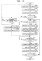
- FIG. 2 is a flowchart of the example of the process operations of the terminal according to the first embodiment. Especially, in the flowchart of FIG. 2 , the process operations of the detector 12, the calculator 13, and the process controller 14 are illustrated.
- An overall process operation of the terminal 10 includes processes of the touch panel 11 and process executer 15 before and after the process operations illustrated in the flowchart of FIG. 2 .
- the detector 12 acquires the amounts of changes in capacitance of the grids of the touch panel 11 (in step S101). For example, the detector 12 acquires the amounts of changes in capacitance at the first time and the amounts of changes in capacitance at the second time.
- the detector 12 detects touched regions based on the amounts, acquired in step S101, of the changes in the capacitance (in step S102).
- the detector 12 uses the amounts of the changes in the capacitance at the first time and the amounts of the changes in the capacitance at the second time to detect the first touched region at the first time and the second touched region at the second time.
- the calculator 13 approximates the touched regions detected by the detector 12 to ellipses (in step S103). For example, the calculator 13 approximates the aforementioned first and second touched regions to the ellipses.
- FIGs. 3 and 4 are diagrams describing an example of the elliptical approximation method.
- FIG. 3 illustrates a state in which the touch panel 11 is touched by the finger pad.
- hatched grids are grids in which the amounts of changes in capacitance are equal to or larger than the first threshold.
- a group of the hatched grids corresponds to a touched region.
- the detector 12 detects the group (or a group of grids hatched by diagonal lines and a group of grids hatched by a mesh-like pattern) of the hatched grids as the touched region.
- the calculator 13 determines whether or not the number of grids (or touched region grids) included in a touched region located adjacent to each of the touched regions to be subjected to the elliptical approximation is 2 or less.
- the calculator 13 identifies grids or edge grids that are included in a touched region located adjacent to each of the touched regions to be subjected to the elliptical approximation and of which the number is determined to be 2 or less.
- grids hatched by a mesh-like pattern are edge grids.
- the calculator 13 uses coordinates of the plurality of identified edge grids to approximate the touched regions to the ellipses.
- the calculator 13 uses the following Equation (1) to calculate the approximated ellipses.
- a B C D E ⁇ X i 2 ⁇ Y i 2 ⁇ X i ⁇ Y i 3 ⁇ X i 2 ⁇ Y i ⁇ X i ⁇ Y i 2 ⁇ X i ⁇ Y i ⁇ X i ⁇ Y i 3 ⁇ Y i 4 ⁇ X i ⁇ Y i 2 ⁇ Y i 3 ⁇ Y i 2 ⁇ X i 2 ⁇ Y i ⁇ X i ⁇ Y i 2 ⁇ X i 2 ⁇ X i ⁇ Y i ⁇ X i 2 ⁇ X i ⁇ Y i 2 ⁇ Y i 3 ⁇ X i ⁇ Y i ⁇ Y i ⁇ Y i 2 ⁇ Y i ⁇ X i ⁇ Y i 2 ⁇ Y i 3 ⁇ X i ⁇ Y i ⁇
- Equation (1) (X i , Y i ) represents coordinates of the edge grids.
- A, B, C, D, and E are coefficients used when the ellipses are expressed by the following Equation (2).
- the calculator 13 calculates angles formed between the major axes of the approximated ellipses and the reference axis of the touch panel 11 and calculates the centers of gravity of the approximated ellipses (in step S104). For example, the calculator 13 calculates the angles and the centers of gravity from the ellipses obtained by approximating the aforementioned first touched region and the aforementioned second touched region.
- FIG. 5 is a diagram describing the calculation of the angles and the centers of gravity.
- the major axis of an approximated ellipse E11 is represented by L11.
- the reference axis of the touch panel 11 is represented by A0.
- the calculator 13 uses the following Equation (3) to calculate an angle ⁇ formed between the major axis L11 and the reference axis A0, for example.
- the calculator 13 uses the following Equation (4) to calculate coordinates of the center of gravity of the ellipse E11, for example.
- Equation (4) X 0 represents an X coordinate of the center of gravity, and Y 0 represents a Y coordinate of the center of gravity.
- the process controller 14 controls the predetermined process based on a temporal change in the angle calculated by the calculator 13 and a temporal change in the center, calculated by the calculator 13, of gravity (in step S105).
- the calculator 13 controls the predetermined process based on the changes in the second angle and second reference point calculated by the calculator 13 from the second touched region with respect to the first angle and first reference point calculated by the calculator 13 from the first touched region.
- the process controller 14 executes the control to enlarge or reduce, at the rate corresponding to the difference between the first angle and the second angle, the image displayed on the touch panel 11.
- the aforementioned process is the display control of the touch panel 11.
- FIGs. 6 , 7 , and 8 are diagrams describing the process control if the predetermined process is the display control of the touch panel.
- the displayed image is reduced. Specifically, when the finger is moved toward a direction where the angle ⁇ is reduced, the displayed image is reduced.
- the calculator 13 approximates the first touched region detected by the detector 12 at the first time and the second touched region detected by the detector 12 at the second time to the ellipses. Then, the calculator 13 calculates the angles formed between the major axes of the approximated ellipses and the reference axis of the touch panel 11 and calculates the reference points of the ellipses. Then, the process controller 14 controls the predetermined process based on the changes in the second angle and second reference point calculated by the calculator 13 from the second touched region with respect to the first angle and first reference point calculated by the calculator 13 from the first touched region.
- the touch panel 11 is touched by a finger pad of a user and operated, and an operation by arc movement of the finger pad may be treated as a single process execution instruction operation. Since this movement is accomplished by one hand, it is possible to increase the number of types of process execution instruction operations that are easily performed with one hand and to improve the usability.
- the process controller 14 executes the control to enlarge or reduce, at the rate corresponding to the difference between the first angle and the second angle, the image displayed on the touch panel.
- operations of enlarging and reducing a displayed image which are achieved by the "pinch-in operation” and the “pinch-out operation” that are difficult to be executed by one hand, may be achieved by the process execution instruction operations that are easily performed with one hand.
- a second embodiment takes into account both operation by touching the touch panel with a finger pad and operation by touching the touch panel with a fingertip.
- FIG. 9 is a block diagram illustrating an example of a terminal according to the second embodiment.
- a terminal 50 includes an area calculator 51, a touch determining unit 52, a calculator 53, a process controller 54, and a process executer 55.
- the area calculator 51 calculates (counts) the area of a touched region detected by the detector 12 or the number of grids included in the touched region, for example.
- the area of the detected touched region may be 0. In this case, the area calculator 51 may determine that the touch panel 11 is not touched.
- the touch determining unit 52 determines, based on the area, calculated by the area calculator 51, of the touched region, whether a touch state of the touch panel 11 is a state in which "a large region is touched", a state in which "a small region is touched", or an "untouched state". For example, if the area, calculated by the area calculator 51, of the touched region is larger than a first determination threshold, the touch determining unit 52 determines that the touch panel 11 is in the state in which "the large region is touched”. If the area, calculated by the area calculator 51, of the touched region is equal to or smaller than the first determination threshold and larger than a second determination threshold, the touch determining unit 52 determines that the touch panel 11 is in the state in which "the small region is touched". In addition, if the area, calculated by the area calculator 51, of the touched region is equal to or smaller than the second determination threshold, the touch determining unit 52 determines that the touch panel 11 is in the "untouched state".
- the calculator 53 calculates a parameter corresponding to a touched state determined by the touch determining unit 52. For example, if the touch determining unit 52 determines that the touch panel 11 is in the state in which "the large region is touched", the calculator 53 approximates the touched region to an ellipse in the same manner as the first embodiment and calculates, as a parameter for the touched large region, an angle formed between the major axis of the approximated ellipse and the reference axis of the touch panel 11 and a reference point of the approximated ellipse. The calculated parameter is output to the process controller 54.
- the calculator 53 calculates, as a parameter for the touched small region, coordinates of the position of the touched region (for example, coordinates of the center of gravity of the touched region). The calculated parameter is output to the process controller 54. If the touch determining unit 52 determines that the touch panel 11 is in the "untouched state”, the calculator 53 does not calculate a parameter.
- the process controller 54 executes control based on a parameter received from the calculator 53. For example, when receiving the parameter for the touched large region, the process controller 54 controls the predetermined process based on the changes in the second angle and second reference point calculated by the calculator 13 from the second touched region with respect to the first angle and first reference point calculated by the calculator 13 from the first touched region in the same manner as the first embodiment.
- the process controller 54 execute control for the touched small region.
- the process controller 54 uses the coordinates of the position of the touched region to control a dragging process or control a process of selecting an icon.
- the process executer 54 executes a process in accordance with the control executed by the process controller 54.
- FIGs. 10 and 11 are flowcharts of the examples of the process operations of the terminal according to the second embodiment.
- process operations of the detector 12, the area calculator 51, the touch determining unit 52, and the calculator 53 are illustrated.
- process operations of the process controller 54 are illustrated.
- the detector 12 acquires the amounts of changes in the capacitance of the grids on the touch panel 11 (in step S201).
- the detector 12 detects a touched region based on the amounts, acquired in step S201, of the changes in the capacitance (in step S202).
- the area calculator 51 calculates the area of the touched region detected by the detector 12 (in step S203).
- the touch determining unit 52 determines, based on the area calculated by the area calculator 51, whether or not the touch panel 11 is touched (in step S204).
- step S204 If the touch determining unit 52 determines that the touch panel 11 is not touched (No in step S204), the detector 12 waits until a predetermined time elapses after the time of the previous acquisition (No in step S205). If the predetermined time has elapsed after the time of the previous acquisition (Yes in step S205), the detector 12 executes the process of step S201.
- step S204 the touch determining unit 52 determines whether or not the touch panel 11 is in the state in which a large region is touched or whether the touch panel 11 is in the state in which the large region is touched or in the state in which a small region is touched (in step S206).
- step S206 If the touch determining unit 52 determines that the touch panel 11 is in the state in which the large region is touched (Yes in step S206), the calculator 53 approximates the touched region to an ellipse (in step S207) and calculates an angle formed between the major axis of the approximated ellipse and the reference axis of the touch panel 11 and the center of gravity of the approximated ellipse (in step S208).
- the calculator 53 outputs information of the calculated angle and the calculated center of gravity to the process controller 54 (in step S209).
- the detector 12 waits until the predetermined time elapses after the time of the previous acquisition (No in step S210). If the predetermined time has elapsed after the time of the previous acquisition (Yes in step S210), the detector 12 acquires the amounts of changes in the capacitance of the grids of the touch panel 11 (in step S211).
- the detector 12 detects a touched region based on the amounts of the changes in the capacitance of the grids of the touch panel 11 (in step S212).
- the area calculator 51 calculates the area of the touched region detected by the detector 12 (in step S213).
- the touch determining unit 52 determines, based on the area calculated by the area calculator 51, whether or not the touch panel 11 is touched (in step S214).
- step S214 If the touch determining unit 52 determines that the touch panel 11 is not touched (No in step S214) or that the touched state is released, the process flow illustrated in FIG. 10 is terminated.
- step S214 If the touch determining unit 52 determines that the touch panel 11 is touched (Yes in step S214), the process flow returns to step S206.
- step S206 If the touch determining unit 52 determines that the touch panel 11 is in the state in which a small region is touched (No in step S206), the calculator 51 calculates coordinates of the touched region or point (in step S215) and outputs information of the calculated coordinates to the process controller 54 (in step S216).
- the process controller 54 waits for a parameter output from the calculator 53 (No in step S301).
- the process controller 54 determines whether or not the acquired parameter includes information of an angle (in step S302). Specifically, the process controller 54 determines whether or not the acquired parameter is a parameter for a touched large region or a parameter for a touched small region.
- the process controller 54 stores the acquired information of the angle and the center of gravity in a memory (not illustrated) (in step S303).
- the process controller 54 determines whether or not previously acquired information of an angle and the center of gravity or a previously acquired parameter for a touched large region has been stored in the aforementioned memory (in step S304).
- the process controller 54 determines that the previously acquired parameter for the touched large region has been stored (Yes in step S304)
- the process controller 54 controls the predetermined process based on temporal changes of the newly stored angle and center of gravity from the previously stored angle and center of gravity (in step S305).
- the previously stored angle and the previously stored center of gravity correspond to the second angle and the second center of gravity in the first embodiment.
- the newly stored angle and the newly stored center of gravity correspond to the first angle and the first center of gravity in the first embodiment.
- the process controller 54 determines whether or not a predetermined time has elapsed after the time of the previous acquisition of the parameter (in step S306).
- step S306 If the process controller 54 determines that the predetermined time has elapsed after the time of the previous acquisition of the parameter (Yes in step S306) or the touched state is released, the process flow illustrated in FIG. 11 is terminated.
- step S306 If the process controller 54 determines that the predetermined time has yet to elapse after the time of the previous acquisition of the parameter (No in step S306), the process flow returns to step S301. If the process controller 54 determines that the previously acquired parameter for the touched large region is not stored (No in step S304), the process flow returns to step S301.
- step S302 If the acquired parameter does not include the information of the angle (No in step S302) or the acquired parameter is the parameter for the touched small region, the process controller 54 uses the acquired coordinates of the touched point to control a process for the touched small region (in step S307). Then, the process flow proceeds to step S306.
- the touch panel 11 is operated by a process execution instruction operation upon the touch of a small region and is touched by a finger pad of a user and operated, and an operation by arc movement of the finger pad may be treated as a single process execution instruction operation. Since this movement is accomplished by one hand, it is possible to increase the number of types of process execution instruction operations that are easily performed with one hand and to improve the usability.
- all or a part of the various process functions to be executed by the terminals may be executed on a central processing unit (CPU) (or a microcomputer such as an micro processing unit (MPU) or an micro controller unit (MCU)).
- CPU central processing unit
- MPU micro processing unit
- MCU micro controller unit
- all or a part of the process functions may be executed on a program analyzed and executed by the CPU (or the microcomputer such as the MPU or the MCU) or on hardware by wired logic.
- the terminals according to the first and second embodiments may be achieved by the following hardware configuration.
- FIG. 12 is a diagram illustrating an example of hardware configurations of the terminals.
- a terminal 100 includes a touch panel 101, an integrated circuit (IC) 102, a processor 103, and a memory 104.
- the processor 103 are a CPU, a DSP, and an field programmable gate array (FPGA).
- the memory 104 are a random access memory (RAM) such as an synchronous dynamic random access memory (SDRAM), a read only memory (ROM), and a flash memory.
- RAM random access memory
- SDRAM synchronous dynamic random access memory
- ROM read only memory
- flash memory a flash memory
- the detector 12, calculators 13, 53, area calculator 51, and touch determining unit 52 of the terminals according to the first and second embodiments may be achieved by the IC 102.
- programs that correspond to the processes to be executed by the process controllers 14, 54 and the process executers 15, 55 are stored in the memory 104 and executed by the processor 103.
- the detector 12, the calculators 13, 53, the area calculator 51, the touch determining unit 52, and the process controllers 14, 54 may be achieved by the IC 102.
- programs that correspond to the processes to be executed by the process executers 15, 55 may be stored in the memory 104 and executed by the processor 103.
- the touch panel 11 may be achieved by the touch panel 101.
- programs that correspond to the processes to be executed by the detector 12, the calculators 13, 53, the process controllers 14, 54, the process executers 15, 55, the area calculator 51, and the touch determining unit 52 may be stored in the memory 104 and executed by the processor 103.
Landscapes
- Engineering & Computer Science (AREA)
- General Engineering & Computer Science (AREA)
- Theoretical Computer Science (AREA)
- Human Computer Interaction (AREA)
- Physics & Mathematics (AREA)
- General Physics & Mathematics (AREA)
- User Interface Of Digital Computer (AREA)
- Position Input By Displaying (AREA)
Applications Claiming Priority (1)
| Application Number | Priority Date | Filing Date | Title |
|---|---|---|---|
| JP2014039835A JP6442755B2 (ja) | 2014-02-28 | 2014-02-28 | 電子機器、制御プログラム、及び、制御方法 |
Publications (1)
| Publication Number | Publication Date |
|---|---|
| EP2913745A1 true EP2913745A1 (de) | 2015-09-02 |
Family
ID=52396512
Family Applications (1)
| Application Number | Title | Priority Date | Filing Date |
|---|---|---|---|
| EP15152103.6A Withdrawn EP2913745A1 (de) | 2014-02-28 | 2015-01-22 | Elektronische Vorrichtung, Steuerungsverfahren und integrierte Schaltung zur Charakterisierung von Berührungsflächen mittels Ellipsen |
Country Status (3)
| Country | Link |
|---|---|
| US (1) | US9857898B2 (de) |
| EP (1) | EP2913745A1 (de) |
| JP (1) | JP6442755B2 (de) |
Families Citing this family (3)
| Publication number | Priority date | Publication date | Assignee | Title |
|---|---|---|---|---|
| JP6442755B2 (ja) * | 2014-02-28 | 2018-12-26 | 富士通コネクテッドテクノロジーズ株式会社 | 電子機器、制御プログラム、及び、制御方法 |
| CN105117063A (zh) * | 2015-08-31 | 2015-12-02 | 联想(北京)有限公司 | 一种信息处理方法及电子设备 |
| JP6418299B1 (ja) * | 2017-09-15 | 2018-11-07 | 株式会社セガゲームス | 情報処理装置及びプログラム |
Citations (6)
| Publication number | Priority date | Publication date | Assignee | Title |
|---|---|---|---|---|
| JP2002501271A (ja) | 1998-01-26 | 2002-01-15 | ウェスターマン,ウェイン | 手操作入力を統合する方法および装置 |
| US20090300554A1 (en) * | 2008-06-03 | 2009-12-03 | Nokia Corporation | Gesture Recognition for Display Zoom Feature |
| US20120030624A1 (en) * | 2010-07-30 | 2012-02-02 | Migos Charles J | Device, Method, and Graphical User Interface for Displaying Menus |
| JP2012108674A (ja) | 2010-11-16 | 2012-06-07 | Ntt Docomo Inc | 表示端末 |
| JP2012174250A (ja) | 2011-02-24 | 2012-09-10 | Kyocera Corp | 携帯電子機器、接触操作制御方法および接触操作制御プログラム |
| JP2013097798A (ja) | 2011-10-27 | 2013-05-20 | Samsung Electronics Co Ltd | タッチパネルを備える携帯端末機の入力判定装置及び方法 |
Family Cites Families (24)
| Publication number | Priority date | Publication date | Assignee | Title |
|---|---|---|---|---|
| JP2005018284A (ja) * | 2003-06-24 | 2005-01-20 | Sanyo Electric Co Ltd | 携帯型電子装置 |
| JP2006127486A (ja) * | 2004-09-29 | 2006-05-18 | Toshiba Corp | 入力装置、コンピュータ装置、情報処理方法及び情報処理プログラム |
| JP2006345209A (ja) * | 2005-06-08 | 2006-12-21 | Sony Corp | 入力装置、情報処理装置、情報処理方法、及びプログラム |
| JP2008146453A (ja) * | 2006-12-12 | 2008-06-26 | Sony Corp | 映像信号出力装置、操作入力処理方法 |
| EP2187291A4 (de) * | 2007-09-05 | 2012-06-13 | Panasonic Corp | Tragbares endgerät und anzeigesteuerverfahren |
| EP2212764B1 (de) | 2007-10-11 | 2017-06-14 | Microsoft Technology Licensing, LLC | Verfahren zur handflächenberührungsidentifikation in mehrfachberührungs-digitalisierungssystemen |
| US8345014B2 (en) | 2008-07-12 | 2013-01-01 | Lester F. Ludwig | Control of the operating system on a computing device via finger angle using a high dimensional touchpad (HDTP) touch user interface |
| JP4609543B2 (ja) * | 2008-07-25 | 2011-01-12 | ソニー株式会社 | 情報処理装置及び情報処理方法 |
| US8284170B2 (en) * | 2008-09-30 | 2012-10-09 | Apple Inc. | Touch screen device, method, and graphical user interface for moving on-screen objects without using a cursor |
| US9063614B2 (en) * | 2009-02-15 | 2015-06-23 | Neonode Inc. | Optical touch screens |
| JP5326802B2 (ja) * | 2009-05-19 | 2013-10-30 | ソニー株式会社 | 情報処理装置、画像拡大縮小方法及びそのプログラム |
| TW201128478A (en) | 2010-02-12 | 2011-08-16 | Novatek Microelectronics Corp | Touch sensing method and system using the same |
| JP2011175310A (ja) * | 2010-02-23 | 2011-09-08 | Panasonic Corp | 情報処理装置および情報処理システム |
| JP6021335B2 (ja) * | 2011-12-28 | 2016-11-09 | 任天堂株式会社 | 情報処理プログラム、情報処理装置、情報処理システム、および、情報処理方法 |
| EP3196752B1 (de) * | 2012-02-09 | 2020-05-06 | Sony Corporation | Kapazitive berührungstafelvorrichtung, entsprechendes berührungseingabeerkennungsverfahren und entsprechendes computerprogrammprodukt |
| KR20130102298A (ko) * | 2012-03-07 | 2013-09-17 | 주식회사 팬택 | 휴대용 단말기 및 휴대용 단말기의 디스플레이 제어 방법 |
| EP2650754A3 (de) * | 2012-03-15 | 2014-09-24 | Omron Corporation | Gestenerkennungsvorrichtung, Elektronische Vorrichtung, Gestenerkennungsverfahren, Steuerprogramm und Aufzeichnungsmedium |
| JP5944743B2 (ja) * | 2012-05-23 | 2016-07-05 | 京セラ株式会社 | 携帯端末、表示制御プログラムおよび表示制御方法 |
| US9304622B2 (en) * | 2012-06-29 | 2016-04-05 | Parade Technologies, Ltd. | Touch orientation calculation |
| JP6024250B2 (ja) * | 2012-07-12 | 2016-11-09 | 富士通株式会社 | 補正装置、補正プログラム、及び補正方法 |
| JP5793625B2 (ja) * | 2012-09-29 | 2015-10-14 | ▲華▼▲為▼終端有限公司Huawei Device Co., Ltd. | ズーム処理を制御する方法及び電子装置 |
| KR101452053B1 (ko) * | 2012-11-26 | 2014-10-22 | 삼성전기주식회사 | 터치스크린 장치 및 터치스크린 장치의 화면 주밍 방법 |
| JP2015138379A (ja) * | 2014-01-22 | 2015-07-30 | 日産自動車株式会社 | 入力装置及び入力方法 |
| JP6442755B2 (ja) * | 2014-02-28 | 2018-12-26 | 富士通コネクテッドテクノロジーズ株式会社 | 電子機器、制御プログラム、及び、制御方法 |
-
2014
- 2014-02-28 JP JP2014039835A patent/JP6442755B2/ja active Active
-
2015
- 2015-01-22 EP EP15152103.6A patent/EP2913745A1/de not_active Withdrawn
- 2015-02-02 US US14/612,008 patent/US9857898B2/en active Active
Patent Citations (7)
| Publication number | Priority date | Publication date | Assignee | Title |
|---|---|---|---|---|
| JP2002501271A (ja) | 1998-01-26 | 2002-01-15 | ウェスターマン,ウェイン | 手操作入力を統合する方法および装置 |
| US7812828B2 (en) * | 1998-01-26 | 2010-10-12 | Apple Inc. | Ellipse fitting for multi-touch surfaces |
| US20090300554A1 (en) * | 2008-06-03 | 2009-12-03 | Nokia Corporation | Gesture Recognition for Display Zoom Feature |
| US20120030624A1 (en) * | 2010-07-30 | 2012-02-02 | Migos Charles J | Device, Method, and Graphical User Interface for Displaying Menus |
| JP2012108674A (ja) | 2010-11-16 | 2012-06-07 | Ntt Docomo Inc | 表示端末 |
| JP2012174250A (ja) | 2011-02-24 | 2012-09-10 | Kyocera Corp | 携帯電子機器、接触操作制御方法および接触操作制御プログラム |
| JP2013097798A (ja) | 2011-10-27 | 2013-05-20 | Samsung Electronics Co Ltd | タッチパネルを備える携帯端末機の入力判定装置及び方法 |
Also Published As
| Publication number | Publication date |
|---|---|
| JP2015165341A (ja) | 2015-09-17 |
| JP6442755B2 (ja) | 2018-12-26 |
| US9857898B2 (en) | 2018-01-02 |
| US20150248187A1 (en) | 2015-09-03 |
Similar Documents
| Publication | Publication Date | Title |
|---|---|---|
| US10324613B2 (en) | Method and electronic device for moving icon to page | |
| EP2713247B1 (de) | Verarbeitungsverfahren für berührungsoperationen und endgerät | |
| US20190073104A1 (en) | Display control method and device for side sliding interface, terminal and storage medium | |
| KR20120114163A (ko) | 정보 처리 장치, 정보 처리 방법 및 컴퓨터 판독가능 저장 매체 | |
| US20160349983A1 (en) | Terminal screen shot method and terminal | |
| CN105528130B (zh) | 一种控制方法、装置和电子设备 | |
| KR101372122B1 (ko) | 터치스크린에서의 벡터 기반 제스처를 보정하는 방법 및 그 장치 | |
| JP2013525891A (ja) | ユーザのタッチジェスチャを判別する方法及びデバイス | |
| US20150286283A1 (en) | Method, system, mobile terminal, and storage medium for processing sliding event | |
| EP2913745A1 (de) | Elektronische Vorrichtung, Steuerungsverfahren und integrierte Schaltung zur Charakterisierung von Berührungsflächen mittels Ellipsen | |
| CN104536643A (zh) | 一种图标拖动方法及终端 | |
| JP2016515276A5 (de) | ||
| KR20150091365A (ko) | 멀티터치 심볼 인식 | |
| CN105511789A (zh) | 一种图标处理方法以及终端 | |
| JP2017506399A (ja) | 改善されたタッチスクリーン精度のためのシステムおよび方法 | |
| US9904419B2 (en) | Capacitive sensor action in response to proximity sensor data | |
| JP2016531356A (ja) | ウィジェットエリアの調整方法および調整装置 | |
| JP7225516B2 (ja) | データ検出方法および装置、記憶媒体、タッチ装置 | |
| EP2843526A2 (de) | Fenstererweiterungsverfahren und entsprechende elektronische Vorrichtung | |
| US9823890B1 (en) | Modifiable bezel for media device | |
| CN104978135A (zh) | 一种图标显示方法、装置及移动终端 | |
| WO2014075540A1 (zh) | 触摸屏滚屏控制系统及方法 | |
| KR20160028224A (ko) | 터치 제스쳐에 기반하여 화면 분할 방법 및 장치 | |
| EP3051401B1 (de) | Bildanzeigevorrichtung, bildvergrösserungsverfahren und bildvergrösserungsprogramm | |
| JP5812582B2 (ja) | 情報処理装置および情報処理方法 |
Legal Events
| Date | Code | Title | Description |
|---|---|---|---|
| PUAI | Public reference made under article 153(3) epc to a published international application that has entered the european phase |
Free format text: ORIGINAL CODE: 0009012 |
|
| AK | Designated contracting states |
Kind code of ref document: A1 Designated state(s): AL AT BE BG CH CY CZ DE DK EE ES FI FR GB GR HR HU IE IS IT LI LT LU LV MC MK MT NL NO PL PT RO RS SE SI SK SM TR |
|
| AX | Request for extension of the european patent |
Extension state: BA ME |
|
| 17P | Request for examination filed |
Effective date: 20150819 |
|
| RBV | Designated contracting states (corrected) |
Designated state(s): AL AT BE BG CH CY CZ DE DK EE ES FI FR GB GR HR HU IE IS IT LI LT LU LV MC MK MT NL NO PL PT RO RS SE SI SK SM TR |
|
| 17Q | First examination report despatched |
Effective date: 20160308 |
|
| STAA | Information on the status of an ep patent application or granted ep patent |
Free format text: STATUS: THE APPLICATION HAS BEEN WITHDRAWN |
|
| 18W | Application withdrawn |
Effective date: 20180522 |