EP2913563A1 - Hybrid drive unit - Google Patents
Hybrid drive unit Download PDFInfo
- Publication number
- EP2913563A1 EP2913563A1 EP15154277.6A EP15154277A EP2913563A1 EP 2913563 A1 EP2913563 A1 EP 2913563A1 EP 15154277 A EP15154277 A EP 15154277A EP 2913563 A1 EP2913563 A1 EP 2913563A1
- Authority
- EP
- European Patent Office
- Prior art keywords
- combustion engine
- internal combustion
- electric motor
- neutral position
- gearbox
- Prior art date
- Legal status (The legal status is an assumption and is not a legal conclusion. Google has not performed a legal analysis and makes no representation as to the accuracy of the status listed.)
- Granted
Links
Images


Classifications
-
- F—MECHANICAL ENGINEERING; LIGHTING; HEATING; WEAPONS; BLASTING
- F16—ENGINEERING ELEMENTS AND UNITS; GENERAL MEASURES FOR PRODUCING AND MAINTAINING EFFECTIVE FUNCTIONING OF MACHINES OR INSTALLATIONS; THERMAL INSULATION IN GENERAL
- F16H—GEARING
- F16H61/00—Control functions within control units of change-speed- or reversing-gearings for conveying rotary motion ; Control of exclusively fluid gearing, friction gearing, gearings with endless flexible members or other particular types of gearing
- F16H61/22—Locking of the control input devices
-
- B—PERFORMING OPERATIONS; TRANSPORTING
- B60—VEHICLES IN GENERAL
- B60K—ARRANGEMENT OR MOUNTING OF PROPULSION UNITS OR OF TRANSMISSIONS IN VEHICLES; ARRANGEMENT OR MOUNTING OF PLURAL DIVERSE PRIME-MOVERS IN VEHICLES; AUXILIARY DRIVES FOR VEHICLES; INSTRUMENTATION OR DASHBOARDS FOR VEHICLES; ARRANGEMENTS IN CONNECTION WITH COOLING, AIR INTAKE, GAS EXHAUST OR FUEL SUPPLY OF PROPULSION UNITS IN VEHICLES
- B60K6/00—Arrangement or mounting of plural diverse prime-movers for mutual or common propulsion, e.g. hybrid propulsion systems comprising electric motors and internal combustion engines ; Control systems therefor, i.e. systems controlling two or more prime movers, or controlling one of these prime movers and any of the transmission, drive or drive units Informative references: mechanical gearings with secondary electric drive F16H3/72; arrangements for handling mechanical energy structurally associated with the dynamo-electric machine H02K7/00; machines comprising structurally interrelated motor and generator parts H02K51/00; dynamo-electric machines not otherwise provided for in H02K see H02K99/00
- B60K6/20—Arrangement or mounting of plural diverse prime-movers for mutual or common propulsion, e.g. hybrid propulsion systems comprising electric motors and internal combustion engines ; Control systems therefor, i.e. systems controlling two or more prime movers, or controlling one of these prime movers and any of the transmission, drive or drive units Informative references: mechanical gearings with secondary electric drive F16H3/72; arrangements for handling mechanical energy structurally associated with the dynamo-electric machine H02K7/00; machines comprising structurally interrelated motor and generator parts H02K51/00; dynamo-electric machines not otherwise provided for in H02K see H02K99/00 the prime-movers consisting of electric motors and internal combustion engines, e.g. HEVs
- B60K6/42—Arrangement or mounting of plural diverse prime-movers for mutual or common propulsion, e.g. hybrid propulsion systems comprising electric motors and internal combustion engines ; Control systems therefor, i.e. systems controlling two or more prime movers, or controlling one of these prime movers and any of the transmission, drive or drive units Informative references: mechanical gearings with secondary electric drive F16H3/72; arrangements for handling mechanical energy structurally associated with the dynamo-electric machine H02K7/00; machines comprising structurally interrelated motor and generator parts H02K51/00; dynamo-electric machines not otherwise provided for in H02K see H02K99/00 the prime-movers consisting of electric motors and internal combustion engines, e.g. HEVs characterised by the architecture of the hybrid electric vehicle
- B60K6/48—Parallel type
-
- B—PERFORMING OPERATIONS; TRANSPORTING
- B60—VEHICLES IN GENERAL
- B60K—ARRANGEMENT OR MOUNTING OF PROPULSION UNITS OR OF TRANSMISSIONS IN VEHICLES; ARRANGEMENT OR MOUNTING OF PLURAL DIVERSE PRIME-MOVERS IN VEHICLES; AUXILIARY DRIVES FOR VEHICLES; INSTRUMENTATION OR DASHBOARDS FOR VEHICLES; ARRANGEMENTS IN CONNECTION WITH COOLING, AIR INTAKE, GAS EXHAUST OR FUEL SUPPLY OF PROPULSION UNITS IN VEHICLES
- B60K6/00—Arrangement or mounting of plural diverse prime-movers for mutual or common propulsion, e.g. hybrid propulsion systems comprising electric motors and internal combustion engines ; Control systems therefor, i.e. systems controlling two or more prime movers, or controlling one of these prime movers and any of the transmission, drive or drive units Informative references: mechanical gearings with secondary electric drive F16H3/72; arrangements for handling mechanical energy structurally associated with the dynamo-electric machine H02K7/00; machines comprising structurally interrelated motor and generator parts H02K51/00; dynamo-electric machines not otherwise provided for in H02K see H02K99/00
- B60K6/20—Arrangement or mounting of plural diverse prime-movers for mutual or common propulsion, e.g. hybrid propulsion systems comprising electric motors and internal combustion engines ; Control systems therefor, i.e. systems controlling two or more prime movers, or controlling one of these prime movers and any of the transmission, drive or drive units Informative references: mechanical gearings with secondary electric drive F16H3/72; arrangements for handling mechanical energy structurally associated with the dynamo-electric machine H02K7/00; machines comprising structurally interrelated motor and generator parts H02K51/00; dynamo-electric machines not otherwise provided for in H02K see H02K99/00 the prime-movers consisting of electric motors and internal combustion engines, e.g. HEVs
- B60K6/50—Architecture of the driveline characterised by arrangement or kind of transmission units
- B60K6/54—Transmission for changing ratio
- B60K6/547—Transmission for changing ratio the transmission being a stepped gearing
-
- B—PERFORMING OPERATIONS; TRANSPORTING
- B60—VEHICLES IN GENERAL
- B60W—CONJOINT CONTROL OF VEHICLE SUB-UNITS OF DIFFERENT TYPE OR DIFFERENT FUNCTION; CONTROL SYSTEMS SPECIALLY ADAPTED FOR HYBRID VEHICLES; ROAD VEHICLE DRIVE CONTROL SYSTEMS FOR PURPOSES NOT RELATED TO THE CONTROL OF A PARTICULAR SUB-UNIT
- B60W20/00—Control systems specially adapted for hybrid vehicles
-
- B—PERFORMING OPERATIONS; TRANSPORTING
- B60—VEHICLES IN GENERAL
- B60W—CONJOINT CONTROL OF VEHICLE SUB-UNITS OF DIFFERENT TYPE OR DIFFERENT FUNCTION; CONTROL SYSTEMS SPECIALLY ADAPTED FOR HYBRID VEHICLES; ROAD VEHICLE DRIVE CONTROL SYSTEMS FOR PURPOSES NOT RELATED TO THE CONTROL OF A PARTICULAR SUB-UNIT
- B60W50/00—Details of control systems for road vehicle drive control not related to the control of a particular sub-unit, e.g. process diagnostic or vehicle driver interfaces
- B60W50/08—Interaction between the driver and the control system
- B60W50/082—Selecting or switching between different modes of propelling
-
- F—MECHANICAL ENGINEERING; LIGHTING; HEATING; WEAPONS; BLASTING
- F16—ENGINEERING ELEMENTS AND UNITS; GENERAL MEASURES FOR PRODUCING AND MAINTAINING EFFECTIVE FUNCTIONING OF MACHINES OR INSTALLATIONS; THERMAL INSULATION IN GENERAL
- F16H—GEARING
- F16H59/00—Control inputs to control units of change-speed-, or reversing-gearings for conveying rotary motion
- F16H59/02—Selector apparatus
-
- B—PERFORMING OPERATIONS; TRANSPORTING
- B60—VEHICLES IN GENERAL
- B60K—ARRANGEMENT OR MOUNTING OF PROPULSION UNITS OR OF TRANSMISSIONS IN VEHICLES; ARRANGEMENT OR MOUNTING OF PLURAL DIVERSE PRIME-MOVERS IN VEHICLES; AUXILIARY DRIVES FOR VEHICLES; INSTRUMENTATION OR DASHBOARDS FOR VEHICLES; ARRANGEMENTS IN CONNECTION WITH COOLING, AIR INTAKE, GAS EXHAUST OR FUEL SUPPLY OF PROPULSION UNITS IN VEHICLES
- B60K6/00—Arrangement or mounting of plural diverse prime-movers for mutual or common propulsion, e.g. hybrid propulsion systems comprising electric motors and internal combustion engines ; Control systems therefor, i.e. systems controlling two or more prime movers, or controlling one of these prime movers and any of the transmission, drive or drive units Informative references: mechanical gearings with secondary electric drive F16H3/72; arrangements for handling mechanical energy structurally associated with the dynamo-electric machine H02K7/00; machines comprising structurally interrelated motor and generator parts H02K51/00; dynamo-electric machines not otherwise provided for in H02K see H02K99/00
- B60K6/20—Arrangement or mounting of plural diverse prime-movers for mutual or common propulsion, e.g. hybrid propulsion systems comprising electric motors and internal combustion engines ; Control systems therefor, i.e. systems controlling two or more prime movers, or controlling one of these prime movers and any of the transmission, drive or drive units Informative references: mechanical gearings with secondary electric drive F16H3/72; arrangements for handling mechanical energy structurally associated with the dynamo-electric machine H02K7/00; machines comprising structurally interrelated motor and generator parts H02K51/00; dynamo-electric machines not otherwise provided for in H02K see H02K99/00 the prime-movers consisting of electric motors and internal combustion engines, e.g. HEVs
- B60K6/42—Arrangement or mounting of plural diverse prime-movers for mutual or common propulsion, e.g. hybrid propulsion systems comprising electric motors and internal combustion engines ; Control systems therefor, i.e. systems controlling two or more prime movers, or controlling one of these prime movers and any of the transmission, drive or drive units Informative references: mechanical gearings with secondary electric drive F16H3/72; arrangements for handling mechanical energy structurally associated with the dynamo-electric machine H02K7/00; machines comprising structurally interrelated motor and generator parts H02K51/00; dynamo-electric machines not otherwise provided for in H02K see H02K99/00 the prime-movers consisting of electric motors and internal combustion engines, e.g. HEVs characterised by the architecture of the hybrid electric vehicle
- B60K6/48—Parallel type
- B60K2006/4808—Electric machine connected or connectable to gearbox output shaft
-
- B—PERFORMING OPERATIONS; TRANSPORTING
- B60—VEHICLES IN GENERAL
- B60W—CONJOINT CONTROL OF VEHICLE SUB-UNITS OF DIFFERENT TYPE OR DIFFERENT FUNCTION; CONTROL SYSTEMS SPECIALLY ADAPTED FOR HYBRID VEHICLES; ROAD VEHICLE DRIVE CONTROL SYSTEMS FOR PURPOSES NOT RELATED TO THE CONTROL OF A PARTICULAR SUB-UNIT
- B60W2540/00—Input parameters relating to occupants
- B60W2540/14—Clutch pedal position
-
- B—PERFORMING OPERATIONS; TRANSPORTING
- B60—VEHICLES IN GENERAL
- B60W—CONJOINT CONTROL OF VEHICLE SUB-UNITS OF DIFFERENT TYPE OR DIFFERENT FUNCTION; CONTROL SYSTEMS SPECIALLY ADAPTED FOR HYBRID VEHICLES; ROAD VEHICLE DRIVE CONTROL SYSTEMS FOR PURPOSES NOT RELATED TO THE CONTROL OF A PARTICULAR SUB-UNIT
- B60W2540/00—Input parameters relating to occupants
- B60W2540/16—Ratio selector position
-
- B—PERFORMING OPERATIONS; TRANSPORTING
- B60—VEHICLES IN GENERAL
- B60W—CONJOINT CONTROL OF VEHICLE SUB-UNITS OF DIFFERENT TYPE OR DIFFERENT FUNCTION; CONTROL SYSTEMS SPECIALLY ADAPTED FOR HYBRID VEHICLES; ROAD VEHICLE DRIVE CONTROL SYSTEMS FOR PURPOSES NOT RELATED TO THE CONTROL OF A PARTICULAR SUB-UNIT
- B60W2710/00—Output or target parameters relating to a particular sub-units
- B60W2710/06—Combustion engines, Gas turbines
- B60W2710/0644—Engine speed
-
- B—PERFORMING OPERATIONS; TRANSPORTING
- B60—VEHICLES IN GENERAL
- B60Y—INDEXING SCHEME RELATING TO ASPECTS CROSS-CUTTING VEHICLE TECHNOLOGY
- B60Y2200/00—Type of vehicle
- B60Y2200/90—Vehicles comprising electric prime movers
- B60Y2200/92—Hybrid vehicles
-
- F—MECHANICAL ENGINEERING; LIGHTING; HEATING; WEAPONS; BLASTING
- F16—ENGINEERING ELEMENTS AND UNITS; GENERAL MEASURES FOR PRODUCING AND MAINTAINING EFFECTIVE FUNCTIONING OF MACHINES OR INSTALLATIONS; THERMAL INSULATION IN GENERAL
- F16H—GEARING
- F16H59/00—Control inputs to control units of change-speed-, or reversing-gearings for conveying rotary motion
- F16H59/02—Selector apparatus
- F16H2059/0221—Selector apparatus for selecting modes, i.e. input device
-
- F—MECHANICAL ENGINEERING; LIGHTING; HEATING; WEAPONS; BLASTING
- F16—ENGINEERING ELEMENTS AND UNITS; GENERAL MEASURES FOR PRODUCING AND MAINTAINING EFFECTIVE FUNCTIONING OF MACHINES OR INSTALLATIONS; THERMAL INSULATION IN GENERAL
- F16H—GEARING
- F16H59/00—Control inputs to control units of change-speed-, or reversing-gearings for conveying rotary motion
- F16H59/68—Inputs being a function of gearing status
- F16H2059/6807—Status of gear-change operation, e.g. clutch fully engaged
-
- F—MECHANICAL ENGINEERING; LIGHTING; HEATING; WEAPONS; BLASTING
- F16—ENGINEERING ELEMENTS AND UNITS; GENERAL MEASURES FOR PRODUCING AND MAINTAINING EFFECTIVE FUNCTIONING OF MACHINES OR INSTALLATIONS; THERMAL INSULATION IN GENERAL
- F16H—GEARING
- F16H2312/00—Driving activities
- F16H2312/14—Going to, or coming from standby operation, e.g. for engine start-stop operation at traffic lights
-
- Y—GENERAL TAGGING OF NEW TECHNOLOGICAL DEVELOPMENTS; GENERAL TAGGING OF CROSS-SECTIONAL TECHNOLOGIES SPANNING OVER SEVERAL SECTIONS OF THE IPC; TECHNICAL SUBJECTS COVERED BY FORMER USPC CROSS-REFERENCE ART COLLECTIONS [XRACs] AND DIGESTS
- Y02—TECHNOLOGIES OR APPLICATIONS FOR MITIGATION OR ADAPTATION AGAINST CLIMATE CHANGE
- Y02T—CLIMATE CHANGE MITIGATION TECHNOLOGIES RELATED TO TRANSPORTATION
- Y02T10/00—Road transport of goods or passengers
- Y02T10/60—Other road transportation technologies with climate change mitigation effect
- Y02T10/62—Hybrid vehicles
Definitions
- the invention relates to a hybrid drive unit for a vehicle and to a method for operating a hybrid vehicle, that is to say a vehicle drivable by an internal combustion engine and by an electric motor.
- Vehicles with hybrid drive are in terms of their operation, in particular as regards the engagement of driving levels, usually comparable with purely internal combustion engine driven vehicles with automatic transmission. From the DE 10 2008 042 682 A1 For example, a hybrid vehicle drive system with planetary gear mechanisms is known.
- the DE 10 2007 052 261 A1 a so-called hybrid manual transmission.
- a selector member having a plurality of shift gates arranged in an H-shaped shift pattern is provided, which allows a manual change between different gear ratios of the transmission.
- the selection element enables the activation of an electric machine, which is used in the electric driving operation of the hybrid vehicle as the sole traction drive motor.
- the manually shiftable transmission of the hybrid vehicle is switched to its neutral position during the electric driving operation.
- To insert an electric reverse gear can after the DE 10 2007 052 261 A1 the operation of an additional lever must be required.
- the DE 10 2010 023 093 A1 discloses a powertrain for a motor vehicle, which comprises an internal combustion engine and an electric drive unit, wherein between the internal combustion engine and the axis of the motor vehicle driven by the internal combustion engine, a freewheel is arranged.
- the freewheel should serve to avoid drag torque due to the internal combustion engine in electromotive operation of the motor vehicle. Furthermore, it should be possible by the freewheel to start the engine during a purely electromotive operation of the motor vehicle, without directly affecting the electromotive operation.
- it is provided to first engage a gear stage of a gearbox coupled to the internal combustion engine. This is to ensure that the correct gear is engaged even in purely electric motor operation, so that a connection of the engine can be done quickly.
- the invention has for its object to further develop a hybrid drive unit over the cited prior art, in particular in terms of ease of use and the risks of incorrect conditions.
- the hybrid drive unit comprises a manually operable selection element, in particular in the form of a shift lever, which enables the change of gears of a gearbox on the one hand with internal combustion engine drive and on the other the activation of an electric motor provided as a drive motor.
- a manually operable selection element in particular in the form of a shift lever, which enables the change of gears of a gearbox on the one hand with internal combustion engine drive and on the other the activation of an electric motor provided as a drive motor.
- Two mutually distinguishable neutral positions of the selector corresponding respectively with the neutral position of the gearbox, from the first neutral position of the selector out, as in a conventional transmission, the gears of the gearbox are interchangeable and in the second neutral position of the selector element exclusively the electric motor is activated as a traction drive, while the internal combustion engine is at most for driving at least one auxiliary unit, for example a generator, in operation.
- electric motor in the singular does not exclude that a plurality of electric motors is provided as traction drive motors. For example, these may be wheel hub motors or motors near the wheel.
- the electric motor or the arrangement of a plurality of electric motors does not necessarily have a mechanical connection with the internal combustion engine. Accordingly, the manually operable selector element, which is attributable to the internal combustion engine powertrain, is not mechanically coupled to the electromotive powertrain in typical configurations. In any case, a locking mechanism is provided, which must be overcome or unlocked to move the selector element from the first neutral position to the second neutral position or vice versa.
- the locking mechanism can be realized in a variety of configurations and, for example, purely mechanical (eg only springs for detent) or electromechanical Include locking elements.
- the locking mechanism uses at least one component of the vehicle equipped with the hybrid drive unit vehicle, which is already present in a vehicle with manually operable manual transmission.
- at least one component of a manually operable clutch actuation mechanism in particular a sensor of this clutch actuation mechanism, is a functional element of the lock mechanism.
- pedaling of the clutch pedal of the hybrid vehicle may be required in this case.
- the locking mechanism may comprise an actuating element, for example in the form of a button, attached to the selection element, which is to be actuated in order to be able to move the selection element from one neutral position to the other neutral position.
- an actuating element for example in the form of a button, attached to the selection element, which is to be actuated in order to be able to move the selection element from one neutral position to the other neutral position.
- the locking mechanism is realized in the form of a defined detent position of the selection element or a component of the transmission, which can be overcome by force on the selector element.
- the selection element is preferably designed as a shift lever, which is switchable in a conventional H-shaped circuit diagram.
- H-shaped here are also schematics referred to, which are commonly referred to as “double-H” or “pitchfork”.
- the two neutral positions of the selection element are preferably arranged in one and the same lane of the circuit diagram.
- Advantageous are designs of the circuit diagram in which the position in which the electric drive mode is activated, is arranged near the lowest gears of the gearbox.
- the power flow between the engine and the drivable by these wheels of the vehicle is interrupted by the neutral position of the gearbox.
- defined by the state of the clutch, which is located in the internal combustion engine powertrain distinguishable states of the electric motor drive train, even if the internal combustion engine and the electric motor drive train are separated.
- a reduction of the output from the electric motor power can be provided to zero when the driver of the hybrid vehicle opens the clutch, that is - in the case of conventional control concepts - the clutch pedal occurs. In this way, the driver perceived as a natural driving feeling is generated, which is pronounced of a conventional, purely internal combustion engine driven vehicle with manual transmission.
- an overrunning clutch is integrated in the internal combustion engine drive train, as in principle from the DE 10 2010 023 093 A1 known. Due to the freewheel and the lack of drag torque of the internal combustion engine a particularly high recuperation is possible in the generator mode of the electric traction drive motor. In addition, the lack of drag torque of the internal combustion engine ensures a driving impression that reminds the driver of a conventional vehicle with automatic torque converter.
- the hybrid drive unit is preferably used in a vehicle such as passenger cars with a conventional non-automated transmission.
- the hybrid drive unit may also be integrated in vehicles with automated transmission, such as dual-clutch transmission, in which case the locking mechanism, which is to overcome when switching between internal combustion engine and electric motor drive, at least from the operator's point of view, no relation to the clutch operation Has.
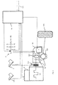
- FIGS. 1 to 6 illustrate various types of hybrid vehicle, in each of which the hybrid drive unit according to the invention and the operating method according to the invention is realized.
- an internal combustion engine 101 namely a diesel engine or a gasoline engine
- torque via a clutch 102 to a transmission 103.
- an accelerator pedal 106, a clutch pedal 7 as a component of a not fully shown clutch actuating mechanism, and a manual switching device 8 are indicated with a circuit diagram SC.
- the accelerator pedal 106 is associated with an engine control 9 in terms of control technology.
- the position of the clutch pedal 7, with which the clutch 2 can be actuated detectable by a suitable sensor system known per se.
- the engine control unit 9 is linked to a control unit 10, which has a central function within the hybrid vehicle, both in the case of an electric motor drive and an internal combustion engine drive.
- the control unit 10 processes various input signals ES such as, for example, the vehicle speed.
- the manual switchability of the gearbox 103 is influenced by the control unit 10, as will be explained in more detail below.
- the control unit 10 By the control unit 10, the energization of an electric motor 11 is determined, which drives the rear wheels 13 of the hybrid vehicle via a transmission 12. A switched between the transmission 12 and the rear wheels 13 differential gear is not shown in this case. Instead of a single electric motor 11, a separate electric motor for driving each rear wheel 13, for example in the form of a wheel hub motor, may be provided.
- the transmission 12 may be a fixed ratio transmission, a multiple discrete ratio, or a variable ratio transmission.
- the transmission 12 may also include an idle position or clutch.
- the embodiment according to Fig. 2 differs from the embodiment according to Fig. 1 in that, in addition to the internal combustion engine 101, the electric motor 11 also drives the front wheels 105.
- the electric motor 11 is in this case arranged together with the gearbox 103 and the differential gear 104 in a common housing 14 and has a motor shaft, not shown, which is rotatably connected to a transmission output shaft 15 of the gearbox 103.
- the embodiment according to Fig. 2 could be connected between the motor shaft of the electric motor 11 and the transmission output shaft 15 is a switchable, operable by means of the control unit 10 clutch.
- the embodiments of the Fig. 3 to 6 each show a vehicle with pure rear-wheel drive. While in the arrangements according to Fig. 3 and Fig. 4 the electric motor 11 is installed in the housing 14 in which the manual transmission 103 is installed, the electric motor 11 is in the in Fig. 5 and Fig. 6 sketched cases located near the designated 16 rear axle of the vehicle.
- Fig. 3 is the electric motor 11 - comparable to the solution after Fig. 2 - Coupled directly to the transmission output shaft 15.
- the motor shaft of the electric motor 11 according to Fig. 3 is further rotatably connected to a propeller shaft 17.
- the embodiment according to Fig. 4 differs from the embodiment according to Fig. 3 in that the electric motor 11 is not coupled as a direct drive motor to the propeller shaft 17, but via a gear stage 18 feeds torque into the cardan shaft 17.
- the electric motor 11 drives the cardan shaft 17 directly.
- the electric motor 11 may be arranged in a manner not shown together with the differential gear 104 in a common housing. While in the embodiment according to Fig. 5 the rotor of the electric motor 11 always rotates at the speed of the propeller shaft 17 is in the embodiment according to Fig. 6 17 is a switchable clutch 19 connected between the electric motor 11 and the propeller shaft. This allows an on-demand connection and disconnection of the electric motor 11, which as well as in the embodiments of the Fig. 1 to 5 , optionally as a drive motor or can be operated as a generator.
- the clutch 19 can in the embodiment according to Fig. 6 - in principle comparable to the solution according to Fig. 4 - A reduction gear between the electric motor 11 and the differential gear 104 may be connected.
- the Fig. 7 shows the circuit diagram SC of the manual switching device 8, as in each of the embodiments of the Fig. 1 to 6 is used, wherein in the Fig. 1 to 6 the lowest gear of the gearbox 103 is denoted by "2", since the starting preferably takes place electrically.
- N1 In the first neutral position N1 is the gearbox 103, as in a conventional, purely internal combustion engine driven vehicle with manual transmission, in the selector gate, from which the individual Forward gears 1 to 5 and the reverse gear R can be inserted.
- the purely electric motor drive mode referred to in the circuit diagram as e-gear E, is exclusively selectable from the second neutral position N2, wherein the positions N2 and E can coincide in the circuit diagram SC.
- a change between the neutral positions N1, N2 is only possible by overcoming a designated SP locking mechanism.
- the release of the locking mechanism SP is carried out by actuation of the clutch 2, that is by pressing the clutch pedal 7.
- the change between internal combustion engine and electric motor drive is thus comparable from the user's perspective with the change between different forward gears of the gearbox 103 or with the change between one of the forward gears 1 to 5 and the reverse gear R.
- the Fig. 8 shows various other switching schemes SC, which instead of the circuit diagram SC after Fig. 7 in the drive concepts after the Fig. 1 to 6 are usable.
- the reverse gear R can be realized by the internal combustion engine and / or electric motor drive train.
- the first two in the top row in Fig. 8 Schematics SC shown on the left are functionally identical and correspond to the schematics SC according to the Fig. 1 to 7 ,
- the locking mechanism SP as far as it is expressed in the circuit diagram SC, is in Fig. 8 each indicated by a triangle.
- the locking mechanism SP is realized by a system of hardware and software components.
- FIG. 9 Dashed line indicated shift diagram SC corresponds to the circuit diagram SC to Fig. 7 , Likewise, at this point any other circuit diagram SC could Fig. 8 to be found.
- a selector element 20, namely a shift lever, of the manual shifting device 8 is mounted by means of a joint 21 and sealed by a bellows 22 to a center console 23.
- the manual switching device 8 could for example be designed as a steering wheel circuit.
- a shift knob on the lever rod also called shift lever 20 is in Fig. 9 denoted by 24.
- the shift knob 24 facing away, located within the center console 23 or a tunnel end of the shift lever 20 can be brought into different positions, which describe an inverse, that is mirrored circuit diagram ISC, which in Fig. 9 is shown in dashed lines analogous to the circuit diagram SC.
- the position of the shift lever 20, through which a switching device 25 and a selector 26, in the embodiment according to FIG Fig. 9 each realized as a Bowden cable, can be actuated, can be detected by a sensor device 27.
- the switching and selection devices 25, 26 can also include, for example, rods, chains, hydraulic or electrical actuating mechanisms.
- the mobility of the shift lever 20 by a blocking element 28 can be limited, which is a mechanical component of the locking mechanism SP and operates with an electromagnet 29.
- the energization of the electromagnet 29 is determined by the control unit 10, which processes signals which indicate the operating state of the clutch 2.
- FIGS. 10 and 11 out Details of possible embodiments of the blocking element 28 go out of the FIGS. 10 and 11 out.
- a switching shaft 30 is visible, which is pivotable about its own axis or along its axis by means of the switching device 25 and selector 26.
- a shift finger 31 is connected, which cooperates with shift rails 32, which allow the insertion of the gears 1 to 6 of the gearbox 103.
- a locking device 33 is indicated, the locking forces generated in the switching and selection direction of the switching shaft 30.
- the locking device 33 has no electromechanical actuator.
- a designated 34 by means of the electromagnet 29 displaceable locking pin engages in the case of Fig.
- Fig. 12 illustrated in the bottom diagram.
- an e-gear signal EG supplied by the sensor device 27 is significant, eg maximum.
- the here maximum e-gear signal, which is supplied by the sensor device 27 in the position E of the shift lever 20 is denoted by EGm.
- the dashed line in Fig. 12 corresponds to the position designated SP ( Fig. 7 ) of the shift lever 20, that is the position over which the shift lever 20 can be pivoted away only when unlocked locking mechanism SP.
- Fig. 12 indicates to apply partially increased actuation forces FE, which are typically also apply to engage one of the higher gears of the gearbox 103.
- the opening of the clutch 102 in the course of switching between purely electric motor and internal combustion engine operation further effects, which are realized by means of the control unit 10 and motor control 9.
- the control unit 10 and motor control 9 For example, when the electric gear is engaged, as soon as the clutch pedal 7 is stepped on, the internal combustion engine 1 is started, provided that it is not already running and a certain speed threshold, for example 10 km / h, has been exceeded.
- a certain speed threshold for example 10 km / h
- the consideration of further criteria such as the state of charge of the battery or the engine temperature is advantageous. In this way, a very fast, fluid transition between the electric motor and the internal combustion engine drive is made possible. This transition is optionally facilitated by indicating to the driver which gear to engage.
- the engagement of the gear is automatically facilitated by bringing the speed of the internal combustion engine 101 to an appropriate level before engaging. If the driver engages in a too low gear, then the improper gear selection is indicated by a pronounced spin-up of the internal combustion engine. This gives the driver an intuitively understandable warning signal, which also includes a learning effect in case of repeated operating errors.
- Fig. 13 is a start-up and acceleration process of a vehicle is illustrated, which is used as a manual hybrid vehicle according to one of Fig. 1 to 6 is designed.
- the bottom diagram in Fig. 13 is the course of three speeds n, namely the wheel speed NR, the crankshaft speed NM, and the rotational speed NG of the transmission output shaft 15, as a function of the time t shown.
- the middle diagram in Fig. 13 shows two pedal positions PS, namely the gas pedal position GP of the accelerator pedal 106 and the clutch pedal position KS of the clutch pedal 7.
- various positions of the shift lever 20 also in dependence on the time t, indicated, in which case the multi-dimensional design of the circuit diagram SC is disregarded.
- the starting process begins purely electrically, with the shift lever 20 is in the "E" position.
- the clutch 102 is closed in this case.
- the engine 101 is automatically started.
- the shift lever 20 is in the same course on the neutral positions N1, N2, in Fig. 13 summarized as N, in a gear position, in Fig. 13 labeled G, brought.
- This procedure may differ from the simplified diagram Fig. 13 , Gas are taken away, that is, the accelerator pedal 106 are withdrawn in the direction 0, as is usually done in the operation of a manual transmission.
- the driver engages after engaging the gear G, wherein the further acceleration of the vehicle takes place either by the internal combustion engine 101 alone or both by the electric motor 11 and by the internal combustion engine 101.
- a full-throttle phase VP a short-term available increased power of the electric motor 11 is called up.
- the full-throttle phase VP is followed by a renewed, manual gear change, wherein the operation of the clutch pedal 7, the accelerator pedal 106, and the shift lever 20 takes place in accordance with the engagement of a gear G when starting the internal combustion engine 101.
- the vehicle is operated purely electrically in a first method step designated S1, wherein the electric gear is engaged.
- the accelerator pedal 106 which is also referred to as an accelerator pedal in particular in an electric vehicle, as well as a brake pedal, not shown in the figures, are coupled with the electric motor 11 such that it can be used not only as a traction drive motor but also for recuperation.
- the locking mechanism SP is activated in this case, whereby in particular unwanted connection of the internal combustion engine drive is prevented.
- step S2 the shift lever 20 is manually removed from the position E, as far as this is possible in terms of hardware in this state.
- the internal combustion engine 101 can be started automatically, whereby a significant gain in time is achieved when switching between electric motor and internal combustion engine drive.
- step S3 it is checked by means of the control unit 10 whether the locking mechanism SP is activated.
- locking mechanism in this case all components are subsumed that affect the switchability between the two neutral positions N1, N2, including control and software components.
- Locking mechanism SP which is synonymous with non-pedaled clutch pedal 7, is blocked in step S4, the change in the internal combustion engine operation.
- the second neutral position N2 that is to say the selector gate of the manual transmission 103, can be selected in step S5. If the internal combustion engine 101 has not yet been started when the electric gear is laid out, it is started at the latest in the second neutral position N2.
- the clutch 102 is closed without engaging a gear, it is optional - similar to a conventional start-stop system - a shutdown of the internal combustion engine 101 is provided, which may be dependent on parameters such as engine or outside temperature and battery state of charge , At the same time the locking mechanism SP is closed in this case, so that a renewed engagement of the E-gear would only be possible if the clutch pedal 7 stepped again and thus the locking mechanism SP would be disabled.
- the driver inserts one of the gears of the gearbox 103 after the change from the first neutral position N1 to the second neutral position N2 and then closes the clutch 102. This is done in the last method step S6, whereby the change into the internal combustion engine drive mode is completed.
- the lock mechanism SP is unlocked, that is, the changeover to the internal combustion engine drive mode is enabled.
- the internal combustion engine 101 remains in operation or the internal combustion engine 101 is started, if it is not yet in operation. If the internal combustion engine 101 is operated at idling speed, an automatic increase in the rotational speed of the internal combustion engine 101 can be triggered by stepping the clutch pedal 7, that is, the transition from the state Z11 to the state Z12.
- the state Z15 is given when one of the gears G of the gearbox 103 is engaged, in which state the clutch 102 can be closed to start combustion engine.
- energization of the electric motor 11 upon actuation of the accelerator pedal 106 is optionally provided in the state Z15.
Abstract
Eine Hybrid-Antriebseinheit umfasst ein manuell betätigbares Wählelement, welches zum Wechseln von Gängen eines mit einem Verbrennungsmotor zusammenwirkenden Schaltgetriebes sowie zur Aktivierung eines als Fahrantriebsmotor vorgesehenen Elektromotors ausgebildet ist. Es existieren zwei verschiedene Neutralstellungen des Wählelementes, welche jeweils mit einer Leerlaufstellung des Schaltgetriebes korrespondieren, wobei aus einer ersten Neutralstellung heraus - wie bei einem herkömmlichen Handschaltgetriebe - die Gänge des Schaltgetriebes wechselbar und in einer zweiten Neutralstellung ausschließlich der Elektromotor als Fahrantrieb aktivierbar ist. Zum Wechsel des Wählelementes zwischen der ersten Neutralstellung und der zweiten Neutralstellung ist die Überwindung eines Sperrmechanismus erforderlich, welcher optional mit einem Kupplungsbetätigungsmechanismus gekoppelt ist.A hybrid drive unit comprises a manually operable selector element, which is designed to change gears of a gearbox that interacts with an internal combustion engine and to activate an electric motor provided as a traction drive motor. There are two different neutral positions of the selector element, each corresponding to an idle position of the gearbox, from a first neutral position out - as in a conventional manual transmission - the gears of the gearbox is changeable and in a second neutral position exclusively the electric motor can be activated as a traction drive. To change the selection element between the first neutral position and the second neutral position, the overcoming of a locking mechanism is required, which is optionally coupled to a clutch actuating mechanism.
Description
Die Erfindung betrifft eine Hybrid-Antriebseinheit für ein Fahrzeug sowie ein Verfahren zum Betrieb eines Hybridfahrzeugs, das heißt eines durch einen Verbrennungsmotor sowie elektromotorisch antreibbaren Fahrzeugs.The invention relates to a hybrid drive unit for a vehicle and to a method for operating a hybrid vehicle, that is to say a vehicle drivable by an internal combustion engine and by an electric motor.
Fahrzeuge mit Hybridantrieb sind hinsichtlich ihrer Bedienung, insbesondere was das Einlegen von Fahrstufen betrifft, in der Regel mit rein verbrennungsmotorisch angetriebenen Fahrzeugen mit Automatikgetriebe vergleichbar. Aus der
Als alternativen Lösungsansatz offenbart die
Die
Der Erfindung liegt die Aufgabe zugrunde, eine Hybrid-Antriebseinheit gegenüber dem genannten Stand der Technik insbesondere hinsichtlich des Bedienkomforts sowie der Risiken von Fehlbedingungen weiterzuentwickeln.The invention has for its object to further develop a hybrid drive unit over the cited prior art, in particular in terms of ease of use and the risks of incorrect conditions.
Diese Aufgabe wird erfindungsgemäß gelöst durch eine Hybrid-Antriebseinheit mit den Merkmalen des Anspruchs 1 sowie durch ein Verfahren zum Betrieb eines Hybridfahrzeugs gemäß Anspruch 7. Weiterhin wird die Aufgabe gelöst durch eine zur Durchführung des erfindungsgemäßen Verfahrens ausgebildete Steuereinheit für ein Fahrzeug mit Hybrid-Antrieb. Im Folgenden im Zusammenhang mit dem Betriebsverfahren erläuterte Ausgestaltungen und Vorteile der Erfindung gelten sinngemäß auch für die Vorrichtungen, das heißt die Antriebs- oder Steuereinheit, und umgekehrt.This object is achieved by a hybrid drive unit with the features of
Die Hybrid-Antriebseinheit umfasst ein manuell betätigbares Wählelement, insbesondere in Form eines Schalthebels, welches zum einen bei verbrennungsmotorischem Antrieb das Wechseln von Gängen eines Schaltgetriebes und zum anderen die Aktivierung eines als Fahrantriebsmotor vorgesehenen Elektromotors ermöglicht. Zwei voneinander unterscheidbare Neutralstellungen des Wählelementes korrespondieren jeweils mit der Leerlaufstellung des Schaltgetriebes, wobei aus der ersten Neutralstellung des Wählelementes heraus, wie bei einem herkömmlichen Schaltgetriebe, die Gänge des Schaltgetriebes wechselbar sind und in der zweiten Neutralstellung des Wählelements ausschließlich der Elektromotor als Fahrantrieb aktivierbar ist, während der Verbrennungsmotor allenfalls zum Antrieb mindestens eines Nebenaggregates, beispielsweise eines Generators, in Betrieb ist.The hybrid drive unit comprises a manually operable selection element, in particular in the form of a shift lever, which enables the change of gears of a gearbox on the one hand with internal combustion engine drive and on the other the activation of an electric motor provided as a drive motor. Two mutually distinguishable neutral positions of the selector corresponding respectively with the neutral position of the gearbox, from the first neutral position of the selector out, as in a conventional transmission, the gears of the gearbox are interchangeable and in the second neutral position of the selector element exclusively the electric motor is activated as a traction drive, while the internal combustion engine is at most for driving at least one auxiliary unit, for example a generator, in operation.
Die Verwendung des Begriffs "Elektromotor" in der Einzahl schließt nicht aus, dass eine Mehrzahl an Elektromotoren als Fahrantriebsmotoren vorgesehen ist. Beispielsweise kann es sich hierbei um Radnabenmotoren oder Motoren in Radnähe handeln. Der Elektromotor beziehungsweise die Anordnung aus mehreren Elektromotoren hat nicht notwendigerweise eine mechanische Verbindung mit dem Verbrennungsmotor. Dementsprechend ist auch das manuell betätigbare Wählelement, welches dem verbrennungsmotorischen Antriebsstrang zuzurechnen ist, in typischen Ausgestaltungen nicht mechanisch mit dem elektromotorischen Antriebsstrang gekoppelt. In jedem Fall ist ein Sperrmechanismus vorgesehen, welcher überwunden oder entsperrt werden muss, um das Wählelement von der ersten Neutralstellung in die zweite Neutralstellung oder umgekehrt zu bewegen.The use of the term "electric motor" in the singular does not exclude that a plurality of electric motors is provided as traction drive motors. For example, these may be wheel hub motors or motors near the wheel. The electric motor or the arrangement of a plurality of electric motors does not necessarily have a mechanical connection with the internal combustion engine. Accordingly, the manually operable selector element, which is attributable to the internal combustion engine powertrain, is not mechanically coupled to the electromotive powertrain in typical configurations. In any case, a locking mechanism is provided, which must be overcome or unlocked to move the selector element from the first neutral position to the second neutral position or vice versa.
Der Sperrmechanismus kann in verschiedensten Ausgestaltungen realisiert sein und beispielsweise rein mechanische (z.B. lediglich Federn zur Rastierung) oder elektromechanische Sperrelemente umfassen. In besonders vorteilhafter Ausgestaltung nutzt der Sperrmechanismus mindestens eine Komponente des mit der Hybridantriebseinheit ausgerüsteten Fahrzeugs, welche bei einem Fahrzeug mit manuell betätigbarem Schaltgetriebe ohnehin vorhanden ist. Beispielsweise stellt zumindest eine Komponente eines manuell betätigbaren Kupplungsbetätigungsmechanismus, insbesondere ein Sensor dieses Kupplungsbetätigungsmechanismus, ein Funktionselement des Sperrmechanismus dar. Für einen Wechsel zwischen den verschiedenen Neutralstellungen des Wählelementes kann in diesem Fall das Treten des Kupplungspedals des Hybridfahrzeugs erforderlich sein. Alternativ kann der Sperrmechanismus ein am Wählelement angebrachtes Betätigungselement, beispielsweise in Form einer Taste, umfassen, welches zu betätigen ist, um das Wählelement von einer Neutralstellung in die andere Neutralstellung bewegen zu können. In besonders einfacher Ausgestaltung ist der Sperrmechanismus in Form einer definierten Raststellung des Wählelementes oder einer Komponente des Getriebes realisiert, welche durch Krafteinwirkungen auf das Wählelement überwunden werden kann.The locking mechanism can be realized in a variety of configurations and, for example, purely mechanical (eg only springs for detent) or electromechanical Include locking elements. In a particularly advantageous embodiment of the locking mechanism uses at least one component of the vehicle equipped with the hybrid drive unit vehicle, which is already present in a vehicle with manually operable manual transmission. For example, at least one component of a manually operable clutch actuation mechanism, in particular a sensor of this clutch actuation mechanism, is a functional element of the lock mechanism. For a change between the various neutral positions of the selector element, pedaling of the clutch pedal of the hybrid vehicle may be required in this case. Alternatively, the locking mechanism may comprise an actuating element, for example in the form of a button, attached to the selection element, which is to be actuated in order to be able to move the selection element from one neutral position to the other neutral position. In a particularly simple embodiment of the locking mechanism is realized in the form of a defined detent position of the selection element or a component of the transmission, which can be overcome by force on the selector element.
Das Wählelement ist vorzugsweise als Schalthebel ausgebildet, welcher in einem herkömmlichen, H-förmigen Schaltschema schaltbar ist. Als "H-förmig" werden hierbei auch Schaltschemata bezeichnet, welche landläufig als "Doppel-H" oder "Mistgabel" bezeichnet werden. Die beiden Neutralstellungen des Wählelementes sind vorzugsweise in ein und derselben Gasse des Schaltschemas angeordnet. Von Vorteil sind Gestaltungen des Schaltschemas, bei welchen die Position, in der der elektrische Antriebsmodus aktiviert ist, nahe der niedrigsten Gänge des Schaltgetriebes angeordnet ist.The selection element is preferably designed as a shift lever, which is switchable in a conventional H-shaped circuit diagram. As "H-shaped" here are also schematics referred to, which are commonly referred to as "double-H" or "pitchfork". The two neutral positions of the selection element are preferably arranged in one and the same lane of the circuit diagram. Advantageous are designs of the circuit diagram in which the position in which the electric drive mode is activated, is arranged near the lowest gears of the gearbox.
Im elektromotorischen Antriebsmodus ist der Kraftfluss zwischen dem Verbrennungsmotor und den von diesen antreibbaren Rädern des Fahrzeugs durch die Leerlaufstellung des Schaltgetriebes unterbrochen. Eine weitere Unterbrechung des Kraftflusses, etwa durch eine geöffnete Kupplung, ist nicht erforderlich. Dennoch sind durch den Zustand der Kupplung, welche sich im verbrennungsmotorischen Antriebsstrang befindet, definierte, voneinander unterscheidbare Zustände des elektromotorischen Antriebsstrangs gegeben, selbst wenn der verbrennungsmotorische und der elektromotorische Antriebsstrang voneinander getrennt sind. Insbesondere kann eine Reduzierung der vom Elektromotor abgegebenen Leistung bis auf Null vorgesehen sein, wenn der Fahrer des Hybridfahrzeugs die Kupplung öffnet, das heißt - im Fall üblicher Bedienkonzepte - das Kupplungspedal tritt. Auf diese Weise wird ein vom Fahrer als natürlich empfundenes Fahrgefühl erzeugt, welches an ein herkömmlich, rein verbrennungsmotorisch angetriebenes Fahrzeug mit Schaltgetriebe erinnert.In the electric motor drive mode, the power flow between the engine and the drivable by these wheels of the vehicle is interrupted by the neutral position of the gearbox. A further interruption of the power flow, such as through an open clutch, is not required. Nevertheless, defined by the state of the clutch, which is located in the internal combustion engine powertrain, distinguishable states of the electric motor drive train, even if the internal combustion engine and the electric motor drive train are separated. In particular, a reduction of the output from the electric motor power can be provided to zero when the driver of the hybrid vehicle opens the clutch, that is - in the case of conventional control concepts - the clutch pedal occurs. In this way, the driver perceived as a natural driving feeling is generated, which is reminiscent of a conventional, purely internal combustion engine driven vehicle with manual transmission.
In Stress- oder Notsituationen ist davon auszugehen, dass der Fahrer eines Kraftwagens stets intuitiv entsprechend eingeübter Verhaltensmuster handelt. Bei einer Notbremsung wird zum Beispiel typischerweise das Bremspedal und die Kupplung getreten und der Gang ausgelegt. Exakt diese Handlungen sind auch bei der Hybrid-Antriebseinheit möglich und sinnvoll. Insbesondere wird durch das Auskuppeln die Einspeisung von Leistung in den elektrischen Antriebsstrang abrupt unterbrochen, obwohl der Vorgang des Auskuppelns mechanisch von der Drehmomentübertragung im elektrischen Antriebsstrang unabhängig ist.In stress or emergency situations, it can be assumed that the driver of a motor vehicle always acts intuitively in accordance with well-practiced behavioral patterns. For example, during emergency braking, the brake pedal and clutch are typically stepped on and the gear is laid out. Exactly these actions are also possible and useful in the hybrid drive unit. In particular, the decoupling abruptly stops the supply of power to the electric drive train, although the disengaging operation is mechanically independent of the torque transmission in the electric drive train.
Gemäß einer Weiterbildung ist in den verbrennungsmotorischen Antriebsstrang eine Freilaufkupplung integriert, wie prinzipiell aus der
Die Hybrid-Antriebseinheit kommt vorzugsweise bei einem Fahrzeug, beispielsweise Personenkraftwagen, mit einem herkömmlichen, nicht automatisierten Getriebe zum Einsatz. In alternativen Ausgestaltungen kann die Hybrid-Antriebseinheit auch in Fahrzeuge mit automatisiertem Getriebe, beispielsweise Doppelkupplungsgetriebe, integriert sein, wobei in diesen Fällen der Sperrmechanismus, welcher beim Umschalten zwischen verbrennungsmotorischem und elektromotorischem Antrieb zu überwinden ist, zumindest aus Sicht des Bedieners keinen Zusammenhang mit der Kupplungsbetätigung hat.The hybrid drive unit is preferably used in a vehicle such as passenger cars with a conventional non-automated transmission. In alternative embodiments, the hybrid drive unit may also be integrated in vehicles with automated transmission, such as dual-clutch transmission, in which case the locking mechanism, which is to overcome when switching between internal combustion engine and electric motor drive, at least from the operator's point of view, no relation to the clutch operation Has.
Nachfolgend werden mehrere Ausführungsbeispiele der Erfindung anhand einer Zeichnung näher erläutert. Hierin zeigen:
- Fig. 1 und 2
- in schematischen Darstellungen mehrere Versionen von Hybridfahrzeugen mit verbrennungsmotorischem Vorderradantrieb,
- Fig. 3 bis 6
- in Darstellungen
analog Figur 1 und2 mehrere Versionen von Hybridfahrzeugen mit verbrennungsmotorischem Hinterradantrieb, - Fig. 7
- ein Schaltschema eines Hybridfahrzeugs mit Handschaltung,
- Fig. 8
- vereinfachte Schaltschemata von Hybridfahrzeugen,
- Fig. 9
- in einer perspektivischen Darstellung Komponenten einer Handschaltung eines Hybridfahrzeugs,
- Fig. 10 und 11
- jeweils Einzelheiten einer Handschaltung eines Hybridfahrzeugs,
- Fig. 12
- in einem Diagramm Kraft- und Signalverläufe bei einer Hybrid-Handschaltung,
- Fig. 13
- in einem Diagramm einen Anfahr- und Beschleunigungsvorgang eines Hybridfahrzeugs,
- Fig. 14
- in einem Flussdiagramm Betriebsmodi eines Hybridfahrzeugs mit Handschaltgetriebe,
- Fig. 15
- in einem Flussdiagramm verschiedene Zustände eines stehenden Hybridfahrzeugs.
- Fig. 1 and 2
- in schematic representations of several versions of hybrid vehicles with internal combustion engine front wheel drive,
- Fig. 3 to 6
- in representations analog
FIG. 1 and2 several versions of hybrid vehicles with internal combustion engine rear-wheel drive, - Fig. 7
- a circuit diagram of a hybrid vehicle with manual transmission,
- Fig. 8
- simplified circuit diagrams of hybrid vehicles,
- Fig. 9
- in a perspective view components of a manual transmission of a hybrid vehicle,
- 10 and 11
- details of a manual transmission of a hybrid vehicle,
- Fig. 12
- in a diagram of force and signal curves in a hybrid manual transmission,
- Fig. 13
- 1 is a diagram of a startup and acceleration process of a hybrid vehicle,
- Fig. 14
- in a flow chart operating modes of a hybrid vehicle with manual transmission,
- Fig. 15
- in a flowchart different states of a stationary hybrid vehicle.
Einander entsprechende oder prinzipiell vergleichbare Teile oder Parameter sind in allen Figuren mit den gleichen Bezugszeichen gekennzeichnet.Corresponding or in principle comparable parts or parameters are identified in all figures with the same reference numerals.
Die
Die Motorsteuerung 9 ist verknüpft mit einer Steuereinheit 10, welche innerhalb des Hybridfahrzeugs eine zentrale Funktion sowohl bei elektromotorischem als auch bei verbrennungsmotorischem Antrieb hat. Die Steuereinheit 10 verarbeitet neben Signalen der Motorsteuerung 9 und indirekt des Gaspedals 109 sowie der Handschaltvorrichtung 8 diverse Eingangssignale ES wie beispielsweise die Fahrzeuggeschwindigkeit. Auch die manuelle Schaltbarkeit des Schaltgetriebes 103 wird durch die Steuereinheit 10 beeinflusst, wie im Folgenden noch näher erläutert wird.The
Durch die Steuereinheit 10 wird die Bestromung eines Elektromotors 11 bestimmt, welcher über ein Getriebe 12 die Hinterräder 13 des Hybridfahrzeugs antreibt. Ein zwischen das Getriebe 12 und die Hinterräder 13 geschaltetes Differentialgetriebe ist in diesem Fall nicht eingezeichnet. Anstelle eines einzelnen Elektromotors 11 kann auch ein gesonderter Elektromotor für den Antrieb jedes Hinterrads 13, beispielsweise in Form eines Radnabenmotors, vorgesehen sein. Beim Getriebe 12 kann es sich um ein Getriebe mit fester Übersetzung, um ein Schaltgetriebe mit mehreren, diskreten Übersetzungsverhältnissen oder um ein Getriebe mit variabler Übersetzung handeln. Das Getriebe 12 kann auch eine Leerlaufstellung oder Kupplung umfassen.By the
Das Ausführungsbeispiel nach
Die Ausführungsbeispiele nach den
Gemäß
Sowohl im Ausführungsbeispiel nach
Die
Aus der ersten Neutralstellung N1 heraus ist weiterhin die zweite Neutralstellung N2 anwählbar, wobei sich an der Leerlaufstellung des Schaltgetriebes 103 durch den Wechsel zwischen den Neutralstellungen N1,N2 nichts ändert. Der rein elektromotorische Antriebsmodus, im Schaltschema als E-Gang E bezeichnet, ist ausschließlich aus der zweiten Neutralstellung N2 heraus anwählbar, wobei die Positionen N2 und E im Schaltschema SC zusammenfallen können. Ein Wechsel zwischen den Neutralstellungen N1,N2 ist nur unter Überwindung eines mit SP bezeichneten Sperrmechanismus möglich. Das Lösen des Sperrmechanismus SP erfolgt durch Betätigung der Kupplung 2, das heißt durch Treten des Kupplungspedals 7. Der Wechsel zwischen verbrennungsmotorischem und elektromotorischem Antrieb ist damit aus Benutzersicht mit dem Wechsel zwischen verschiedenen Vorwärtsgängen des Schaltgetriebes 103 oder mit dem Wechsel zwischen einem der Vorwärtsgänge 1 bis 5 und dem Rückwärtsgang R vergleichbar.From the first neutral position N1 out is still the second neutral position N2 selectable, with the neutral position of the
Die
Das in
Die Position des Schalthebels 20, durch welchen eine Schalteinrichtung 25 und eine Wähleinrichtung 26, in der Ausgestaltung gemäß
Einzelheiten möglicher Ausgestaltungen des Sperrelementes 28 gehen aus den
Ist das Sperrelement 28, wie in den
Solange das Fahrzeug elektromotorisch betrieben wird, ist der Verbrennungsmotor 101 abgestellt, sofern er nicht zur Stromerzeugung benötigt wird. Ein Verschwenken des Schalthebels 20 aus der Position "E-Gang" heraus in Richtung zur ersten Neutralstellung N1 korrespondiert mit einem kontinuierlichen Ändern, hier Absinken des von der Sensoreinrichtung 27 bereitgestellten E-Gang-Signal EG. Gleichzeitig nimmt, wie im oberen Diagramm in
Über die Deaktivierung des Sperrelementes 28 hinaus hat das Öffnen der Kupplung 102 im Zuge der Umschaltung zwischen rein elektromotorischem und verbrennungsmotorischem Betrieb weitere Auswirkungen, welche mittels der Steuereinheit 10 sowie Motorsteuerung 9 realisiert werden. Beispielsweise wird bei eingelegtem E-Gang, sobald das Kupplungspedal 7 getreten wird, der Verbrennungsmotor 1 gestartet, sofern dieser nicht bereits läuft und eine bestimmte Geschwindigkeitsschwelle, zum Beispiel 10 km/h, überschritten ist. Ebenso ist die Berücksichtigung weiterer Kriterien wie der Ladezustand der Batterie oder die Motortemperatur vorteilhaft. Auf diese Weise wird ein sehr schneller, flüssiger Übergang zwischen dem elektromotorischen und dem verbrennungsmotorischen Antrieb ermöglicht. Dieser Übergang wird optional dadurch erleichtert, dass dem Fahrer angezeigt wird, welchen Gang er einlegen sollte. Das Einlegen des Ganges wird automatisch dadurch erleichtert, dass die Drehzahl des Verbrennungsmotors 101 vordem Einkuppeln auf ein passendes Niveau gebracht wird. Legt der Fahrer einen zu niedrigen Gang ein, so wird ihm die unpassende Gangwahl durch ein ausgeprägtes Hochdrehen des Verbrennungsmotors angezeigt. Hiermit wird dem Fahrer ein intuitiv verständliches Warnsignal gegeben, welches bei wiederholten Fehlbedienungen auch einen Lerneffekt einschließt.Beyond the deactivation of the blocking
In
Der Anfahrvorgang beginnt rein elektrisch, wobei sich der Schalthebel 20 in der Position "E" befindet. Die Kupplung 102 ist hierbei geschlossen. Mit dem Treten des Kupplungspedals 7 zum Zeitpunkt t1 wird der Verbrennungsmotor 101 automatisch gestartet. Der Schalthebel 20 wird im gleichen Zuge über die Neutralstellungen N1,N2, in
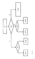
Anhand des Flussdiagramms nach
Es wird davon ausgegangen, dass das Fahrzeug in einem mit S1 bezeichneten ersten Verfahrensschritt rein elektrisch betrieben wird, wobei der E-Gang eingelegt ist. In diesem Betriebszustand sind das Gaspedal 106, welches insbesondere bei einem Elektrofahrzeug auch als Fahrpedal bezeichnet wird, sowie ein in den Figuren nicht dargestelltes Bremspedal steuerungstechnisch derart mit dem Elektromotor 11 gekoppelt, dass dieser nicht nur als Fahrantriebsmotor, sondern auch zur Rekuperation nutzbar ist. Der Sperrmechanismus SP ist hierbei aktiviert, womit insbesondere eine ungewollte Zuschaltung des verbrennungsmotorischen Antriebs unterbunden wird.It is assumed that the vehicle is operated purely electrically in a first method step designated S1, wherein the electric gear is engaged. In this operating state, the
Im Verfahrensschritt S2 wird der Schalthebel 20 manuell aus der Position E herausgenommen, soweit dies in diesem Zustand hardwaretechnisch möglich ist. Bereits in diesem Schritt S2 kann der Verbrennungsmotor 101 automatisch gestartet werden, womit ein bedeutsamer Zeitgewinn beim Umschalten zwischen elektromotorischem und verbrennungsmotorischem Antrieb erzielt wird.In step S2, the
Im Schritt S3 wird mittels der Steuereinheit 10 geprüft, ob der Sperrmechanismus SP aktiviert ist. Unter dem Begriff "Sperrmechanismus" werden hierbei sämtliche Komponenten subsummiert, die die Umschaltbarkeit zwischen den beiden Neutralstellungen N1,N2 beeinflussen, worunter auch steuerungs- und softwaretechnische Komponenten fallen. Bei aktiviertem Sperrmechanismus SP, was mit nicht getretenem Kupplungspedal 7 gleichbedeutend ist, wird im Schritt S4 der Wechsel in den verbrennungsmotorischen Betrieb blockiert.In step S3, it is checked by means of the
Ist dagegen das Kupplungspedal 7 getreten und damit der Sperrmechanismus SP deaktiviert, so kann in Schritt S5 die zweite Neutralstellung N2, das heißt die Wählgasse des Schaltgetriebes 103, angewählt werden. Sofern der Verbrennungsmotor 101 noch nicht beim Auslegen des E-Gangs gestartet wurde, wird er spätestens in der zweiten Neutralstellung N2 gestartet. Wird in dieser Neutralstellung N2 die Kupplung 102 geschlossen, ohne einen Gang einzulegen, so ist optional - ähnlich wie bei einem herkömmlichen Start-Stopp-System - ein Abschalten des Verbrennungsmotors 101 vorgesehen, welches von Parametern wie Motor- oder Außentemperatur und Batterieladezustand abhängig sein kann. Gleichzeitig wird in diesem Fall der Sperrmechanismus SP geschlossen, sodass ein erneutes Einlegen des E-Gangs nur möglich wäre, wenn das Kupplungspedal 7 wieder getreten und damit der Sperrmechanismus SP deaktiviert werden würde. Regelmäßig ist jedoch davon auszugehen, dass der Fahrer nach dem Wechsel von der ersten Neutralstellung N1 in die zweite Neutralstellung N2 einen der Gänge des Schaltgetriebes 103 einlegt und dann die Kupplung 102 schließt. Dies erfolgt im letzten Verfahrensschritt S6, womit der Wechsel in den verbrennungsmotorischen Antriebsmodus abgeschlossen ist.If, on the other hand, the
Im Diagramm nach
Befindet sich der Schalthebel 20 in der Stellung "E", so sind ferner Abhängigkeiten des Zustands des Antriebsstrangs von der Kupplungspedalstellung KS gegeben: Bei geschlossener Kupplung 102 ist der Sperrmechanismus SP verriegelt. Dieser Zustand ist mit Z11 bezeichnet. Der Verbrennungsmotor 101 ist oder wird hierbei gestoppt, sofern er nicht benötigt wird, um Energie, beispielsweise zur Erhaltung des Ladezustands oder zum Aufladen eines Generators und/oder zum Antrieb eines Kompressors einer Klimaanlage oder zur Erwärmung, zu liefern. Unabhängig vom Betriebszustand des Verbrennungsmotors 101 wird der Elektromotor 11 im Zustand Z11 bestromt, sobald das Gaspedal 106 betätigt wird.If the
Ist die Kupplung 102 dagegen geöffnet, was dem Zustand Z12 entspricht, so wird der Sperrmechanismus SP entriegelt, das heißt der Wechsel in den verbrennungsmotorischen Antriebsmodus ermöglicht. Hierbei bleibt der Verbrennungsmotor 101 in Betrieb beziehungsweise wird der Verbrennungsmotor 101 gestartet, sofern er noch nicht in Betrieb ist. Wird der Verbrennungsmotor 101 mit Leerlaufdrehzahl betrieben, so kann durch das Treten des Kupplungspedals 7, das heißt den Übergang vom Zustand Z11 in den Zustand Z12, eine automatische Erhöhung der Drehzahl des Verbrennungsmotors 101 ausgelöst werden.On the other hand, when the clutch 102 is opened, which corresponds to the state Z12, the lock mechanism SP is unlocked, that is, the changeover to the internal combustion engine drive mode is enabled. Here, the
Auch in der ersten Neutralstellung N1 des Schalthebels 20, welche aus Bedienersicht am ehesten mit der Stellung "N" des Wählhebels eines herkömmlichen Automatikfahrzeugs vergleichbar ist, sind Zustände im Antriebsstrang von der Kupplungspedalstellung KS abhängig. Solange die Kupplung 102 geschlossen ist, was dem Zustand Z 13 entspricht, bleibt der Sperrmechanismus SP verriegelt. Hat der Verbrennungsmotor 101 keine oder nur eine geringe Leistung für Nebenaggregate zu liefern, so kann der Verbrennungsmotor 101 im Zustand Z13 automatisch abgestellt werden, sofern er läuft. Mit dem Öffnen der Kupplung 102 erfolgt ein Übergang in den Zustand Z14, wobei der Sperrmechanismus SP entriegelt wird. Der Verbrennungsmotor 101 wird im Zustand Z14 gestartet, sofern er nicht bereits zu einem früheren Zeitpunkt gestartet wurde.Even in the first neutral position N1 of the
Der Zustand Z15 ist gegeben, wenn einer der Gänge G des Schaltgetriebes 103 eingelegt ist, wobei in diesem Zustand die Kupplung 102 geschlossen werden kann, um verbrennungsmotorisch anzufahren. Zusätzlich zum verbrennungsmotorischen Antrieb ist im Zustand Z15 optional eine Bestromung des Elektromotors 11 bei Betätigung des Gaspedals 106 vorgesehen.The state Z15 is given when one of the gears G of the
- 1 ... 61 ... 6
- Vorwärtsgangforward gear
- 77
- Kupplungspedalclutch pedal
- 88th
- HandschaltvorrichtungHand shifting device
- 99
- Motorsteuerungmotor control
- 1010
- Steuereinheitcontrol unit
- 1111
- Elektromotorelectric motor
- 1212
- Getriebetransmission
- 1313
- Hinterradrear wheel
- 1414
- Gehäusecasing
- 1515
- GetriebeausgangswelleTransmission output shaft
- 1616
- Hinterachserear axle
- 1717
- Kardanwellepropeller shaft
- 1818
- Getriebestufegear stage
- 1919
- Kupplungclutch
- 2020
- Schalthebel, WählelementShifter, selector
- 2121
- Gelenkjoint
- 2222
- Faltenbalgbellow
- 2323
- Mittelkonsolecenter console
- 2424
- Schaltknaufshift knob
- 2525
- Schalteinrichtungswitching device
- 2626
- Wähleinrichtungdialer
- 2727
- Sensoreinrichtungsensor device
- 2828
- Sperrelementblocking element
- 2929
- Elektromagnetelectromagnet
- 3030
- Schaltwelleshift shaft
- 3131
- Schaltfingershift finger
- 3232
- Schaltstangeshift rod
- 3333
- Rastiervorrichtunglocking device
- 3434
- Sperrbolzenlocking pin
- 101101
- Verbrennungsmotorinternal combustion engine
- 102102
- Kupplungclutch
- 103103
- Schaltgetriebemanual transmission
- 104104
- Differentialgetriebedifferential gear
- 105105
- Vorderradfront
- 106106
- Gaspedalaccelerator
- Ee
- E-GangE-course
- EGEC
- E-Gang-SignalE-speed signal
- EGmEGM
- maximales E-Gang-Signalmaximum e-gear signal
- ESIT
- Eingangssignalinput
- FF
- Betätigungskraftoperating force
- FEFE
- erhöhte Betätigungskraftincreased operating force
- GG
- Gangcorridor
- GPGP
- Gaspedalstellungaccelerator position
- ISCISC
- Inverses SchaltschemaInverse circuit diagram
- KSKS
- KupplungspedalstellungClutch pedal position
- N1N1
- Neutralstellungneutral position
- N2N2
- Neutralstellungneutral position
- nn
- Drehzahlrotation speed
- NGNG
- Drehzahl der GetriebeausgangswelleSpeed of the transmission output shaft
- NMNM
- KurbelwellendrehzahlCrankshaft speed
- NRNO
- Raddrehzahlwheel speed
- PSPS
- Pedalstellungpedal position
- RR
- Rückwärtsgangreverse gear
- S1 ... S6S1 ... S6
- Verfahrensschrittstep
- SCSC
- Schaltschemaswitching scheme
- SFSF
- Sperrkraftlocking force
- SPSP
- Sperrmechanismuslocking mechanism
- tt
- ZeitTime
- t1 t 1
- Zeitpunkttime
- VPVP
- VollgasphaseFull gas phase
- WSWS
- Wählhebelstellungselector lever position
- Z1Z1
- ZustandStatus
- Z11 ... Z15Z11 ... Z15
- ZustandStatus
Claims (10)
Applications Claiming Priority (1)
| Application Number | Priority Date | Filing Date | Title |
|---|---|---|---|
| DE102014203473 | 2014-02-26 |
Publications (2)
| Publication Number | Publication Date |
|---|---|
| EP2913563A1 true EP2913563A1 (en) | 2015-09-02 |
| EP2913563B1 EP2913563B1 (en) | 2019-07-17 |
Family
ID=52577614
Family Applications (1)
| Application Number | Title | Priority Date | Filing Date |
|---|---|---|---|
| EP15154277.6A Active EP2913563B1 (en) | 2014-02-26 | 2015-02-09 | Hybrid drive unit |
Country Status (1)
| Country | Link |
|---|---|
| EP (1) | EP2913563B1 (en) |
Cited By (11)
| Publication number | Priority date | Publication date | Assignee | Title |
|---|---|---|---|---|
| US20140208893A1 (en) * | 2011-07-13 | 2014-07-31 | Aisin Ai Co., Ltd | Manual transmission |
| WO2016151457A1 (en) * | 2015-03-20 | 2016-09-29 | Iveco S.P.A. | Selection system of a vehicular traction mode of a hybrid or multimodal vehicle |
| FR3041910A1 (en) * | 2015-10-02 | 2017-04-07 | Peugeot Citroen Automobiles Sa | DEVICE FOR SELECTING SPEEDS OF A HYBRID VEHICLE |
| DE102016207731A1 (en) | 2016-05-04 | 2017-11-09 | Schaeffler Technologies AG & Co. KG | Locking actuator for a transmission of a motor vehicle |
| FR3054189A1 (en) * | 2016-07-19 | 2018-01-26 | Peugeot Citroen Automobiles Sa | TORQUE CONTROL PROVIDED BY A MOTOR VEHICLE OF A PARALLEL HYBRID VEHICLE HAVING A MANUAL GEARBOX, ACCORDING TO THE CLUTCH |
| FR3057522A1 (en) * | 2016-10-19 | 2018-04-20 | Peugeot Citroen Automobiles Sa | METHOD FOR CONTROLLING THE REGIME OF A THERMAL MOTOR FOR A HYBRID VEHICLE COMPRISING A MANUAL TRANSMISSION |
| DE102017105101A1 (en) | 2016-12-21 | 2018-06-21 | Schaeffler Technologies AG & Co. KG | shift actuator |
| DE102016225487A1 (en) | 2016-12-19 | 2018-06-21 | Audi Ag | Clutch system for a motor vehicle, motor vehicle with a clutch system and method for operating a clutch system |
| DE102019204299A1 (en) * | 2019-03-27 | 2020-10-01 | Vitesco Technologies Germany Gmbh | Drive unit for a vehicle and method for operating a drive unit for a vehicle |
| CN113022549A (en) * | 2021-03-25 | 2021-06-25 | 潍柴动力股份有限公司 | Hybrid electric vehicle and mode switching and gear shifting coordination control method and controller thereof |
| US11167634B2 (en) | 2017-04-18 | 2021-11-09 | Magna powertrain gmbh & co kg | Drive train for a hybrid vehicle, in particular for a temporarily four wheel driven motor vehicle |
Citations (6)
| Publication number | Priority date | Publication date | Assignee | Title |
|---|---|---|---|---|
| EP1759915A2 (en) * | 1998-07-21 | 2007-03-07 | TOKYO R&D CO., LTD. | Hybrid vehicle and method of controlling its running |
| DE102008042682A1 (en) | 2007-10-09 | 2009-04-23 | Toyota Jidosha Kabushiki Kaisha, Toyota-shi | Hybrid vehicle drive system |
| DE102007052261A1 (en) | 2007-11-02 | 2009-05-07 | Bayerische Motoren Werke Aktiengesellschaft | Hybrid vehicle, has selecting element allowing driver to switch gear from gear ratio to other gear ratio, while carrying out switching procedures from former ratio to latter ratio by operation of selecting element |
| DE102010023093A1 (en) | 2010-05-31 | 2011-12-01 | Gertrag Ford Transmissions Gmbh | Drive train for motor vehicle, has drive unit which has internal combustion engine and is formed to drive axle of motor vehicle |
| DE102012203584A1 (en) * | 2012-03-07 | 2013-09-12 | Bayerische Motoren Werke Aktiengesellschaft | Method for switching a hybrid drive from one operating mode to another operating mode or hybrid vehicle |
| US20140004996A1 (en) * | 2011-04-18 | 2014-01-02 | Aisin Ai Co., Ltd. | Power transmission control apparatus for vehicle |
-
2015
- 2015-02-09 EP EP15154277.6A patent/EP2913563B1/en active Active
Patent Citations (6)
| Publication number | Priority date | Publication date | Assignee | Title |
|---|---|---|---|---|
| EP1759915A2 (en) * | 1998-07-21 | 2007-03-07 | TOKYO R&D CO., LTD. | Hybrid vehicle and method of controlling its running |
| DE102008042682A1 (en) | 2007-10-09 | 2009-04-23 | Toyota Jidosha Kabushiki Kaisha, Toyota-shi | Hybrid vehicle drive system |
| DE102007052261A1 (en) | 2007-11-02 | 2009-05-07 | Bayerische Motoren Werke Aktiengesellschaft | Hybrid vehicle, has selecting element allowing driver to switch gear from gear ratio to other gear ratio, while carrying out switching procedures from former ratio to latter ratio by operation of selecting element |
| DE102010023093A1 (en) | 2010-05-31 | 2011-12-01 | Gertrag Ford Transmissions Gmbh | Drive train for motor vehicle, has drive unit which has internal combustion engine and is formed to drive axle of motor vehicle |
| US20140004996A1 (en) * | 2011-04-18 | 2014-01-02 | Aisin Ai Co., Ltd. | Power transmission control apparatus for vehicle |
| DE102012203584A1 (en) * | 2012-03-07 | 2013-09-12 | Bayerische Motoren Werke Aktiengesellschaft | Method for switching a hybrid drive from one operating mode to another operating mode or hybrid vehicle |
Cited By (19)
| Publication number | Priority date | Publication date | Assignee | Title |
|---|---|---|---|---|
| US20140208893A1 (en) * | 2011-07-13 | 2014-07-31 | Aisin Ai Co., Ltd | Manual transmission |
| WO2016151457A1 (en) * | 2015-03-20 | 2016-09-29 | Iveco S.P.A. | Selection system of a vehicular traction mode of a hybrid or multimodal vehicle |
| FR3041910A1 (en) * | 2015-10-02 | 2017-04-07 | Peugeot Citroen Automobiles Sa | DEVICE FOR SELECTING SPEEDS OF A HYBRID VEHICLE |
| DE102016207731A1 (en) | 2016-05-04 | 2017-11-09 | Schaeffler Technologies AG & Co. KG | Locking actuator for a transmission of a motor vehicle |
| DE102016207731B4 (en) | 2016-05-04 | 2018-06-07 | Schaeffler Technologies AG & Co. KG | Locking actuator for a transmission of a motor vehicle |
| FR3054189A1 (en) * | 2016-07-19 | 2018-01-26 | Peugeot Citroen Automobiles Sa | TORQUE CONTROL PROVIDED BY A MOTOR VEHICLE OF A PARALLEL HYBRID VEHICLE HAVING A MANUAL GEARBOX, ACCORDING TO THE CLUTCH |
| FR3057522A1 (en) * | 2016-10-19 | 2018-04-20 | Peugeot Citroen Automobiles Sa | METHOD FOR CONTROLLING THE REGIME OF A THERMAL MOTOR FOR A HYBRID VEHICLE COMPRISING A MANUAL TRANSMISSION |
| EP3312036A1 (en) * | 2016-10-19 | 2018-04-25 | PSA Automobiles SA | Method for controlling the rotational speed of a combustion engine for a hybrid vehicle having a manual gearbox |
| DE102016225487B4 (en) * | 2016-12-19 | 2020-09-03 | Audi Ag | Clutch system for a motor vehicle, motor vehicle with a clutch system and method for operating a clutch system |
| DE102016225487A1 (en) | 2016-12-19 | 2018-06-21 | Audi Ag | Clutch system for a motor vehicle, motor vehicle with a clutch system and method for operating a clutch system |
| WO2018113821A1 (en) | 2016-12-21 | 2018-06-28 | Schaeffler Technologies AG & Co. KG | Shifting actuator |
| DE102017105101B4 (en) | 2016-12-21 | 2019-05-29 | Schaeffler Technologies AG & Co. KG | shift actuator |
| DE102017105101A1 (en) | 2016-12-21 | 2018-06-21 | Schaeffler Technologies AG & Co. KG | shift actuator |
| US11248700B2 (en) | 2016-12-21 | 2022-02-15 | Schaeffler Technologies AG & Co. KG | Shifting actuator |
| US11167634B2 (en) | 2017-04-18 | 2021-11-09 | Magna powertrain gmbh & co kg | Drive train for a hybrid vehicle, in particular for a temporarily four wheel driven motor vehicle |
| DE102017206516B4 (en) | 2017-04-18 | 2024-04-25 | Magna powertrain gmbh & co kg | Drivetrain for a hybrid vehicle, in particular for a temporarily four-wheel drive motor vehicle |
| DE102019204299A1 (en) * | 2019-03-27 | 2020-10-01 | Vitesco Technologies Germany Gmbh | Drive unit for a vehicle and method for operating a drive unit for a vehicle |
| CN113022549A (en) * | 2021-03-25 | 2021-06-25 | 潍柴动力股份有限公司 | Hybrid electric vehicle and mode switching and gear shifting coordination control method and controller thereof |
| CN113022549B (en) * | 2021-03-25 | 2022-06-28 | 潍柴动力股份有限公司 | Hybrid electric vehicle and mode switching and gear shifting coordination control method and controller thereof |
Also Published As
| Publication number | Publication date |
|---|---|
| EP2913563B1 (en) | 2019-07-17 |
Similar Documents
| Publication | Publication Date | Title |
|---|---|---|
| EP2913563B1 (en) | Hybrid drive unit | |
| DE10136725B4 (en) | Power transmission device for a hybrid vehicle | |
| DE10158528B4 (en) | Regeneration control device and regeneration control method for a vehicle | |
| DE112014000581B4 (en) | Hybrid vehicle | |
| EP2708400B1 (en) | Method for controlling a hybrid power train | |
| DE10241457B4 (en) | Transfer case for vehicles and method for distributing a driving force on two vehicle axles | |
| DE102012217207B4 (en) | Method and device for driving a drive train of a vehicle | |
| WO2006089669A1 (en) | Drivetrain of a motor vehicle and method for operation of the drivetrain | |
| WO2009037238A2 (en) | Method for operating a drive train | |
| DE102007052261A1 (en) | Hybrid vehicle, has selecting element allowing driver to switch gear from gear ratio to other gear ratio, while carrying out switching procedures from former ratio to latter ratio by operation of selecting element | |
| DE102010022395A1 (en) | Method for operating hybrid drive system in motor vehicle, involves guiding reduced torque of auxiliary engine in coasting mode, during exchanging of gear switching stage of main engine for duration at which friction clutch is separated | |
| DE112012005972T5 (en) | Drive unit for a hybrid vehicle | |
| DE102009023499A1 (en) | Method for operating hybrid drive system with main drive machine for motor vehicle, involves coupling input shaft with main drive machine, where another input shaft is drivingly coupled with additional drive machine | |
| DE102010043250A1 (en) | Method for rock-freeing vehicle, involves identifying operating situation of vehicle, where drive moment acts in reference travel direction, and front reversal point is achieved in reference travel direction | |
| DE102010023093B4 (en) | Drive train for a motor vehicle and method for driving a motor vehicle drive train | |
| EP3221615A1 (en) | Method and device for operating a motor vehicle | |
| DE102020105616A1 (en) | BRAKE GEAR SHIFTING SYSTEMS AND CONTROL LOGIC FOR VEHICLE POWERTRAINS | |
| DE102007011507A1 (en) | Method for operation of transmission device involves leaving negotiability of control element at value, required for representation of traction in transmission device, during presentation of specification of driving | |
| WO2016141933A1 (en) | Hybrid drive unit | |
| DE102013001059A1 (en) | Method for disconnecting and switching internal combustion engine during driving operation of motor car, involves monitoring start sensor, and restarting internal combustion engine when start sensor is actuated | |
| DE102020113089A1 (en) | Drive unit for a hybrid motor vehicle with manual transmission; and methods of switching between two gears | |
| DE102010022912A9 (en) | Method for driving a motor vehicle drive train | |
| DE102013002166A1 (en) | Drive device controlling method for motor vehicle, involves operating drive device, and selecting efficiency mode of drive device by actuation of operating device based on increase in transmission ratio | |
| DE102016217575A1 (en) | Drive arrangement for a vehicle | |
| DE102011100754A1 (en) | Power train for motor vehicle e.g. hybrid vehicle, has shaft that is coupled with electric machine, when shaft is rotated in one direction and spaced apart from electric machine when shaft is rotated in reverse direction |
Legal Events
| Date | Code | Title | Description |
|---|---|---|---|
| PUAI | Public reference made under article 153(3) epc to a published international application that has entered the european phase |
Free format text: ORIGINAL CODE: 0009012 |
|
| AK | Designated contracting states |
Kind code of ref document: A1 Designated state(s): AL AT BE BG CH CY CZ DE DK EE ES FI FR GB GR HR HU IE IS IT LI LT LU LV MC MK MT NL NO PL PT RO RS SE SI SK SM TR |
|
| AX | Request for extension of the european patent |
Extension state: BA ME |
|
| 17P | Request for examination filed |
Effective date: 20160302 |
|
| RBV | Designated contracting states (corrected) |
Designated state(s): AL AT BE BG CH CY CZ DE DK EE ES FI FR GB GR HR HU IE IS IT LI LT LU LV MC MK MT NL NO PL PT RO RS SE SI SK SM TR |
|
| REG | Reference to a national code |
Ref country code: DE Ref legal event code: R079 Ref document number: 502015009637 Country of ref document: DE Free format text: PREVIOUS MAIN CLASS: F16H0061220000 Ipc: F16H0059020000 |
|
| GRAP | Despatch of communication of intention to grant a patent |
Free format text: ORIGINAL CODE: EPIDOSNIGR1 |
|
| STAA | Information on the status of an ep patent application or granted ep patent |
Free format text: STATUS: GRANT OF PATENT IS INTENDED |
|
| RIC1 | Information provided on ipc code assigned before grant |
Ipc: B60W 20/00 20160101ALI20190221BHEP Ipc: F16H 59/02 20060101AFI20190221BHEP Ipc: F16H 61/22 20060101ALI20190221BHEP |
|
| INTG | Intention to grant announced |
Effective date: 20190325 |
|
| GRAS | Grant fee paid |
Free format text: ORIGINAL CODE: EPIDOSNIGR3 |
|
| GRAA | (expected) grant |
Free format text: ORIGINAL CODE: 0009210 |
|
| STAA | Information on the status of an ep patent application or granted ep patent |
Free format text: STATUS: THE PATENT HAS BEEN GRANTED |
|
| AK | Designated contracting states |
Kind code of ref document: B1 Designated state(s): AL AT BE BG CH CY CZ DE DK EE ES FI FR GB GR HR HU IE IS IT LI LT LU LV MC MK MT NL NO PL PT RO RS SE SI SK SM TR |
|
| REG | Reference to a national code |
Ref country code: GB Ref legal event code: FG4D Free format text: NOT ENGLISH |
|
| REG | Reference to a national code |
Ref country code: CH Ref legal event code: EP |
|
| REG | Reference to a national code |
Ref country code: DE Ref legal event code: R096 Ref document number: 502015009637 Country of ref document: DE |
|
| REG | Reference to a national code |
Ref country code: IE Ref legal event code: FG4D Free format text: LANGUAGE OF EP DOCUMENT: GERMAN |
|
| REG | Reference to a national code |
Ref country code: AT Ref legal event code: REF Ref document number: 1156150 Country of ref document: AT Kind code of ref document: T Effective date: 20190815 |
|
| REG | Reference to a national code |
Ref country code: NL Ref legal event code: MP Effective date: 20190717 |
|
| REG | Reference to a national code |
Ref country code: LT Ref legal event code: MG4D |
|
| PG25 | Lapsed in a contracting state [announced via postgrant information from national office to epo] |
Ref country code: FI Free format text: LAPSE BECAUSE OF FAILURE TO SUBMIT A TRANSLATION OF THE DESCRIPTION OR TO PAY THE FEE WITHIN THE PRESCRIBED TIME-LIMIT Effective date: 20190717 Ref country code: NO Free format text: LAPSE BECAUSE OF FAILURE TO SUBMIT A TRANSLATION OF THE DESCRIPTION OR TO PAY THE FEE WITHIN THE PRESCRIBED TIME-LIMIT Effective date: 20191017 Ref country code: PT Free format text: LAPSE BECAUSE OF FAILURE TO SUBMIT A TRANSLATION OF THE DESCRIPTION OR TO PAY THE FEE WITHIN THE PRESCRIBED TIME-LIMIT Effective date: 20191118 Ref country code: HR Free format text: LAPSE BECAUSE OF FAILURE TO SUBMIT A TRANSLATION OF THE DESCRIPTION OR TO PAY THE FEE WITHIN THE PRESCRIBED TIME-LIMIT Effective date: 20190717 Ref country code: NL Free format text: LAPSE BECAUSE OF FAILURE TO SUBMIT A TRANSLATION OF THE DESCRIPTION OR TO PAY THE FEE WITHIN THE PRESCRIBED TIME-LIMIT Effective date: 20190717 Ref country code: SE Free format text: LAPSE BECAUSE OF FAILURE TO SUBMIT A TRANSLATION OF THE DESCRIPTION OR TO PAY THE FEE WITHIN THE PRESCRIBED TIME-LIMIT Effective date: 20190717 Ref country code: BG Free format text: LAPSE BECAUSE OF FAILURE TO SUBMIT A TRANSLATION OF THE DESCRIPTION OR TO PAY THE FEE WITHIN THE PRESCRIBED TIME-LIMIT Effective date: 20191017 Ref country code: LT Free format text: LAPSE BECAUSE OF FAILURE TO SUBMIT A TRANSLATION OF THE DESCRIPTION OR TO PAY THE FEE WITHIN THE PRESCRIBED TIME-LIMIT Effective date: 20190717 |
|
| PG25 | Lapsed in a contracting state [announced via postgrant information from national office to epo] |
Ref country code: AL Free format text: LAPSE BECAUSE OF FAILURE TO SUBMIT A TRANSLATION OF THE DESCRIPTION OR TO PAY THE FEE WITHIN THE PRESCRIBED TIME-LIMIT Effective date: 20190717 Ref country code: LV Free format text: LAPSE BECAUSE OF FAILURE TO SUBMIT A TRANSLATION OF THE DESCRIPTION OR TO PAY THE FEE WITHIN THE PRESCRIBED TIME-LIMIT Effective date: 20190717 Ref country code: RS Free format text: LAPSE BECAUSE OF FAILURE TO SUBMIT A TRANSLATION OF THE DESCRIPTION OR TO PAY THE FEE WITHIN THE PRESCRIBED TIME-LIMIT Effective date: 20190717 Ref country code: IS Free format text: LAPSE BECAUSE OF FAILURE TO SUBMIT A TRANSLATION OF THE DESCRIPTION OR TO PAY THE FEE WITHIN THE PRESCRIBED TIME-LIMIT Effective date: 20191117 Ref country code: GR Free format text: LAPSE BECAUSE OF FAILURE TO SUBMIT A TRANSLATION OF THE DESCRIPTION OR TO PAY THE FEE WITHIN THE PRESCRIBED TIME-LIMIT Effective date: 20191018 Ref country code: ES Free format text: LAPSE BECAUSE OF FAILURE TO SUBMIT A TRANSLATION OF THE DESCRIPTION OR TO PAY THE FEE WITHIN THE PRESCRIBED TIME-LIMIT Effective date: 20190717 |
|
| PG25 | Lapsed in a contracting state [announced via postgrant information from national office to epo] |
Ref country code: TR Free format text: LAPSE BECAUSE OF FAILURE TO SUBMIT A TRANSLATION OF THE DESCRIPTION OR TO PAY THE FEE WITHIN THE PRESCRIBED TIME-LIMIT Effective date: 20190717 |
|
| PG25 | Lapsed in a contracting state [announced via postgrant information from national office to epo] |
Ref country code: RO Free format text: LAPSE BECAUSE OF FAILURE TO SUBMIT A TRANSLATION OF THE DESCRIPTION OR TO PAY THE FEE WITHIN THE PRESCRIBED TIME-LIMIT Effective date: 20190717 Ref country code: PL Free format text: LAPSE BECAUSE OF FAILURE TO SUBMIT A TRANSLATION OF THE DESCRIPTION OR TO PAY THE FEE WITHIN THE PRESCRIBED TIME-LIMIT Effective date: 20190717 Ref country code: DK Free format text: LAPSE BECAUSE OF FAILURE TO SUBMIT A TRANSLATION OF THE DESCRIPTION OR TO PAY THE FEE WITHIN THE PRESCRIBED TIME-LIMIT Effective date: 20190717 Ref country code: EE Free format text: LAPSE BECAUSE OF FAILURE TO SUBMIT A TRANSLATION OF THE DESCRIPTION OR TO PAY THE FEE WITHIN THE PRESCRIBED TIME-LIMIT Effective date: 20190717 |
|
| PG25 | Lapsed in a contracting state [announced via postgrant information from national office to epo] |
Ref country code: CZ Free format text: LAPSE BECAUSE OF FAILURE TO SUBMIT A TRANSLATION OF THE DESCRIPTION OR TO PAY THE FEE WITHIN THE PRESCRIBED TIME-LIMIT Effective date: 20190717 Ref country code: IS Free format text: LAPSE BECAUSE OF FAILURE TO SUBMIT A TRANSLATION OF THE DESCRIPTION OR TO PAY THE FEE WITHIN THE PRESCRIBED TIME-LIMIT Effective date: 20200224 Ref country code: SM Free format text: LAPSE BECAUSE OF FAILURE TO SUBMIT A TRANSLATION OF THE DESCRIPTION OR TO PAY THE FEE WITHIN THE PRESCRIBED TIME-LIMIT Effective date: 20190717 Ref country code: SK Free format text: LAPSE BECAUSE OF FAILURE TO SUBMIT A TRANSLATION OF THE DESCRIPTION OR TO PAY THE FEE WITHIN THE PRESCRIBED TIME-LIMIT Effective date: 20190717 |
|
| REG | Reference to a national code |
Ref country code: DE Ref legal event code: R097 Ref document number: 502015009637 Country of ref document: DE |
|
| PLBE | No opposition filed within time limit |
Free format text: ORIGINAL CODE: 0009261 |
|
| STAA | Information on the status of an ep patent application or granted ep patent |
Free format text: STATUS: NO OPPOSITION FILED WITHIN TIME LIMIT |
|
| PG2D | Information on lapse in contracting state deleted |
Ref country code: IS |
|
| 26N | No opposition filed |
Effective date: 20200603 |
|
| PG25 | Lapsed in a contracting state [announced via postgrant information from national office to epo] |
Ref country code: SI Free format text: LAPSE BECAUSE OF FAILURE TO SUBMIT A TRANSLATION OF THE DESCRIPTION OR TO PAY THE FEE WITHIN THE PRESCRIBED TIME-LIMIT Effective date: 20190717 |
|
| REG | Reference to a national code |
Ref country code: CH Ref legal event code: PL |
|
| GBPC | Gb: european patent ceased through non-payment of renewal fee |
Effective date: 20200209 |
|
| REG | Reference to a national code |
Ref country code: BE Ref legal event code: MM Effective date: 20200229 |
|
| PG25 | Lapsed in a contracting state [announced via postgrant information from national office to epo] |
Ref country code: MC Free format text: LAPSE BECAUSE OF FAILURE TO SUBMIT A TRANSLATION OF THE DESCRIPTION OR TO PAY THE FEE WITHIN THE PRESCRIBED TIME-LIMIT Effective date: 20190717 Ref country code: LU Free format text: LAPSE BECAUSE OF NON-PAYMENT OF DUE FEES Effective date: 20200209 |
|
| PG25 | Lapsed in a contracting state [announced via postgrant information from national office to epo] |
Ref country code: CH Free format text: LAPSE BECAUSE OF NON-PAYMENT OF DUE FEES Effective date: 20200229 Ref country code: LI Free format text: LAPSE BECAUSE OF NON-PAYMENT OF DUE FEES Effective date: 20200229 |
|
| PG25 | Lapsed in a contracting state [announced via postgrant information from national office to epo] |
Ref country code: GB Free format text: LAPSE BECAUSE OF NON-PAYMENT OF DUE FEES Effective date: 20200209 Ref country code: IE Free format text: LAPSE BECAUSE OF NON-PAYMENT OF DUE FEES Effective date: 20200209 |
|
| PG25 | Lapsed in a contracting state [announced via postgrant information from national office to epo] |
Ref country code: BE Free format text: LAPSE BECAUSE OF NON-PAYMENT OF DUE FEES Effective date: 20200229 |
|
| REG | Reference to a national code |
Ref country code: AT Ref legal event code: MM01 Ref document number: 1156150 Country of ref document: AT Kind code of ref document: T Effective date: 20200209 |
|
| PG25 | Lapsed in a contracting state [announced via postgrant information from national office to epo] |
Ref country code: AT Free format text: LAPSE BECAUSE OF NON-PAYMENT OF DUE FEES Effective date: 20200209 |
|
| PG25 | Lapsed in a contracting state [announced via postgrant information from national office to epo] |
Ref country code: MT Free format text: LAPSE BECAUSE OF FAILURE TO SUBMIT A TRANSLATION OF THE DESCRIPTION OR TO PAY THE FEE WITHIN THE PRESCRIBED TIME-LIMIT Effective date: 20190717 Ref country code: CY Free format text: LAPSE BECAUSE OF FAILURE TO SUBMIT A TRANSLATION OF THE DESCRIPTION OR TO PAY THE FEE WITHIN THE PRESCRIBED TIME-LIMIT Effective date: 20190717 |
|
| PG25 | Lapsed in a contracting state [announced via postgrant information from national office to epo] |
Ref country code: MK Free format text: LAPSE BECAUSE OF FAILURE TO SUBMIT A TRANSLATION OF THE DESCRIPTION OR TO PAY THE FEE WITHIN THE PRESCRIBED TIME-LIMIT Effective date: 20190717 |
|
| PGFP | Annual fee paid to national office [announced via postgrant information from national office to epo] |
Ref country code: FR Payment date: 20230221 Year of fee payment: 9 |
|
| PGFP | Annual fee paid to national office [announced via postgrant information from national office to epo] |
Ref country code: IT Payment date: 20230223 Year of fee payment: 9 |
|
| P01 | Opt-out of the competence of the unified patent court (upc) registered |
Effective date: 20230523 |
|
| PGFP | Annual fee paid to national office [announced via postgrant information from national office to epo] |
Ref country code: DE Payment date: 20230419 Year of fee payment: 9 |