EP2913530A1 - Rotary pump with plastic composite structure - Google Patents
Rotary pump with plastic composite structure Download PDFInfo
- Publication number
- EP2913530A1 EP2913530A1 EP15156205.5A EP15156205A EP2913530A1 EP 2913530 A1 EP2913530 A1 EP 2913530A1 EP 15156205 A EP15156205 A EP 15156205A EP 2913530 A1 EP2913530 A1 EP 2913530A1
- Authority
- EP
- European Patent Office
- Prior art keywords
- functional
- area
- rotary pump
- region
- rotor
- Prior art date
- Legal status (The legal status is an assumption and is not a legal conclusion. Google has not performed a legal analysis and makes no representation as to the accuracy of the status listed.)
- Withdrawn
Links
Images


Classifications
-
- F—MECHANICAL ENGINEERING; LIGHTING; HEATING; WEAPONS; BLASTING
- F04—POSITIVE - DISPLACEMENT MACHINES FOR LIQUIDS; PUMPS FOR LIQUIDS OR ELASTIC FLUIDS
- F04C—ROTARY-PISTON, OR OSCILLATING-PISTON, POSITIVE-DISPLACEMENT MACHINES FOR LIQUIDS; ROTARY-PISTON, OR OSCILLATING-PISTON, POSITIVE-DISPLACEMENT PUMPS
- F04C2/00—Rotary-piston machines or pumps
- F04C2/30—Rotary-piston machines or pumps having the characteristics covered by two or more groups F04C2/02, F04C2/08, F04C2/22, F04C2/24 or having the characteristics covered by one of these groups together with some other type of movement between co-operating members
- F04C2/34—Rotary-piston machines or pumps having the characteristics covered by two or more groups F04C2/02, F04C2/08, F04C2/22, F04C2/24 or having the characteristics covered by one of these groups together with some other type of movement between co-operating members having the movement defined in groups F04C2/08 or F04C2/22 and relative reciprocation between the co-operating members
- F04C2/344—Rotary-piston machines or pumps having the characteristics covered by two or more groups F04C2/02, F04C2/08, F04C2/22, F04C2/24 or having the characteristics covered by one of these groups together with some other type of movement between co-operating members having the movement defined in groups F04C2/08 or F04C2/22 and relative reciprocation between the co-operating members with vanes reciprocating with respect to the inner member
-
- F—MECHANICAL ENGINEERING; LIGHTING; HEATING; WEAPONS; BLASTING
- F04—POSITIVE - DISPLACEMENT MACHINES FOR LIQUIDS; PUMPS FOR LIQUIDS OR ELASTIC FLUIDS
- F04C—ROTARY-PISTON, OR OSCILLATING-PISTON, POSITIVE-DISPLACEMENT MACHINES FOR LIQUIDS; ROTARY-PISTON, OR OSCILLATING-PISTON, POSITIVE-DISPLACEMENT PUMPS
- F04C14/00—Control of, monitoring of, or safety arrangements for, machines, pumps or pumping installations
- F04C14/18—Control of, monitoring of, or safety arrangements for, machines, pumps or pumping installations characterised by varying the volume of the working chamber
- F04C14/22—Control of, monitoring of, or safety arrangements for, machines, pumps or pumping installations characterised by varying the volume of the working chamber by changing the eccentricity between cooperating members
- F04C14/223—Control of, monitoring of, or safety arrangements for, machines, pumps or pumping installations characterised by varying the volume of the working chamber by changing the eccentricity between cooperating members using a movable cam
- F04C14/226—Control of, monitoring of, or safety arrangements for, machines, pumps or pumping installations characterised by varying the volume of the working chamber by changing the eccentricity between cooperating members using a movable cam by pivoting the cam around an eccentric axis
-
- F—MECHANICAL ENGINEERING; LIGHTING; HEATING; WEAPONS; BLASTING
- F04—POSITIVE - DISPLACEMENT MACHINES FOR LIQUIDS; PUMPS FOR LIQUIDS OR ELASTIC FLUIDS
- F04C—ROTARY-PISTON, OR OSCILLATING-PISTON, POSITIVE-DISPLACEMENT MACHINES FOR LIQUIDS; ROTARY-PISTON, OR OSCILLATING-PISTON, POSITIVE-DISPLACEMENT PUMPS
- F04C15/00—Component parts, details or accessories of machines, pumps or pumping installations, not provided for in groups F04C2/00 - F04C14/00
- F04C15/06—Arrangements for admission or discharge of the working fluid, e.g. constructional features of the inlet or outlet
-
- F—MECHANICAL ENGINEERING; LIGHTING; HEATING; WEAPONS; BLASTING
- F04—POSITIVE - DISPLACEMENT MACHINES FOR LIQUIDS; PUMPS FOR LIQUIDS OR ELASTIC FLUIDS
- F04C—ROTARY-PISTON, OR OSCILLATING-PISTON, POSITIVE-DISPLACEMENT MACHINES FOR LIQUIDS; ROTARY-PISTON, OR OSCILLATING-PISTON, POSITIVE-DISPLACEMENT PUMPS
- F04C18/00—Rotary-piston pumps specially adapted for elastic fluids
- F04C18/30—Rotary-piston pumps specially adapted for elastic fluids having the characteristics covered by two or more of groups F04C18/02, F04C18/08, F04C18/22, F04C18/24, F04C18/48, or having the characteristics covered by one of these groups together with some other type of movement between co-operating members
- F04C18/34—Rotary-piston pumps specially adapted for elastic fluids having the characteristics covered by two or more of groups F04C18/02, F04C18/08, F04C18/22, F04C18/24, F04C18/48, or having the characteristics covered by one of these groups together with some other type of movement between co-operating members having the movement defined in group F04C18/08 or F04C18/22 and relative reciprocation between the co-operating members
-
- F—MECHANICAL ENGINEERING; LIGHTING; HEATING; WEAPONS; BLASTING
- F04—POSITIVE - DISPLACEMENT MACHINES FOR LIQUIDS; PUMPS FOR LIQUIDS OR ELASTIC FLUIDS
- F04C—ROTARY-PISTON, OR OSCILLATING-PISTON, POSITIVE-DISPLACEMENT MACHINES FOR LIQUIDS; ROTARY-PISTON, OR OSCILLATING-PISTON, POSITIVE-DISPLACEMENT PUMPS
- F04C28/00—Control of, monitoring of, or safety arrangements for, pumps or pumping installations specially adapted for elastic fluids
- F04C28/18—Control of, monitoring of, or safety arrangements for, pumps or pumping installations specially adapted for elastic fluids characterised by varying the volume of the working chamber
-
- F—MECHANICAL ENGINEERING; LIGHTING; HEATING; WEAPONS; BLASTING
- F04—POSITIVE - DISPLACEMENT MACHINES FOR LIQUIDS; PUMPS FOR LIQUIDS OR ELASTIC FLUIDS
- F04C—ROTARY-PISTON, OR OSCILLATING-PISTON, POSITIVE-DISPLACEMENT MACHINES FOR LIQUIDS; ROTARY-PISTON, OR OSCILLATING-PISTON, POSITIVE-DISPLACEMENT PUMPS
- F04C29/00—Component parts, details or accessories of pumps or pumping installations, not provided for in groups F04C18/00 - F04C28/00
- F04C29/12—Arrangements for admission or discharge of the working fluid, e.g. constructional features of the inlet or outlet
-
- F—MECHANICAL ENGINEERING; LIGHTING; HEATING; WEAPONS; BLASTING
- F04—POSITIVE - DISPLACEMENT MACHINES FOR LIQUIDS; PUMPS FOR LIQUIDS OR ELASTIC FLUIDS
- F04C—ROTARY-PISTON, OR OSCILLATING-PISTON, POSITIVE-DISPLACEMENT MACHINES FOR LIQUIDS; ROTARY-PISTON, OR OSCILLATING-PISTON, POSITIVE-DISPLACEMENT PUMPS
- F04C2230/00—Manufacture
- F04C2230/20—Manufacture essentially without removing material
- F04C2230/21—Manufacture essentially without removing material by casting
-
- F—MECHANICAL ENGINEERING; LIGHTING; HEATING; WEAPONS; BLASTING
- F04—POSITIVE - DISPLACEMENT MACHINES FOR LIQUIDS; PUMPS FOR LIQUIDS OR ELASTIC FLUIDS
- F04C—ROTARY-PISTON, OR OSCILLATING-PISTON, POSITIVE-DISPLACEMENT MACHINES FOR LIQUIDS; ROTARY-PISTON, OR OSCILLATING-PISTON, POSITIVE-DISPLACEMENT PUMPS
- F04C2240/00—Components
- F04C2240/10—Stators
-
- F—MECHANICAL ENGINEERING; LIGHTING; HEATING; WEAPONS; BLASTING
- F04—POSITIVE - DISPLACEMENT MACHINES FOR LIQUIDS; PUMPS FOR LIQUIDS OR ELASTIC FLUIDS
- F04C—ROTARY-PISTON, OR OSCILLATING-PISTON, POSITIVE-DISPLACEMENT MACHINES FOR LIQUIDS; ROTARY-PISTON, OR OSCILLATING-PISTON, POSITIVE-DISPLACEMENT PUMPS
- F04C2240/00—Components
- F04C2240/20—Rotors
Definitions
- the invention relates to a rotary pump with at least one pump component which consists entirely or only partially of plastic.
- the invention can be used advantageously on both a rotary pump for an incompressible fluid, i. in a positive displacement pump, as well as a rotary pump for a compressible fluid, i. in a gas pump such as in particular a vacuum pump, be realized.
- the rotary pump is in relation to its specific delivery volume, i. with respect to the delivery volume per revolution of a conveyor rotor, adjustable, preferably adjustable.
- the pump may, for example, be an internal gear pump or pendulum slide pump, but the pump is preferably a single or multi-leaf vane pump.
- the invention is based on a rotary pump, preferably a vane pump, which has a housing with an inlet and an outlet for a fluid to be conveyed and a delivery chamber connected to the inlet and the outlet, a delivery rotor which can be rotated in the delivery chamber about an axis of rotation and the delivery rotor having surrounding adjusting structure.
- the delivery chamber can already be bounded solely by the housing and the adjusting structure and thus determined. In principle, however, it is conceivable that the delivery chamber is first limited by means of one or possibly several further structures.
- the delivery rotor and the actuator structure form delivery cells in which fluid can be delivered by rotating the delivery rotor from the inlet to the outlet by moving the delivery cells such as internal gear pumps and shuttle pumps, and more particularly Wing pumps known to increase on a low pressure side of the delivery chamber and reduce again on a high pressure side of the delivery chamber.
- the adjusting structure is movable relative to the conveyor rotor back and forth, preferably transversely to the axis of rotation of the conveyor rotor.
- the adjusting structure can in particular be arranged pivotably or linearly movably in the housing in order to be able to adjust the specific delivery volume.
- the conveying rotor comprises a rotor structure.
- the rotor structure can already form the conveyor rotor, which would be integral in such embodiments.
- a one-piece design is given for example in internal gear pumps.
- a vane pump has a one-piece conveying rotor, so that the terms "conveying rotor” and "rotor structure” can refer to the same part.
- a conveying rotor formed as a one-piece impeller may, for example, have elastically yielding wings which yield materially elastic in order to be able to form the increasing and decreasing conveying cells.
- a conveying rotor formed as an impeller is more preferably in several parts and has the rotor structure central in such embodiments and projecting outwardly therefrom one or more vanes, which are or are movable relative to the rotor structure as a whole, preferably slidingly.
- Preferred examples of single and multi-blade rotary pumps can be found in US Pat DE 10 2011 086 175 B3 and the DE 10 2008 036 273 B4 ,
- the adjusting structure and / or the rotor structure is or are a composite material structure.
- the respective composite material structure has a molding area made of plastic and a functional area immovably fixed to the molding area and made of a functional material of a different chemical composition than the plastic of the molding area.
- the at least two different materials may also differ from each other in other respects, for example, in terms of their density or with respect to additives such as embedded reinforcing fibers or other reinforcing or functional body, which, if present, in the respective material in larger numbers at least substantially homogeneously distributed.
- the functional material may in particular be a metallic material, such as a light metal or a light metal alloy or preferably a steel.
- the metallic functional material may in particular be a cast body or sintered body with a cast structure or a sintered structure.
- the functional material may instead also be a plastic.
- the molding area is larger in volume and / or mass than the functional area.
- the functional area is expediently an area in which the Composite structure of a particular load, such as is subject to sliding friction or otherwise exposed to wear. Accordingly, in such a function, a sliding material is selected as the functional material. However, instead of or in combination with good sliding properties, the functional material may also be chosen with a view to increasing the rigidity or improving another property of the composite material structure.
- the composite material structure may consist of a single contiguous molding region and a single contiguous functional region. But it can also have multiple functional areas of either the same functional material or different functional materials. It may also have two or more mold portions made of the same plastic, wherein the plurality of mold portions are not contiguous, but are separated from each other by the one or more functional portions.
- the molding area and the functional area can be made in a common molding process, such as injection molding, for example by co-injection if the functional material is also a plastic.
- the composite material structure comprises one molding area and a plurality of functional areas or has a plurality of mutually separate molding areas, for which in such variants more than two structural areas.
- the functional region or the optionally a plurality of functional regions is produced separately from the molding region or optionally a plurality of molding regions and is durably firmly bonded to the mold region (s) during molding of the molding region or optionally a plurality of molding regions, preferably with a positive fit.
- a functional area can be completely or at least partially encapsulated, in particular during the production of the molding area with the plastic of the molding area.
- the molding region and the functional region can be connected to one another by frictional engagement and / or material bonding and / or positive engagement.
- the connection is based in preferred embodiments, at least on positive engagement.
- the different areas can basically be made separately from each other and connected by means of joint connection.
- a solid compound is more preferably produced in a method of forming the molding area by inserting the prefabricated functional area into a mold, such as a plastic injection mold and completely or at least partially reshaping it with the plastic of the mold area.
- a plastic is preferably used as the plastic of the molding area, which is cheaper per mass and / or volume unit than the functional material.
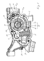
- FIG. 1 shows a rotary pump, for example in vane-type.
- the rotary pump is shown in a side view of a housing 1 of the pump. A cover of the housing 1 is removed, so that the functional components of the rotary pump can be seen.
- the housing 1 forms side walls of a delivery chamber 2, in which a delivery rotor 10 about an axis of rotation R 10 rotatable is arranged.
- the housing 1 has an inlet 3 and an outlet 4 for a fluid to be conveyed, for example engine lubricating oil.
- the delivery chamber 2 includes a low pressure side and a high pressure side. In a rotary drive of the conveyor rotor 10 in the drawn direction of rotation, clockwise, fluid flows through the inlet 3 on the low pressure side in the delivery chamber 2 and is ejected by increasing the pressure on the high pressure side and discharged via the outlet 4.
- the conveyor rotor 10 is an impeller with a central rotor structure 11 with respect to the axis of rotation R 10 and vanes 12 distributed over the circumference of the rotor structure 11.
- the vanes 12 are in slots 13 of the rotor structure 11 which are open to the outer periphery of the rotor structure 11 in the radial or at least in the Slidably guided substantially radial direction slidably.
- the rotor structure 11 is rotatably connected to a rotatable shaft about the axis of rotation R 10 in a form-fitting based joining engagement.
- a joining surface which may be shaped in particular in the manner of a toothing.
- the joining surface is preferably shaped so that the rotor structure 11 can be pushed with its joining surface axially on the shaft.
- the conveyor rotor 10 is surrounded at its outer periphery by a setting structure 20, which is exemplified as an adjusting ring.
- a setting structure 20 which is exemplified as an adjusting ring.
- the axis of rotation R 10 of the conveyor rotor 10 is arranged eccentrically to a parallel central axis of the actuator structure 20, so that the delivery rotor 10 and the adjusting ring 20 formed conveying cells upon rotation of the delivery rotor 10 on the low-pressure side of the delivery chamber 2 in the direction of rotation increase and reduce again on the high-pressure side. Because of this with the speed of the conveyor rotor 10 periodic increase and decrease in the delivery cells, the fluid from the low pressure side to the high pressure side and there promoted with increased pressure through the outlet 4.
- the so-called specific delivery volume can be adjusted. If the fluid is a liquid and thus incompressible to a good approximation, the absolute delivery volume is directly proportional to the speed of the delivery rotor 10. For compressible fluids, such as air, the relationship between flow rate and speed is not linear, but the absolute flow rate or mass also increases with the speed.
- the specific delivery volume depends on the eccentricity, ie the distance between the central axis of the adjusting structure 20 and the axis of rotation R 10 of the conveyor rotor 10.
- the adjusting structure 20 is movably arranged in the housing 1, for example pivotable about a pivot axis R 20 .
- a modified actuator structure in the housing 1 can also be arranged linearly movable.
- a mobility transverse to the axis of rotation R 10 of the conveyor rotor 10 is preferred.
- an axial adjustability would also be conceivable by which an axial width of the delivery cells can be adjusted.
- a pivot bearing region of the actuating structure 20 is designated by 21.
- the pivot bearing is designed as a sliding bearing by the adjusting structure 20 is in its pivot bearing portion 21 with a mating surface of the housing 1 directly in sliding contact.
- the adjusting structure 20 is acted upon by a control fluid pressure acting in the direction of adjustment S.
- This control pressure counteracts a restoring force in the opposite direction.
- the restoring force is generated by a spring device with one or more mechanical spring members, in the embodiment a single spring member 5.
- the spring member 5 is designed and arranged as a helical compression spring.
- a control pressure chamber 6 is formed in the housing 1, into which the control fluid can be introduced to exert on the actuator structure action region 23 and via this on the actuator structure 20 a force acting in the direction of adjustment S force.
- the restoring force likewise acts directly on the adjusting structure-influencing region 23.
- the control pressure chamber 6 is supplied with the pressure fluid delivered by the rotary pump to pressurize the actuator structure 20 in the direction of adjustment S with the control fluid pressure.
- the adjustment direction S is selected such that the eccentricity between the conveying rotor 10 and the adjusting structure 20 and thereby the specific delivery volume decreases when the adjusting structure 20 moves in the direction of adjustment S.
- the adjusting structure 20 forms with the housing 1 a sealing gap which separates the control pressure chamber 6 in the direction of adjustment S from the low-pressure region.
- a sealing element for better sealing of the sealing gap arranged.
- the sealing element is arranged in a receptacle 24 of the adjusting structure 20.
- the adjusting structure 20 and / or the rotor structure 11 are or are in each case composite material structures which consist entirely or at least partially of plastic. However, they are made of at least two materials that differ in terms of their chemical composition, optionally also in terms of aggregates.
- the adjusting structure 20 has a molding area 25 made of plastic and a functional area 26 made of a functional material whose chemical composition differs from the plastic of the molding area 25.
- the functional material may be another plastic or in particular a metal or a metal alloy. It is preferably steel.
- the functional area 26 can advantageously be a cast or sintered body.
- the functional area 26 is ring, sleeve or tubular. It may have an at least substantially smooth surface, in particular a smooth inner circumferential surface.
- the functional area 26 is embedded in the molding area 25.
- the molding area 25 further surrounds the functional area 26 over its entire outer circumference.
- the molding area 25 surrounds the functional area 26 at both axial ends.
- the functional region 26 is embedded in a groove-shaped or trough-shaped depression 28, which circulates on the inner circumference of the molding region 25.
- the molding region 25 encloses the functional region 26 over its outer circumference and axially correspondingly on both sides, so that the molding region 25 and the functional region 26 are connected in a form-fitting, fixed manner relative to one another in an axially immovable manner. A relative movement in the circumferential direction is prevented by a correspondingly firm grip of the functional area 26.
- Forming area 25 and functional area 26 together form the smooth inner peripheral surface 27 of the adjusting structure 20 as a sliding surface.
- the molding area 25 and the functional area 26 advantageously already form the complete actuator structure 20 alone.
- the functional area 26 forms an insert or insert.
- the functional area 26 can, as already mentioned, be a steel insert or another metallic insert or else a plastic insert.
- the functional area 26 is sufficiently rigid that it serves as supporting and / or stiffening body for the forming area 25 within the adjusting structure 20, ie the forming area 25 can be supported on the functional area 26 and / or the shape retention of the adjusting structure 20 can be improved during pump operation ,
- the functional region 26 may be made of a sliding material or coated with a sliding material instead or in combination with a support or stiffening function, wherein the sliding material has the same or preferably a lower coefficient of friction with respect to the sliding friction and preferably also with respect to the static friction the plastic of the molding area 25 may have.
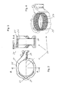
- FIGS. 5 and 6 show a composite material structure of a second embodiment.
- the adjusting structure 20 also differs from the first exemplary embodiment only in that the functional area 26 extends over the entire axial width of the adjusting structure 20 and thus alone forms the inner peripheral surface 27, via which the wings 12 of the conveyor rotor 10 with rotary drive of the conveyor rotor 10.
- the functional area 26 is annular, sleeve or tubular with a small wall thickness compared to the inner diameter.
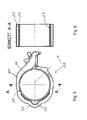
- a third embodiment of a composite material structure 20, again the adjusting structure 20, is in the FIGS. 7 and 8 shown.
- the functional region 26 also extends over the entire axial width of the actuating structure 20 in the third exemplary embodiment.
- the functional region 26 differs from that of the second exemplary embodiment by a radial projection 29 provided on the outer circumference and into a groove-shaped depression 28 of the molding region 25 engages and thereby secures the functional area 26 on the molding area 25 axially in addition to the solid wrap around the mold area 25.
- the functional area 26 in the third embodiment corresponds to the functional area 26 of the second embodiment.
- Recess 28 and Abragung 29 may be completely or only partially formed circumferentially and interlock.
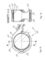
- the functional region 26 encloses the forming region 25 axially on both sides, in that the functional region 26, which essentially forms a thin-walled tube, has a flange 29 protruding outwards at its two axial ends advantageously completely circulate. Axially between the two flanges 29 The functional region 26 accordingly forms a depression 28 into which the molding region 25 engages and which preferably fills the molding region 25. The two flanges 29 secure the functional area 26 axially.
- the molding area 25 surrounds the axial section of the functional area 26, which extends between the flanges 29, in a force-locking manner.
- a frictional connection can, as in the other exemplary embodiments, also occur when the functional insert 26 is reshaped with the molding area plastic due to the solidification of the plastic of the molding area 25.
- the functional area 26 can, as in the previous exemplary embodiments, serve as a support and / or stiffening structure for the molding area 25.
- the functional region 26 forms the inner peripheral surface 27 and is therefore preferably made of a sliding material having the good sliding properties and wear resistance required for pump operation.
- the comments on the other exemplary embodiments apply equally to the fourth exemplary embodiment.
- the functional area 26 can be provided in particular as an insert or insert body and formed with the plastic of the molding area, preferably encapsulated.
- FIG. 11 is the functional area 26 removed from the composite material structure 20 shown alone.
- the functional region 26, as in the exemplary embodiments explained above, can in particular form a metal or plastic insert, preferably a steel insert, within the composite material structure 20.
- FIGS. 12 and 13 a fifth exemplary embodiment of a setting structure 20 formed as a composite material structure is illustrated.
- the actuator structure 20 of the fifth embodiment is composed of only two areas, the molding area 25 made of plastic and the functional area 26 of functional material.
- the functional region 26, as in the embodiments described above, is annular, sleeve-shaped or tubular with a smaller wall thickness compared to the inner diameter. It has a plurality of passages 30 distributed over its circumference.
- the functional area 26 can also be referred to as a perforated hollow structure.
- the passages 30 are penetrated by the plastic of the molding area 25, so that the molding area 25 and the functional area 26 are anchored to one another and a particularly intimate positive connection is obtained.
- the sleeve, ring or tubular insert 26, which forms the functional region 26 in the composite material structure 20, is in FIG. 14 detached from the composite material structure shown alone.
- the functional area 26, or the structural part or insert forming it can be inserted into a mold and can be inserted with the plastic of the mold area 25 deformed, preferably overmoulded.
- the plastic of the molding area 25 preferably penetrates into the passages 30 and thereby anchors the functional area 26 on the molding area 25.
- the functional area 26 may support and / or stiffen the molding area 25.
- the functional areas 26 of the first to fifth embodiments can be surrounded on the outside and inside by the plastic of the molding area 25 or can also be completely embedded in the plastic of the molding area 25, so that they do not have a sliding function in the modifications, but merely support and / or stiffening function have the composite material structure 20.
- the inner circumferential surface 27 serving as a sliding surface is formed by the plastic of the molding area 25 in the modifications.
- the functional regions 26 of the first to fourth exemplary embodiments may additionally have passages, such as the passages 30, in order to additionally obtain an anchoring of the regions 25 and 26 to one another in addition to the positive connection existing in the respective exemplary embodiment.
- the functional area 26 in all examples may have an outwardly projecting rib or at one or both axial ends a protruding flange and / or not extend over the entire axial length of the actuator structure 20, but approximately as in the first embodiment, the local functional area 26th be embedded axially.
- FIGS. 15 and 16 show a sixth embodiment of a formed as a composite material structure actuator structure 20.
- This actuator structure 20 includes a mold portion 25, which forms the bearing portion 21 with the sliding bearing surface 22 and on the opposite side of the Einwirk Scheme 23 in one piece as in the embodiments described above.
- the adjusting structure 20 furthermore has a first functional region 26 made of a first functional material and a further, second functional region 31 made of a second functional material.
- the first and also the second functional material differ from the plastic of the molding area 25 at least with regard to their chemical composition. They also differ in preferred embodiments with each other in the chemical composition.
- the functional materials are plastics, they can differ from each other, at least in terms of aggregates.
- one functional material may be a fiber-reinforced plastic and the other may be a plastic without fiber reinforcement or a plastic with fibers of another type.
- both functional materials are formed as plastics, then, for example, the plastic forming the functional region 26 may contain carbon fibers in order to obtain good sliding properties for the inner circumferential surface 27, which it alone forms or at least forms as a sliding surface.
- the functional material of the functional region 31 can be, for example, glass-fiber reinforced or consist of a plastic which is more dimensionally stable than the functional material of the functional region 26.
- the functional region 26 is plastic or metal with good sliding properties and sufficiently high wear resistance
- the second functional region 31 is made of metal, preferably steel.
- the first functional region 26 and / or the second functional region 31 is or are each preferably provided as a prefabricated insert, advantageously made of a metallic material or plastic.
- the second functional region 31 is used in preferred embodiments as a support and / or stiffening structure and may in particular in such embodiments of metallic material, preferably steel exist. It can be provided for example as a prefabricated sintered body or cast body.
- the first functional region 26 and / or in particular the second functional region 31 may or may each have passages, such as passages such as the passages 30 of the previous embodiment, and correspondingly be penetrated by the plastic material in the primary molding of the mold region 25 in order to obtain a more intimate positive connection.
- the two functional regions 26 and 31 can be provided in particular as inserts, inserted into a mold, for example a plastic injection mold, and shaped, preferably encapsulated, with the plastic of the mold region 25.
- the functional area 26 and also the further functional area 31 are each formed at least essentially as a hollow profile structure and surround or surround the remaining free internal cross section of the actuating structure 20 in which the conveyor rotor 10 is arranged.
- a functional area made of a material that, as described, differs from the plastic of the molding area 25 can instead also form another area of the positioning structure 20.
- the sliding surface 22 of the bearing area 21 or the entire bearing area 21 can be formed as such a functional area from a functional material.
- the functional material of such a functional area is preferably a sliding material with good sliding properties and sufficient wear resistance for the sliding friction loads occurring in the pivot bearing of the adjusting structure 20.
- Such a functional area may additionally or in principle also be provided instead of the functional areas 26 and 31 explained.
- FIGS. 17 and 18 is a composite material structure of a seventh embodiment shown, which can form the rotor structure 11 in the rotary pump and is accordingly provided with the reference numeral "11".
- the rotor structure 11 has a passage in the central area, which is enclosed by an inner peripheral surface.
- the inner peripheral surface is formed as a joining surface 19 for producing a rosununbeweglichen connection with a drive shaft of the rotary pump.
- the peripheral surface or joining surface 19 is therefore not circular. In the exemplary embodiment, it is shaped in the manner of an internal toothing.
- the outer shape of the rotor structure 11 may be formed as conventional rotor structures of vane pumps.
- the rotor structure 11 is designed as a composite material structure and accordingly comprises a molding area 15 made of a plastic and a functional area 16 made of a functional material of a different chemical composition than the plastic of the molding area 15.
- the functional material may in particular be a plastic or a metallic material, preferably a steel.
- the functional area 16 advantageously as a prefabricated insert or as a prefabricated EinlegeMech provided and formed with the plastic of the molding area 15, preferably encapsulated and in particular encapsulated.
- the functional region 16 forms the joining surface 19, thus serving as joining region, and supports and stiffens the molding region 15.
- the functional region 16 has indentations 18 distributed over its circumference, into which plastic has penetrated in the original molding of the molding region 15.
- the recesses 18 are preferably pocket-shaped widened radially inwardly, so that the plastic of the molding area 15 surrounds the functional area 16 not only on the circumference outside, but also engages behind the openings of the pockets or recesses 18 from the outer periphery, whereby a Anchoring effect is achieved.
- the wings 12 ( FIG. 1 ) slide in the slots 13 during retraction and extension of the lateral slot walls, which form corresponding sliding surfaces 14 for the wings 12.
- the slots 13 are formed in the molding area 15 so that the plastic of the molding area 15 forms the sliding surfaces 14.
- the functional area 16 has a central hollow profile, the inner peripheral surface of which is the joining surface 19.
- the functional area 16 also has projections which protrude radially outward from the hollow profile and surround the slots 13 in the area of the respective slot base. Each adjacent Abragept form the depressions 18 between them.
- FIGS. 19 and 20 show an eighth embodiment of a composite material structure again using the example of the rotor structure 11.
- the outer shape of the rotor structure 11 of the eighth embodiment corresponds to that of the seventh embodiment.
- the rotor structure 11 forms, as in the seventh embodiment, the joining surface 19 for the positive-fit joint with the drive shaft and supports and stiffens the molding area 15.
- the functional area 16 also forms the circumferentially leading and trailing sidewalls of the slots 13 for the wings 12 in the form of the sliding surfaces 17.
- the functional material forming the functional region 16 is therefore expediently a sliding material with good sliding properties and sufficiently high wear resistance.
- the functional area 16 has short projections extending in the circumferential direction, so that the plastic of the molding area 15, which has penetrated into the depressions of the functional area 16 remaining between the slots 13, engages behind the projections of the functional area 16 and the anchoring thereby improved.
- the functional area 16 extends to the outer circumference of the rotor structure 11.
- the mold portion 15 projects beyond the functional region 16 in the axial direction, so that the molding region 15 as in the seventh embodiment and the rest
- the molding area 25 of the actuator structures 20 is formed as a single contiguous area.
- FIGS. 21 and 22 show a ninth embodiment of a composite material structure using the example of the rotor structure 11.
- the outer shape of the rotor structure 11 of the ninth embodiment corresponds to those of the seventh and eighth embodiments.
- the rotor structure 11 forms the joining surface 19 for the positive-fit connection with the drive shaft and supports and stiffens the forming region 15.
- the forming region 15 forms the circumferentially leading and trailing side walls of the slots 13 for the wings
- the functional region 16 comprises a hollow profile with a joining surface 19 formed as an inner circumferential surface.
- protrusions protrude outward from the hollow profile and into the plastic of the molding region 15, resulting in large , in the radial direction extending pressure surfaces for transmitting the torque can be obtained.
- the functional material does not clothe the slots 13, not even in the slot bottom, as in the seventh embodiment.
- the Abragonne are offset from the slots 13 in the circumferential direction. They each protrude between adjacent slots 13 into the molding area 15, which surrounds the functional area 16.
- the projections broaden radially outwardly mushroom-shaped, so that the molding area 15 and the functional area 16, as viewed from the outer circumference and from the joining surface 19, engage behind one another.
- the plastic of the molding area 15 surrounds the Abragept on the outer circumference and also on the forward and trailing sides during rotational movement. The projections stabilize the molding area and subdivide it into smaller subregions, which improves the dimensional stability of the rotor structure 11 over the operating temperature range.
- the functional region 16 advantageously as a prefabricated insert, preferably made of metal or plastic and particularly preferably made of steel, and formed with the plastic of the molding area 15, advantageously encapsulated and in particular encapsulated.
Landscapes
- Engineering & Computer Science (AREA)
- Mechanical Engineering (AREA)
- General Engineering & Computer Science (AREA)
- Details And Applications Of Rotary Liquid Pumps (AREA)
- Structures Of Non-Positive Displacement Pumps (AREA)
- Rotary Pumps (AREA)
- Applications Or Details Of Rotary Compressors (AREA)
Abstract
Rotationspumpe, vorzugsweise Flügelpumpe, umfassend: (a) ein Gehäuse (1) mit einem Einlass (3) und einem Auslass (4) für ein Fluid und einer mit dem Einlass und dem Auslass verbundenen Förderkammer (2), (b) einen in der Förderkammer (2) um eine Drehachse (R 10 ) drehbaren Förderrotor (10) mit einer in Bezug auf die Drehachse (R 10 ) zentralen Rotorstruktur (11), (c) und eine den Förderrotor (10) umgebende Stellstruktur (20), die mit dem Förderrotor (10) Förderzellen (9) bildet, um das Fluid vom Einlass (3) zum Auslass (4) zu fördern, und relativ zum Förderrotor (10) vorzugsweise quer zur Drehachse (R 10 ) hin und her beweglich ist, um ein spezifisches Fördervolumen der Rotationspumpe verstellen zu können, (d) wobei wenigstens eine der Strukturen (11, 20), nämlich die Stellstruktur (20) und/oder die Rotorstruktur (11), eine Werkstoffverbundstruktur ist und einen Formbereich (15; 25) aus Kunststoff und einen mit dem Formbereich (15; 25) fest verbundenen Funktionsbereich (16; 26) aus einem Funktionswerkstoff einer anderen chemischen Zusammensetzung als der Kunststoff des Formbereichs (15; 25) aufweist.Rotary pump, preferably vane pump, comprising: (a) a housing (1) having an inlet (3) and an outlet (4) for a fluid and a delivery chamber (2) connected to the inlet and the outlet, (b) a conveying rotor (10) rotatable in the conveying chamber (2) about an axis of rotation (R 10) with a central rotor structure (11) with respect to the axis of rotation (R 10), (c) and an actuating structure (20) surrounding the conveyor rotor (10) which forms conveyor cells (9) with the conveyor rotor (10) in order to convey the fluid from the inlet (3) to the outlet (4) and relative to the conveyor rotor (10). 10) is preferably movable transversely to the axis of rotation (R 10) back and forth in order to adjust a specific delivery volume of the rotary pump, (d) wherein at least one of the structures (11, 20), namely the adjusting structure (20) and / or the rotor structure (11), a composite material structure and a molding area (15; 25) made of plastic and with the molding area (15; 25) of a functional material of a different chemical composition than the plastic of the molding area (15, 25).
Description
Die Erfindung betrifft eine Rotationspumpe mit wenigstens einer Pumpenkomponente, die gänzlich oder nur bereichsweise aus Kunststoff besteht. Die Erfindung kann mit Vorteil sowohl bei einer Rotationspumpe für ein inkompressibles Fluid, d.h. bei einer Verdrängerpumpe, als auch bei einer Rotationspumpe für ein kompressibles Fluid, d.h. bei einer Gaspumpe wie insbesondere einer Vakuumpumpe, verwirklicht sein. Die Rotationspumpe ist in Bezug auf ihr spezifisches Fördervolumen, d.h. in Bezug auf das Fördervolumen pro Umdrehung eines Förderrotors, verstellbar, vorzugsweise regelbar. Bei der Pumpe kann es sich um beispielsweise eine Innenzahnringpumpe oder Pendelschieberpumpe handeln, bevorzugt ist die Pumpe jedoch eine ein- oder mehrflügelige Flügelpumpe.The invention relates to a rotary pump with at least one pump component which consists entirely or only partially of plastic. The invention can be used advantageously on both a rotary pump for an incompressible fluid, i. in a positive displacement pump, as well as a rotary pump for a compressible fluid, i. in a gas pump such as in particular a vacuum pump, be realized. The rotary pump is in relation to its specific delivery volume, i. with respect to the delivery volume per revolution of a conveyor rotor, adjustable, preferably adjustable. The pump may, for example, be an internal gear pump or pendulum slide pump, but the pump is preferably a single or multi-leaf vane pump.
Im Fahrzeugbau, insbesondere Automobilbau, einem bevorzugten Anwendungsgebiet der Erfindung, ist man ständig bestrebt, das Gewicht und insbesondere auch die Kosten der Fahrzeugkomponenten zu senken. Gleichwohl müssen die hohen Anforderungen an beispielsweise die mechanische Festigkeit, Verschleißfestigkeit und Dauerstandfestigkeit erfüllt werden. Aufgrund der im Serienbau hohen Stückzahlen und der damit verbundenen Skaleneffekte werden auch bei kleinsten Reduzierungen der Stückkosten über die Serie betrachtet bedeutende Kosteneinsparungen erzielt.In vehicle construction, in particular automobile construction, a preferred field of application of the invention, efforts are constantly being made to reduce the weight and, in particular, the costs of the vehicle components. Nevertheless, the high demands on, for example, the mechanical strength, wear resistance and fatigue resistance must be met. Due to the large quantities produced in series production and the associated economies of scale, significant cost savings are achieved even with the smallest reductions in unit costs over the series.
Es ist eine Aufgabe der Erfindung, die Herstellkosten einer Rotationspumpe zu verringern, die an die Rotationspumpe gestellten technischen Anforderungen aber dennoch zu erfüllen.It is an object of the invention to reduce the manufacturing costs of a rotary pump, but nevertheless to meet the technical requirements imposed on the rotary pump.
Die Erfindung geht von einer Rotationspumpe, vorzugsweise eine Flügelpumpe aus, die ein Gehäuse mit einem Einlass und einem Auslass für ein zu förderndes Fluid und einer mit dem Einlass und dem Auslass verbundenen Förderkammer, einen in der Förderkammer um eine Drehachse drehbaren Förderrotor und eine den Förderrotor umgebende Stellstruktur aufweist. Die Förderkammer kann bereits allein vom Gehäuse und der Stellstruktur umgrenzt und somit bestimmt werden. Grundsätzlich ist jedoch denkbar, dass die Förderkammer erst mittels einer oder gegebenenfalls auch mehreren weiteren Strukturen begrenzt wird. Der Förderrotor und die Stellstruktur bilden Förderzellen, in denen das Fluid durch Drehen des Förderrotors vom Einlass zum Auslass gefördert werden kann, indem sich die Förderzellen wie von Innenzahnringpumpen und Pendelschieberpumpen und insbesondere Flügelpumpen bekannt, auf einer Niederdruckseite der Förderkammer vergrößern und auf einer Hochdruckseite der Förderkammer wieder verkleinern. Um das spezifische Fördervolumen verstellen zu können, ist die Stellstruktur relativ zum Förderrotor hin und her beweglich, vorzugsweise quer zur Drehachse des Förderrotors. Die Stellstruktur kann im Gehäuse insbesondere schwenkbeweglich oder linearbeweglich angeordnet sein, um das spezifische Fördervolumen verstellen zu können.The invention is based on a rotary pump, preferably a vane pump, which has a housing with an inlet and an outlet for a fluid to be conveyed and a delivery chamber connected to the inlet and the outlet, a delivery rotor which can be rotated in the delivery chamber about an axis of rotation and the delivery rotor having surrounding adjusting structure. The delivery chamber can already be bounded solely by the housing and the adjusting structure and thus determined. In principle, however, it is conceivable that the delivery chamber is first limited by means of one or possibly several further structures. The delivery rotor and the actuator structure form delivery cells in which fluid can be delivered by rotating the delivery rotor from the inlet to the outlet by moving the delivery cells such as internal gear pumps and shuttle pumps, and more particularly Wing pumps known to increase on a low pressure side of the delivery chamber and reduce again on a high pressure side of the delivery chamber. In order to adjust the specific delivery volume, the adjusting structure is movable relative to the conveyor rotor back and forth, preferably transversely to the axis of rotation of the conveyor rotor. The adjusting structure can in particular be arranged pivotably or linearly movably in the housing in order to be able to adjust the specific delivery volume.
Der Förderrotor umfasst eine Rotorstruktur. Die Rotorstruktur kann bereits den Förderrotor bilden, der in derartigen Ausführungen einteilig wäre. Eine einteilige Ausbildung ist beispielsweise bei Innenzahnringpumpen gegeben. Grundsätzlich ist auch denkbar, dass eine Flügelpumpe einen einteiligen Förderrotor aufweist, so dass die Begriffe "Förderrotor" und "Rotorstruktur" das gleiche Teil bezeichnen können. Ein als einteiliges Flügelrad gebildeter Förderrotor kann beispielsweise elastisch nachgiebige Flügel aufweisen, die materialelastisch nachgeben, um die sich vergrößernden und wieder verkleinernden Förderzellen bilden zu können. Bevorzugter ist ein als Flügelrad gebildeter Förderrotor jedoch mehrteilig und weist die in derartigen Ausführungen zentrale Rotorstruktur und von dieser nach außen abragend einen oder mehrere Flügel auf, der oder die jeweils im Ganzen relativ zur Rotorstruktur beweglich, vorzugsweise gleitbeweglich ist oder sind. Bevorzugte Beispiele für einund mehrflügelige Rotationspumpen finden sich in der
Nach der Erfindung ist oder sind die Stellstruktur und/oder die Rotorstruktur eine Werkstoffverbundstruktur. Die jeweilige Werkstoffverbundstruktur weist einen Formbereich aus Kunststoff und einen mit dem Formbereich unbeweglich, fest verbundenen Funktionsbereich aus einem Funktionswerkstoff einer anderen chemischen Zusammensetzung als der Kunststoff des Formbereichs auf. Die wenigstens zwei unterschiedlichen Werkstoffe können sich ferner auch noch in anderer Hinsicht voneinander unterscheiden, beispielsweise in Bezug auf ihre Dichte oder in Bezug auf Zusatzstoffe, wie etwa eingelagerte Verstärkungsfasern oder andere Verstärkungs- oder Funktionskörper, die, falls vorhanden, im jeweiligen Werkstoff in größerer Zahl zumindest im Wesentlichen homogen verteilt sind. Der Funktionswerkstoff kann insbesondere ein metallischer Werkstoff sein, wie etwa ein Leichtmetall oder eine Leichtmetalllegierung oder vorzugsweise ein Stahl. Der metallische Funktionswerkstoff kann insbesondere ein Gusskörper oder Sinterkörper mit entsprechend einem Gussgefüge oder einem Sintergefüge sein. Der Funktionswerkstoff kann stattdessen aber auch ebenfalls ein Kunststoff sein.According to the invention, the adjusting structure and / or the rotor structure is or are a composite material structure. The respective composite material structure has a molding area made of plastic and a functional area immovably fixed to the molding area and made of a functional material of a different chemical composition than the plastic of the molding area. The at least two different materials may also differ from each other in other respects, for example, in terms of their density or with respect to additives such as embedded reinforcing fibers or other reinforcing or functional body, which, if present, in the respective material in larger numbers at least substantially homogeneously distributed. The functional material may in particular be a metallic material, such as a light metal or a light metal alloy or preferably a steel. The metallic functional material may in particular be a cast body or sintered body with a cast structure or a sintered structure. The functional material may instead also be a plastic.
In bevorzugten Ausführungen ist der Formbereich nach Volumen und/oder Masse größer als der Funktionsbereich. Der Funktionsbereich ist zweckmäßigerweise ein Bereich, in dem die Werkstoffverbundstruktur einer besonderen Belastung, wie etwa einer Gleitreibung unterliegt oder auf andere Weise einem Verschleiß ausgesetzt ist. Entsprechend wird bei einer derartigen Funktion ein Gleitwerkstoff als Funktionswerkstoff gewählt. Stattdessen oder in Kombination mit guten Gleiteigenschaften kann der Funktionswerkstoff jedoch auch im Hinblick auf eine Erhöhung der Steifigkeit oder Verbesserung einer anderen Eigenschaft der Werkstoffverbundstruktur gewählt sein.In preferred embodiments, the molding area is larger in volume and / or mass than the functional area. The functional area is expediently an area in which the Composite structure of a particular load, such as is subject to sliding friction or otherwise exposed to wear. Accordingly, in such a function, a sliding material is selected as the functional material. However, instead of or in combination with good sliding properties, the functional material may also be chosen with a view to increasing the rigidity or improving another property of the composite material structure.
Die Werkstoffverbundstruktur kann insbesondere aus einem einzigen zusammenhängenden Formbereich und einem einzigen zusammenhängenden Funktionsbereich bestehen. Sie kann aber auch mehrere Funktionsbereiche aus entweder jeweils dem gleichen Funktionswerkstoff oder unterschiedlichen Funktionswerkstoffen aufweisen. Sie kann auch zwei oder mehr Formbereiche aus dem gleichen Kunststoff aufweisen, wobei die mehreren Formbereiche nicht zusammenhängen, sondern insbesondere durch den oder einen von mehreren Funktionsbereichen voneinander getrennt sind.In particular, the composite material structure may consist of a single contiguous molding region and a single contiguous functional region. But it can also have multiple functional areas of either the same functional material or different functional materials. It may also have two or more mold portions made of the same plastic, wherein the plurality of mold portions are not contiguous, but are separated from each other by the one or more functional portions.
Der Formbereich und der Funktionsbereich können in einem gemeinsamen Verfahren der Urformung, wie etwa Spritzgießen, hergestellt werden, beispielsweise durch Co-Injection, falls der Funktionswerkstoff ebenfalls ein Kunststoff ist. Das Gleiche gilt, wenn sich die Werkstoffverbundstruktur aus einem Formbereich und mehreren Funktionsbereichen zusammensetzt oder mehrere voneinander getrennte Formbereiche aufweist, für die in derartigen Varianten mehr als zwei Strukturbereiche.The molding area and the functional area can be made in a common molding process, such as injection molding, for example by co-injection if the functional material is also a plastic. The same applies if the composite material structure comprises one molding area and a plurality of functional areas or has a plurality of mutually separate molding areas, for which in such variants more than two structural areas.
In bevorzugten Ausführungen wird der Funktionsbereich oder werden die optional mehreren Funktionsbereiche jedoch separat vom Formbereich oder den optional mehreren Formbereichen hergestellt und beim Formen des Formbereichs oder der gegebenenfalls mehreren Formbereiche mit dem oder den Formbereichen dauerhaft fest verbunden, vorzugsweise formschlüssig. So kann ein Funktionsbereich insbesondere bei der Herstellung des Formbereichs mit dem Kunststoff des Formbereichs ganz oder zumindest teilweise umspritzt werden. Formbereich und Funktionsbereich können reibschlüssig und/oder stoffschlüssig und/oder formschlüssig miteinander verbunden sein. Die Verbindung beruht in bevorzugten Ausführungen zumindest auch auf Formschluss. Die unterschiedlichen Bereiche können zwar grundsätzlich separat voneinander hergestellt und mittels Fügeverbindung miteinander verbunden werden. Bevorzugter wird eine feste Verbindung jedoch wie bereits erwähnt in einem Verfahren der Urformung des Formbereichs hergestellt, indem der zuvor gefertigte Funktionsbereich in eine Form, wie etwa eine Kunststoffspritzgussform, eingelegt und mit dem Kunststoff des Formbereichs gänzlich oder zumindest teilweise umformt, vorzugsweise umspritzt wird.In preferred embodiments, however, the functional region or the optionally a plurality of functional regions is produced separately from the molding region or optionally a plurality of molding regions and is durably firmly bonded to the mold region (s) during molding of the molding region or optionally a plurality of molding regions, preferably with a positive fit. Thus, a functional area can be completely or at least partially encapsulated, in particular during the production of the molding area with the plastic of the molding area. The molding region and the functional region can be connected to one another by frictional engagement and / or material bonding and / or positive engagement. The connection is based in preferred embodiments, at least on positive engagement. Although the different areas can basically be made separately from each other and connected by means of joint connection. However, as already mentioned, a solid compound is more preferably produced in a method of forming the molding area by inserting the prefabricated functional area into a mold, such as a plastic injection mold and completely or at least partially reshaping it with the plastic of the mold area.
Im Sinne einer Kosteneinsparung wird als der Kunststoff des Formbereichs vorzugsweise ein Kunststoff verwendet, der pro Massen- und/oder Volumeneinheit preiswerter als der Funktionswerkstoff ist.In terms of cost savings, a plastic is preferably used as the plastic of the molding area, which is cheaper per mass and / or volume unit than the functional material.
Vorteilhafte Merkmale werden auch in den Unteransprüchen und den Kombinationen der Unteransprüche beschrieben.Advantageous features are also described in the subclaims and the combinations of the subclaims.
Auch in den nachstehend formulierten Aspekten werden Merkmale der Erfindung beschrieben. Die Aspekte sind in der Art von Ansprüchen formuliert und können diese ersetzen. In den Aspekten offenbarte Merkmale können die Ansprüche ferner ergänzen und/oder relativieren, Alternativen zu einzelnen Merkmalen aufzeigen und/oder Anspruchsmerkmale erweitern. In Klammern gesetzte Bezugszeichen beziehen sich auf ein nachfolgend in Figuren illustriertes Ausführungsbeispiel. Sie schränken die in den Aspekten beschriebenen Merkmale nicht unter den Wortsinn als solchen ein, zeigen andererseits jedoch bevorzugte Möglichkeiten der Verwirklichung des jeweiligen Merkmals auf.
Aspekt 1. Rotationspumpe, vorzugsweise Flügelpumpe, umfassend:- (a) ein Gehäuse (1) mit einem Einlass (3) und einem Auslass (4) für ein Fluid und einer mit dem Einlass und dem Auslass verbundenen Förderkammer (2),
- (b) einen in der Förderkammer (2) um eine Drehachse (R10) drehbaren Förderrotor (10) mit einer in Bezug auf die Drehachse (R10) zentralen Rotorstruktur (11),
- (c) und eine den Förderrotor (10) umgebende Stellstruktur (20), die mit dem Förderrotor (10) Förderzellen (9) bildet, um das Fluid vom Einlass (3) zum Auslass (4) zu fördern, und relativ zum Förderrotor (10) vorzugsweise quer zur Drehachse (R10) hin und her beweglich ist, um ein spezifisches Fördervolumen der Rotationspumpe verstellen zu können,
- (d) wobei wenigstens eine der Strukturen (11, 20), nämlich die Stellstruktur (20) und/oder die Rotorstruktur (11), eine Werkstoffverbundstruktur ist und einen Formbereich (15; 25) aus Kunststoff und einen mit dem Formbereich (15; 25) fest verbundenen Funktionsbereich (16; 26) aus einem Funktionswerkstoff einer anderen chemischen Zusammensetzung als der Kunststoff des Formbereichs (15; 25) aufweist.
- Aspekt 2. Rotationspumpe nach
Aspekt 1, wobei der Funktionsbereich (16; 26) die Werkstoffverbundstruktur (11; 20) verstärkt und/oder versteift und/oder eine Gleitfläche (17; 27) und/oder einen Lager- oder Fügebereich (19) der Werkstoffverbundstruktur (11; 20) bildet. Aspekt 3. Rotationspumpe nach einem der vorhergehenden Aspekte, wobei der Funktionsbereich (16; 26) separat vom Formbereich (15; 25) hergestellt und der Formbereich (15; 25) in einem Verfahren der Urformung, vorzugsweise des Gießens und insbesondere des Spritzgießens, an dem oder um den Funktionsbereich (16; 26) geformt und die Bereiche (15, 16; 25, 26) dadurch miteinander fest verbunden werden.Aspekt 4. Rotationspumpe nach einem der vorhergehenden Aspekte, wobei der Funktionsbereich (16; 26) mit dem Formbereich (15; 25) formschlüssig und/oder reibschlüssig und/oder stoffschlüssig verbunden ist.Aspekt 5. Rotationspumpe nach einem der vorhergehenden Aspekte, wobei der Funktionsbereich (16; 26) im Formbereich (15; 25) ganz oder teilweise eingebettet ist und der Funktionsbereich (16; 26) den Formbereich (15; 25) oder der Formbereich (15; 25) den Funktionsbereich (16; 26) versteift und/oder verstärkt.- Aspekt 6. Rotationspumpe nach einem der vorhergehenden Aspekte, wobei der Funktionsbereich (16; 26) den Formbereich (15; 25) versteift und/oder verstärkt, um die Formhaltigkeit des versteiften und/oder verstärkten Formbereichs im Pumpenbetrieb zu verbessern.
- Aspekt 7. Rotationspumpe nach einem der vorhergehenden Aspekte, wobei der Funktionsbereich (26; 31) eine den Förderrotor (10) umgebende Innenumfangsfläche (27) der Stellstruktur (20) um die Drehachse (R10) umlaufend bildet und/oder umgibt.
- Aspekt 8. Rotationspumpe nach einem der vorhergehenden Aspekte, wobei der Funktionsbereich (16; 26) und der Formbereich (15; 25) formschlüssig miteinander verbunden sind, indem einer dieser Bereiche an einer oder mehreren Stellen (18; 28; 29; 30) in den anderen ragt.
- Aspekt 9. Rotationspumpe nach einem der vorhergehenden Aspekte, wobei der Funktionsbereich (16; 26) und der Formbereich (15; 25) aneinander verankert sind, indem einer dieser Bereiche an einer oder mehreren Stellen (18; 30) den anderen hintergreift.
Aspekt 10. Rotationspumpe nach einem der vorhergehenden Aspekte, wobei wenigstens einer der Bereiche, vorzugsweise der Funktionsbereich (16; 26), eine oder mehrere Vertiefungen (18; 28; 30), vorzugsweise einen oder mehrere Durchgänge (30) aufweist, in die Werkstoff des anderen Bereichs hineinragt und/oder die vom Werkstoff des anderen Bereichs durchsetzt wird oder werden.Aspekt 11. Rotationspumpe nach dem vorhergehenden Aspekt, wobei der Werkstoff des anderen Bereichs beim Formen der Werkstoffverbundstruktur (11; 20) in fließförmiger Form in die Vertiefung(en) eingedrungen ist und/oder die Durchgänge durchgedrungen hat.Aspekt 12. Rotationspumpe nach einem der vorhergehenden Aspekte, wobei der Funktionsbereich (16; 26) einen inneren Bereich der Werkstoffverbundstruktur (11; 20) bildet und der Formbereich (15; 25) den Funktionsbereich (16; 26) außen über einen Teil des Umfangs oder über den gesamten Umfang umgibt.Aspekt 13. Rotationspumpe nach einem der vorhergehenden Aspekte, wobei der Funktionswerkstoff ein Gleitwerkstoff ist und eine Gleitfläche (17; 27) der Werkstoffverbundstruktur (11; 20) bildet.Aspekt 14. Rotationspumpe nach dem vorhergehenden Aspekt, wobei der Funktionswerkstoff an der Gleitfläche (17; 27) einen im Vergleich zum Kunststoff des Formbereichs (15; 25) geringeren Reibungskoeffizienten in Bezug auf Gleit- und/oder Haftreibung und/oder höherer Verschleißfestigkeit aufweist.Aspekt 15. Rotationspumpe nach einem der zwei vorhergehenden Aspekte, wobei der Funktionswerkstoff ein gleitmodifizierter Thermoplast ist.Aspekt 16. Rotationspumpe nach einem der drei vorhergehenden Aspekte, wobei der Funktionswerkstoff ein Polymer-Compound aus wenigstens einem temperaturfesten, mit Fasermaterial und Gleitzusatz gefüllten Polymer ist.Aspekt 17. Rotationspumpe nach dem vorhergehenden Aspekt und wenigstens einem der folgenden Merkmale (i) und (ii):- (i) der Gleitzusatz umfasst wenigstens eines aus Graphit und Fluorpolymer, vorzugsweise PTFE;
- (ii) das Fasermaterial umfasst oder besteht aus Carbonfasern.
Aspekt 18. Rotationspumpe nach einem der zwei vorhergehenden Aspekte, wobei das Gleitmaterial wenigstens eines der folgenden Merkmale (i) bis (iii) erfüllt:- (i) der Polymeranteil beträgt wenigstens 60 und höchstens 80 Gew.-%;
- (ii) der Anteil des Gleitzusatzes beträgt wenigstens 10 und höchstens 30 Gew.-%;
- (iii) der Anteil des Fasermaterials beträgt wenigstens 5 und höchstens 15 Gew.-%.
Aspekt 19. Rotationspumpe nach einem der vorhergehenden Aspekte, wobei der Funktionswerkstoff ein Kunststoff ist und ein Basismaterial des Kunststoffs ein Polymer einschließlich Copolymer, eine Mischung von Polymeren oder ein Polymerblend aus der Gruppe bestehend aus Polyethersulfon (PES), Polysulfon (PSU), Polyphenylensulfid (PPS), Polyetherketonen (PAEK, PEK, PEEK), Polyamiden (PA), wie etwa PA4.6, und Polyphthalamid (PPA) ist.Aspekt 20. Rotationspumpe nach einem der vorhergehenden Aspekte, wobei die Werkstoffverbundstruktur (20) einen mit dem Formbereich (25) fest verbundenen weiteren Funktionsbereich (31) aus einem Funktionswerkstoff einer anderen chemischen Zusammensetzung als der Kunststoff des Formbereichs (25) aufweist und sich auch die Funktionswerkstoffe der Funktionsbereiche (26, 31) voneinander unterscheiden.Aspekt 21. Rotationspumpe nach dem vorhergehenden Aspekt, wobei wenigstens einer der Funktionswerkstoffe ein Gleitwerkstoff ist und der vom Gleitwerkstoff gebildete Funktionsbereich (26) eine Gleitfläche (27), vorzugsweise eine Innen- oder Außenumfangsfläche, der Werkstoffverbundstruktur (20) bildet.Aspekt 22. Rotationspumpe nach einem der zwei vorhergehenden Aspekte, wobei wenigstens einer der Funktionsbereiche (31) den Formbereich (25) und/oder den die Gleitfläche (27) des Aspekts 20 bildenden Funktionsbereich (26) stützt und/oder versteift.Aspekt 23. Rotationspumpe nach einem der drei vorhergehenden Aspekte, wobei einer der Funktionsbereiche (26, 31) den anderen über den gesamten Umfang oder zumindest einen überwiegenden Teil des Umfangs außen umgibt, vorzugsweise in direktem Kontakt.Aspekt 24. Rotationspumpe nach einem der vorhergehenden Aspekte, wobei der stützende und/oder versteifende Funktionsbereich (31) Vertiefungen, vorzugsweise radiale Vertiefungen, die als Durchgänge gebildet sein können, aufweist, und der Funktionswerkstoff in die Vertiefungen eingedrungen ist oder die vorzugsweise als Durchgänge gebildeten Vertiefungen durchdrungen hat.Aspekt 25. Rotationspumpe nach einem der vorhergehenden Aspekte, wobei die Stellstruktur (20) eine dem Förderrotor (10) unmittelbar zugewandte und als Gleitfläche dienende Innenumfangsfläche (27) aufweist und der Funktionsbereich (26) die Innenumfangsfläche allein oder in Kombination mit dem Formbereich (25) bildet.Aspekt 26. Rotationspumpe nach einem der vorhergehenden Aspekte, wobei der Funktionsbereich (16; 26; 31) ein Hohlprofil ist oder aufweist, das vorzugsweise ring-, hülsenoder rohrförmig ist und eine konstante oder über den Umfang variierende Dicke aufweist, die kleiner, vorzugsweise um wenigstensden Faktor 3 kleiner, als ein Innendurchmesser des Hohlprofils ist.Aspekt 27. Rotationspumpe nach einem der vorhergehenden Aspekte, wobei der Funktionsbereich (16) ein Hohlprofil aufweist, das vorzugsweise ring- oder rohrförmig ist und eine konstante oder über den Umfang variierende Dicke aufweist, und vom Hohlprofil nach außen Abragungen abragen und in den Formbereich (15) hineinragen, um den Formbereich (15) zu stabilisieren.Aspekt 28. Rotationspumpe nach einem der vorhergehenden Aspekte, wobei der Kunststoff des Formbereichs ein mit Partikeln, vorzugsweise Fasern, aus Glas und/oder Mineral und/oder Carbon gefüllter Thermoplast ist.Aspekt 29. Rotationspumpe nach einem der vorhergehenden Aspekte, wobei der Kunststoff des Formbereichs Vyncolit®, insbesondere Vyncolit® X6320, oder Fortron® ist.Aspekt 30. Rotationspumpe nach einem der vorhergehenden Aspekte, wobei die Rotationspumpe eine Flügelpumpe und der Förderrotor (10) ein Flügelrad mit einem oder mehreren von der Rotorstruktur (11) nach außen abragenden, nachgiebigen oder beweglich von der Rotorstruktur (11) gelagerten Flügeln (12) ist, die bei einer Drehung des Förderrotors (10) über eine Innenumfangsfläche (27) der Stellstruktur (20) streichen.Aspekt 31. Rotationspumpe nach dem vorhergehenden Aspekt, wobei der oder die Flügel (12) jeweils in einem zugeordneten Schlitz (13) der Rotorstruktur (11) relativ zu dieser beweglich gelagert ist oder sind, jeder zugeordnete Schlitz (13) einander zugewandt gegenüberliegende, den jeweiligen Schlitz (13) in Umfangsrichtung begrenzende Schlitzwände aufweist und der oder die Flügel (12) jeweils im zugeordneten Schlitz (13) mit wenigstens einer der Schlitzwände in Gleitkontakt ist oder sind, und wobei der aus einem Gleitwerkstoff vorzugsweise nach Aspekt 13 bestehende Funktionsbereich (16; 26) die mit dem jeweiligen Flügel (12) in Gleitkontakt stehende Schlitzfläche als Gleitfläche (17) bildet.- Aspekt 32.
Rotationspumpe nach Aspekt 30, wobei der oder die Flügel (12) jeweils in einem zugeordneten Schlitz (13) der Rotorstruktur (11) relativ zu dieser beweglich gelagert ist oder sind, jeder zugeordnete Schlitz (13) einander zugewandt gegenüberliegende, den jeweiligen Schlitz (13) in Umfangsrichtung begrenzende Schlitzwände aufweist und der oder die Flügel (12) jeweils im zugeordneten Schlitz (13) mit wenigstens einer der Schlitzwände in Gleitkontakt ist oder sind, und wobei der Formbereich (15) die mit dem jeweiligen Flügel (12) in Gleitkontakt stehende Schlitzfläche als Gleitfläche (14) bildet und der Funktionsbereich (16) jeweils zwischen in Umfangsrichtung benachbarte Schlitze (13) ragt und den Formbereich (15) dadurch stabilisiert. - Aspekt 33. Rotationspumpe nach einem der vorhergehenden Aspekte, wobei die Werkstoffverbundstruktur (11), vorzugsweise die Rotorstruktur, im Bereich einer Umfangsfläche (19), vorzugsweise Innenumfangsfläche, an einer anderen Komponente der Rotationspumpe befestigt oder beweglich gelagert ist, und der Funktionsbereich (16) die Umfangsfläche (19) der Werkstoffverbundstruktur (11) bildet, wobei der Funktionsbereich (16) vorzugsweise auch den Funktionsbereich des Aspekts 31 oder Aspekts 32 bildet.
- Aspekt 34. Rotationspumpe nach dem vorhergehenden Aspekt, wobei die Umfangsfläche (19) zumindest in einem axialen Abschnitt einen nicht kreisrunden Querschnitt, vorzugsweise in Form einer Verzahnung aufweist, um die Werkstoffverbundstruktur (11) drehunbeweglich mit einer Welle zu verbinden.
- Aspekt 35. Rotationspumpe nach einem der vorhergehenden Aspekte, wobei die Rotorstruktur (11) eine als Umfangsfläche geformte Fügefläche (19) aufweist und mit der Fügefläche (19) formschlüssig in einem vorzugsweise lösbaren Fügeeingriff drehunbeweglich mit einer um die Drehachse (R10) des Förderrotors (10) drehbeweglichen Welle verbunden ist und der Funktionsbereich (16) die Fügefläche (19) der Rotorstruktur (11) bildet.
- Aspekt 36. Rotationspumpe nach einem der vorhergehenden Aspekte, wobei die Rotationspumpe eine Schmierölpumpe zur Versorgung eines Aggregats mit Schmieröl, vorzugsweise eine Motorölpumpe für einen Antriebsmotor eines Fahrzeugs, oder eine Gaspumpe zur Förderung eines Gases, vorzugsweise eine Vakuumpumpe eines Kraftfahrzeugs, ist.
- Aspekt 37. Rotationspumpe nach einem der vorhergehenden Aspekte, wobei die Rotationspumpe für die Anordnung in einem Kraftfahrzeug vorgesehen und für einen Antrieb des Förderrotors (10) durch einen Antriebsmotor des Fahrzeugs in fester Drehzahlbeziehung zum Antriebsmotor eingerichtet ist.
- Aspekt 38. Rotationspumpe nach einem der vorhergehenden Aspekte, wobei der Funktionsbereich (16; 26; 31) ein Hohlprofil ist oder aufweist und der Formbereich (15) das Hohlprofil an einer axialen Stirnseite, vorzugsweise an beiden axialen Stirnseiten, einfasst und dadurch axial am Funktionsbereich (16) fixiert.
- Aspekt 39.
Rotationspumpe nach Aspekt 31, wobei der Funktionsbereich (16) ein Hohlprofil aufweist und vom Hohlprofil nach außen Abragungen abragen, wobei die Abragungen in den Formbereich (15) hineinragen und die mit dem jeweiligen Flügel (12) in Gleitkontakt stehende Schlitzfläche als Gleitfläche (17) bilden. - Aspekt 40. Rotationspumpe nach Aspekt 32, wobei der Funktionsbereich (16) ein Hohlprofil aufweist und vom Hohlprofil nach außen Abragungen abragen und jeweils zwischen in Umfangsrichtung benachbarte Schlitze (13) ragen und den Formbereich (15) dadurch stabilisieren.
-
Aspect 1. Rotary pump, preferably vane pump, comprising:- (a) a housing (1) having an inlet (3) and an outlet (4) for a fluid and a delivery chamber (2) connected to the inlet and the outlet,
- (b) a conveying rotor ( 10 ) rotatable in the delivery chamber (2) about an axis of rotation (R 10 ) with a central rotor structure (11) with respect to the axis of rotation (R 10 ),
- (c) and an actuating structure (20) surrounding the conveyor rotor (10), which forms conveyor cells (9) with the conveyor rotor (10) for conveying the fluid from the inlet (3) to the outlet (4) and relative to the conveyor rotor (10). 10) is preferably movable transversely to the axis of rotation (R 10 ) back and forth in order to adjust a specific delivery volume of the rotary pump,
- (d) wherein at least one of the structures (11, 20), namely the adjusting structure (20) and / or the rotor structure (11) is a composite material structure and a molding area (15; 25) made of plastic and one with the molding area (15; 25) of a functional material of a different chemical composition than the plastic of the molding area (15, 25).
- Aspect 2. The rotary pump according to
aspect 1, wherein the functional region (16; 26) reinforces and / or stiffens the composite material structure (11; 20) and / or a sliding surface (17; 27) and / or a bearing or joining region (19) Composite material structure (11, 20) forms. -
Aspect 3. A rotary pump according to any one of the preceding aspects, wherein the functional area (16; 26) made separately from the molding area (15; 25) and the molding area (15; 25) in a process of Urformung, preferably the casting and in particular the injection molding, on formed on or around the functional area (16, 26) and the areas (15, 16, 25, 26) are thereby firmly connected to one another. -
Aspect 4. A rotary pump according to one of the preceding aspects, wherein the functional area (16; 26) is connected to the molding area (15; 25) in a form-fitting and / or frictionally engaged and / or materially bonded manner. -
Aspect 5. A rotary pump according to one of the preceding aspects, wherein the functional area (16; 26) is completely or partially embedded in the molding area (15; 25) and the functional area (16; 26) forms the molding area (15; 25) or the molding area (15 25) stiffens and / or reinforces the functional area (16; 26). - Aspect 6. A rotary pump according to any one of the preceding aspects, wherein the functional area (16; 26) stiffens and / or strengthens the mold area (15; 25) to enhance the dimensional stability of the stiffened and / or reinforced mold area during pump operation.
- Aspect 7. A rotary pump according to one of the preceding aspects, wherein the functional region (26; 31) surrounds and / or surrounds an inner peripheral surface (27) of the adjusting structure (20) surrounding the conveying rotor (10) around the axis of rotation (R 10 ).
- Aspect 8. A rotary pump according to any one of the preceding aspects, wherein the functional area (16; 26) and the forming area (15; 25) are positively connected by placing one of these areas at one or more locations (18; 28; 29; 30) in FIG the other one sticks out.
- Aspect 9. A rotary pump according to any one of the preceding aspects, wherein the functional area (16; 26) and the mold area (15; 25) are anchored to each other by one of these areas engaging behind the other at one or more locations (18; 30).
-
Aspect 10. The rotary pump according to one of the preceding aspects, wherein at least one of the regions, preferably the functional region (16; 26), has one or more depressions (18; 28; 30), preferably one or more passages (30), into the material the other area protrudes and / or is penetrated by the material of the other area or will be. -
Aspect 11. A rotary pump according to the preceding aspect, wherein the material of the other region has penetrated into the recess (s) in a flow-shaped form and / or has penetrated through the passages when the composite material structure (11; -
Aspect 12. A rotary pump according to any one of the preceding aspects, wherein the functional region (16; 26) forms an inner region of the composite material structure (11; 20) and the molding region (15; 25) forms the functional region (16; 26) externally over a portion of the circumference or surrounding the entire circumference. -
Aspect 13. A rotary pump according to any one of the preceding aspects, wherein the functional material is a sliding material and forms a sliding surface (17; 27) of the composite material structure (11; 20). -
Aspect 14. A rotary pump according to the preceding aspect, wherein the functional material on the sliding surface (17; 27) has a lower coefficient of friction with regard to sliding and / or static friction and / or higher wear resistance compared to the plastic of the molding area (15; -
Aspect 15. A rotary pump according to any one of the preceding two aspects, wherein the functional material is a slip-modified thermoplastic. -
Aspect 16. A rotary pump according to any one of the preceding three aspects, wherein the functional material is a polymer compound of at least one temperature-resistant polymer filled with fiber material and slip additive. -
Aspect 17. A rotary pump according to the preceding aspect and at least one of the following features (i) and (ii):- (i) the slip additive comprises at least one of graphite and fluoropolymer, preferably PTFE;
- (ii) the fibrous material comprises or consists of carbon fibers.
-
Aspect 18. A rotary pump according to any one of the preceding two aspects, wherein the sliding material satisfies at least one of the following features (i) to (iii):- (i) the polymer content is at least 60 and at most 80% by weight;
- (ii) the percentage of slip additive is at least 10% and at most 30% by weight;
- (iii) the proportion of the fiber material is at least 5 and at most 15% by weight.
-
Aspect 19. A rotary pump according to any preceding aspect, wherein the functional material is a plastic and a base material of the plastic is a polymer including copolymer, a blend of polymers or a polymer blend selected from the group consisting of polyethersulfone (PES), polysulfone (PSU), polyphenylene sulfide ( PPS), polyether ketones (PAEK, PEK, PEEK), polyamides (PA), such as PA4.6, and polyphthalamide (PPA). -
Aspect 20. The rotary pump according to one of the preceding aspects, wherein the composite material structure (20) has a further functional region (31) fixedly connected to the molding region (25) and made of one functional material of another chemical one Composition as the plastic of the molding area (25) and also the functional materials of the functional areas (26, 31) differ from each other. -
Aspect 21. A rotary pump according to the preceding aspect, wherein at least one of the functional materials is a sliding material and the functional region (26) formed by the sliding material forms a sliding surface (27), preferably an inner or outer circumferential surface, of the composite material structure (20). -
Aspect 22. The rotary pump according to one of the two preceding aspects, wherein at least one of the functional regions (31) supports and / or stiffens the molding region (25) and / or the functional region (26) forming the sliding surface (27) of theaspect 20. -
Aspect 23. Rotary pump according to one of the three preceding aspects, wherein one of the functional areas (26, 31) surrounds the other outside over the entire circumference or at least a major part of the circumference outside, preferably in direct contact. -
Aspect 24. Rotary pump according to one of the preceding aspects, wherein the supporting and / or stiffening functional region (31) recesses, preferably radial recesses, which may be formed as passages, and the functional material has penetrated into the recesses or preferably formed as passages Has penetrated depressions. -
Aspect 25. A rotary pump according to any one of the preceding aspects, wherein the actuator structure (20) has an inner circumferential surface (27) directly facing the conveyor rotor (10) and serving as a sliding surface, and the functional region (26) comprises the inner peripheral surface alone or in combination with the mold portion (25 ). -
Aspect 26. A rotary pump according to any one of the preceding aspects, wherein the functional region (16; 26; 31) is or has a hollow profile which is preferably annular, sleeve or tubular and has a constant or circumferentially varying thickness which is smaller, preferably lower at least thefactor 3 is smaller than an inner diameter of the hollow profile. -
Aspect 27. A rotary pump according to one of the preceding aspects, wherein the functional area (16) has a hollow profile, which is preferably annular or tubular and has a constant or circumferentially varying thickness, projecting outward from the hollow profile and projecting into the molding area (16). 15) to stabilize the molding area (15). -
Aspect 28. A rotary pump according to any one of the preceding aspects, wherein the plastic of the molding area is a thermoplastic filled with particles, preferably fibers, glass and / or mineral and / or carbon. -
Aspect 29. The rotary pump of any of the preceding aspects, wherein the plastic of the molding portion Vyncolit ®, in particular Vyncolit ® X6320, or Fortron ® is. -
Aspect 30. A rotary pump according to any one of the preceding aspects, wherein the rotary pump comprises a vane pump and the conveyor rotor (10) comprises an impeller with one or more vanes (12) projecting outwardly from the rotor structure (11) and resiliently supported by the rotor structure (11) ) which, during rotation of the conveyor rotor (10), pass over an inner peripheral surface (27) of the actuator structure (20). -
Aspect 31. A rotary pump according to the preceding aspect, wherein the blade (s) (12) are each movably mounted relative to it in an associated slot (13) of the rotor structure (11), each associated slot (13) facing each other each slot (13) has circumferential walls bounding the peripheral wall and the wing (s) (12) are respectively in sliding contact with at least one of the slot walls in the associated slot (13), and wherein the functional area (16 26) which forms a sliding surface (17) in sliding contact with the respective wing (12). - Aspect 32. A rotary pump according to
aspect 30, wherein the blade (s) (12) are each movably mounted relative to it in an associated slot (13) of the rotor structure (11), each associated slot (13) facing each other, the respective one Slit (13) has circumferentially delimiting slot walls and the wing (s) (12) in each associated slot (13) with at least one of the slot walls in sliding contact or are, and wherein the molding area (15) with the respective wing (12) in slidable contact slit surface as a sliding surface (14) and the functional region (16) in each case between circumferentially adjacent slots (13) protrudes and the molding area (15) thereby stabilized. - Aspect 33. Rotary pump according to one of the preceding aspects, wherein the composite material structure (11), preferably the rotor structure, in the region of a circumferential surface (19), preferably inner circumferential surface, is fastened or movably mounted on another component of the rotary pump, and the functional region (16) the peripheral surface (19) of the composite material structure (11) forms, the functional region (16) preferably also forming the functional region of the
aspect 31 or aspect 32. - Aspect 34. Rotary pump according to the preceding aspect, wherein the peripheral surface (19) at least in an axial section has a non-circular cross-section, preferably in the form of a toothing, to connect the composite material structure (11) drehunbeweglich with a shaft.
- Aspect 35. Rotary pump according to one of the preceding aspects, wherein the rotor structure (11) has a joining surface (19) formed as peripheral surface and with the joining surface (19) positively locking in a preferably releasable joining engagement rotatably with a about the axis of rotation (R 10 ) of the conveyor rotor (10) rotatable shaft is connected and the functional area (16) forms the joining surface (19) of the rotor structure (11).
- Aspect 36. A rotary pump according to any one of the preceding aspects, wherein the rotary pump is a lubricating oil pump for supplying an aggregate with lubricating oil, preferably an engine oil pump for a drive motor of a vehicle, or a gas pump for conveying a gas, preferably a vacuum pump of a motor vehicle.
- Aspect 37. A rotary pump according to any one of the preceding aspects, wherein the rotary pump is provided for mounting in a motor vehicle and adapted to drive the conveyor rotor (10) by a drive motor of the vehicle in fixed speed relation to the drive motor.
- Aspect 38. The rotary pump according to one of the preceding aspects, wherein the functional area (16; 26; 31) is or has a hollow profile and the molding area (15) surrounds the hollow profile on an axial end face, preferably on both axial end faces, and thereby axially on the functional area (16) fixed.
- Aspect 39. A rotary pump according to
aspect 31, wherein the functional area (16) has a hollow profile and protrude outward from the hollow profile projections, wherein the Abragungen protrude into the molding area (15) and with the respective wing (12) in sliding contact slot surface as a sliding surface (17) form. - Aspect 40. A rotary pump according to aspect 32, wherein the functional area (16) has a hollow profile and protrude outward from the hollow profile projections and in each case between adjacent slots in the circumferential direction (13) protrude and thereby stabilize the molding area (15).
Nachfolgend werden Ausführungsbeispiele der Erfindung anhand von Figuren erläutert. An den Ausführungsbeispielen offenbarte Merkmale bilden jeweils einzeln und in jeder Merkmalskombination die Gegenstände der Ansprüche und der Aspekte und auch die vorstehend erläuterten Ausgestaltungen vorteilhaft weiter. Es zeigen:
Figur 1- eine Rotationspumpe mit einer Rotorstruktur und einer Stellstruktur, von denen wenigstens eine der Erfindung gemäß als Werkstoffverbundstruktur gebildet ist,
- Figur 2
- die als Werkstoffverbundstruktur gebildete Stellstruktur in einem ersten Ausführungsbeispiel in einer Seitenansicht,
Figur 3- den Schnitt A-A der
Figur 2 , Figur 4- die Stellstruktur des ersten Ausführungsbeispiels in isometrischer Darstellung,
Figur 5- die als Werkstoffverbundstruktur gebildete Stellstruktur in einem zweiten Ausführungsbeispiel in einer Seitenansicht,
- Figur 6
- den Schnitt
A-A der Figur 5 , - Figur 7
- die als Werkstoffverbundstruktur gebildete Stellstruktur in einem dritten Ausführungsbeispiel in einer Seitenansicht,
- Figur 8
- den Schnitt A-A der
Figur 7 , - Figur 9
- die als Werkstoffverbundstruktur gebildete Stellstruktur in einem vierten Ausführungsbeispiel in einer Seitenansicht,
Figur 10- den Schnitt A-A der
Figur 9 , Figur 11- ein Funktionsinsert des vierten Ausführungsbeispiels in isometrischer Darstellung,
Figur 12- die als Werkstoffverbundstruktur gebildete Stellstruktur in einem fünften Ausführungsbeispiel in einer Seitenansicht,
Figur 13- den Schnitt
A-A der Figur 12 , Figur 14- ein Funktionsinsert des fünften Ausführungsbeispiels in isometrischer Darstellung,
Figur 15- die als Werkstoffverbundstruktur gebildete Stellstruktur in einem sechsten Ausführungsbeispiel in einer Seitenansicht,
Figur 16- den Schnitt
A-A der Figur 15 , Figur 17- die als Werkstoffverbundstruktur eines siebten Ausführungsbeispiels gebildete Rotorstruktur in isometrischer Darstellung,
Figur 18- die Werkstoffverbundstruktur des siebten Ausführungsbeispiels in einem Querschnitt der
Figur 17 , Figur 19- eine als Werkstoffverbundstruktur eines achten Ausführungsbeispiels gebildete Rotorstruktur in isometrischer Darstellung,
Figur 20- die Werkstoffverbundstruktur des achten Ausführungsbeispiels in einem Querschnitt der
Figur 19 , Figur 21- eine als Werkstoffverbundstruktur eines neunten Ausführungsbeispiels gebildete Rotorstruktur in einer Stirnansicht, und
Figur 22- ein Funktionsinsert des neunten Ausführungsbeispiels in einer Stirnansicht.
- FIG. 1
- a rotary pump having a rotor structure and a setting structure, of which at least one of the invention is formed according to the material composite structure,
- FIG. 2
- the adjusting structure formed as a composite material structure in a first embodiment in a side view,
- FIG. 3
- the cut AA the
FIG. 2 . - FIG. 4
- the actuator structure of the first embodiment in isometric view,
- FIG. 5
- the adjusting structure formed as composite material structure in a second embodiment in a side view,
- FIG. 6
- the cut AA the
FIG. 5 . - FIG. 7
- the adjusting structure formed as composite material structure in a third embodiment in a side view,
- FIG. 8
- the cut AA the
FIG. 7 . - FIG. 9
- the adjusting structure formed as composite material structure in a fourth embodiment in a side view,
- FIG. 10
- the cut AA the
FIG. 9 . - FIG. 11
- a functional insert of the fourth embodiment in isometric view,
- FIG. 12
- the adjusting structure formed as composite material structure in a fifth embodiment in a side view,
- FIG. 13
- the cut AA the
FIG. 12 . - FIG. 14
- a functional insert of the fifth embodiment in isometric view,
- FIG. 15
- the adjusting structure formed as composite material structure in a sixth embodiment in a side view,
- FIG. 16
- the cut AA the
FIG. 15 . - FIG. 17
- the rotor structure formed as composite material structure of a seventh embodiment in isometric view,
- FIG. 18
- the composite material structure of the seventh embodiment in a cross section of
FIG. 17 . - FIG. 19
- a rotor structure formed as a composite material structure of an eighth embodiment in isometric view,
- FIG. 20
- the composite material structure of the eighth embodiment in a cross section of
FIG. 19 . - FIG. 21
- a rotor structure formed as a composite material structure of a ninth embodiment in an end view, and
- FIG. 22
- a Funktionsinsert the ninth embodiment in an end view.
Der Förderrotor 10 ist ein Flügelrad mit einer bezüglich der Drehachse R10 zentralen Rotorstruktur 11 und über den Umfang der Rotorstruktur 11 verteilt angeordneten Flügeln 12. Die Flügel 12 sind in zum äußeren Umfang der Rotorstruktur 11 offenen Schlitzen 13 der Rotorstruktur 11 in radialer oder zumindest im Wesentlichen radialer Richtung gleitend verschieblich geführt.The
Die Rotorstruktur 11 ist mit einer um die Drehachse R10 drehbeweglichen Welle in einem auf Formschluss beruhenden Fügeeingriff drehunbeweglich verbunden. Für den Fügeeingriff weist sie eine nicht kreisrunde innere Umfangsfläche auf, nämlich eine Fügefläche, die insbesondere in der Art einer Verzahnung geformt sein kann. Die Fügefläche ist vorzugsweise so geformt, dass die Rotorstruktur 11 mit ihrer Fügefläche axial auf die Welle geschoben werden kann.The
Der Förderrotor 10 wird an seinem äußeren Umfang von einer Stellstruktur 20 umgeben, die beispielhaft als Stellring geformt ist. Beim Drehantrieb des Förderrotors 10 gleiten dessen Flügel 12 über eine Innenumfangsfläche 27 der Stellstruktur 20. Die Drehachse R10 des Förderrotors 10 ist zu einer parallelen zentralen Achse der Stellstruktur 20 exzentrisch angeordnet, so dass vom Förderrotor 10 und dem Stellring 20 gebildete Förderzellen sich bei Drehung des Förderrotors 10 auf der Niederdruckseite der Förderkammer 2 in Drehrichtung vergrößern und auf der Hochdruckseite wieder verkleinern. Aufgrund dieser mit der Drehzahl des Förderrotors 10 periodischen Vergrößerung und Verkleinerung der Förderzellen wird das Fluid von der Niederdruckseite zur Hochdruckseite und dort mit erhöhtem Druck durch den Auslass 4 gefördert.The
Das pro Umdrehung des Förderrotors 10 geförderte Fluidvolumen, das sogenannte spezifische Fördervolumen, kann verstellt werden. Ist das Fluid eine Flüssigkeit und somit in guter Näherung inkompressibel, ist das absolute Fördervolumen der Drehzahl des Förderrotors 10 direkt proportional. Bei kompressiblen Fluiden, beispielsweise Luft, ist der Zusammenhang von Fördermenge und Drehzahl zwar nicht linear, die absolute Fördermenge bzw. -masse steigt jedoch ebenfalls mit der Drehzahl.The per volume revolution of the
Das spezifische Fördervolumen hängt von der Exzentrizität, also dem Abstand zwischen der zentralen Achse der Stellstruktur 20 und der Drehachse R10 des Förderrotors 10 ab. Um diesen Achsabstand ändern zu können, ist die Stellstruktur 20 im Gehäuse 1 beweglich angeordnet, beispielhaft um eine Schwenkachse R20 schwenkbeweglich. In Variationen kann eine modifizierte Stellstruktur im Gehäuse 1 auch linearbeweglich angeordnet sein. Zur Verstellung des spezifischen Fördervolumens bzw. der Exzentrizität wird eine Beweglichkeit quer zur Drehachse R10 des Förderrotors 10 bevorzugt. Grundsätzlich wäre auch eine axiale Verstellbarkeit denkbar, durch die eine axiale Weite der Förderzellen verstellt werden kann.The specific delivery volume depends on the eccentricity, ie the distance between the central axis of the adjusting
Ein Schwenklagerbereich der Stellstruktur 20 ist mit 21 bezeichnet. Die Schwenklagerung ist als Gleitlager ausgeführt, indem die Stellstruktur 20 in ihrem Schwenklagerbereich 21 mit einer Gegenfläche des Gehäuses 1 direkt in Gleitkontakt steht.A pivot bearing region of the
Für die Verstellung in eine Stellrichtung S, im Ausführungsbeispiel Schwenkrichtung S, wird die Stellstruktur 20 mit einem in die Stellrichtung S wirkenden Steuerfluiddruck beaufschlagt. Diesem Steuerdruck wirkt in die Gegenstellrichtung eine Rückstellkraft entgegen. Die Rückstellkraft wird von einer Federeinrichtung mit einem oder mehreren mechanischen Federgliedern, im Ausführungsbeispiel einem einzigen Federglied 5 erzeugt. Das Federglied 5 ist als Schraubendruckfeder ausgeführt und angeordnet. Für die Druckbeaufschlagung mit dem Steuerfluid weist die Stellstruktur 20 an ihrer von der Schwenkachse R20 aus über die Drehachse R10 des Förderrotors 10 gesehen gegenüberliegenden Seite einen funktional als Stellkolben wirkenden Stellstruktur-Einwirkbereich 23 auf, der beispielhaft mit einem ringförmigen Teil der Stellstruktur 20 in einem Stück geformt ist. Zur einen Seite des Stellstruktur-Einwirkbereichs 23 ist im Gehäuse 1 eine Steuerdruckkammer 6 gebildet, in die das Steuerfluid einleitbar ist, um auf den Stellstruktur-Einwirkbereich 23 und über diesen auf die Stellstruktur 20 eine in die Stellrichtung S wirkende Stellkraft auszuüben. Die Rückstellkraft wirkt beispielhaft ebenfalls unmittelbar auf den Stellstruktur-Einwirkbereich 23.For the adjustment in a setting direction S, in the exemplary embodiment pivoting direction S, the adjusting
Die Steuerdruckkammer 6 wird mit dem von der Rotationspumpe geförderten Druckfluid gespeist, um die Stellstruktur 20 in die Stellrichtung S mit dem Steuerfluiddruck zu beaufschlagen. Die Stellrichtung S ist so gewählt, dass sich die Exzentrizität zwischen Förderrotor 10 und Stellstruktur 20 und dadurch das spezifische Fördervolumen verkleinert, wenn sich die Stellstruktur 20 in die Stellrichtung S bewegt.The control pressure chamber 6 is supplied with the pressure fluid delivered by the rotary pump to pressurize the
Die Stellstruktur 20 bildet mit dem Gehäuse 1 einen Dichtspalt, der die Steuerdruckkammer 6 in Stellrichtung S vom Niederdruckbereich trennt. Im radialen Dichtspalt ist ein Dichtelement zur besseren Abdichtung des Dichtspalts angeordnet. Das Dichtelement ist in einer Aufnahme 24 der Stellstruktur 20 angeordnet.The adjusting
In Bezug auf die Steuerung oder Regelung des Fördervolumens durch die erläuterte Beaufschlagung mit dem Steuerfluiddruck wird auf die
Die Stellstruktur 20 und/oder die Rotorstruktur 11 ist oder sind jeweils Werkstoffverbundstrukturen, die gänzlich oder zumindest bereichsweise aus Kunststoff bestehen. Allerdings sind sie aus wenigstens zwei Werkstoffen gefertigt, die sich in Bezug auf ihre chemische Zusammensetzung, optional auch in Bezug auf Zuschlagstoffe, voneinander unterscheiden.The adjusting
In den
Der Funktionsbereich 26 ist in den Formbereich 25 eingebettet. Der Formbereich 25 umgibt den Funktionsbereich 26 ferner über dessen gesamten äußeren Umfang. Der Formbereich 25 umgreift den Funktionsbereich 26 an beiden axialen Enden. Der Funktionsbereich 26 ist hierfür in einer nut- oder muldenförmigen Vertiefung 28, die am Innenumfang des Formbereichs 25 umläuft, eingebettet. Der Formbereich 25 fasst den Funktionsbereich 26 über dessen äußeren Umfang und axial an beiden Seiten entsprechend ein, so dass Formbereich 25 und Funktionsbereich 26 formschlüssig fest, relativ zueinander axial unbeweglich verbunden sind. Eine Relativbewegung in Umfangsrichtung wird durch einen entsprechend festen Umgriff des Funktionsbereichs 26 verhindert. Formbereich 25 und Funktionsbereich 26 bilden gemeinsam die glatte Innenumfangsfläche 27 der Stellstruktur 20 als Gleitfläche.The
Der Formbereich 25 und der Funktionsbereich 26 bilden vorteilhafterweise bereits alleine die komplette Stellstruktur 20.The
In der Werkstoffverbundstruktur 20 bildet der Funktionsbereich 26 ein Insert bzw. Einlegeteil. Der Funktionsbereich 26 kann wie bereits erwähnt ein Stahlinsert oder ein anderes metallisches Insert oder auch ein Kunststoffinsert sein. Vorzugsweise ist der Funktionsbereich 26 ausreichend steif, so dass er innerhalb der Stellstruktur 20 als Stütz- und/oder Versteifungskörper für den Formbereich 25 dienen, der Formbereich 25 also am Funktionsbereich 26 abgestützt sein und/oder die Formhaltigkeit der Stellstruktur 20 im Pumpenbetrieb verbessert werden kann. Der Funktionsbereich 26 kann stattdessen oder in Kombination mit einer Stütz- bzw. Versteifungsfunktion aus einem Gleitwerkstoff gefertigt oder mit einem Gleitwerkstoff beschichtet sein, wobei der Gleitwerkstoff den gleichen oder vorzugsweise einen geringeren Reibungskoeffizienten in Bezug auf die Gleitreibung und vorzugsweise auch in Bezug auf die Haftreibung als der Kunststoff des Formbereichs 25 aufweisen kann.In the
Die
Ein drittes Ausführungsbeispiel einer Werkstoffverbundstruktur 20, wiederum die Stellstruktur 20, ist in den
A third embodiment of a
Die
In
In den
Das hülsen-, ring- oder rohrförmige Insert 26, das in der Werkstoffverbundstruktur 20 den Funktionsbereich 26 bildet, ist in
Der Funktionsbereich 26 kann den Formbereich 25 stützen und/oder aussteifen. Alternativ oder zusätzlich zur Stütz- und/oder Versteifungsfunktion kann der Funktionsbereich 26, falls der ihn bildende Funktionswerkstoff ein Gleitwerkstoff mit ausreichend guten Gleiteigenschaften und Verschleißbeständigkeit ist, die Innenumfangsfläche 27 bilden, entweder alleine oder, falls der Kunststoff des Formbereichs 25 die Durchgänge 30 vollständig durchdrungen hat, gemeinsam mit dem Kunststoff des Formbereichs 25.The
In Modifikationen können die Funktionsbereiche 26 des ersten bis fünften Ausführungsbeispiels außen und innen vom Kunststoff des Formbereichs 25 umgeben werden oder auch vollkommen im Kunststoff des Formbereichs 25 eingebettet sein, so dass sie in den Modifikationen keine Gleitfunktion, sondern lediglich Stütz- und/oder Versteifungsfunktion für die Werkstoffverbundstruktur 20 haben. Die als Gleitfläche dienende Innenumfangsfläche 27 wird in den Modifikationen vom Kunststoff des Formbereichs 25 gebildet.In modifications, the
In weiteren Modifikationen können die Funktionsbereiche 26 des ersten bis vierten Ausführungsbeispiels zusätzlich Durchgänge, wie etwa die Durchgänge 30, aufweisen, um zusätzlich zu dem im jeweiligen Ausführungsbeispiel bestehenden Formschluss auch noch eine Verankerung der Bereiche 25 und 26 aneinander zu erhalten. Ebenso kann der Funktionsbereich 26 in allen Beispielen eine nach außen vorstehende Rippe oder an einem oder an beiden axialen Enden einen vorstehenden Flansch aufweisen und/oder sich nicht über die gesamte axiale Länge der Stellstruktur 20 erstrecken, sondern etwa wie im ersten Ausführungsbeispiel der dortige Funktionsbereich 26 axial eingebettet sein.In further modifications, the
Die
Falls die Funktionswerkstoffe Kunststoffe sind, können sie sich zumindest hinsichtlich der Zuschlagsstoffe voneinander unterscheiden. So kann der eine Funktionswerkstoff beispielsweise ein faserverstärkter Kunststoff und der andere ein Kunststoff ohne Faserverstärkung oder ein Kunststoff mit Fasern einer anderen Art sein. Sind beide Funktionswerkstoffe als Kunststoffe gebildet, so kann beispielsweise der den Funktionsbereich 26 bildende Kunststoff Carbonfasern enthalten, um für die als Gleitfläche dienende, von ihm alleine gebildete oder zumindest mitgebildete Innenumfangsfläche 27 gute Gleiteigenschaften zu erhalten.If the functional materials are plastics, they can differ from each other, at least in terms of aggregates. For example, one functional material may be a fiber-reinforced plastic and the other may be a plastic without fiber reinforcement or a plastic with fibers of another type. If both functional materials are formed as plastics, then, for example, the plastic forming the
Der Funktionswerkstoff des Funktionsbereichs 31 kann beispielsweise glasfaserverstärkt sein oder aus einem gegenüber dem Funktionswerkstoff des Funktionsbereichs 26 formstabileren Kunststoff bestehen. In einer bevorzugten Materialkombination besteht der Funktionsbereich 26 Kunststoff oder Metall mit guten Gleiteigenschaften und ausreichend hoher Verschleißbeständigkeit, und der zweite Funktionsbereich 31 aus Metall, vorzugsweise Stahl.The functional material of the
Der erste Funktionsbereich 26 und/oder der zweite Funktionsbereich 31 wird oder werden jeweils vorzugsweise als ein vorgefertigtes Insert bereitgestellt, vorteilhafterweise aus einem metallischen Werkstoff oder Kunststoff. Der zweite Funktionsbereich 31 dient in bevorzugten Ausführungen als Stütz- und/oder Versteifungsstruktur und kann insbesondere in derartigen Ausführungen aus metallischem Werkstoff, vorzugsweise Stahl, bestehen. Er kann beispielsweise als vorgefertigter Sinterkörper oder Gusskörper bereitgestellt werden. Der erste Funktionsbereich 26 und/oder insbesondere der zweite Funktionsbereich 31 kann oder können jeweils Durchgänge, etwa Durchgänge wie die Durchgänge 30 des vorherigen Ausführungsbeispiels aufweisen und dementsprechend beim Urformen des Formbereichs 25 von dessen Kunststoffmaterial durchdrungen werden, um einen innigeren Formschluss zu erhalten.The first
Bei der Herstellung der Werkstoffverbundstruktur 20 können die beiden Funktionsbereiche 26 und 31 insbesondere als Inserts bereitgestellt, in eine Form, etwa eine Kunststoffspritzgussform, eingelegt und mit dem Kunststoff des Formbereichs 25 umformt, vorzugsweise umspritzt werden.In the production of the
Soweit zum ersten bis sechsten Ausführungsbeispiel keine Besonderheiten des jeweiligen Ausführungsbeispiels erläutert oder aus den Figuren ersichtlich sind, gelten die zu jeweils einem der Ausführungsbeispiele gemachten Ausführungen auch für die jeweils anderen dieser Ausführungsbeispiele.Unless explained to the first to sixth embodiments, no special features of the respective embodiment or can be seen from the figures, apply to each one of Embodiments made embodiments for each of these other embodiments.
In den Ausführungsbeispielen ist der Funktionsbereich 26 und auch der weitere Funktionsbereich 31 jeweils zumindest im Wesentlichen als Hohlprofilstruktur geformt und umgibt oder umgeben den freibleibenden Innenquerschnitt der Stellstruktur 20, in dem der Förderrotor 10 angeordnet ist. Obgleich diese Ausgestaltungen besonders vorteilhaft sind, kann ein Funktionsbereich aus einem wie beschrieben sich vom Kunststoff des Formbereichs 25 unterscheidenden Werkstoff stattdessen auch einen anderen Bereich der Stellstruktur 20 bilden. So kann beispielsweise die Gleitfläche 22 des Lagerbereichs 21 oder der gesamte Lagerbereich 21 als solch ein Funktionsbereich aus einem Funktionswerkstoff gebildet sein. Der Funktionswerkstoff solch eines Funktionsbereichs ist vorzugsweise ein Gleitwerkstoff mit guten Gleiteigenschaften und ausreichender Verschleißbeständigkeit für die im Schwenklager der Stellstruktur 20 auftretenden Gleitreibungsbelastungen. Solch ein Funktionsbereich kann zusätzlich oder grundsätzlich auch anstelle der erläuterten Funktionsbereiche 26 und 31 vorgesehen sein.In the exemplary embodiments, the
In den
Im Unterschied zu herkömmlichen Rotorstrukturen ist die Rotorstruktur 11 jedoch als Werkstoffverbundstruktur ausgeführt und umfasst dementsprechend einen Formbereich 15 aus einem Kunststoff und einen Funktionsbereich 16 aus einem Funktionswerkstoff einer anderen chemischen Zusammensetzung als der Kunststoff des Formbereichs 15. Hinsichtlich der Werkstoffe der Bereiche 15 und 16 gilt das zu den Werkstoffen der Bereiche 25 und 26 der Werkstoffverbundstruktur 20 bereits Gesagte in gleicher Weise. So kann der Funktionswerkstoff insbesondere ein Kunststoff oder ein metallischer Werkstoff, vorzugsweise ein Stahl sein. Auch zur Herstellung gilt das bereits Gesagte. So kann der Funktionsbereich 16 vorteilhafterweise als vorgefertigtes Insert bzw. als vorgefertigter Einlegekörper bereitgestellt und mit dem Kunststoff des Formbereichs 15 umformt, vorzugsweise umgossen und insbesondere umspritzt werden.
Im siebten Ausführungsbeispiel bildet der Funktionsbereich 16 die Fügefläche 19, dient somit als Fügebereich, und stützt und versteift den Formbereich 15. Der Funktionsbereich 16 weist über seinen Umfang verteilt Vertiefungen 18 auf, in die beim Urformen des Formbereichs 15 dessen Kunststoff eingedrungen ist. Die Vertiefungen 18 sind wie bevorzugt taschenförmig nach radial innen verbreitert, so dass der Kunststoff des Formbereichs 15 den Funktionsbereich 16 nicht nur über den Umfang außen umgibt, sondern bei den Öffnungen der Taschen bzw. Vertiefungen 18 vom äußeren Umfang aus gesehen auch hintergreift, wodurch ein Verankerungseffekt erzielt wird.In contrast to conventional rotor structures, however, the
In the seventh exemplary embodiment, the
Die Flügel 12 (
Die
Im achten Ausführungsbeispiel erstreckt sich der Funktionsbereich 16 bis zum äußeren Umfang der Rotorstruktur 11. Wie in
Die
Im Unterschied zu den beiden vorhergehenden Ausführungsbeispielen kleidet der Funktionswerkstoff die Schlitze 13 nicht aus, auch nicht im Schlitzgrund, wie noch im siebten Ausführungsbeispiel. Die Abragungen sind zu den Schlitzen 13 in Umfangsrichtung versetzt. Sie ragen jeweils zwischen benachbarten Schlitzen 13 in den Formbereich 15 hinein, der den Funktionsbereich 16 umgibt. Die Abragungen verbreitern sich radial außen pilzförmig, so dass der Formbereich 15 und der Funktionsbereich 16 vom äußeren Umfang und von der Fügefläche 19 aus gesehen einander hintergreifen. Der Kunststoff des Formbereichs 15 umgibt die Abragungen am äußeren Umfang und auch an den bei Drehbewegung vor- und nachlaufenden Seiten. Die Abragungen stabilisieren den Formbereich und unterteilen diesen in kleinere Unterbereiche, was die Maßhaltigkeit der Rotorstruktur 11 über den Einsatztemperaturbereich verbessert.In contrast to the two preceding embodiments, the functional material does not clothe the
Auch im achten und neunten Ausführungsbeispiel kann der Funktionsbereich 16 vorteilhafterweise als vorgefertigtes Insert, vorzugsweise aus Metall oder Kunststoff und besonders bevorzugt aus Stahl, bereitgestellt und mit dem Kunststoff des Formbereichs 15 umformt, vorteilhafterweise umgossen und insbesondere umspritzt werden.Also in the eighth and ninth embodiments, the
Soweit zu den Rotorstrukturen 11 der Ausführungsbeispiele keine Besonderheiten erläutert oder aus den Figuren ersichtlich sind, gelten hinsichtlich der Werkstoffe und der Umformung mit dem Kunststoff des jeweiligen Formbereichs 15 die zu den Stellstrukturen 20 gemachten Ausführungen gleichermaßen.As far as the
- 11
- Gehäusecasing
- 22
- Förderkammerdelivery chamber
- 33
- Einlassinlet
- 44
- Auslassoutlet
- 55
- Federgliedspring member
- 66
- SteuerdruckkammerControl pressure chamber
- 77
- --
- 88th
- --
- 99
- --
- 1010
- Förderrotorfeed rotor
- 1111
- Rotorstruktur, WerkstoffverbundstrukturRotor structure, composite material structure
- 1212
- Flügelwing
- 1313
- Schlitzslot
- 1414
- Schlitzwand, GleitflächeDiaphragm wall, sliding surface
- 1515
- Formbereichshape area
- 1616
- Funktionsbereichfunctional area
- 1717
- Schlitzwand, GleitflächeDiaphragm wall, sliding surface
- 1818
- Vertiefungdeepening
- 1919
- Fügeflächejoining surface
- 2020
- Stellstruktur, WerkstoffverbundstrukturActuator structure, composite material structure
- 2121
- Lagerbereichstorage area
- 2222
- Lagerfläche, GleitflächeBearing surface, sliding surface
- 2323
- Stellstruktur-EinwirkbereichParking structure-interaction zone
- 2424
- Dichtelement-AufnahmeSealing member receiving
- 2525
- Formbereichshape area
- 2626
- Funktionsbereichfunctional area
- 2727
- Innenumfangsfläche, GleitflächeInner peripheral surface, sliding surface
- 2828
- Vertiefungdeepening
- 2929
- AbragungAbragung
- 3030
- Durchgangpassage
- 3131
- Funktionsbereichfunctional area
- R10 R 10
- Drehachse FörderrotorRotary axis conveyor rotor
- R20 R 20
- Schwenkachse StellstrukturSwivel axis actuator structure
Claims (16)
Applications Claiming Priority (1)
| Application Number | Priority Date | Filing Date | Title |
|---|---|---|---|
| DE102014102643.8A DE102014102643A1 (en) | 2014-02-27 | 2014-02-27 | Rotary pump with plastic composite structure |
Publications (1)
| Publication Number | Publication Date |
|---|---|
| EP2913530A1 true EP2913530A1 (en) | 2015-09-02 |
Family
ID=52574062
Family Applications (1)
| Application Number | Title | Priority Date | Filing Date |
|---|---|---|---|
| EP15156205.5A Withdrawn EP2913530A1 (en) | 2014-02-27 | 2015-02-23 | Rotary pump with plastic composite structure |
Country Status (7)
| Country | Link |
|---|---|
| US (1) | US9920756B2 (en) |
| EP (1) | EP2913530A1 (en) |
| JP (1) | JP2016027248A (en) |
| KR (1) | KR20150101960A (en) |
| CN (1) | CN104879299A (en) |
| DE (1) | DE102014102643A1 (en) |
| MX (1) | MX2015002466A (en) |
Cited By (2)
| Publication number | Priority date | Publication date | Assignee | Title |
|---|---|---|---|---|
| WO2017066277A1 (en) * | 2015-10-12 | 2017-04-20 | Sabic Global Technologies B.V. | Engine oil pump |
| DE102015223452A1 (en) * | 2015-11-26 | 2017-06-01 | Volkswagen Aktiengesellschaft | Vane pump |
Families Citing this family (9)
| Publication number | Priority date | Publication date | Assignee | Title |
|---|---|---|---|---|
| DE102016105247A1 (en) * | 2016-03-21 | 2017-09-21 | Schwäbische Hüttenwerke Automotive GmbH | CONVEYOR FOR A ROTATION PUMP |
| DE202018103580U1 (en) * | 2017-06-27 | 2018-09-05 | O.M.P. Officine Mazzocco Pagnoni S.R.L. | water pump |
| DE102017117787A1 (en) * | 2017-08-04 | 2019-02-07 | Schwäbische Hüttenwerke Automotive GmbH | Adjustable external gear pump |
| DE102017128787A1 (en) * | 2017-12-04 | 2019-06-06 | Schwäbische Hüttenwerke Automotive GmbH | rotary pump |
| JP7295613B2 (en) * | 2018-04-09 | 2023-06-21 | Kyb株式会社 | Fluid pressure rotary machine |
| KR102135628B1 (en) * | 2019-03-26 | 2020-07-20 | (주)한국정밀 | Method for manufacturing powder-sintered molded rotor rotor for oil pump for balance shaft module |
| US11982272B2 (en) | 2019-05-23 | 2024-05-14 | Pierburg Pump Technology Gmbh | Variable displacement lubricant pump having a radial inlet or outlet opening axially between at least two bushing rings |
| US20220235766A1 (en) * | 2019-05-23 | 2022-07-28 | Pierburg Pump Technology Gmbh | Variable displacement lubricant pump |
| RU2756825C1 (en) * | 2020-05-06 | 2021-10-06 | Сергей Николаевич Филиппов | Rotary-plate device for converting reciprocating motion into rotational motion without crank mechanism |
Citations (5)
| Publication number | Priority date | Publication date | Assignee | Title |
|---|---|---|---|---|
| US20040219036A1 (en) * | 2003-05-01 | 2004-11-04 | Hypro Corporation | Plastic rotor for pumps |
| WO2004109110A1 (en) * | 2003-05-23 | 2004-12-16 | Luk Automobiltechnik Gmbh & Co. Kg | Gear pump |
| DE102011014591A1 (en) * | 2011-03-21 | 2012-09-27 | Volkswagen Ag | Vane pump for use as oil pump for supplying lubricating oil to e.g. moving parts of internal combustion engine, has pump control ring made of material having thermal expansion coefficient larger than or equal to that of material of housing |
| DE102011086175B3 (en) | 2011-11-11 | 2013-05-16 | Schwäbische Hüttenwerke Automotive GmbH | Rotary pump with improved sealing |
| DE102008036273B4 (en) | 2008-08-04 | 2013-09-26 | Schwäbische Hüttenwerke Automotive GmbH & Co. KG | Rotary piston pump with pockets for lubricant |
Family Cites Families (16)
| Publication number | Priority date | Publication date | Assignee | Title |
|---|---|---|---|---|
| US4028021A (en) * | 1975-12-08 | 1977-06-07 | Curtiss-Wright Corporation | Rotary trochoidal compressor with compressible sealing |
| US5073434A (en) | 1989-12-29 | 1991-12-17 | Xerox Corporation | Ionographic imaging system |
| JPH0651589U (en) * | 1992-12-18 | 1994-07-15 | 政人 牧野 | Vibration absorbing boss for rotating equipment |
| CN2284870Y (en) | 1996-06-26 | 1998-06-24 | 蒋铭华 | Low-speed high-efficiency engineering plastics energy-saving pump |
| CN2420360Y (en) | 1999-12-22 | 2001-02-21 | 吉开平 | Inorganic composite sandwich plate for building house |
| US6821099B2 (en) * | 2002-07-02 | 2004-11-23 | Tilia International, Inc. | Rotary pump |
| WO2004109111A1 (en) | 2003-05-26 | 2004-12-16 | Luk Automobiltechnik Gmbh & Co. Kg | Vane-cell pump provided with a deep-drawn metal-sheet pot |
| JP4647239B2 (en) * | 2004-05-14 | 2011-03-09 | 本田技研工業株式会社 | Outer rotor of trochoid pump and method of manufacturing the same |
| DE112007000514T5 (en) * | 2006-03-01 | 2009-05-07 | Magna Powertrain Inc., Concord | Vane pump with reduced rotor assembly diameter |
| ITTO20060263A1 (en) | 2006-04-11 | 2007-10-12 | Vhit Spa | PLASTIC PUMP ROTOR FOR PLASTIC REINFORCED WITH METALLIC SHEETS |
| JP5021749B2 (en) * | 2006-10-10 | 2012-09-12 | ヨーマ−ポリテック ゲーエムベーハー | Blade type machines, especially vane pumps |
| CN201148018Y (en) | 2008-01-04 | 2008-11-12 | 安藤产品设计有限公司 | Fiberglass plastic and metallic material compound structure |
| US7997959B2 (en) * | 2008-02-16 | 2011-08-16 | Hutchins Manufacturing Company | Pneumatic tool having a rotor with a wear-resistant vane slot |
| KR101017409B1 (en) | 2008-08-13 | 2011-02-28 | (주) 시.알. 씨스템 | vane vacuum pump |
| DE102012214503B4 (en) | 2012-08-14 | 2017-10-12 | Schwäbische Hüttenwerke Automotive GmbH | Rotary pump with adjustable delivery volume, in particular for adjusting a coolant pump |
| EP2735740B1 (en) * | 2012-11-27 | 2018-01-24 | Pierburg Pump Technology GmbH | Variable displacement lubricant vane pump |
-
2014
- 2014-02-27 DE DE102014102643.8A patent/DE102014102643A1/en not_active Withdrawn
-
2015
- 2015-02-16 US US14/622,996 patent/US9920756B2/en not_active Expired - Fee Related
- 2015-02-16 JP JP2015027773A patent/JP2016027248A/en active Pending
- 2015-02-23 EP EP15156205.5A patent/EP2913530A1/en not_active Withdrawn
- 2015-02-25 MX MX2015002466A patent/MX2015002466A/en unknown
- 2015-02-27 CN CN201510090063.5A patent/CN104879299A/en active Pending
- 2015-02-27 KR KR1020150028534A patent/KR20150101960A/en not_active Application Discontinuation
Patent Citations (5)
| Publication number | Priority date | Publication date | Assignee | Title |
|---|---|---|---|---|
| US20040219036A1 (en) * | 2003-05-01 | 2004-11-04 | Hypro Corporation | Plastic rotor for pumps |
| WO2004109110A1 (en) * | 2003-05-23 | 2004-12-16 | Luk Automobiltechnik Gmbh & Co. Kg | Gear pump |
| DE102008036273B4 (en) | 2008-08-04 | 2013-09-26 | Schwäbische Hüttenwerke Automotive GmbH & Co. KG | Rotary piston pump with pockets for lubricant |
| DE102011014591A1 (en) * | 2011-03-21 | 2012-09-27 | Volkswagen Ag | Vane pump for use as oil pump for supplying lubricating oil to e.g. moving parts of internal combustion engine, has pump control ring made of material having thermal expansion coefficient larger than or equal to that of material of housing |
| DE102011086175B3 (en) | 2011-11-11 | 2013-05-16 | Schwäbische Hüttenwerke Automotive GmbH | Rotary pump with improved sealing |
Cited By (3)
| Publication number | Priority date | Publication date | Assignee | Title |
|---|---|---|---|---|
| WO2017066277A1 (en) * | 2015-10-12 | 2017-04-20 | Sabic Global Technologies B.V. | Engine oil pump |
| CN108603408A (en) * | 2015-10-12 | 2018-09-28 | 沙特基础工业全球技术公司 | Oil pump for engine |
| DE102015223452A1 (en) * | 2015-11-26 | 2017-06-01 | Volkswagen Aktiengesellschaft | Vane pump |
Also Published As
| Publication number | Publication date |
|---|---|
| US20150240806A1 (en) | 2015-08-27 |
| US9920756B2 (en) | 2018-03-20 |
| CN104879299A (en) | 2015-09-02 |
| DE102014102643A1 (en) | 2015-08-27 |
| MX2015002466A (en) | 2015-08-26 |
| JP2016027248A (en) | 2016-02-18 |
| KR20150101960A (en) | 2015-09-04 |
Similar Documents
| Publication | Publication Date | Title |
|---|---|---|
| EP2913530A1 (en) | Rotary pump with plastic composite structure | |
| EP1448894B1 (en) | Auto suction hybrid pump | |
| DE3333647C2 (en) | Lubricant pump for generating pressure in an internal combustion engine lubricated by pressure circulation | |
| EP3034780A1 (en) | Rotary pump with compact positioning structure for adjusting displacement | |
| EP3333381B1 (en) | Hydraulic device with sealing element | |
| DE102008036273B4 (en) | Rotary piston pump with pockets for lubricant | |
| WO2014015959A1 (en) | Impeller for a fluid energy machine | |
| EP1766237A1 (en) | Single-winged vacuum pump | |
| DE102014107735B4 (en) | Wing with axial seal | |
| DE102013113362B4 (en) | Adjustable pump for an internal combustion engine | |
| EP1071885A1 (en) | Side channel pump | |
| WO2013045152A2 (en) | Internal gear pump | |
| DE102009017452B4 (en) | Oil pump | |
| DE102017128787A1 (en) | rotary pump | |
| EP2513483B1 (en) | Fuel pump | |
| DE102013221567A1 (en) | Pendulum slide cell pump for pumping a fluid | |
| EP2342465B1 (en) | Side channel blower, in particular secondary air blower for an internal combustion engine | |
| DE102016118627B4 (en) | Pump for liquid fluids with floating rotor bearings | |
| AT505061A1 (en) | ROTARY PUMP | |
| DE102010049439A1 (en) | External gear pump for lubrication of internal combustion engines of motor vehicles, has housing and two gear wheels which are rotatable within housing around parallel rotational axes | |
| DE102016121388A1 (en) | Optimized rotor for a rotary pump | |
| EP2580477B1 (en) | Rotary vane pump | |
| WO2007042135A1 (en) | Rotor pump | |
| DE102014220766B4 (en) | Pendulum slide machine | |
| DE102010020574A1 (en) | Flowing device |
Legal Events
| Date | Code | Title | Description |
|---|---|---|---|
| PUAI | Public reference made under article 153(3) epc to a published international application that has entered the european phase |
Free format text: ORIGINAL CODE: 0009012 |
|
| AK | Designated contracting states |
Kind code of ref document: A1 Designated state(s): AL AT BE BG CH CY CZ DE DK EE ES FI FR GB GR HR HU IE IS IT LI LT LU LV MC MK MT NL NO PL PT RO RS SE SI SK SM TR |
|
| AX | Request for extension of the european patent |
Extension state: BA ME |
|
| 17P | Request for examination filed |
Effective date: 20160219 |
|
| RBV | Designated contracting states (corrected) |
Designated state(s): AL AT BE BG CH CY CZ DE DK EE ES FI FR GB GR HR HU IE IS IT LI LT LU LV MC MK MT NL NO PL PT RO RS SE SI SK SM TR |
|
| 17Q | First examination report despatched |
Effective date: 20170919 |
|
| STAA | Information on the status of an ep patent application or granted ep patent |
Free format text: STATUS: THE APPLICATION IS DEEMED TO BE WITHDRAWN |
|
| 18D | Application deemed to be withdrawn |
Effective date: 20180330 |