EP2913390A1 - Cell observation device, electrical stimulation device, and cell observation method - Google Patents
Cell observation device, electrical stimulation device, and cell observation method Download PDFInfo
- Publication number
- EP2913390A1 EP2913390A1 EP13849414.1A EP13849414A EP2913390A1 EP 2913390 A1 EP2913390 A1 EP 2913390A1 EP 13849414 A EP13849414 A EP 13849414A EP 2913390 A1 EP2913390 A1 EP 2913390A1
- Authority
- EP
- European Patent Office
- Prior art keywords
- electrode
- cell
- sample
- holding
- microplate
- Prior art date
- Legal status (The legal status is an assumption and is not a legal conclusion. Google has not performed a legal analysis and makes no representation as to the accuracy of the status listed.)
- Granted
Links
- 230000000638 stimulation Effects 0.000 title claims description 28
- 238000000034 method Methods 0.000 title claims description 27
- 210000004027 cell Anatomy 0.000 claims description 121
- 230000003287 optical effect Effects 0.000 claims description 44
- 238000004458 analytical method Methods 0.000 claims description 23
- 210000000663 muscle cell Anatomy 0.000 claims description 5
- 238000005259 measurement Methods 0.000 description 51
- 230000007246 mechanism Effects 0.000 description 22
- 230000005684 electric field Effects 0.000 description 21
- 230000005284 excitation Effects 0.000 description 17
- 238000003384 imaging method Methods 0.000 description 16
- 238000012546 transfer Methods 0.000 description 12
- 230000002107 myocardial effect Effects 0.000 description 11
- 238000001514 detection method Methods 0.000 description 9
- 238000012545 processing Methods 0.000 description 9
- 230000008859 change Effects 0.000 description 6
- 230000001276 controlling effect Effects 0.000 description 5
- 210000002363 skeletal muscle cell Anatomy 0.000 description 5
- 230000004044 response Effects 0.000 description 4
- 230000036982 action potential Effects 0.000 description 3
- 238000010586 diagram Methods 0.000 description 3
- BHPQYMZQTOCNFJ-UHFFFAOYSA-N Calcium cation Chemical compound [Ca+2] BHPQYMZQTOCNFJ-UHFFFAOYSA-N 0.000 description 2
- 240000006829 Ficus sundaica Species 0.000 description 2
- 229910001424 calcium ion Inorganic materials 0.000 description 2
- 150000001875 compounds Chemical class 0.000 description 2
- 238000007876 drug discovery Methods 0.000 description 2
- 238000002073 fluorescence micrograph Methods 0.000 description 2
- 239000000463 material Substances 0.000 description 2
- 239000012528 membrane Substances 0.000 description 2
- OYPRJOBELJOOCE-UHFFFAOYSA-N Calcium Chemical compound [Ca] OYPRJOBELJOOCE-UHFFFAOYSA-N 0.000 description 1
- 102000012422 Collagen Type I Human genes 0.000 description 1
- 108010022452 Collagen Type I Proteins 0.000 description 1
- 102000004310 Ion Channels Human genes 0.000 description 1
- 206010003119 arrhythmia Diseases 0.000 description 1
- 230000006793 arrhythmia Effects 0.000 description 1
- 230000002763 arrhythmic effect Effects 0.000 description 1
- 238000010009 beating Methods 0.000 description 1
- 230000008512 biological response Effects 0.000 description 1
- 229910052791 calcium Inorganic materials 0.000 description 1
- 239000011575 calcium Substances 0.000 description 1
- 210000000170 cell membrane Anatomy 0.000 description 1
- 239000000470 constituent Substances 0.000 description 1
- 239000003814 drug Substances 0.000 description 1
- 229940079593 drug Drugs 0.000 description 1
- 239000000975 dye Substances 0.000 description 1
- 238000004043 dyeing Methods 0.000 description 1
- 230000000694 effects Effects 0.000 description 1
- 238000011156 evaluation Methods 0.000 description 1
- 239000000835 fiber Substances 0.000 description 1
- 239000007850 fluorescent dye Substances 0.000 description 1
- 238000005286 illumination Methods 0.000 description 1
- 230000001678 irradiating effect Effects 0.000 description 1
- 230000001788 irregular Effects 0.000 description 1
- 238000004020 luminiscence type Methods 0.000 description 1
- 210000003205 muscle Anatomy 0.000 description 1
- 210000004165 myocardium Anatomy 0.000 description 1
- 210000004457 myocytus nodalis Anatomy 0.000 description 1
- 210000002569 neuron Anatomy 0.000 description 1
- 239000000049 pigment Substances 0.000 description 1
- 238000003825 pressing Methods 0.000 description 1
- 230000001105 regulatory effect Effects 0.000 description 1
- 239000007787 solid Substances 0.000 description 1
- 210000000130 stem cell Anatomy 0.000 description 1
- 230000001960 triggered effect Effects 0.000 description 1
Images


Classifications
-
- G—PHYSICS
- G01—MEASURING; TESTING
- G01N—INVESTIGATING OR ANALYSING MATERIALS BY DETERMINING THEIR CHEMICAL OR PHYSICAL PROPERTIES
- G01N21/00—Investigating or analysing materials by the use of optical means, i.e. using sub-millimetre waves, infrared, visible or ultraviolet light
- G01N21/62—Systems in which the material investigated is excited whereby it emits light or causes a change in wavelength of the incident light
- G01N21/63—Systems in which the material investigated is excited whereby it emits light or causes a change in wavelength of the incident light optically excited
- G01N21/64—Fluorescence; Phosphorescence
- G01N21/6428—Measuring fluorescence of fluorescent products of reactions or of fluorochrome labelled reactive substances, e.g. measuring quenching effects, using measuring "optrodes"
-
- G—PHYSICS
- G01—MEASURING; TESTING
- G01N—INVESTIGATING OR ANALYSING MATERIALS BY DETERMINING THEIR CHEMICAL OR PHYSICAL PROPERTIES
- G01N33/00—Investigating or analysing materials by specific methods not covered by groups G01N1/00 - G01N31/00
- G01N33/48—Biological material, e.g. blood, urine; Haemocytometers
- G01N33/483—Physical analysis of biological material
- G01N33/487—Physical analysis of biological material of liquid biological material
- G01N33/48707—Physical analysis of biological material of liquid biological material by electrical means
- G01N33/48728—Investigating individual cells, e.g. by patch clamp, voltage clamp
-
- G—PHYSICS
- G01—MEASURING; TESTING
- G01N—INVESTIGATING OR ANALYSING MATERIALS BY DETERMINING THEIR CHEMICAL OR PHYSICAL PROPERTIES
- G01N33/00—Investigating or analysing materials by specific methods not covered by groups G01N1/00 - G01N31/00
- G01N33/48—Biological material, e.g. blood, urine; Haemocytometers
- G01N33/483—Physical analysis of biological material
- G01N33/4833—Physical analysis of biological material of solid biological material, e.g. tissue samples, cell cultures
- G01N33/4836—Physical analysis of biological material of solid biological material, e.g. tissue samples, cell cultures using multielectrode arrays
-
- G—PHYSICS
- G01—MEASURING; TESTING
- G01N—INVESTIGATING OR ANALYSING MATERIALS BY DETERMINING THEIR CHEMICAL OR PHYSICAL PROPERTIES
- G01N33/00—Investigating or analysing materials by specific methods not covered by groups G01N1/00 - G01N31/00
- G01N33/48—Biological material, e.g. blood, urine; Haemocytometers
- G01N33/50—Chemical analysis of biological material, e.g. blood, urine; Testing involving biospecific ligand binding methods; Immunological testing
- G01N33/5005—Chemical analysis of biological material, e.g. blood, urine; Testing involving biospecific ligand binding methods; Immunological testing involving human or animal cells
-
- G—PHYSICS
- G01—MEASURING; TESTING
- G01N—INVESTIGATING OR ANALYSING MATERIALS BY DETERMINING THEIR CHEMICAL OR PHYSICAL PROPERTIES
- G01N2201/00—Features of devices classified in G01N21/00
- G01N2201/02—Mechanical
- G01N2201/022—Casings
Definitions
- myocardial cells (cells constituting cardiac muscles) and skeletal muscle cells constituting muscles may be used as the sample S to be measured.
- the myocardial cells and skeletal muscle cells expand and contract as triggered by action potentials.
- calcium ions migrate through a cell membrane from the outside to inside of a cell or vice versa, dyeing calcium ions with a pigment reactive thereto and observing its fluorescence can show how the myocardial cells and skeletal muscle cells expand and contract.
- myocardial cells and skeletal muscle cells produced from stem cells such as iPS cells and ES cells may lack cells to become a pacemaker or fail to be controlled well. Even such muscle cells can be expanded and contracted when electrical stimulation is imparted thereto from the outside by using the cell observation system 1 so as to control action potentials.
- electrical stimulation from the outside is effective as a technique for evaluating various chemical compounds, since it not only enables usual pacing but also makes it possible to evaluate compounds whose efficacy depends on the beating rate and intentionally cause arrhythmia.
- the negative electrode may be a cylindrical electrode surrounding the positive electrode, a planar electrode facing the positive electrode, or a rod-shaped electrode placed in parallel with the positive electrode.
Abstract
Description
- The present invention relates to a cell observation system, an electrical stimulation apparatus, and cell observation method for observing a reaction of a sample including a cell in response to electrical stimulation.
- In the field of drug discovery, there are cases where influences of drugs administered to samples such as cells are evaluated by measuring light emitted from the cells. Patent Literature 1 discloses a measurement device comprising an electrode array for generating an electric field in an observation region within a well for a multiwell plate in which a plurality of wells for placing cells therein are arranged. The electrode array is constituted by negative and positive electrodes which are two parallel plate electrodes.
Patent Literature 2 discloses a measurement device which monitors a biological response to electric field stimulation of a cell by detecting fluorescence, while this measurement device employs a structure which can place an electrode pair in the form of a coaxial cable constituted by positive and negative electrodes in a well arranged with a cell. -
- Patent Literature 1: Japanese Translated International Application Laid-Open No.
2007-534927 - Patent Literature 2: Japanese Translated International Application Laid-Open No.
2005-514909 - In the measurement device disclosed in the above-mentioned Patent Literature 1, the electrode array is placed with a gap from the bottom of the well at the time of measurement. In the measurement device disclosed in the above-mentioned
Patent Literature 2, it is considered preferable to use electrode pairs placed away from the cell at the time of measurement. - When placing an electrode away from a cell within a well, however, it is necessary for the distance between the electrode and the cell within the well to be stabilized in order to obtain stable observation results, for which control mechanisms tend to be complicated. This is because the electric field applied to the cell changes greatly when the distance between the electrode and cell varies.
- In view of such problems, it is an object of the present invention to provide a cell observation system, electrical stimulation apparatus, and cell observation method which, with a simple structure, can stabilize an electric field applied to a cell within a plurality of arranged holding units.
- The inventors of the present application have found that, when applying an electric field by an electrode pair including positive and negative electrodes to a cell held by a sample case having a plurality of holding units arranged therein for holding a sample including the cell so as to observe a reaction of the cell thereto, the reaction observed is altered greatly by a minute change in the distance between the positive electrode and cell, thereby designing a structure of the present invention which will be explained later.
- Hence, for solving the above-mentioned problems, the cell observation system in accordance with one aspect of the present invention is a cell observation system for observing a cell held by a sample case having a plurality of holding units arranged therein for holding a sample including the cell; the cell observation system comprising a mounting unit for mounting the sample case, an electrical stimulator arranged with a plurality of electrode pairs including positive and negative electrodes, and a position control unit for controlling a position of the electrical stimulator so as to place the electrode pairs within the holding units of the sample case, a leading end of the negative electrode on the holding unit side extending longer than a leading end of the positive electrode on the holding unit side.
- The electrical stimulation apparatus in accordance with another aspect of the present invention is an electrical stimulation apparatus, inserted into a sample case having a plurality of holding units arranged therein for holding a sample including a cell, for applying a voltage to the cell, the electrical stimulation apparatus comprising a plurality of electrode pairs, arranged therein, including positive and negative electrodes, the negative electrode having a leading end extending longer than a leading end of the positive electrode.
- The cell observation method in accordance with still another aspect of the present invention is a cell observation method for observing a cell held by a sample case having a plurality of holding units arranged therein for holding a sample including the cell; the method comprising a mounting step of mounting the sample case on a mounting unit, and a position control step of controlling a position of an electrical stimulator arranged with a plurality of electrode pairs including positive and negative electrodes so as to place the electrode pairs within the holding units of the sample case, a leading end of the negative electrode on the holding unit side extending longer than a leading end of the positive electrode on the holding unit side.
- In the foregoing cell observation system, electrical stimulation apparatus, and cell observation method, electrode pairs including positive and negative electrodes are placed within a plurality of holding units arranged in a sample case, whereby the electrode pairs can apply an electric field to a sample including a cell. Here, in the positive and negative electrodes constituting the electrode pair, the leading end of the negative electrode extends longer than that of the positive electrode, whereby inserting the electrode pair into the holding unit such that the leading end of the negative electrode comes into contact with the sample at the bottom part of the holding unit can stabilize the distance between the leading end of the positive electrode and the sample at a predetermined distance. As a consequence, just providing a simple position control mechanism can stabilize the electric field applied from the electrode pair to the sample, whereby uniform observation results concerning the sample can be obtained.
- With a simple structure, the present invention can stabilize an electric field applied to a cell within a plurality of arranged holding units.
-
-
Fig. 1 is a diagram illustrating a schematic structure of a cell observation system 1 in accordance with a preferred embodiment of the present invention; -
Fig. 2 is a perspective view illustrating a structure of amicroplate 20 inFig. 1 ; -
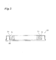
Fig. 3 is a side sectional view illustrating a cross-sectional structure of themicroplate 20 inFig. 1 ; -
Fig. 4 is a partially broken sectional view of anelectrical stimulator 16 inFig. 1 ; -
Fig. 5 is a flowchart illustrating operations of the cell observation system 1 at the time of measuring light from a sample S; -
Fig. 6 is a flowchart illustrating a procedure of processing for setting a position setting data table which is executed before the light measurement processing inFig. 5 ; -
Fig. 7 is a flowchart illustrating another operation of the cell observation system 1 inFig. 1 at the time of measuring light from the sample S; -
Fig. 8 is a flowchart illustrating a procedure of processing for setting the position setting data table which is executed at step S21 inFig. 7 ; -
Fig. 9 is a partially broken sectional view illustrating how adata analyzer 50 inFig. 1 controls the position of anelectrical stimulator 16; -
Fig. 10 is a partially broken sectional view illustrating how thedata analyzer 50 inFig. 1 controls the position of theelectrical stimulator 16; -
Fig. 11 is a sectional view illustrating structures ofelectrode pairs 17 in accordance with modified examples of the embodiment; -
Fig. 12 is a sectional view illustrating structures ofelectrode pairs 17 in accordance with modified examples of the embodiment; -
Fig. 13 is a front view illustrating a structure for controlling the position of theelectrical stimulator 16 in the cell observation system in accordance with a modified example of the present invention; -
Fig. 14 is a chart illustrating results of measurement of changes with time of average fluorescence intensities in respective analysis regions for two-dimensional optical images in 96wells 21 acquired when no electrical stimulation was performed in the cell observation system 1; -
Fig. 15 is a chart illustrating results of measurement of changes with time of average fluorescence intensities in respective analysis regions for two-dimensional optical images in 96wells 21 acquired when electrical stimulation was performed in the cell observation system 1; and -
Fig. 16 is a chart illustrating results of measurement corresponding to one well as extracted from the results of measurement inFigs. 14 and15 . - In the following, embodiments of the cell observation system, the electrical stimulation apparatus, and cell observation method in accordance with the present invention will be explained in detail with reference to the accompanying drawings. In the explanation of drawings, the same constituents will be referred to with the same signs while omitting their overlapping descriptions. The drawings are made for explanation and emphasize parts to be explained in particular. Therefore, members in the drawings are not always to scale.
-
Fig. 1 is a structural diagram schematically illustrating an embodiment of a cell observation system 1 in accordance with the present invention.Fig. 2 is a perspective view illustrating an example of the structure of amicroplate 20.Fig. 3 is a side sectional view illustrating a cross-sectional structure of themicroplate 20 inFig. 2 . The cell observation system 1 in accordance with this embodiment is a device, which uses themicroplate 20 as a sample case, for measuring fluorescence from a sample S placed at a measurement position P while being held by themicroplate 20. - The sample S includes a predetermined cell. An example of the predetermined cell is a neuron. The cell observation system, electrical stimulation apparatus, and cell observation method in this embodiment are employable not only for fluorescence measurement, but also for light measurement for measuring light in general, such as phosphorescence and luminescence, for example, emitted from samples. In the following, the structure of the cell observation system 1 will be explained.
- The cell observation system 1 illustrated in
Fig. 1 comprises adata acquisition device 10, a position controller (position control unit) 30, animaging controller 32, and adata analyzer 50. Thedata acquisition device 10 has adark box 15 for containing therewithin themicroplate 20 holding a cell subjected to fluorescence measurement and a movingimage acquisition unit 40 which is installed within thedark box 15 and used for measuring fluorescence from the sample S placed at the measurement position P. - As illustrated in
Figs. 2 and3 , themicroplate 20 used as the sample case in this embodiment is a planar member in which a plurality of wells (holding units) 21 are arranged in a two-dimensional array, which is constructed such that the sample S can be held in each of the plurality ofwells 21. In the structural example illustrated inFig. 2 ,8 × 12 = 96circular wells 21 are arranged in a two-dimensional array as a plurality ofwells 21. Examples of cross-sectional forms of thewells 21 include circles, ellipses, and rectangles. Themicroplate 20 has abottom face 22 formed from a material which can transmit therethrough excitation light, with which the sample S is irradiated for fluorescence measurement, and fluorescence emitted from the sample S. In general, it is sufficient for thebottom face 22 of themicroplate 20 in the cell observation system 1 to be formed from a material which can transmit therethrough light emitted from the sample S to be measured. - Within the
dark box 15, themicroplate 20 is mounted on a microplate holder (mounting unit) 11 having an opening for observing fluorescence. Amicroplate transfer mechanism 12 for transferring themicroplate 20 andmicroplate holder 11 in a predetermined direction (from the right side to the left side inFig. 1 ) within thedark box 15 is also installed within thedark box 15. - Installed on one side serving as the inlet side of the
dark box 15 in the transfer direction of themicroplate 20 in thetransfer mechanism 12 is aninlet microplate stocker 13 for stocking a predetermined number of (e.g., 25)microplates 20 holding the sample S before measurement. Installed on the other side serving as the outlet side of thedark box 15 in the transfer direction of themicroplate 20 is anoutlet microplate stocker 14 for stocking the microplates 20 after measurement. - In this structure, the
microplate 20 taken from theinlet microplate stocker 13 into thedark box 15 is held by themicroplate holder 11 and transferred by thetransfer mechanism 12. Themicroplate 20 is once stopped at the measurement position P, and light measurement necessary for the sample S held by themicroplate 20 is performed in this state. After the measurement is completed, themicroplate 20 is transferred by thetransfer mechanism 12 again, so as to be taken out to theoutlet microplate stocker 14. InFig. 1 , specific structures for taking in, transferring, and taking out themicroplate 20 are not depicted for thetransfer mechanism 12 andstockers - Installed above the measurement position P where the
microplate 20 and sample S are placed at the time of performing fluorescence measurement is an electrical stimulator (electrical stimulation apparatus) 16 to be inserted into thewells 21 of themicroplate 20 in order to generate an electric field in the sample S. Installed under the measurement position P is the moving image acquisition unit (light detection unit) 40 used for detecting fluorescence emitted through thebottom face 22 of the microplate 20 from the sample S contained within thewells 21. - The moving
image acquisition unit 40 is a moving image acquisition means which detects a two-dimensional optical image representing a two-dimensional optical intensity distribution of themicroplate 20 including light emitted from the sample S held within thewells 21 of themicroplate 20 and acquires moving image data of the two-dimensional optical image. The two-dimensional optical image to be detected may be an optical intensity distribution including light emitted from the sample S held within at least onewell 21. The movingimage acquisition unit 40 is constituted by animaging device 45, a light-guidingoptical system 41, anoptical filter unit 42, and anexcitation light source 43. Theimaging device 45 has a two-dimensional pixel structure in which a plurality of pixels are arranged two-dimensionally and detects a fluorescence image which is a two-dimensional light detection image caused by the fluorescence emitted from the sample S. As theimaging device 45, a highly sensitive CCD camera or CMOS imaging camera can be used, for example. If necessary, an image intensifier, a relay lens, and the like may be placed in front of the camera, so as to construct the movingimage acquisition unit 40. Theimage acquisition unit 40, which may acquire still images, has a function as an image acquisition unit for acquiring a moving image and/or a still image. - The light-guiding
optical system 41 is installed between the measurement position P where themicroplate 20 is placed and theimaging device 45. The light-guidingoptical system 41 is an optical system which guides to the imaging device 45 a two-dimensional optical image of themicroplate 20 holding the sample S in each of the plurality ofwells 21 as seen from thebottom face 22 side. A specific structure of the light-guidingoptical system 41 may be constructed as appropriate by optical elements which can achieve necessary functions (e.g., condensing function and optical image reducing function) according to the structures of themicroplate 20 andimaging device 45 and the like. An example of such optical elements is a tapered fiber (see Japanese Patent Application Laid-Open No.2001-188044 optical system 41 may also be constructed such as to use a light-guiding member having irregularities (see Japanese Patent Application Laid-Open Nos.2010-230397 2010-230396 - In
Fig. 1 , theoptical filter unit 42 adapted to place an optical filter onto the light-guiding path for fluorescence, switch it, and so forth when necessary is further installed between the light-guidingoptical system 41 andimaging device 45. However, theoptical filter unit 42 may be omitted when unnecessary. - The
excitation light source 43 is an excitation light supply means for supplying the sample S with excitation light for fluorescence measurement. A specific structure of theexcitation light source 43, an example of which is constituted by an illumination light source for supplying light and an optical filter unit for selecting or switching a wavelength of the excitation light, may be constructed as appropriate according to the kind of the sample S subjected to fluorescence measurement, the wavelength of the excitation light irradiating the sample S, and the like. Theexcitation light source 43 may be omitted when no supply of excitation light is necessary according to the kind of light measurement performed for the sample S. - In this embodiment, the light-guiding
optical system 41 is constructed as an optical system which can guide the two-dimensional optical image from themicroplate 20 and sample S to theimaging device 45 and the excitation light from theexcitation light source 43 to the sample S. For example, such an optical system can be constructed by using a dichroic mirror which transmits therethrough the fluorescence from themicroplate 20 and reflects the excitation light from theexcitation light source 43.Fig. 1 schematically illustrates optical paths of the fluorescence and excitation light in the light-guidingoptical system 41 with solid and broken lines, respectively. - The structure of the
electrical stimulator 16 will now be explained in detail.Fig. 4 is a partially broken sectional view of theelectrical stimulator 16 in a state inserted in themicroplate 20. Theelectrical stimulator 16 has a structure in which a plurality of electrode pairs 17 extending vertically toward themicroplate 20 are secured to abase part 18 so as to be arranged two-dimensionally. Specifically, the electrode pairs 17 are arranged two-dimensionally so as to correspond to the two dimensional array arrangement of the plurality ofwells 21 of themicroplate 20 and extend while facing thewells 21 of themicroplate 20. Eachelectrode pair 17 is constituted by anegative electrode 17a having a cylindrical form surrounding apositive electrode 17b with an open leading end and the rod-shaped (e.g., columnar)positive electrode 17b inserted into thenegative electrode 17a so as to be placed on the center axis of thenegative electrode 17a, while thenegative electrode 17a has an outer diameter smaller than the inner diameter of the well 21. The cylindrical form of thenegative electrode 17a may have either a circular or elliptical cross section. Theelectrode pair 17 also has such a structure that the leading end of the opening of thenegative electrode 17a on the well 21 side extends longer by a predetermined distance (e.g., within the range of at least 1 µm but not more than 1.0 mm) than the leading end of thepositive electrode 17b on the well 21 side, i.e., such a form that the distance from thebase part 18 to the leading end of thepositive electrode 17b is shorter by the predetermined distance than the distance from thebase part 18 to the leading end of thenegative electrode 17a. This allows the rod-shapedpositive electrode 17b to be contained within thenegative electrode 17a having the cylindrical form. This also forms a structure in which thepositive electrode 17b does not project from the leading end of thenegative electrode 17a, and the leading end of thenegative electrode 17a and that of thepositive electrode 17b are not flush with each other. Theelectrode pair 17 is not limited to one in which each of the negative andpositive electrodes - The
electrical stimulator 16 is also provided with ashifter mechanism 19 for supporting the electrode pairs 17 with thebase part 18 interposed therebetween. Theshifter mechanism 19, which is a driving mechanism for moving the electrode pairs 17 toward or away from the microplate 20 (in the Z direction inFig. 1 ) and in directions along thebottom face 22 of the microplate 20 (in directions along a plane including the X and Y axes inFig. 1 ), drives the electrode pairs 17 so as to place them into their opposingwells 21 when observing the sample S and separate them from within thewells 21 when the observation of the sample S is completed. - Coupled to thus constructed
data acquisition device 10 are the position controller (position control unit) 30 andimaging controller 32. Theposition controller 30 is electrically coupled to theshifter mechanism 19 and controls theshifter mechanism 19 such that the electrode pairs 17 are placed within thewells 21 of themicroplate 20 when starting light measurement of the sample S. Theposition controller 30 is also electrically coupled to the electrode pairs 17 so as to apply voltages to the negative andpositive electrodes positive electrodes imaging controller 32 controls the irradiation with the excitation light by theexcitation light source 43 and the capture of the two-dimensional fluorescence image in themicroplate 20 by theimaging device 45. - The data analyzer 50 is further coupled to the
position controller 30 andimaging controller 32. The data analyzer 50 is an analysis processing means which obtains through theimaging controller 32 the moving image data including the light detection image acquired by the movingimage acquisition unit 40 and performs analysis processing for the moving image data. The data analyzer 50 also controls the fluorescence measurement for the sample S in the cell observation system 1 by regulating operations of individual parts of thedata acquisition device 10 through theposition controller 30 and imaging controller 32 (as will be explained later in detail). InFig. 1 , adisplay device 61 for displaying measurement results and the like and aninput device 62 used for inputting data and instructions required for fluorescence measurement are coupled to thedata analyzer 50. - With reference to
Figs. 5 and6 , the cell observation method in accordance with this embodiment will now be set forth in detail while explaining operations by the cell observation system 1 at the time of measuring light from the sample S.Fig. 5 is a flowchart illustrating operations of the cell observation system 1 at the time of measuring light from the sample S, whileFig. 6 is a flowchart illustrating a procedure of processing for setting a position setting data table which is executed before the light measurement. - First, a trigger to start light measurement of a cell is inputted through the
input device 62, whereupon thedata analyzer 50 determines an analysis region in a two-dimensional optical image or still image included in the moving image data to be processed (step S01: analysis region determination step). The analysis region is set according to data in which a region including an area directly under thepositive electrode 17b in a reflected image of each well 21 has been stored beforehand. Subsequently, while being mounted on themicroplate holder 11, themicroplate 20 to be measured holding the sample S within themicroplate stocker 13 is transferred by themicroplate transfer mechanism 12 to the measurement position P within the dark box 15 (step S02: mounting step). Then, thedata analyzer 50 controls the position of theelectrical stimulator 16 by utilizing theshifter mechanism 19, so as to insert the leading ends of a plurality of electrode pairs 17 into their correspondingwells 21 of the microplate 20 (step S03: position control step). At this time, with reference to positional data corresponding to the kind of the currently in-use microplate 20 in a position setting data table stored beforehand, thedata analyzer 50 controls positions of the electrode pairs 17 such that the leading ends of thenegative electrodes 17a in the electrode pairs 17 come into contact with thebottom face 22 of themicroplate 20. This places thepositive electrodes 17b in a state where their leading ends are separated from the bottom faces of thewells 21 by about a predetermined distance (e.g., at least 1 µm but not more than 1.0 mm) corresponding to their difference in length from thenegative electrodes 17a. - Thereafter, the
data analyzer 50 controls theposition controller 30, so as to supply a voltage to the electrode pairs 17, thereby generating an electric field within thewells 21 of the microplate 20 (provision of electrical stimulation). In the state where the electric field is generated, the movingimage acquisition unit 40 detects a two-dimensional optical image of themicroplate 20 including fluorescence emitted from the sample S held within thewells 21, whereby thedata analyzer 50 acquires moving image data representing the two-dimensional optical image. The movingimage acquisition unit 40 has a frame rate which is set higher than the frequency at which the voltage is applied. For the two-dimensional optical image included in the acquired moving image data, thedata analyzer 50 analyzes the optical intensity in an analysis region which is set in a part of a region facing the electrode pairs 17 of themicroplate 20 on themicroplate holder 11, whereby analysis information concerning the sample S is obtained and outputted to the display device 61 (step S04: light detection step and information analysis step). Since the cell in the sample S is provided with a membrane potential-sensitive fluorescent dye, a change in the membrane potential accompanying opening/closing of an ion channel of the cell is seen as a change in intensity of fluorescence when electrical stimulation is applied thereto. As techniques for analyzing optical intensity in such an analysis region, those calculating the amplitude of change, ratio of change, peak period, number of peaks, peak time, rise time, fall time, peak fluctuation range, and the like in pixel values in the analysis region as evaluation values may be considered. - Referring now to
Fig. 6 , the procedure of processing for setting the position setting data table executed before the light measurement processing inFig. 5 will be explained. First, a plurality of kinds of microplates 20 each havingempty wells 21 are prepared within the microplate stocker 13 (step S11). Subsequently, while being mounted on themicroplate holder 11, one kind ofmicroplate 20 in the plurality of kinds of microplates 20 is transferred by themicroplate transfer mechanism 12 to the measurement position P within the dark box 15 (step S12). Thereafter, by using theinput device 62 of thedata analyzer 50, positional data for adjusting the position of theelectrical stimulator 16 is inputted to theposition controller 30, whereby the leading ends of the plurality of electrode pairs 17 are inserted into their correspondingwells 21 of the microplate 20 (step S13). Here, the position of theelectrical stimulator 16 is adjusted such that the leading end of thenegative electrode 17a of eachelectrode pair 17 comes into contact with thebottom face 22 of its opposing well 21. The positional data inputted by theinput device 62 at that time is stored into the position setting data table within thedata analyzer 50 in association with data concerning the kind of the microplate 20 (step S14). The processing of the foregoing steps S 12 toS 14 is repeated for all the kinds of microplates 20 (step S15), whereby the setting of the position setting data table is completed. - The cell observation system 1 may set the position setting data table in the middle of the light measurement operation for the sample S.
Fig. 7 illustrates the operation procedure of the cell observation system 1 at the time of measuring light from the sample S in such a case. - In this case, a trigger to start light measurement of a cell is inputted through the
input device 62, whereupon the position setting data table is set for adjusting the position of the electrical stimulator 16 (step S21). Subsequently, thedata analyzer 50 determines an analysis region in a two-dimensional optical image included in the moving image data to be processed (step S22: analysis region determination step). The analysis region is set according to data in which a region including an area directly under thepositive electrode 17b in the reflected image of each well 21 has been stored beforehand. Subsequently, while being mounted on themicroplate holder 11, themicroplate 20 to be measured holding the sample S within themicroplate stocker 13 is transferred by themicroplate transfer mechanism 12 to the measurement position P within the dark box 15 (step S23: mounting step). Then, thedata analyzer 50 controls the position of theelectrical stimulator 16 by utilizing theshifter mechanism 19, so as to insert the leading ends of the plurality of electrode pairs 17 into their correspondingwells 21 of the microplate 20 (step S24: position control step). At this time, with reference to the positional data of the position setting data table stored at the step S21, thedata analyzer 50 controls the positions of the electrode pairs 17 such that the leading ends of thenegative electrodes 17a of the electrode pairs 17 come into contact with thebottom face 22 of themicroplate 20. In practice, however, thewells 21 of themicroplate 20 hold the sample S, whereby the leading ends of thenegative electrodes 17a of the electrode pairs 17 may fail to come into contact with thebottom face 22 of themicroplate 20. This places thepositive electrodes 17b in a state where their leading ends are separated from the bottom faces of thewells 21 by about a predetermined distance (e.g., 1 µm to 1.0 mm) corresponding to their difference in length from thenegative electrodes 17a. - Thereafter, the
data analyzer 50 controls theposition controller 30, so as to supply voltages to the electrode pairs 17, thereby generating an electric field within thewells 21 of the microplate 20 (provision of electrical stimulation). In the state where the electric field is generated, the movingimage acquisition unit 40 detects a two-dimensional optical image of themicroplate 20 including fluorescence emitted from the sample S held within thewells 21, whereby thedata analyzer 50 acquires moving image data representing the two-dimensional optical image. For the two-dimensional optical image included in the acquired moving image data, thedata analyzer 50 analyzes the optical intensity in an analysis region which is set in a part of a region facing the electrode pairs 17 of themicroplate 20 on themicroplate holder 11, whereby analysis information concerning the sample S is obtained and outputted to the display device 61 (step S25: light detection step and information analysis step). - Referring now to
Fig. 8 , the procedure for setting the position setting data table executed at the step S21 inFig. 7 will be explained in detail. First, themicroplate 20 of the same kind as that of themicroplate 20 for measurement is prepared with itswells 21 empty within the microplate stocker 13 (step S31). Subsequently, while being mounted on themicroplate holder 11, themicroplate 20 is transferred by themicroplate transfer mechanism 12 to the measurement position P within the dark box 14 (step S32). Thereafter, by using theinput device 62 of thedata analyzer 50, positional data for adjusting the position of theelectrical stimulator 16 is inputted to theposition controller 30, whereby the leading ends of the plurality of electrode pairs 17 are inserted into their correspondingwells 21 of the microplate 20 (step S33). Here, the position of theelectrical stimulator 16 is adjusted such that the leading end of thenegative electrode 17a of eachelectrode pair 17 comes into contact with thebottom face 22 of its opposing well 21. The positional data inputted by theinput device 62 at that time is temporarily stored into the position setting data table within the data analyzer 50 (step S34) in order to be referred to at the step S24. The foregoing completes the setting of the position setting data table. - The above-mentioned position control of the
electrical stimulator 16 by thedata analyzer 50 at the step S03 (Fig. 5 ) and step S24 (Fig. 7 ) at the time when the cell observation system 1 measures light from the sample S will now be explained in detail. At the steps S03 and S24, as illustrated inFig. 9(a) , thedata analyzer 50 initially refers to the position setting data table, so as to move theelectrical stimulator 16 such that the positions of the leading ends of the plurality of electrode pairs 17 in directions along thebottom face 22 of the microplate 20 (directions along the X-Y plane) oppose theircorresponding wells 21. Then, thedata analyzer 50 further refers to the position setting data table, so as to move down theelectrical stimulator 16 in the Z direction until the leading ends of thenegative electrodes 17a of the electrode pairs 17 come into contact with the sample S reserved on the bottom faces of thewells 21 as illustrated inFig. 9(b) . Here, the positional data in the Z direction stored in the position setting data table is set in consideration of a minute length (e.g., a distance of at least 0.1 mm but not more than 0.2 mm) by which the sample S is held between the leading end of thenegative electrode 17a and the bottom face of the well 21. Thereafter, as illustrated inFig. 10 , thedata analyzer 50 moves down theelectrical stimulator 16 in the Z direction until the leading ends of thenegative electrodes 17a of the electrode pairs 17 come into contact with the bottom faces of thewells 21 by pressing the sample S reserved on the bottom faces. By thus controlling the positions of the electrode pairs 17 so as to press the bottom faces further by a distance of about at least 0.1 mm but not more than 0.2 mm from the positions acquired beforehand, even when the bottom faces of a plurality ofwells 21 are located at uneven positions, the leading ends of thenegative electrodes 17a can be brought into contact with the bottom faces of all thewells 21. - In the cell observation system 1 and cell observation method by the cell observation system 1 explained in the foregoing, the electrode pairs 17 including the positive and
negative electrodes wells 21 arranged in themicroplate 20, so as to make an electric field applicable to the sample S including a cell. Here, in the positive andnegative electrodes electrode pair 17, the leading end of thenegative electrode 17a extends longer than the leading end of thepositive electrode 17b, whereby the distance between the leading end of thepositive electrode 17b and the sample S can be stabilized at a predetermined distance (e.g., a distance of at least 1 µm but not more than 1 mm) by inserting theelectrode pair 17 into the well 21 such that the leading end of thenegative electrode 17a comes into contact with the sample S at the bottom part of the well 21. As a consequence, just providing a simple position control mechanism can stabilize the electric field applied from the electrode pairs 17 to the sample S, whereby uniform observation results concerning the sample S can be obtained. Such a structure brings thenegative electrodes 17a into contact with the sample S, whereby the sample S can be provided with an appropriate potential difference. - In the above-mentioned cell observation system 1, the
data analyzer 50 controls the positions of thenegative electrodes 17a such that their leading ends on the well 21 side come into contact with the bottom faces of thewells 21, which can stabilize the distance from the leading ends of thepositive electrodes 17b to the sample S at a predetermined distance, whereby just providing a simple position control mechanism can stabilize the electric field applied from the electrode pairs 17 to the sample S. - Since each
positive electrode 17b is a rod-shaped electrode, a region with a strong electric field on thebottom face 22 of the well 21 can be limited to an area near thepositive electrode 17b. This can yield highly sensitive observation results concerning the sample S. - The present invention is not limited to the above-mentioned embodiment.
- The structure of the
electrode pair 17 in theelectrical stimulator 16 is not limited to the coaxial form but can employ various forms. The data analyzer 50 can set the analysis region according to the structure of theelectrode pair 17. -
Figs. 11 and12 illustrate structures of electrode pairs 17 in accordance with modified examples of this embodiment. Each ofFigs. 11(a) to (d) andFigs. 12(a) and (b) illustrates cross sections of theelectrode pair 17 taken perpendicularly to and along the bottom face of themicroplate 20 on the right and left sides, respectively, together with the well 21. As these diagrams represent, theelectrode pair 17 can employ not only the coaxial form illustrated inFig. 11(a) , but also a structure of a combination of a rod-shapedpositive electrode 17b and a planarnegative electrode 17a facing it as illustrated inFig. 11(b) , a structure in which two rod-shapedpositive electrodes 17b face each other across a planarnegative electrode 17a in parallel as illustrated inFig. 11(c) , a structure in which two rod-shapedpositive electrodes 17b face each other across a rod-shapednegative electrode 17a in parallel as illustrated inFig. 11(d) , a structure of a combination of a rod-shapedpositive electrode 17b and a rod-shapednegative electrode 17a disposed in parallel therewith as illustrated inFig. 12(a) , and a combination of a rod-shapedpositive electrode 17b and two rod-shapednegative electrodes 17a opposing to it as illustrated inFig. 12(b) . A structure of a parallel electrode pair in which planar positive and negative electrodes are placed in parallel may also be employed. Each of these structures of theelectrode pair 17 is configured such that the leading end of thenegative electrode 17a on the well 21 side extends longer by a predetermined length than the leading end of thepositive electrode 17b on the well 21 side. - While the
data analyzer 50 controls the position of theelectrical stimulator 16 electronically with reference to the data stored therewithin in the above-mentioned cell observation system 1, members for positional control may be used for mechanical control.Fig. 13 illustrates a structure for controlling the position of theelectrical stimulator 16 in the cell observation system in accordance with a modified example of the present invention. A surface on the Z direction side of thebase part 18 of theelectrical stimulator 16 depicted in this drawing is provided with a button sensor (position detection sensor) 24 for positional detection, while an elongatedpositional reference member 25 fixed with respect to the dark box 15 (Fig. 1 ) is disposed on the Z direction side of thebutton sensor 24. Abuffer member 25 a is provided at a predetermined position in the Z direction of thepositional reference member 25 so as to oppose thebutton sensor 24. When thedata analyzer 50 moves theelectrical stimulator 16 in the Z direction such that the electrode pairs 17 thereof are inserted into thewells 21 of themicroplate 20 in this cell observation system, contact of thebutton sensor 24 with thebuffer member 25a of thepositional reference member 25 is detected, and the movement of theelectrical stimulator 16 is stopped in response to the detection. Here, an end face of thebuffer member 25a of thepositional reference member 25 is set to such a position of the leading end of thebutton sensor 24 that thenegative electrodes 17a of the electrode pairs 17 are in contact with the bottom faces of thewells 21, whereby the position of theelectrical stimulator 16 is controlled such that the leading ends of thenegative electrodes 17a of the electrode pairs 17 come into contact with the bottom faces of thewells 21. Providing thepositional reference member 25 with thebuffer member 25a can mitigate the initial pressure with which thebutton sensor 24 hits thepositional reference member 25, so that thebutton sensor 24 does not act immediately after the leading ends of thenegative electrode pairs 17a come into contact with the bottom faces of thewells 21, whereby theelectrical stimulator 16 stops moving after descending by a predetermined length (e.g., on the order of 0.1 mm to 0.2 mm). Therefore, even when the bottom faces of a plurality ofwells 21 are located at uneven positions, the leading ends of thenegative electrodes 17a can be brought into contact with the bottom faces of all thewells 21. - Though the above-mentioned embodiment is configured such that the
microplate 20 to be measured holding the sample S within themicroplate stocker 13 is transferred by themicroplate transfer mechanism 12 to the measurement position P within thedark box 15 while being mounted on themicroplate holder 11, a structure in which themicroplate 20 is manually placed at the measurement position P within thedark box 15 may also be employed. - In the cell observation system 1 and cell observation method by the cell observation system 1 in the above-mentioned embodiment, myocardial cells (cells constituting cardiac muscles) and skeletal muscle cells constituting muscles may be used as the sample S to be measured. The myocardial cells and skeletal muscle cells expand and contract as triggered by action potentials. Here, since calcium ions migrate through a cell membrane from the outside to inside of a cell or vice versa, dyeing calcium ions with a pigment reactive thereto and observing its fluorescence can show how the myocardial cells and skeletal muscle cells expand and contract. While muscle cells within organisms typically expand and contract with the aid of pacemaker cells which control action potentials, myocardial cells and skeletal muscle cells produced from stem cells such as iPS cells and ES cells may lack cells to become a pacemaker or fail to be controlled well. Even such muscle cells can be expanded and contracted when electrical stimulation is imparted thereto from the outside by using the cell observation system 1 so as to control action potentials. There have recently been increasing demands for evaluating drug discovery by using myocardial cells and skeletal muscle cells. In particular, this embodiment performing electrical stimulation from the outside is effective as a technique for evaluating various chemical compounds, since it not only enables usual pacing but also makes it possible to evaluate compounds whose efficacy depends on the beating rate and intentionally cause arrhythmia.
- An example using a muscle cell as a subject will now be explained.
- Employed as the sample S held within 96
wells 21 of themicroplate 20 is one in which a myocardial cell of a heart (ventricle) of a 1-to-4-day-old SD rat was cultivated to 2 × 10⁴ cells per well. Used as themicroplate 20 is one in which thewells 21 were coated with collagen I. The myocardial cell was dyed with a calcium dye (Cal520-AM). - At the position control step (
Fig. 5 : S03), thedata analyzer 50 controls the electrode pairs 17 so that they are placed within thewells 21 holding the myocardial cells. At the light detection step (Fig. 5 : S04) thereafter, a voltage is applied to the electrode pairs 17 under the control of thedata analyzer 50, so as to impart electrical stimulation to the myocardial cells within thewells 21. Specifically, a pulse voltage in the form of a rectangular wave having a peak value of 5 V and a time width of 5 ms is applied for 5 sec at a repetition frequency of 1 Hz. The repetition frequency is preferably set within the range of 0.5 Hz to 2 Hz. At the same time, thedata analyzer 50 acquires moving image data representing a two-dimensional optical image of themicroplate 20 for 31 ms per frame, i.e., at a frame rate of 30 frames/sec, while the voltage is applied to the electrode pairs 17. Then, thedata analyzer 50 analyzes fluorescence intensity in the analysis region by using the acquired moving image data. -
Figs. 14 and15 illustrate measurement results of changes with time of average fluorescence intensity in the analysis region of the two-dimensional optical image in each of 96wells 21 acquired in this example without and with the electrical stimulation by the pulse voltage, respectively. The measurement results for therespective wells 21 are arranged two-dimensionally in columns 1 to 12 and lines A to H. It is seen from the measurement results that, when no pacing with the pulse voltage is performed, cells to become a pacemaker appear to act in a part of the 96 wells so as to change the fluorescence intensity, but there are wells where pacemakers do not work at all. When pacing with the pulse voltage is performed, on the other hand, changes in fluorescence intensity are observed in all of the 96 wells. -
Fig. 16 illustrates the measurement results of the well atcolumn 3, line B as extracted from those inFigs. 14 and15 , in which (a) and (b) show the results without and with the electrical stimulation, respectively. Thus, while irregular peaks are observed without pacing, periodical fluorescence peaks are seen in response to timings T1 of electrical stimulation when pacing is performed, which verifies that the above-mentioned cell observation system and cell observation method are effective for pacing myocardial cells. - By randomly applying a rectangular-wave pulse voltage to myocardial cells, the above-mentioned cell observation system and cell observation method are effective in observation in an arrhythmic state.
- Preferably, in the above-mentioned cell observation system, the position control unit controls the position such that the leading end of the negative electrode on the holding unit side comes into contact with the bottom face of the holding unit. Employing such a structure can stabilize the distance between the leading end of the positive electrode and sample at a predetermined distance. As a consequence, just providing a simple position control mechanism can stabilize the electric field applied from the electrode pair to the sample.
- Preferably, the positive electrode is a rod-shaped electrode. Providing such a rod-shaped electrode can limit a region with a strong electric field on the bottom face of the well to an area near the positive electrode. This can yield highly sensitive observation results concerning the sample.
- The negative electrode may be a cylindrical electrode surrounding the positive electrode, a planar electrode facing the positive electrode, or a rod-shaped electrode placed in parallel with the positive electrode.
- Preferably, the leading end of the negative electrode extends longer than the leading end of the positive electrode by a length of at least 1 µm but not more than 1.0 mm. This can further stabilize the electric field applied from the electrode pairs to the sample.
- Preferably, the position control step controls the position such that the leading end of the negative electrode on the holding unit side comes into contact with the bottom face of the holding unit. This enables simple positional control to stabilize the positional relationship between the electrode pair and sample.
- The present invention is used for a cell observation system, electrical stimulation apparatus, and cell observation method for observing a reaction of a sample including a cell in response to electrical stimulation and, with a simple structure, can stabilize an electric field applied to a cell within a plurality of arranged holding units.
- 1: cell observation system; 11: microplate holder (mounting unit); 16: electrical stimulator; 17: electrode pair; 17a: negative electrode; 17b: positive electrode; 20: microplate (sample case); 21: well (holding unit); 22: bottom face; 30: position controller (position control unit); 50: data analyzer (position control unit); P: measurement position; S: sample.
Claims (12)
- A cell observation system for observing a cell held by a sample case comprising a plurality of holding units arranged therein for holding a sample including the cell, the cell observation system comprising:a mounting unit for mounting the sample case;an electrical stimulator arranged with a plurality of electrode pairs comprising a positive electrode and a negative electrode; anda position control unit for controlling a position of the electrical stimulator so as to place the electrode pairs within the holding units of the sample case;wherein a leading end of the negative electrode on the holding unit side extends longer than a leading end of the positive electrode on the holding unit side.
- The cell observation system according to claim 1, wherein the position control unit controls the position such that the leading end of the negative electrode on the holding unit side comes into contact with a bottom face of the holding unit.
- The cell observation system according to claim 1 or 2, wherein the positive electrode comprises a rod-shaped electrode.
- The cell observation system according to claim 3, wherein the negative electrode comprises a cylindrical electrode surrounding the positive electrode.
- The cell observation system according to claim 3, wherein the negative electrode comprises a planar electrode facing the positive electrode.
- The cell observation system according to claim 3, wherein the negative electrode comprises a rod-shaped electrode placed in parallel with the positive electrode.
- The cell observation system according to one of claims 1 to 6, wherein the position control unit performs such control as to place the electrode pairs within the holding units holding the sample including a muscle cell, and
analyzes the optical intensity of an analysis region in a state where a pulse voltage is repeatedly applied to the electrode pairs. - An electrical stimulation apparatus, inserted into a sample case comprising a plurality of holding units arranged therein for holding a sample including a cell, for applying a voltage to the cell,
the electrical stimulation apparatus comprising:a plurality of electrode pairs, arranged therein, comprising a positive electrode and a negative electrode, the negative electrode comprising a leading end extending longer than a leading end of the positive electrode. - The electrical stimulation apparatus according to claim 8, wherein the leading end of the negative electrode extends longer than the leading end of the positive electrode by a length of at least 1 µm but not more than 1.0 mm.
- A cell observation method for observing a cell held by a sample case comprising a plurality of holding units arranged therein for holding a sample including the cell, the method comprising:a mounting step of mounting the sample case on a mounting unit; anda position control step of controlling a position of an electrical stimulator arranged with a plurality of electrode pairs comprising a positive electrode and a negative electrode so as to place the electrode pairs within the holding units of the sample case;wherein a leading end of the negative electrode on the holding unit side extends longer than a leading end of the positive electrode on the holding unit side.
- The cell observation method according to claim 10, wherein the position control step controls the position such that the leading end of the negative electrode on the holding unit side comes into contact with a bottom face of the holding unit.
- The cell observation method according to claim 10 or 11, wherein the position control step performs such control as to place the electrode pairs within the holding units holding the sample including a muscle cell, and
analyzes the optical intensity of an analysis region in a state where a pulse voltage is repeatedly applied to the electrode pairs.
Applications Claiming Priority (2)
| Application Number | Priority Date | Filing Date | Title |
|---|---|---|---|
| JP2012235891 | 2012-10-25 | ||
| PCT/JP2013/078717 WO2014065330A1 (en) | 2012-10-25 | 2013-10-23 | Cell observation device, electrical stimulation device, and cell observation method |
Publications (3)
| Publication Number | Publication Date |
|---|---|
| EP2913390A1 true EP2913390A1 (en) | 2015-09-02 |
| EP2913390A4 EP2913390A4 (en) | 2016-06-29 |
| EP2913390B1 EP2913390B1 (en) | 2020-12-09 |
Family
ID=50544705
Family Applications (1)
| Application Number | Title | Priority Date | Filing Date |
|---|---|---|---|
| EP13849414.1A Active EP2913390B1 (en) | 2012-10-25 | 2013-10-23 | Electrical stimulation device, cell observation device and cell observation method |
Country Status (4)
| Country | Link |
|---|---|
| US (1) | US9778189B2 (en) |
| EP (1) | EP2913390B1 (en) |
| JP (2) | JP5778354B2 (en) |
| WO (1) | WO2014065330A1 (en) |
Families Citing this family (2)
| Publication number | Priority date | Publication date | Assignee | Title |
|---|---|---|---|---|
| JP6159486B2 (en) * | 2014-06-12 | 2017-07-05 | アクシオン バイオシステムズ, インコーポレイテッド | Multiwell microelectrode array with optical stimulation |
| JP7097800B2 (en) * | 2018-11-27 | 2022-07-08 | 株式会社Screenホールディングス | Electrode holding member |
Family Cites Families (25)
| Publication number | Priority date | Publication date | Assignee | Title |
|---|---|---|---|---|
| CA1276972C (en) * | 1986-10-22 | 1990-11-27 | David S. Strong | Multi-cell metal/air battery |
| EP0581983B1 (en) * | 1992-08-04 | 1996-10-23 | Hewlett-Packard GmbH | Apparatus for performing capillary electrophoresis |
| DK0980523T3 (en) * | 1997-05-01 | 2007-04-30 | Sophion Bioscience As | Device for automatic electrode placement |
| JP4327970B2 (en) | 1999-12-28 | 2009-09-09 | 浜松ホトニクス株式会社 | Luminescence measuring apparatus and fluorescence measuring apparatus |
| AU2001275881B2 (en) | 2000-07-10 | 2006-04-06 | Vertex Pharmaceuticals (San Diego) Llc | Ion channel assay methods |
| US7615356B2 (en) | 2000-07-10 | 2009-11-10 | Vertex Pharmaceuticals (San Diego) Llc | Ion channel assay methods |
| JP2004537713A (en) * | 2000-12-01 | 2004-12-16 | セテク コーポレイション | High-throughput capillary electrophoresis system |
| CA2453489A1 (en) | 2001-07-12 | 2003-01-23 | Merck & Co., Inc. | Electrical field stimulation of eukaryotic cells |
| US20060127365A1 (en) * | 2002-05-31 | 2006-06-15 | Victor Nurcombe | Method of cell therapy using fused cell hybrids |
| JP2004147517A (en) | 2002-10-29 | 2004-05-27 | Hitachi Ltd | Apparatus for transfecting gene |
| US8658349B2 (en) * | 2006-07-13 | 2014-02-25 | Seahorse Bioscience | Cell analysis apparatus and method |
| ES2294757T3 (en) * | 2004-03-15 | 2008-04-01 | Amaxa Ag | CONTAINER AND DEVICE FOR GENERATING ELECTRIC FIELDS IN INDIVIDUAL REACTION SPACES. |
| US20050277183A1 (en) * | 2004-05-18 | 2005-12-15 | Ronald Lee | Electroporation cuvette |
| JP4611143B2 (en) | 2005-08-01 | 2011-01-12 | 矢崎総業株式会社 | Liquid level sensor |
| JP2007135947A (en) * | 2005-11-21 | 2007-06-07 | Fujifilm Corp | Optical probe and optical tomographic imaging system |
| US20110163744A1 (en) * | 2008-04-21 | 2011-07-07 | National University Corporation Nagoya University | Cellular tissue magnetic signal detecting apparatus |
| US20120053084A1 (en) | 2008-09-04 | 2012-03-01 | Galenea Corp. | Synaptic vesicle cycling assays and systems |
| JP5219898B2 (en) | 2009-03-26 | 2013-06-26 | 浜松ホトニクス株式会社 | Light irradiation device and light measurement device |
| JP5219899B2 (en) | 2009-03-26 | 2013-06-26 | 浜松ホトニクス株式会社 | Light irradiation device and light measurement device |
| JP2012522518A (en) * | 2009-04-03 | 2012-09-27 | ザ リージェンツ オブ ザ ユニバーシティ オブ カリフォルニア | Method and apparatus for sorting cells and bioparticles |
| US9091151B2 (en) * | 2009-11-19 | 2015-07-28 | Halliburton Energy Services, Inc. | Downhole optical radiometry tool |
| US8873027B2 (en) * | 2010-04-23 | 2014-10-28 | Hamamatsu Photonics K.K. | Cell observation device and cell observation method |
| JP5457262B2 (en) * | 2010-04-23 | 2014-04-02 | 浜松ホトニクス株式会社 | Membrane potential change detection apparatus and membrane potential change detection method |
| WO2012066747A1 (en) * | 2010-11-17 | 2012-05-24 | パナソニック株式会社 | Device for measuring microbial count |
| US11169086B2 (en) * | 2015-04-10 | 2021-11-09 | Blaze Metrics, LLC | System and method for simultaneously performing multiple optical analyses of liquids and particles in a fluid |
-
2013
- 2013-10-23 JP JP2014543328A patent/JP5778354B2/en active Active
- 2013-10-23 WO PCT/JP2013/078717 patent/WO2014065330A1/en active Application Filing
- 2013-10-23 US US14/437,964 patent/US9778189B2/en active Active
- 2013-10-23 EP EP13849414.1A patent/EP2913390B1/en active Active
-
2015
- 2015-06-03 JP JP2015113173A patent/JP6190420B2/en active Active
Also Published As
| Publication number | Publication date |
|---|---|
| JP5778354B2 (en) | 2015-09-16 |
| JPWO2014065330A1 (en) | 2016-09-08 |
| EP2913390B1 (en) | 2020-12-09 |
| EP2913390A4 (en) | 2016-06-29 |
| JP2015163082A (en) | 2015-09-10 |
| US20150276599A1 (en) | 2015-10-01 |
| US9778189B2 (en) | 2017-10-03 |
| JP6190420B2 (en) | 2017-08-30 |
| WO2014065330A1 (en) | 2014-05-01 |
Similar Documents
| Publication | Publication Date | Title |
|---|---|---|
| US9772322B2 (en) | Cell observation device, and cell observation method | |
| US20220119756A1 (en) | Cell observation device, electrostimulation device, and cell observation method | |
| US20140349332A1 (en) | Method and device for examining myocardial toxicity and evaluating cardiomyocyte | |
| US9778189B2 (en) | Cell observation device, electrical stimulation device, and cell observation method | |
| JP2864130B2 (en) | Image processing device | |
| EP1512963B1 (en) | Fluorescence lifetime distribution image measuring system and its measuring method | |
| DE102012100098B4 (en) | Method for recording temporal changes in the time function of an optical signal with spatial resolution along a line in space | |
| Daily et al. | High-throughput phenotyping of human induced pluripotent stem cell-derived cardiomyocytes and neurons using electric field stimulation and high-speed fluorescence imaging | |
| US7041951B2 (en) | Method and apparatus for investigating layers of tissues in living animals using a microscope | |
| DE3915421A1 (en) | Periodic, alternating monochromatisation of polychromatic light beam - is used esp. for top illumination microscopy, and has dichroitical colour dividers, chopper and interference filters | |
| US20160274081A1 (en) | Cell observation apparatus | |
| Kampa et al. | Measuring neuronal population activity using 3D laser scanning | |
| EP3458844A1 (en) | Method and device for measuring process parameters in liquid cultures | |
| KR20150094317A (en) | Optoelectric cell stimulator | |
| JP2003075731A (en) | High-speed photographing device |
Legal Events
| Date | Code | Title | Description |
|---|---|---|---|
| PUAI | Public reference made under article 153(3) epc to a published international application that has entered the european phase |
Free format text: ORIGINAL CODE: 0009012 |
|
| 17P | Request for examination filed |
Effective date: 20150427 |
|
| AK | Designated contracting states |
Kind code of ref document: A1 Designated state(s): AL AT BE BG CH CY CZ DE DK EE ES FI FR GB GR HR HU IE IS IT LI LT LU LV MC MK MT NL NO PL PT RO RS SE SI SK SM TR |
|
| AX | Request for extension of the european patent |
Extension state: BA ME |
|
| DAX | Request for extension of the european patent (deleted) | ||
| RA4 | Supplementary search report drawn up and despatched (corrected) |
Effective date: 20160531 |
|
| RIC1 | Information provided on ipc code assigned before grant |
Ipc: G01N 15/10 20060101ALI20160524BHEP Ipc: G01N 15/14 20060101ALI20160524BHEP Ipc: A61N 1/32 20060101ALN20160524BHEP Ipc: C12M 1/34 20060101AFI20160524BHEP Ipc: G01N 33/487 20060101ALN20160524BHEP Ipc: C12Q 1/02 20060101ALI20160524BHEP |
|
| STAA | Information on the status of an ep patent application or granted ep patent |
Free format text: STATUS: EXAMINATION IS IN PROGRESS |
|
| 17Q | First examination report despatched |
Effective date: 20190709 |
|
| RIC1 | Information provided on ipc code assigned before grant |
Ipc: G01N 15/10 20060101ALI20200629BHEP Ipc: C12Q 1/02 20060101ALI20200629BHEP Ipc: G01N 15/14 20060101ALI20200629BHEP Ipc: C12M 1/34 20060101AFI20200629BHEP Ipc: A61N 1/32 20060101ALN20200629BHEP Ipc: G01N 33/487 20060101ALN20200629BHEP |
|
| RIC1 | Information provided on ipc code assigned before grant |
Ipc: A61N 1/32 20060101ALN20200706BHEP Ipc: G01N 15/14 20060101ALI20200706BHEP Ipc: G01N 15/10 20060101ALI20200706BHEP Ipc: G01N 33/487 20060101ALN20200706BHEP Ipc: C12Q 1/02 20060101ALI20200706BHEP Ipc: C12M 1/34 20060101AFI20200706BHEP |
|
| RIC1 | Information provided on ipc code assigned before grant |
Ipc: G01N 15/10 20060101ALI20200710BHEP Ipc: G01N 15/14 20060101ALI20200710BHEP Ipc: A61N 1/32 20060101ALN20200710BHEP Ipc: C12M 1/34 20060101AFI20200710BHEP Ipc: G01N 33/487 20060101ALN20200710BHEP Ipc: C12Q 1/02 20060101ALI20200710BHEP |
|
| GRAP | Despatch of communication of intention to grant a patent |
Free format text: ORIGINAL CODE: EPIDOSNIGR1 |
|
| STAA | Information on the status of an ep patent application or granted ep patent |
Free format text: STATUS: GRANT OF PATENT IS INTENDED |
|
| INTG | Intention to grant announced |
Effective date: 20200901 |
|
| GRAS | Grant fee paid |
Free format text: ORIGINAL CODE: EPIDOSNIGR3 |
|
| GRAA | (expected) grant |
Free format text: ORIGINAL CODE: 0009210 |
|
| STAA | Information on the status of an ep patent application or granted ep patent |
Free format text: STATUS: THE PATENT HAS BEEN GRANTED |
|
| AK | Designated contracting states |
Kind code of ref document: B1 Designated state(s): AL AT BE BG CH CY CZ DE DK EE ES FI FR GB GR HR HU IE IS IT LI LT LU LV MC MK MT NL NO PL PT RO RS SE SI SK SM TR |
|
| REG | Reference to a national code |
Ref country code: GB Ref legal event code: FG4D |
|
| REG | Reference to a national code |
Ref country code: AT Ref legal event code: REF Ref document number: 1343482 Country of ref document: AT Kind code of ref document: T Effective date: 20201215 Ref country code: CH Ref legal event code: EP |
|
| REG | Reference to a national code |
Ref country code: DE Ref legal event code: R096 Ref document number: 602013074682 Country of ref document: DE |
|
| REG | Reference to a national code |
Ref country code: IE Ref legal event code: FG4D |
|
| REG | Reference to a national code |
Ref country code: CH Ref legal event code: NV Representative=s name: SERVOPATENT GMBH, CH |
|
| PG25 | Lapsed in a contracting state [announced via postgrant information from national office to epo] |
Ref country code: NO Free format text: LAPSE BECAUSE OF FAILURE TO SUBMIT A TRANSLATION OF THE DESCRIPTION OR TO PAY THE FEE WITHIN THE PRESCRIBED TIME-LIMIT Effective date: 20210309 Ref country code: FI Free format text: LAPSE BECAUSE OF FAILURE TO SUBMIT A TRANSLATION OF THE DESCRIPTION OR TO PAY THE FEE WITHIN THE PRESCRIBED TIME-LIMIT Effective date: 20201209 Ref country code: RS Free format text: LAPSE BECAUSE OF FAILURE TO SUBMIT A TRANSLATION OF THE DESCRIPTION OR TO PAY THE FEE WITHIN THE PRESCRIBED TIME-LIMIT Effective date: 20201209 Ref country code: GR Free format text: LAPSE BECAUSE OF FAILURE TO SUBMIT A TRANSLATION OF THE DESCRIPTION OR TO PAY THE FEE WITHIN THE PRESCRIBED TIME-LIMIT Effective date: 20210310 |
|
| REG | Reference to a national code |
Ref country code: AT Ref legal event code: MK05 Ref document number: 1343482 Country of ref document: AT Kind code of ref document: T Effective date: 20201209 |
|
| PG25 | Lapsed in a contracting state [announced via postgrant information from national office to epo] |
Ref country code: SE Free format text: LAPSE BECAUSE OF FAILURE TO SUBMIT A TRANSLATION OF THE DESCRIPTION OR TO PAY THE FEE WITHIN THE PRESCRIBED TIME-LIMIT Effective date: 20201209 Ref country code: LV Free format text: LAPSE BECAUSE OF FAILURE TO SUBMIT A TRANSLATION OF THE DESCRIPTION OR TO PAY THE FEE WITHIN THE PRESCRIBED TIME-LIMIT Effective date: 20201209 Ref country code: BG Free format text: LAPSE BECAUSE OF FAILURE TO SUBMIT A TRANSLATION OF THE DESCRIPTION OR TO PAY THE FEE WITHIN THE PRESCRIBED TIME-LIMIT Effective date: 20210309 |
|
| REG | Reference to a national code |
Ref country code: NL Ref legal event code: MP Effective date: 20201209 |
|
| PG25 | Lapsed in a contracting state [announced via postgrant information from national office to epo] |
Ref country code: NL Free format text: LAPSE BECAUSE OF FAILURE TO SUBMIT A TRANSLATION OF THE DESCRIPTION OR TO PAY THE FEE WITHIN THE PRESCRIBED TIME-LIMIT Effective date: 20201209 Ref country code: HR Free format text: LAPSE BECAUSE OF FAILURE TO SUBMIT A TRANSLATION OF THE DESCRIPTION OR TO PAY THE FEE WITHIN THE PRESCRIBED TIME-LIMIT Effective date: 20201209 |
|
| REG | Reference to a national code |
Ref country code: LT Ref legal event code: MG9D |
|
| PG25 | Lapsed in a contracting state [announced via postgrant information from national office to epo] |
Ref country code: LT Free format text: LAPSE BECAUSE OF FAILURE TO SUBMIT A TRANSLATION OF THE DESCRIPTION OR TO PAY THE FEE WITHIN THE PRESCRIBED TIME-LIMIT Effective date: 20201209 Ref country code: SK Free format text: LAPSE BECAUSE OF FAILURE TO SUBMIT A TRANSLATION OF THE DESCRIPTION OR TO PAY THE FEE WITHIN THE PRESCRIBED TIME-LIMIT Effective date: 20201209 Ref country code: PT Free format text: LAPSE BECAUSE OF FAILURE TO SUBMIT A TRANSLATION OF THE DESCRIPTION OR TO PAY THE FEE WITHIN THE PRESCRIBED TIME-LIMIT Effective date: 20210409 Ref country code: RO Free format text: LAPSE BECAUSE OF FAILURE TO SUBMIT A TRANSLATION OF THE DESCRIPTION OR TO PAY THE FEE WITHIN THE PRESCRIBED TIME-LIMIT Effective date: 20201209 Ref country code: SM Free format text: LAPSE BECAUSE OF FAILURE TO SUBMIT A TRANSLATION OF THE DESCRIPTION OR TO PAY THE FEE WITHIN THE PRESCRIBED TIME-LIMIT Effective date: 20201209 Ref country code: CZ Free format text: LAPSE BECAUSE OF FAILURE TO SUBMIT A TRANSLATION OF THE DESCRIPTION OR TO PAY THE FEE WITHIN THE PRESCRIBED TIME-LIMIT Effective date: 20201209 Ref country code: EE Free format text: LAPSE BECAUSE OF FAILURE TO SUBMIT A TRANSLATION OF THE DESCRIPTION OR TO PAY THE FEE WITHIN THE PRESCRIBED TIME-LIMIT Effective date: 20201209 |
|
| PG25 | Lapsed in a contracting state [announced via postgrant information from national office to epo] |
Ref country code: PL Free format text: LAPSE BECAUSE OF FAILURE TO SUBMIT A TRANSLATION OF THE DESCRIPTION OR TO PAY THE FEE WITHIN THE PRESCRIBED TIME-LIMIT Effective date: 20201209 Ref country code: AT Free format text: LAPSE BECAUSE OF FAILURE TO SUBMIT A TRANSLATION OF THE DESCRIPTION OR TO PAY THE FEE WITHIN THE PRESCRIBED TIME-LIMIT Effective date: 20201209 |
|
| REG | Reference to a national code |
Ref country code: DE Ref legal event code: R097 Ref document number: 602013074682 Country of ref document: DE |
|
| PG25 | Lapsed in a contracting state [announced via postgrant information from national office to epo] |
Ref country code: IS Free format text: LAPSE BECAUSE OF FAILURE TO SUBMIT A TRANSLATION OF THE DESCRIPTION OR TO PAY THE FEE WITHIN THE PRESCRIBED TIME-LIMIT Effective date: 20210409 |
|
| PLBE | No opposition filed within time limit |
Free format text: ORIGINAL CODE: 0009261 |
|
| STAA | Information on the status of an ep patent application or granted ep patent |
Free format text: STATUS: NO OPPOSITION FILED WITHIN TIME LIMIT |
|
| PG25 | Lapsed in a contracting state [announced via postgrant information from national office to epo] |
Ref country code: AL Free format text: LAPSE BECAUSE OF FAILURE TO SUBMIT A TRANSLATION OF THE DESCRIPTION OR TO PAY THE FEE WITHIN THE PRESCRIBED TIME-LIMIT Effective date: 20201209 Ref country code: IT Free format text: LAPSE BECAUSE OF FAILURE TO SUBMIT A TRANSLATION OF THE DESCRIPTION OR TO PAY THE FEE WITHIN THE PRESCRIBED TIME-LIMIT Effective date: 20201209 |
|
| 26N | No opposition filed |
Effective date: 20210910 |
|
| PG25 | Lapsed in a contracting state [announced via postgrant information from national office to epo] |
Ref country code: ES Free format text: LAPSE BECAUSE OF FAILURE TO SUBMIT A TRANSLATION OF THE DESCRIPTION OR TO PAY THE FEE WITHIN THE PRESCRIBED TIME-LIMIT Effective date: 20201209 Ref country code: DK Free format text: LAPSE BECAUSE OF FAILURE TO SUBMIT A TRANSLATION OF THE DESCRIPTION OR TO PAY THE FEE WITHIN THE PRESCRIBED TIME-LIMIT Effective date: 20201209 Ref country code: SI Free format text: LAPSE BECAUSE OF FAILURE TO SUBMIT A TRANSLATION OF THE DESCRIPTION OR TO PAY THE FEE WITHIN THE PRESCRIBED TIME-LIMIT Effective date: 20201209 |
|
| PG25 | Lapsed in a contracting state [announced via postgrant information from national office to epo] |
Ref country code: IS Free format text: LAPSE BECAUSE OF FAILURE TO SUBMIT A TRANSLATION OF THE DESCRIPTION OR TO PAY THE FEE WITHIN THE PRESCRIBED TIME-LIMIT Effective date: 20210409 |
|
| REG | Reference to a national code |
Ref country code: BE Ref legal event code: MM Effective date: 20211031 |
|
| PG25 | Lapsed in a contracting state [announced via postgrant information from national office to epo] |
Ref country code: MC Free format text: LAPSE BECAUSE OF FAILURE TO SUBMIT A TRANSLATION OF THE DESCRIPTION OR TO PAY THE FEE WITHIN THE PRESCRIBED TIME-LIMIT Effective date: 20201209 |
|
| PG25 | Lapsed in a contracting state [announced via postgrant information from national office to epo] |
Ref country code: LU Free format text: LAPSE BECAUSE OF NON-PAYMENT OF DUE FEES Effective date: 20211023 Ref country code: BE Free format text: LAPSE BECAUSE OF NON-PAYMENT OF DUE FEES Effective date: 20211031 |
|
| PG25 | Lapsed in a contracting state [announced via postgrant information from national office to epo] |
Ref country code: IE Free format text: LAPSE BECAUSE OF NON-PAYMENT OF DUE FEES Effective date: 20211023 |
|
| PG25 | Lapsed in a contracting state [announced via postgrant information from national office to epo] |
Ref country code: HU Free format text: LAPSE BECAUSE OF FAILURE TO SUBMIT A TRANSLATION OF THE DESCRIPTION OR TO PAY THE FEE WITHIN THE PRESCRIBED TIME-LIMIT; INVALID AB INITIO Effective date: 20131023 |
|
| P01 | Opt-out of the competence of the unified patent court (upc) registered |
Effective date: 20230509 |
|
| PG25 | Lapsed in a contracting state [announced via postgrant information from national office to epo] |
Ref country code: CY Free format text: LAPSE BECAUSE OF FAILURE TO SUBMIT A TRANSLATION OF THE DESCRIPTION OR TO PAY THE FEE WITHIN THE PRESCRIBED TIME-LIMIT Effective date: 20201209 |
|
| PGFP | Annual fee paid to national office [announced via postgrant information from national office to epo] |
Ref country code: GB Payment date: 20230831 Year of fee payment: 11 |
|
| PGFP | Annual fee paid to national office [announced via postgrant information from national office to epo] |
Ref country code: FR Payment date: 20230911 Year of fee payment: 11 |
|
| PGFP | Annual fee paid to national office [announced via postgrant information from national office to epo] |
Ref country code: DE Payment date: 20230830 Year of fee payment: 11 Ref country code: CH Payment date: 20231102 Year of fee payment: 11 |