EP2912362B1 - Mount, and set comprising a mount - Google Patents
Mount, and set comprising a mount Download PDFInfo
- Publication number
- EP2912362B1 EP2912362B1 EP13824478.5A EP13824478A EP2912362B1 EP 2912362 B1 EP2912362 B1 EP 2912362B1 EP 13824478 A EP13824478 A EP 13824478A EP 2912362 B1 EP2912362 B1 EP 2912362B1
- Authority
- EP
- European Patent Office
- Prior art keywords
- mount
- holder
- elements
- slot
- clamp
- Prior art date
- Legal status (The legal status is an assumption and is not a legal conclusion. Google has not performed a legal analysis and makes no representation as to the accuracy of the status listed.)
- Active
Links
- 238000013016 damping Methods 0.000 claims description 19
- XAGFODPZIPBFFR-UHFFFAOYSA-N aluminium Chemical compound [Al] XAGFODPZIPBFFR-UHFFFAOYSA-N 0.000 claims description 2
- 229910052782 aluminium Inorganic materials 0.000 claims description 2
- 239000003086 colorant Substances 0.000 claims description 2
- 239000004411 aluminium Substances 0.000 claims 1
- 239000004033 plastic Substances 0.000 description 6
- 229920003023 plastic Polymers 0.000 description 6
- 239000000463 material Substances 0.000 description 2
- 230000009471 action Effects 0.000 description 1
- 230000006978 adaptation Effects 0.000 description 1
- 239000000853 adhesive Substances 0.000 description 1
- 230000001070 adhesive effect Effects 0.000 description 1
- 230000008901 benefit Effects 0.000 description 1
- 230000008859 change Effects 0.000 description 1
- 230000007423 decrease Effects 0.000 description 1
- 230000001419 dependent effect Effects 0.000 description 1
- 230000003993 interaction Effects 0.000 description 1
- 230000007246 mechanism Effects 0.000 description 1
- 229920001296 polysiloxane Polymers 0.000 description 1
- 230000035939 shock Effects 0.000 description 1
Images


Classifications
-
- F—MECHANICAL ENGINEERING; LIGHTING; HEATING; WEAPONS; BLASTING
- F16—ENGINEERING ELEMENTS AND UNITS; GENERAL MEASURES FOR PRODUCING AND MAINTAINING EFFECTIVE FUNCTIONING OF MACHINES OR INSTALLATIONS; THERMAL INSULATION IN GENERAL
- F16M—FRAMES, CASINGS OR BEDS OF ENGINES, MACHINES OR APPARATUS, NOT SPECIFIC TO ENGINES, MACHINES OR APPARATUS PROVIDED FOR ELSEWHERE; STANDS; SUPPORTS
- F16M11/00—Stands or trestles as supports for apparatus or articles placed thereon Stands for scientific apparatus such as gravitational force meters
- F16M11/02—Heads
- F16M11/04—Means for attachment of apparatus; Means allowing adjustment of the apparatus relatively to the stand
- F16M11/06—Means for attachment of apparatus; Means allowing adjustment of the apparatus relatively to the stand allowing pivoting
- F16M11/10—Means for attachment of apparatus; Means allowing adjustment of the apparatus relatively to the stand allowing pivoting around a horizontal axis
-
- F—MECHANICAL ENGINEERING; LIGHTING; HEATING; WEAPONS; BLASTING
- F16—ENGINEERING ELEMENTS AND UNITS; GENERAL MEASURES FOR PRODUCING AND MAINTAINING EFFECTIVE FUNCTIONING OF MACHINES OR INSTALLATIONS; THERMAL INSULATION IN GENERAL
- F16F—SPRINGS; SHOCK-ABSORBERS; MEANS FOR DAMPING VIBRATION
- F16F7/00—Vibration-dampers; Shock-absorbers
-
- F—MECHANICAL ENGINEERING; LIGHTING; HEATING; WEAPONS; BLASTING
- F16—ENGINEERING ELEMENTS AND UNITS; GENERAL MEASURES FOR PRODUCING AND MAINTAINING EFFECTIVE FUNCTIONING OF MACHINES OR INSTALLATIONS; THERMAL INSULATION IN GENERAL
- F16M—FRAMES, CASINGS OR BEDS OF ENGINES, MACHINES OR APPARATUS, NOT SPECIFIC TO ENGINES, MACHINES OR APPARATUS PROVIDED FOR ELSEWHERE; STANDS; SUPPORTS
- F16M11/00—Stands or trestles as supports for apparatus or articles placed thereon Stands for scientific apparatus such as gravitational force meters
- F16M11/02—Heads
- F16M11/04—Means for attachment of apparatus; Means allowing adjustment of the apparatus relatively to the stand
- F16M11/06—Means for attachment of apparatus; Means allowing adjustment of the apparatus relatively to the stand allowing pivoting
- F16M11/12—Means for attachment of apparatus; Means allowing adjustment of the apparatus relatively to the stand allowing pivoting in more than one direction
- F16M11/14—Means for attachment of apparatus; Means allowing adjustment of the apparatus relatively to the stand allowing pivoting in more than one direction with ball-joint
-
- F—MECHANICAL ENGINEERING; LIGHTING; HEATING; WEAPONS; BLASTING
- F16—ENGINEERING ELEMENTS AND UNITS; GENERAL MEASURES FOR PRODUCING AND MAINTAINING EFFECTIVE FUNCTIONING OF MACHINES OR INSTALLATIONS; THERMAL INSULATION IN GENERAL
- F16M—FRAMES, CASINGS OR BEDS OF ENGINES, MACHINES OR APPARATUS, NOT SPECIFIC TO ENGINES, MACHINES OR APPARATUS PROVIDED FOR ELSEWHERE; STANDS; SUPPORTS
- F16M11/00—Stands or trestles as supports for apparatus or articles placed thereon Stands for scientific apparatus such as gravitational force meters
- F16M11/20—Undercarriages with or without wheels
- F16M11/2007—Undercarriages with or without wheels comprising means allowing pivoting adjustment
- F16M11/2035—Undercarriages with or without wheels comprising means allowing pivoting adjustment in more than one direction
- F16M11/2078—Undercarriages with or without wheels comprising means allowing pivoting adjustment in more than one direction with ball-joint
-
- F—MECHANICAL ENGINEERING; LIGHTING; HEATING; WEAPONS; BLASTING
- F16—ENGINEERING ELEMENTS AND UNITS; GENERAL MEASURES FOR PRODUCING AND MAINTAINING EFFECTIVE FUNCTIONING OF MACHINES OR INSTALLATIONS; THERMAL INSULATION IN GENERAL
- F16M—FRAMES, CASINGS OR BEDS OF ENGINES, MACHINES OR APPARATUS, NOT SPECIFIC TO ENGINES, MACHINES OR APPARATUS PROVIDED FOR ELSEWHERE; STANDS; SUPPORTS
- F16M13/00—Other supports for positioning apparatus or articles; Means for steadying hand-held apparatus or articles
- F16M13/02—Other supports for positioning apparatus or articles; Means for steadying hand-held apparatus or articles for supporting on, or attaching to, an object, e.g. tree, gate, window-frame, cycle
- F16M13/022—Other supports for positioning apparatus or articles; Means for steadying hand-held apparatus or articles for supporting on, or attaching to, an object, e.g. tree, gate, window-frame, cycle repositionable
-
- G—PHYSICS
- G03—PHOTOGRAPHY; CINEMATOGRAPHY; ANALOGOUS TECHNIQUES USING WAVES OTHER THAN OPTICAL WAVES; ELECTROGRAPHY; HOLOGRAPHY
- G03B—APPARATUS OR ARRANGEMENTS FOR TAKING PHOTOGRAPHS OR FOR PROJECTING OR VIEWING THEM; APPARATUS OR ARRANGEMENTS EMPLOYING ANALOGOUS TECHNIQUES USING WAVES OTHER THAN OPTICAL WAVES; ACCESSORIES THEREFOR
- G03B17/00—Details of cameras or camera bodies; Accessories therefor
- G03B17/56—Accessories
- G03B17/561—Support related camera accessories
-
- G—PHYSICS
- G03—PHOTOGRAPHY; CINEMATOGRAPHY; ANALOGOUS TECHNIQUES USING WAVES OTHER THAN OPTICAL WAVES; ELECTROGRAPHY; HOLOGRAPHY
- G03B—APPARATUS OR ARRANGEMENTS FOR TAKING PHOTOGRAPHS OR FOR PROJECTING OR VIEWING THEM; APPARATUS OR ARRANGEMENTS EMPLOYING ANALOGOUS TECHNIQUES USING WAVES OTHER THAN OPTICAL WAVES; ACCESSORIES THEREFOR
- G03B17/00—Details of cameras or camera bodies; Accessories therefor
- G03B17/56—Accessories
- G03B17/566—Accessory clips, holders, shoes to attach accessories to camera
-
- H—ELECTRICITY
- H04—ELECTRIC COMMUNICATION TECHNIQUE
- H04N—PICTORIAL COMMUNICATION, e.g. TELEVISION
- H04N23/00—Cameras or camera modules comprising electronic image sensors; Control thereof
- H04N23/50—Constructional details
- H04N23/54—Mounting of pick-up tubes, electronic image sensors, deviation or focusing coils
-
- F—MECHANICAL ENGINEERING; LIGHTING; HEATING; WEAPONS; BLASTING
- F16—ENGINEERING ELEMENTS AND UNITS; GENERAL MEASURES FOR PRODUCING AND MAINTAINING EFFECTIVE FUNCTIONING OF MACHINES OR INSTALLATIONS; THERMAL INSULATION IN GENERAL
- F16B—DEVICES FOR FASTENING OR SECURING CONSTRUCTIONAL ELEMENTS OR MACHINE PARTS TOGETHER, e.g. NAILS, BOLTS, CIRCLIPS, CLAMPS, CLIPS OR WEDGES; JOINTS OR JOINTING
- F16B2/00—Friction-grip releasable fastenings
- F16B2/02—Clamps, i.e. with gripping action effected by positive means other than the inherent resistance to deformation of the material of the fastening
- F16B2/18—Clamps, i.e. with gripping action effected by positive means other than the inherent resistance to deformation of the material of the fastening using cams, levers, eccentrics, or toggles
- F16B2/185—Clamps, i.e. with gripping action effected by positive means other than the inherent resistance to deformation of the material of the fastening using cams, levers, eccentrics, or toggles using levers
Definitions
- the invention relates to a holder having a holder for fixing an electronic device, in particular a camera, wherein the holder has a device receptacle having a slot between two walls, each having a bore in which a rotating device is guided, which Walls of the slot connects to each other.
- Mounts for attaching electrical equipment especially cameras such as action cameras are well known in the art. These allow, for example, with different lengths adjustable silicone straps attachment of a plastic bracket to a helmet, a bicycle handlebar, an outside mirror or a sail mast.
- a generic holder is from the DE 20 2005 001 986 U1 known.
- the object of the present invention is to improve such devices known from the prior art.
- Such a holder is from the DE 103 32 115 A1 known.
- This bracket has the disadvantage that different brackets must be provided for different pipe diameters at which the holder is to be attached.
- the contact surface of the holder on a pipe is dependent on the pipe diameter, so that the adhesive force decreases with increasing raw diameter.
- brackets such as a lamp or meter.
- An attachment of a mechanical device is possible.
- a rod-shaped device such as just a brace of a helmet, a bicycle handlebar, a seat tube, a tripod component or a sailing mast.
- a flexible hinge is a hinge that can bridge different distances between the two clamp elements. So it is possible to attach the bracket to rods of different diameters. For example, the diameter of a seat tube is on the order of 25mm, that of a sail mast on the order of 60mm or more. At this the holder can be adjusted by means of the flexible hinge. This ensures a high variability of the holder.
- the flexible hinge has a connecting member and this is connected to the clamp elements so that it is interchangeable.
- Such an exchangeable link is one way to form a flex hinge. If several connecting links are supplied in a set with a bracket, the hinge distance can be changed by replacing the connecting link. In particular, a part of a clamp member body can be removed, so that the bearing of the link is exposed in the clamp member. The connecting member can then be exchanged and the clamp element body can be closed again. This can be done for example by attachment with a screw.
- the holder On a side opposite the hinge side, on a first clamp member, the holder may comprise a spindle rod with a locking lever and a second clamp member a fork, wherein the spindle rod engages with the locking lever in the closed state of the holder form-fitting manner in the fork.
- a plastic element can be arranged between the clamp element and the closure lever in order to reduce the friction of the two surfaces of identical material.
- a damping element is arranged on the inside of a clamp element.
- a damping against shocks of the rod can be done.
- the damping element is mounted exchangeably. It is thus possible to adapt the damping element to load situations.
- the holder may include a holder for an electronic device. This may in particular be a camera holder. This can be attached to one of the clamp elements. Under a holder for an electrical device is understood to mean any device that is suitable to attach such a device to the holder.
- the holder may also have holders for other devices.
- a receiving bore in which a device or other objects can be attached is advantageous.
- the clamp member may comprise a ball socket into which engages the holder for an electronic device with a ball head.
- a fixing element acts on the ball head in the ball socket.
- each device to understand that fixes the ball head in a certain position. This may be, for example, a screw, a clamping lever or a rotating device, which act on the ball head in the ball socket.
- pivot recesses are provided in the ball socket.
- the bracket can be pivoted to extreme angles.
- the pivoting recesses can be arranged, for example, at 90 ° angle. As a result, the essential spatial directions are well covered.
- the holder has a device receptacle, wherein the device receptacle has a slot and a wall of the slot has a notch on a side of the wall facing away from the slot.
- a device receptacle attached to the electrical device fastening device can be inserted and secured in the slot.
- the device receptacle has a plurality of slots. These can accordingly interact with a plurality of plate-shaped elements on a device fastening device. Multiple slots increase the stability of the interaction.
- the fastening device on the device can be designed plate-shaped so that a plate positively and / or non-positively engages in the slot.
- both the walls of the slot and the fastening device on the camera may have a bore.
- a rotating device can be performed, this connects the walls of the slot with each other and so can be configured that it pulls against the fastening device of the electronic device.
- the notch provided on the outside of a wall has the advantage that this wall is easier to deform and therefore better abuts the fastening device of the electrical device.
- several notches both on all walls in particular the outer walls of the device receptacle as well as a plurality of slots on a wall of the slot may be advantageous. It is advantageous if the notch is arranged at the lower end of the wall at the level of the lower end of the slot.
- Individual elements or all elements of the support may be made of aluminum. This high quality material shows little wear and is very stable compared to the prior art, such as plastic. This is particularly advantageous in extreme sports.
- Another aspect of the invention relates to a set with a holder, wherein it has a holder and connecting members of different lengths. For example, a shorter, a middle and a long link may be provided to detect different rod diameters.
- a final aspect of the invention relates to a set with a holder and damping elements with different degrees of damping. Due to different degrees of damping, it is possible to adapt the set to different operating conditions. So the vibration quality varies, which arises, for example, when mountain biking, strong and differs significantly from, for example, when sailing load incurred.
- the damping elements are marked in different colors to ensure easier recognition of the different degrees of damping.
- the damping elements can be made entirely of different colored plastics.
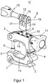
- the holder 1 in the FIGS. 1 to 3 has two clamp elements 2 and 3, which are connected via a flexible hinge 4.
- This flexible hinge 4 makes it possible to change the distance between the two clamp elements 2 and 3 and thus to adapt the holder 1 to different diameters of the object to which it is attached.
- the flexible hinge 4 has a connecting member 5.
- This link 5 is connected to the clamp members so that it is interchangeable.
- an adjusting spindle 6 is provided, which connects the upper clamp element 2 with the lower clamp element 3.
- the adjusting spindle is fixed in position by means of a locking lever 7.
- a camera holder 8 is arranged in the upper clamp member 2. This engages with a ball head 9 in a ball seat 10 a.
- the ball head 9 can be fixed by a fixing 11 of the camera holder 8.
- this fixation 11 a rotating device.
- the camera itself (not shown) is attached by means of a camera holder 12 on the camera holder 8.
- a rotating device 13 can be moved out of the camera holder.
- a camera (not shown) with suitable device (not shown) can be inserted into it and then closed.
- the camera recording has two slots such as the slot 16. This is limited by two walls 17 and 18. These are connected by the rotating device 13 and pulled against each other.
- the wall 18 at the level of the lower end of the slot has a notch 19.
- Replaceable damping elements 14, 15 provide sufficient damping between the holder 1 and an object (not shown) to which it is attached.
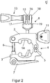
- both clamp members 22 and 23 are again connected on one side via a fixing spindle 24 which is fixable by a locking lever 25.
- a flexible hinge 26 On the opposite side there is a flexible hinge 26.
- This is arranged between two holding and fixing plates 27 and 28, from which the fastening plate 27 can be removed by means of the fastening screws 29 and 30. So the link can be replaced.
- This holder 21 has a camera holder 31. This engages with a ball head 32 in a ball socket 33 a. An attachment of the ball head 32 in the ball socket 33 takes place here by a clamping lever 34. Again, the camera can be used in the camera holder 35 by the fixation 36 is moved out of the camera recording.
- the ball socket 33 has pivoting recesses such as the pivoting recesses 37, 38, so that the camera holder 31 can be pivoted up to 90 °.
- the bracket 41 in FIG. 7 has two clamp members 42 and 43 which can be connected via a flexible hinge.
- This flexible hinge consists of the connecting member 45, which is held by two fastening screw elements 46, 47 in the clamp members 42, 43. By unscrewing these fastening screw elements 46, 47, the connecting member 45 can be pushed out of the clamp elements 42,43 and replaced by another link (not shown).
- the adjustment spindle provided on the side opposite the flexible hinge is composed of a spindle thread 48 and a spindle screw 49, which are connected via hinge components 50 and 51 to a locking lever 52.
- a plastic member 53 is arranged, which ensures that the shutter lever 52 can be easily closed by reducing the friction against the clamp member 43, in which the adjusting spindle engages in a fork.
- This plastic element 53 is connected by a screw 46 with the clamp member 43.
- the screw element 49 engages in closure elements 54, 55.
- damping elements 57, 58 are arranged. These are designed to be interchangeable and can be used by their shape in the clamp elements 42, 43 and hold in these form and locks.
- a camera holding member 59 is connected by a thread of a ball head bar 60.
- This ball head bar with the thread on the one hand and a ball head on the other hand is enclosed by two ball receiving elements 61, 62, which are held by a cover plate 63 in a recess in the upper clamp member 42.
- the cover plate 63 is fastened to the clamp member 42 by the screws 64, 65, 66 and 67.
- a fixing device is a rotating device with a knob 68 and a sunk in this screw 69 which is secured by a screw member 70 in the knob.
- a camera is inserted into a camera holder 59 by turning out the rotary device 71 accordingly. This is done via the screw member 72 on which the shim plate 73 is disposed between the rotating device 71 and the camera holder 59. This is held in the rotating device 71 by the screw member 74.
Description
Die Erfindung betrifft eine Halterung, die einen Halter zum Befestigen eines elektronischen Gerätes, insbesondere einer Kamera aufweist, wobei der Halter eine Geräteaufnahme aufweist, die einen Schlitz zwischen zwei Wänden aufweist, die jeweils eine Bohrung aufweisen, in der eine Drehvorrichtung geführt ist, die die Wände des Schlitzes miteinander verbindet.The invention relates to a holder having a holder for fixing an electronic device, in particular a camera, wherein the holder has a device receptacle having a slot between two walls, each having a bore in which a rotating device is guided, which Walls of the slot connects to each other.
Halterungen zum Befestigen von elektrischen Geräten, insbesondere von Kameras wie beispielsweise Action-Kameras sind aus dem Stand der Technik zahlreich bekannt. Diese erlauben beispielsweise mit unterschiedlich langen verstellbaren Silikonbändern die Befestigung einer Plastik-Halterung an einem Helm, einem Fahrradlenker, einem Außenspiegel oder einem Segelmast.Mounts for attaching electrical equipment, especially cameras such as action cameras are well known in the art. These allow, for example, with different lengths adjustable silicone straps attachment of a plastic bracket to a helmet, a bicycle handlebar, an outside mirror or a sail mast.
Eine gattungsgemäße Halterung ist aus der
Aufgabe der vorliegenden Erfindung ist es, solche aus dem Stand der Technik bekannten Vorrichtungen zu verbessern.The object of the present invention is to improve such devices known from the prior art.
Diese Aufgabe wird nach einem ersten Aspekt der Erfindung durch eine Halterung zum Befestigen eines elektrischen Geräts, insbesondere einer Kameramit den Merkmalen des Patentanspruchs 1 gelöst.This object is achieved according to a first aspect of the invention by a holder for fastening an electrical device, in particular a camera with the features of claim 1.
Eine derartige Halterung ist aus der
Ähnliche Probleme entstehen beim Anbringen einer Halterung, wie sie aus der
Auch andere Gegenstände können mit der Halterung befestigt werden wie beispielsweise ein Lampe oder eine Messeinrichtung. Auch eine Befestigung einer mechanischen Vorrichtung ist möglich. Unter einer Stange ist dabei eine stangenförmige Vorrichtung zu verstehen, wie beispielsweise eben eine Verstrebung eines Helms, ein Fahrradlenker, ein Sattelrohr, ein Stativbestandteil oder ein Segelmast. Unter einer Flexscharnierung ist eine Scharnierung zu verstehen, die unterschiedliche Abstände zwischen den beiden Schellenelementen überbrücken kann. So ist es möglich, die Halterung an Stangen unterschiedlichen Durchmessers anzubringen. So liegt der Durchmesser eines Sattelrohrs beispielsweise in der Größenordnung von 25mm, der eines Segelmastes mit einer Größenordnung von 60mm oder mehr. An diese kann die Halterung mittels der Flexscharnierung angepasst werden. So wird eine hohe Variabilität der Halterung gewährleistet.Other items can be attached to the bracket, such as a lamp or meter. An attachment of a mechanical device is possible. Under a rod while a rod-shaped device is to be understood, such as just a brace of a helmet, a bicycle handlebar, a seat tube, a tripod component or a sailing mast. A flexible hinge is a hinge that can bridge different distances between the two clamp elements. So it is possible to attach the bracket to rods of different diameters. For example, the diameter of a seat tube is on the order of 25mm, that of a sail mast on the order of 60mm or more. At this the holder can be adjusted by means of the flexible hinge. This ensures a high variability of the holder.
Von Vorteil ist, wenn die Flexscharnierung ein Verbindungsglied aufweist und dieses mit den Schellenelementen so verbunden ist, dass es austauschbar ist. Ein solches austauschbares Verbindungsglied ist eine Möglichkeit, eine Flexscharnierung auszubilden. Werden in einem Set mit einer Halterung mehrere Verbindungsglieder mitgeliefert, so kann der Scharnierabstand durch Austausch des Verbindungsgliedes verändert werden. Insbesondere kann ein Teil eines Schellenelementkörpers entfernt werden, sodass die Lagerung des Verbindungsglieds im Schellenelement freigelegt wird. Das Verbindungsglied kann dann ausgetauscht werden und der Schellenelementkörper wieder verschlossen werden. Dies kann beispielsweise durch eine Befestigung mit einer Schraube erfolgen.It is advantageous if the flexible hinge has a connecting member and this is connected to the clamp elements so that it is interchangeable. Such an exchangeable link is one way to form a flex hinge. If several connecting links are supplied in a set with a bracket, the hinge distance can be changed by replacing the connecting link. In particular, a part of a clamp member body can be removed, so that the bearing of the link is exposed in the clamp member. The connecting member can then be exchanged and the clamp element body can be closed again. This can be done for example by attachment with a screw.
Auf einer der Scharnierung gegenüberliegenden Seite, an einem ersten Schellenelement, kann die Halterung eine Spindelstange mit einem Verschlusshebel und an einem zweiten Schellenelement eine Gabel aufweisen, wobei die Spindelstange mit dem Verschlusshebel im geschlossenen Zustand der Halterung formschlüssig in die Gabel eingreift.On a side opposite the hinge side, on a first clamp member, the holder may comprise a spindle rod with a locking lever and a second clamp member a fork, wherein the spindle rod engages with the locking lever in the closed state of the holder form-fitting manner in the fork.
Durch die Spindelstange ist auch auf der der Scharnierung gegenüber liegenden Seite eine Längenverstellbarkeit gewährleistet. So ist sichergestellt, dass auch hier eine Anpassung der Halterung an unterschiedliche Durchmesser einer stangenförmigen Vorrichtung möglich ist. Auch andere Verschlussmechanismen auf der der Scharnierung gegenüberliegenden Seite, die eine Längenverstellbarkeit gewährleisten, sind denkbar, so eine Zahnstange, ein Seil oder eine Gewindestange.Through the spindle rod length adjustment is also guaranteed on the side opposite the hinge. This ensures that an adaptation of the holder to different diameters of a rod-shaped device is also possible here. Other locking mechanisms on the opposite side of the hinge, which ensure a length adjustability, are conceivable, such as a rack, a rope or a threaded rod.
Zur Erleichterung des Verschließens kann zwischen dem Schellenelement und dem Verschlusshebel ein Plastikelement angeordnet sein, um die Reibung der beiden Oberflächen aus identischem Material zu reduzieren.To facilitate the closing, a plastic element can be arranged between the clamp element and the closure lever in order to reduce the friction of the two surfaces of identical material.
Vorteilhafterweise ist auf der Innenseite eines Schellenelements ein Dämpfelement angeordnet. So kann eine Dämpfung gegenüber Erschütterungen der Stange erfolgen.Advantageously, a damping element is arranged on the inside of a clamp element. Thus, a damping against shocks of the rod can be done.
Vorteilhafterweise ist das Dämpfelement austauschbar befestigt. So ist es möglich, das Dämpfelement an Belastungssituationen anzupassen.Advantageously, the damping element is mounted exchangeably. It is thus possible to adapt the damping element to load situations.
Die Halterung kann einen Halter für ein elektronisches Gerät aufweisen. Hierbei kann es sich insbesondere um einen Kamerahalter handeln. Dies kann an einem der Schellenelemente befestigt sein. Unter einem Halter für ein elektrisches Gerät ist dabei jede Vorrichtung zu verstehen, die dazu geeignet ist ein solches Gerät an der Halterung zu befestigen.The holder may include a holder for an electronic device. This may in particular be a camera holder. This can be attached to one of the clamp elements. Under a holder for an electrical device is understood to mean any device that is suitable to attach such a device to the holder.
Zudem kann die Halterung auch Halter für andere Vorrichtungen aufweisen. Auch eine Aufnahmebohrung in der ein Gerät beziehungsweise weitere Gegenstände befestigt werden können ist vorteilhaft.In addition, the holder may also have holders for other devices. A receiving bore in which a device or other objects can be attached is advantageous.
Insbesondere kann das Schellenelement eine Kugelpfanne aufweisen, in die der Halter für ein elektronisches Gerät mit einem Kugelkopf eingreift.In particular, the clamp member may comprise a ball socket into which engages the holder for an electronic device with a ball head.
Vorteilhafterweise wirkt eine Fixierungselement auf den Kugelkopf in der Kugelpfanne ein. Unter einem Fixierungselement ist dabei jede Vorrichtung zu verstehen, die den Kugelkopf in einer bestimmten Position fixiert. Hierbei kann es sich beispielsweise um eine Schraube, einen Spannhebel oder eine Drehvorrichtung handeln, die auf den Kugelkopf in der Kugelpfanne einwirken.Advantageously, a fixing element acts on the ball head in the ball socket. Under a fixing element is each device to understand that fixes the ball head in a certain position. This may be, for example, a screw, a clamping lever or a rotating device, which act on the ball head in the ball socket.
Vorteilhafterweise sind in der Kugelpfanne Schwenkaussparungen vorgesehen. So kann in bestimmten Richtungen die Halterung in extreme Winkel verschwenkt werden. Die Schwenkaussparungen können beispielsweise im 90° Winkel angeordnet sein. Hierdurch werden die wesentlichen Raumrichtungen gut abgedeckt.Advantageously, pivot recesses are provided in the ball socket. Thus, in certain directions, the bracket can be pivoted to extreme angles. The pivoting recesses can be arranged, for example, at 90 ° angle. As a result, the essential spatial directions are well covered.
Ein Aspekt der Erfindung ist, dass der Halter eine Geräteaufnahme aufweist, wobei die Geräteaufnahme einen Schlitz aufweist und eine Wand des Schlitzes an einer dem Schlitz abgewandten Seite der Wand eine Kerbe aufweist. In eine solche Geräteaufnahme kann eine am elektrischen Gerät angebrachte Befestigungsvorrichtung eingeführt werden und in dem Schlitz befestigt werden. Von Vorteil ist, wenn die Geräteaufnahme mehrere Schlitze aufweist. Diese können entsprechend mit mehreren plattenförmigen Elementen an einer Gerätebefestigungsvorrichtung wechselwirken. Mehrere Schlitze erhöhen dabei die Stabilität der Interaktion. Die Befestigungsvorrichtung an dem Gerät kann dabei plattenförmig so ausgestaltet sein, dass eine Platte form- und/oder kraftschlüssig in den Schlitz eingreift. Sowohl die Wände des Schlitzes als auch die Befestigungsvorrichtung an der Kamera können beispielsweise eine Bohrung aufweisen. Durch diese kann eine Drehvorrichtung geführt werden, diese verbindet die Wände des Schlitzes miteinander und kann so ausgestaltet sein, dass sie diese gegen die Befestigungseinrichtung des elektronischen Gerätes zieht. Die an der Außenseite einer Wand vorgesehene Kerbe hat dabei den Vorteil, dass diese Wand leichter verformbar ist und daher besser an der Befestigungsvorrichtung des elektrischen Geräts anliegen wird. Auch mehrere Kerben sowohl an allen Wänden insbesondere den äußeren Wänden der Geräteaufnahme als auch mehrere Schlitze an einer Wand des Schlitzes können dabei vorteilhaft sein. Von Vorteil ist, wenn die Kerbe am unteren Ende der Wand auf der Höhe des unteren Endes des Schlitzes angeordnet ist.One aspect of the invention is that the holder has a device receptacle, wherein the device receptacle has a slot and a wall of the slot has a notch on a side of the wall facing away from the slot. In such a device receptacle attached to the electrical device fastening device can be inserted and secured in the slot. It is advantageous if the device receptacle has a plurality of slots. These can accordingly interact with a plurality of plate-shaped elements on a device fastening device. Multiple slots increase the stability of the interaction. The fastening device on the device can be designed plate-shaped so that a plate positively and / or non-positively engages in the slot. For example, both the walls of the slot and the fastening device on the camera may have a bore. Through this, a rotating device can be performed, this connects the walls of the slot with each other and so can be configured that it pulls against the fastening device of the electronic device. The notch provided on the outside of a wall has the advantage that this wall is easier to deform and therefore better abuts the fastening device of the electrical device. Also, several notches both on all walls in particular the outer walls of the device receptacle as well as a plurality of slots on a wall of the slot may be advantageous. It is advantageous if the notch is arranged at the lower end of the wall at the level of the lower end of the slot.
Einzelne Elemente oder alle Elemente der Halterung können aus Aluminium sein. Dieses hochwertige Material zeigt wenig Verschleiß und ist im Vergleich zu dem Stand der Technik, wie beispielsweise Plastik, sehr stabil. Dies ist insbesondere im Extremsportbereich von Vorteil.Individual elements or all elements of the support may be made of aluminum. This high quality material shows little wear and is very stable compared to the prior art, such as plastic. This is particularly advantageous in extreme sports.
Ein weiterer Aspekt der Erfindung betrifft ein Set mit einer Halterung, wobei es eine Halterung und Verbindungsglieder unterschiedlicher Länge aufweist. So können beispielsweise ein kürzeres, ein mittleres und ein langes Verbindungsglied vorgesehen sein, um unterschiedliche Stangendurchmesser zu erfassen.Another aspect of the invention relates to a set with a holder, wherein it has a holder and connecting members of different lengths. For example, a shorter, a middle and a long link may be provided to detect different rod diameters.
Ein letzter Aspekt der Erfindung betrifft ein Set mit einer Halterung und Dämpfelementen mit unterschiedlichen Dämpfungsgraden. Durch unterschiedliche Dämpfungsgrade ist es möglich, das Set an unterschiedliche Einsatzbedingungen anzupassen. So schwankt die Erschütterungsqualität, die beispielsweise beim Mountainbiken anfällt, stark und unterscheidet sich wesentlich von einer beispielsweise beim Segeln anfallenden Belastung.A final aspect of the invention relates to a set with a holder and damping elements with different degrees of damping. Due to different degrees of damping, it is possible to adapt the set to different operating conditions. So the vibration quality varies, which arises, for example, when mountain biking, strong and differs significantly from, for example, when sailing load incurred.
Vorteilhafterweise sind die Dämpfelemente verschiedenfarblich markiert, um eine leichtere Erkennbarkeit der unterschiedlichen Dämpfungsgrade zu gewährleisten. Insbesondere können die Dämpfelemente durchgängig aus unterschiedlich farbigen Kunststoffen gefertigt sein.Advantageously, the damping elements are marked in different colors to ensure easier recognition of the different degrees of damping. In particular, the damping elements can be made entirely of different colored plastics.
Die Erfindung wird nachfolgend anhand von Ausführungsbeispielen unter Bezugnahme auf die Zeichnung näher erläutert.The invention will be explained in more detail by means of embodiments with reference to the drawing.
Hierin zeigen:
- Figur 1
- eine dreidimensionale Darstellung einer Halterung mit einem Halter für ein elektronisches Gerät, wobei dieser durch eine Drehvorrichtung fixiert wird,
Figur 2- eine Seitenansicht einer Halterung mit einem Halter für ein elektronisches Gerät, wobei dieser durch eine Drehvorrichtung fixiert wird,
Figur 3- einen Schnitt durch eine Halterung mit einem Halter für ein elektronisches Gerät, wobei dieser durch eine Drehvorrichtung fixiert wird,
Figur 4- eine dreidimensionale Darstellung einer Halterung mit einem Halter für ein elektronisches Gerät, wobei dieser mit einem Spannhebel fixiert wird,
Figur 5- eine Seitenansicht einer Halterung mit einem Halter für ein elektronisches Gerät, wobei dieser mit einem Spannhebel fixiert wird,
Figur 6- einen Querschnitt durch eine Halterung mit einem Halter für ein elektronisches Gerät, wobei dieser mit einem Spannhebel fixiert wird und
Figur 7- eine Explosionszeichnung einer Halterung mit einem Halter für ein elektronisches Gerät, wobei dieser durch eine Drehvorrichtung fixiert wird.
- FIG. 1
- a three-dimensional representation of a holder with a holder for an electronic device, which is fixed by a rotating device,
- FIG. 2
- a side view of a holder with a holder for an electronic device, which is fixed by a rotating device,
- FIG. 3
- a section through a holder with a holder for an electronic device, which is fixed by a rotating device,
- FIG. 4
- a three-dimensional representation of a holder with a holder for an electronic device, wherein this is fixed with a clamping lever,
- FIG. 5
- a side view of a holder with a holder for an electronic device, wherein this is fixed with a clamping lever,
- FIG. 6
- a cross section through a holder with a holder for an electronic device, which is fixed with a clamping lever and
- FIG. 7
- an exploded view of a holder with a holder for an electronic device, which is fixed by a rotating device.
Die Halterung 1 in den
Bei einer Halterung 21 wie in den
Die Halterung 41 in
Claims (15)
- Mount (1), which has a holder (8) for attaching an electronic device, and in particular a camera, wherein the holder (8) has a device receptacle (12), which has a slot (16) between two walls, characterized in that the two walls each have a through hole in which a rotation device is guided, which connects the walls of the slot to one another, wherein a wall (18) of the slot (16) has a notch (19) on a side of the wall (18) facing away from the slot (16).
- Mount according to Claim 1, characterized in that the device receptacle (12) has a plurality of slots (16).
- Mount according to Claim 2, characterized in that the slots (16) interact with a plurality of plate-shaped elements of the device receptacle.
- Mount according to Claim 2 or 3, characterized in that notches (19) are provided on the outer walls (18) of the device receptacle (12).
- Mount according to of any one of the previous claims, characterized in that the notch (19) is arranged at the lower end of the wall (18) at the height of the lower end of the slot (16).
- Mount according to of any one of the previous claims, characterized in that the notch (19) extends perpendicular to the slot (16).
- Mount according to of any one of the previous claims, characterized in that said mount has a pipe clamp with two clamp elements (2, 3), which are connected to a flexible hinge (4) that has a connecting link (5), wherein on the side opposite the flexible hinge (4) an adjustment spindle (6) is provided, which connects the clamp elements (2, 3) to one another.
- Mount according to Claim 7, characterized in that the connecting link (5) is connected to the clamp elements (2, 3) in such a way that it can be replaced.
- Mount according to Claim 7 or 8, characterized in that on a side located opposite the hinge (4), on a first clamp element (42) the mount (1) has a spindle rod (49) with a locking lever (52) and on a second clamp element (43) has a fork, wherein in the closed condition of the mount, the spindle rod (49) engages in the fork with a form fit.
- Mount according to of any one of the previous claims, characterized in that one clamp element (2, 3) of the mount has a ball socket (10), in which the holder engages with a ball head (9), wherein a fixing element (11) acts upon the ball head (9) in the ball socket (10).
- Mount according to Claim 10, characterized in that pivot recesses (37, 38) are provided in the ball socket (10), which are arranged at an angle of 90°.
- Mount according to of any one of the previous claims, characterized in that individual elements or all elements of the mount are formed of aluminium.
- Set having a mount according to any one of Claims 7-12, characterized in that said set has a mount and connecting links (5) of different length.
- Set according to Claim 13, characterized in that said set has a mount and damping elements (14, 15) of different degrees of damping.
- Set according to Claim 14, characterized in that the damping elements (14, 15) are marked in different colours.
Applications Claiming Priority (4)
| Application Number | Priority Date | Filing Date | Title |
|---|---|---|---|
| DE102012021009 | 2012-10-26 | ||
| DE201310005766 DE102013005766A1 (en) | 2012-10-26 | 2013-04-05 | Support structure of support assembly for e.g. camera, has flexible hinge system including connecting link which is interchangeably connected with upper and lower bracket elements, and camera holder arranged in upper bracket element |
| US201361809517P | 2013-04-08 | 2013-04-08 | |
| PCT/DE2013/000632 WO2014063678A2 (en) | 2012-10-26 | 2013-10-28 | Mount, and set comprising a mount |
Publications (2)
| Publication Number | Publication Date |
|---|---|
| EP2912362A2 EP2912362A2 (en) | 2015-09-02 |
| EP2912362B1 true EP2912362B1 (en) | 2017-12-27 |
Family
ID=50555900
Family Applications (1)
| Application Number | Title | Priority Date | Filing Date |
|---|---|---|---|
| EP13824478.5A Active EP2912362B1 (en) | 2012-10-26 | 2013-10-28 | Mount, and set comprising a mount |
Country Status (4)
| Country | Link |
|---|---|
| US (1) | US20150286115A1 (en) |
| EP (1) | EP2912362B1 (en) |
| DE (2) | DE102013005766A1 (en) |
| WO (1) | WO2014063678A2 (en) |
Families Citing this family (30)
| Publication number | Priority date | Publication date | Assignee | Title |
|---|---|---|---|---|
| US9651070B2 (en) * | 2013-10-03 | 2017-05-16 | Shimano Inc. | Bicycle clamp structure and bicycle operating device |
| CN110578738B (en) * | 2014-01-15 | 2021-05-18 | 蒂埃尔威有限公司 | Sensor fixing device |
| CN104896276B (en) * | 2014-03-06 | 2017-02-22 | 信泰光学(深圳)有限公司 | Image capturing device and clamping mechanism |
| US9681029B2 (en) * | 2014-10-02 | 2017-06-13 | Gopro, Inc. | Swivel camera mount |
| CN104806851A (en) * | 2015-04-08 | 2015-07-29 | 昆山德商达金软件技术有限公司 | Movable camera mounting seat |
| US9829017B2 (en) * | 2015-10-16 | 2017-11-28 | Martek Limited | Mounting device for temporarily affixing an auxiliary device to a motor control center |
| US9778548B2 (en) * | 2015-10-20 | 2017-10-03 | Kenneth John Achenbach | Quick connect camera mounting system |
| GB2546075A (en) * | 2016-01-05 | 2017-07-12 | Oclu Ltd | A camera mount |
| USD798940S1 (en) * | 2016-01-22 | 2017-10-03 | Gopro, Inc. | Camera pole mount |
| USD798939S1 (en) * | 2016-01-22 | 2017-10-03 | Gopro, Inc. | Camera pole mount |
| US10493824B2 (en) * | 2016-10-20 | 2019-12-03 | Sportech, Inc. | Clamp for vehicle accessory |
| US10288987B2 (en) * | 2016-12-09 | 2019-05-14 | Moises H Olmos-Calderon | Tripod accessory clamp |
| USD841075S1 (en) * | 2017-07-17 | 2019-02-19 | Oclu Limited | Bike mount for a portable video camera |
| CN110481681B (en) * | 2018-05-14 | 2021-04-20 | A·肖赫 | Handlebar clamping device |
| DE202019107267U1 (en) | 2018-08-07 | 2020-02-27 | Gopro, Inc. | Camera and camera holder |
| USD894256S1 (en) | 2018-08-31 | 2020-08-25 | Gopro, Inc. | Camera mount |
| USD905786S1 (en) | 2018-08-31 | 2020-12-22 | Gopro, Inc. | Camera mount |
| USD892910S1 (en) * | 2019-01-10 | 2020-08-11 | Zhongshan Forever Photographic Equipment Co. Ltd | Camera mount |
| US10765185B1 (en) * | 2019-03-28 | 2020-09-08 | Tim Wengerd | Umbrella holder |
| USD921095S1 (en) | 2019-06-19 | 2021-06-01 | Gopro, Inc. | Camera mount |
| US11940093B2 (en) | 2019-08-28 | 2024-03-26 | Techna Display Limited | Brackets |
| USD920419S1 (en) | 2019-09-17 | 2021-05-25 | Gopro, Inc. | Camera |
| USD1023118S1 (en) | 2019-09-13 | 2024-04-16 | Gopro, Inc. | Screw of a camera mount |
| US11755070B2 (en) * | 2019-12-09 | 2023-09-12 | Ingenio Aerospace Inc. | Computing device holder and method of storing thereof |
| USD966242S1 (en) | 2020-03-11 | 2022-10-11 | Hubbell Incorporated (Delaware) | Pole mount |
| USD946074S1 (en) | 2020-08-14 | 2022-03-15 | Gopro, Inc. | Camera |
| DE102020212618A1 (en) * | 2020-10-06 | 2022-04-07 | Magna Steyr Fahrzeugtechnik Ag & Co Kg | precision coupling |
| GB2605644B (en) * | 2021-04-09 | 2023-04-05 | Nonstop Int Ltd | Action camera mounting device |
| CN114877175B (en) * | 2022-03-29 | 2023-07-14 | 华能国际电力股份有限公司上海石洞口第二电厂 | Ship unloader is based on image recognition equipment installation device |
| USD986947S1 (en) * | 2023-01-06 | 2023-05-23 | Shenzhen Neewer Technology Co. Ltd | Camera clamp |
Family Cites Families (26)
| Publication number | Priority date | Publication date | Assignee | Title |
|---|---|---|---|---|
| US1303347A (en) * | 1919-05-13 | Pipe-hanger | ||
| DE583422C (en) * | 1933-09-02 | Johannes Robert Schmutzler | Clamp tripod | |
| US2589520A (en) * | 1947-05-27 | 1952-03-18 | Wallenius Tuomo Jaakk Hermanni | Fixture for cameras or other similar apparatus |
| DE2640438A1 (en) * | 1976-09-08 | 1978-03-09 | Zippel Gmbh & Co Kg Herbert | DEVICE FOR COMBINING LEAF-LIKE COLLECTIVE MATERIAL |
| US4445657A (en) * | 1981-10-13 | 1984-05-01 | Breckenridge Gerald H | Spray boom mounting assembly |
| US4506418A (en) * | 1982-12-20 | 1985-03-26 | Parker-Hannifin Corporation | Muffler clamp |
| US4702447A (en) * | 1984-11-29 | 1987-10-27 | Westwood Iii Samuel M | Clamp device |
| US4953820A (en) * | 1985-06-20 | 1990-09-04 | Universal Consolidated Methods, Inc. | Lamp with retaining ring |
| US4901963A (en) * | 1985-06-20 | 1990-02-20 | Universal Consolidated Methods, Inc. | Adjustable clamp |
| IT1208418B (en) * | 1987-04-29 | 1989-06-12 | Campagnolo Spa | DEVICE FOR THE LOCKING OF AN ORGAN ON A FRAME OF A BIKE OR SIMILAR |
| GB2213369A (en) * | 1987-12-09 | 1989-08-16 | Okabe Kinzoku Kogyo Gomei Kais | Variable angle supporting device |
| GB8816600D0 (en) * | 1988-07-13 | 1988-08-17 | Proctor A R | Camera claw(camera clamp) |
| US5540475A (en) * | 1994-07-05 | 1996-07-30 | Custom Form Manufacturing, Inc. | Tonneau cover assembly clamping assembly |
| US5647565A (en) * | 1996-03-07 | 1997-07-15 | Wei; David | Tripod |
| US6439526B1 (en) * | 1999-04-20 | 2002-08-27 | Clemco Products, Inc. | Jointed clamp for garment bag |
| US6681971B2 (en) * | 2001-03-08 | 2004-01-27 | Thule Sweden Ab | Variably configurable securement arrangement in a load carrier |
| US6793186B2 (en) * | 2001-05-25 | 2004-09-21 | Jac Products Inc. | Clamp for a cross bar |
| US6568644B2 (en) * | 2001-05-25 | 2003-05-27 | Jac Products Inc. | Clamp for a cross bar |
| WO2005033524A1 (en) * | 2003-10-03 | 2005-04-14 | Micronix Pty Ltd | Universal equipment clamp |
| US7152834B2 (en) * | 2004-01-12 | 2006-12-26 | Feng Ling Hsu | Adjustable attachment device for attaching an object to a tubular member |
| DE202004001608U1 (en) * | 2004-02-03 | 2004-05-06 | Wu, Shi-Ming, Dali | Pan and tilt head mounting for camera incorporates a universal joint supported on a clamp which fits onto a support bar |
| DE202005001986U1 (en) * | 2005-02-07 | 2005-04-14 | Richter, Harald | Universal joint arrangement between a device holder and a support arm or a console |
| GB0519716D0 (en) * | 2005-09-28 | 2005-11-02 | Rigidal Systems Ltd | Clamp assembly for a standing seam |
| US7861982B1 (en) * | 2006-11-16 | 2011-01-04 | International Clamps, Inc. | Subsea clamp for hoses and control lines |
| US8408507B2 (en) * | 2010-10-06 | 2013-04-02 | Chi-Perng Liu | Locking device |
| US8469325B2 (en) * | 2011-10-26 | 2013-06-25 | Tsung-Yao Yu | Musical instrument stand with an angle adjustment function |
-
2013
- 2013-04-05 DE DE201310005766 patent/DE102013005766A1/en not_active Withdrawn
- 2013-10-28 DE DE112013005153.2T patent/DE112013005153A5/en not_active Ceased
- 2013-10-28 EP EP13824478.5A patent/EP2912362B1/en active Active
- 2013-10-28 WO PCT/DE2013/000632 patent/WO2014063678A2/en active Application Filing
- 2013-10-28 US US14/437,332 patent/US20150286115A1/en not_active Abandoned
Also Published As
| Publication number | Publication date |
|---|---|
| WO2014063678A2 (en) | 2014-05-01 |
| WO2014063678A3 (en) | 2014-07-17 |
| EP2912362A2 (en) | 2015-09-02 |
| DE112013005153A5 (en) | 2015-07-09 |
| DE102013005766A1 (en) | 2014-05-15 |
| US20150286115A1 (en) | 2015-10-08 |
Similar Documents
| Publication | Publication Date | Title |
|---|---|---|
| EP2912362B1 (en) | Mount, and set comprising a mount | |
| DE10125400B4 (en) | hanger | |
| EP3003198B1 (en) | Adapter device for an operating table | |
| AT502475B1 (en) | Carrier fastening device for rails, has rail claw with claw jaws, where one of claw jaws and/or claw part is secured in preset position in form fit manner by grooves or in cross section of sides of claw part and carrier or retaining unit | |
| DE102010004739A1 (en) | Device for clamping workpieces on a base | |
| DE102006018237A1 (en) | Device for fixing container, especially basket, to two-wheeler's luggage rack has clamping arrangement for fixing at least one claw on basket to longitudinal bar on rack that varies separation of claws when operated | |
| EP1219215B1 (en) | Suspension system for picture frame | |
| EP1541917A2 (en) | Balancing device for hand-held cameras | |
| DE10145197B4 (en) | Decoupled weight compensation for a camera balance device | |
| EP3009738B1 (en) | Clamp mounting | |
| DE102013003822B3 (en) | Fitting tray for e.g. shampoo container, has holding frame comprising work area for enclosing water supply, where one end of work area is swingably supported at holding frame and another end of work area is lockable at holding frame | |
| DE102011053660A1 (en) | Fastening device for image reproduction apparatus e.g. projector at wall in room, has mounting rail movably and displaceably arranged in suspension device, where retaining rail is movably and displaceably retained in mounting rail | |
| DE202016001215U1 (en) | connecting element | |
| DE202004006726U1 (en) | Surgical head frame has a support bracket with a single point mounting on a threaded fitting at one end and with selective two point and three point mountings on the other end | |
| EP1939519B1 (en) | Tripod | |
| DE112006003346T5 (en) | Clamping device, in particular for attachment to elements of variable cross-section | |
| EP2195103B1 (en) | Snow-ski board with binding | |
| DE10145199B4 (en) | Cardanic suspension device for a camera balance device | |
| EP1727727A1 (en) | Device for fixing an adapter to adjacent bar parts of bicycles | |
| DE102010037727B4 (en) | Clamping device, in particular for a bicycle | |
| EP0508157A2 (en) | Light projector | |
| DE102009002058B4 (en) | Measuring system with a fitting holder with multi-function clamping ring | |
| DE3238707A1 (en) | CAMERA MOUNTING DEVICE | |
| EP0019243A1 (en) | Stand for projection screens | |
| DE10351865A1 (en) | Mounting for the detachable fitting of a container to the handlebar of a bicycle has a quick-release fastening section to which a support section is fitted so that it cannot rotate while an adapter unit is mounted on the support |
Legal Events
| Date | Code | Title | Description |
|---|---|---|---|
| PUAI | Public reference made under article 153(3) epc to a published international application that has entered the european phase |
Free format text: ORIGINAL CODE: 0009012 |
|
| 17P | Request for examination filed |
Effective date: 20150521 |
|
| AK | Designated contracting states |
Kind code of ref document: A2 Designated state(s): AL AT BE BG CH CY CZ DE DK EE ES FI FR GB GR HR HU IE IS IT LI LT LU LV MC MK MT NL NO PL PT RO RS SE SI SK SM TR |
|
| AX | Request for extension of the european patent |
Extension state: BA ME |
|
| DAX | Request for extension of the european patent (deleted) | ||
| STAA | Information on the status of an ep patent application or granted ep patent |
Free format text: STATUS: EXAMINATION IS IN PROGRESS |
|
| 17Q | First examination report despatched |
Effective date: 20170118 |
|
| GRAP | Despatch of communication of intention to grant a patent |
Free format text: ORIGINAL CODE: EPIDOSNIGR1 |
|
| STAA | Information on the status of an ep patent application or granted ep patent |
Free format text: STATUS: GRANT OF PATENT IS INTENDED |
|
| INTG | Intention to grant announced |
Effective date: 20170811 |
|
| GRAA | (expected) grant |
Free format text: ORIGINAL CODE: 0009210 |
|
| STAA | Information on the status of an ep patent application or granted ep patent |
Free format text: STATUS: THE PATENT HAS BEEN GRANTED |
|
| GRAS | Grant fee paid |
Free format text: ORIGINAL CODE: EPIDOSNIGR3 |
|
| AK | Designated contracting states |
Kind code of ref document: B1 Designated state(s): AL AT BE BG CH CY CZ DE DK EE ES FI FR GB GR HR HU IE IS IT LI LT LU LV MC MK MT NL NO PL PT RO RS SE SI SK SM TR |
|
| REG | Reference to a national code |
Ref country code: GB Ref legal event code: FG4D Free format text: NOT ENGLISH |
|
| REG | Reference to a national code |
Ref country code: CH Ref legal event code: EP |
|
| REG | Reference to a national code |
Ref country code: AT Ref legal event code: REF Ref document number: 958605 Country of ref document: AT Kind code of ref document: T Effective date: 20180115 |
|
| REG | Reference to a national code |
Ref country code: IE Ref legal event code: FG4D Free format text: LANGUAGE OF EP DOCUMENT: GERMAN |
|
| REG | Reference to a national code |
Ref country code: DE Ref legal event code: R096 Ref document number: 502013009143 Country of ref document: DE |
|
| PG25 | Lapsed in a contracting state [announced via postgrant information from national office to epo] |
Ref country code: NO Free format text: LAPSE BECAUSE OF FAILURE TO SUBMIT A TRANSLATION OF THE DESCRIPTION OR TO PAY THE FEE WITHIN THE PRESCRIBED TIME-LIMIT Effective date: 20180327 Ref country code: LT Free format text: LAPSE BECAUSE OF FAILURE TO SUBMIT A TRANSLATION OF THE DESCRIPTION OR TO PAY THE FEE WITHIN THE PRESCRIBED TIME-LIMIT Effective date: 20171227 Ref country code: FI Free format text: LAPSE BECAUSE OF FAILURE TO SUBMIT A TRANSLATION OF THE DESCRIPTION OR TO PAY THE FEE WITHIN THE PRESCRIBED TIME-LIMIT Effective date: 20171227 |
|
| REG | Reference to a national code |
Ref country code: NL Ref legal event code: MP Effective date: 20171227 |
|
| REG | Reference to a national code |
Ref country code: LT Ref legal event code: MG4D |
|
| PG25 | Lapsed in a contracting state [announced via postgrant information from national office to epo] |
Ref country code: GR Free format text: LAPSE BECAUSE OF FAILURE TO SUBMIT A TRANSLATION OF THE DESCRIPTION OR TO PAY THE FEE WITHIN THE PRESCRIBED TIME-LIMIT Effective date: 20180328 Ref country code: HR Free format text: LAPSE BECAUSE OF FAILURE TO SUBMIT A TRANSLATION OF THE DESCRIPTION OR TO PAY THE FEE WITHIN THE PRESCRIBED TIME-LIMIT Effective date: 20171227 Ref country code: RS Free format text: LAPSE BECAUSE OF FAILURE TO SUBMIT A TRANSLATION OF THE DESCRIPTION OR TO PAY THE FEE WITHIN THE PRESCRIBED TIME-LIMIT Effective date: 20171227 Ref country code: LV Free format text: LAPSE BECAUSE OF FAILURE TO SUBMIT A TRANSLATION OF THE DESCRIPTION OR TO PAY THE FEE WITHIN THE PRESCRIBED TIME-LIMIT Effective date: 20171227 Ref country code: BG Free format text: LAPSE BECAUSE OF FAILURE TO SUBMIT A TRANSLATION OF THE DESCRIPTION OR TO PAY THE FEE WITHIN THE PRESCRIBED TIME-LIMIT Effective date: 20180327 |
|
| PG25 | Lapsed in a contracting state [announced via postgrant information from national office to epo] |
Ref country code: NL Free format text: LAPSE BECAUSE OF FAILURE TO SUBMIT A TRANSLATION OF THE DESCRIPTION OR TO PAY THE FEE WITHIN THE PRESCRIBED TIME-LIMIT Effective date: 20171227 |
|
| PG25 | Lapsed in a contracting state [announced via postgrant information from national office to epo] |
Ref country code: ES Free format text: LAPSE BECAUSE OF FAILURE TO SUBMIT A TRANSLATION OF THE DESCRIPTION OR TO PAY THE FEE WITHIN THE PRESCRIBED TIME-LIMIT Effective date: 20171227 Ref country code: EE Free format text: LAPSE BECAUSE OF FAILURE TO SUBMIT A TRANSLATION OF THE DESCRIPTION OR TO PAY THE FEE WITHIN THE PRESCRIBED TIME-LIMIT Effective date: 20171227 Ref country code: CY Free format text: LAPSE BECAUSE OF FAILURE TO SUBMIT A TRANSLATION OF THE DESCRIPTION OR TO PAY THE FEE WITHIN THE PRESCRIBED TIME-LIMIT Effective date: 20171227 Ref country code: CZ Free format text: LAPSE BECAUSE OF FAILURE TO SUBMIT A TRANSLATION OF THE DESCRIPTION OR TO PAY THE FEE WITHIN THE PRESCRIBED TIME-LIMIT Effective date: 20171227 Ref country code: SK Free format text: LAPSE BECAUSE OF FAILURE TO SUBMIT A TRANSLATION OF THE DESCRIPTION OR TO PAY THE FEE WITHIN THE PRESCRIBED TIME-LIMIT Effective date: 20171227 |
|
| PG25 | Lapsed in a contracting state [announced via postgrant information from national office to epo] |
Ref country code: SM Free format text: LAPSE BECAUSE OF FAILURE TO SUBMIT A TRANSLATION OF THE DESCRIPTION OR TO PAY THE FEE WITHIN THE PRESCRIBED TIME-LIMIT Effective date: 20171227 Ref country code: RO Free format text: LAPSE BECAUSE OF FAILURE TO SUBMIT A TRANSLATION OF THE DESCRIPTION OR TO PAY THE FEE WITHIN THE PRESCRIBED TIME-LIMIT Effective date: 20171227 Ref country code: IS Free format text: LAPSE BECAUSE OF FAILURE TO SUBMIT A TRANSLATION OF THE DESCRIPTION OR TO PAY THE FEE WITHIN THE PRESCRIBED TIME-LIMIT Effective date: 20180427 Ref country code: IT Free format text: LAPSE BECAUSE OF FAILURE TO SUBMIT A TRANSLATION OF THE DESCRIPTION OR TO PAY THE FEE WITHIN THE PRESCRIBED TIME-LIMIT Effective date: 20171227 Ref country code: PL Free format text: LAPSE BECAUSE OF FAILURE TO SUBMIT A TRANSLATION OF THE DESCRIPTION OR TO PAY THE FEE WITHIN THE PRESCRIBED TIME-LIMIT Effective date: 20171227 |
|
| PG25 | Lapsed in a contracting state [announced via postgrant information from national office to epo] |
Ref country code: MT Free format text: LAPSE BECAUSE OF FAILURE TO SUBMIT A TRANSLATION OF THE DESCRIPTION OR TO PAY THE FEE WITHIN THE PRESCRIBED TIME-LIMIT Effective date: 20171227 |
|
| REG | Reference to a national code |
Ref country code: DE Ref legal event code: R097 Ref document number: 502013009143 Country of ref document: DE |
|
| REG | Reference to a national code |
Ref country code: FR Ref legal event code: PLFP Year of fee payment: 6 |
|
| PLBE | No opposition filed within time limit |
Free format text: ORIGINAL CODE: 0009261 |
|
| STAA | Information on the status of an ep patent application or granted ep patent |
Free format text: STATUS: NO OPPOSITION FILED WITHIN TIME LIMIT |
|
| PG25 | Lapsed in a contracting state [announced via postgrant information from national office to epo] |
Ref country code: DK Free format text: LAPSE BECAUSE OF FAILURE TO SUBMIT A TRANSLATION OF THE DESCRIPTION OR TO PAY THE FEE WITHIN THE PRESCRIBED TIME-LIMIT Effective date: 20171227 |
|
| 26N | No opposition filed |
Effective date: 20180928 |
|
| PG25 | Lapsed in a contracting state [announced via postgrant information from national office to epo] |
Ref country code: SI Free format text: LAPSE BECAUSE OF FAILURE TO SUBMIT A TRANSLATION OF THE DESCRIPTION OR TO PAY THE FEE WITHIN THE PRESCRIBED TIME-LIMIT Effective date: 20171227 |
|
| REG | Reference to a national code |
Ref country code: CH Ref legal event code: PL |
|
| REG | Reference to a national code |
Ref country code: BE Ref legal event code: MM Effective date: 20181031 |
|
| PG25 | Lapsed in a contracting state [announced via postgrant information from national office to epo] |
Ref country code: LU Free format text: LAPSE BECAUSE OF NON-PAYMENT OF DUE FEES Effective date: 20181028 Ref country code: MC Free format text: LAPSE BECAUSE OF FAILURE TO SUBMIT A TRANSLATION OF THE DESCRIPTION OR TO PAY THE FEE WITHIN THE PRESCRIBED TIME-LIMIT Effective date: 20171227 |
|
| REG | Reference to a national code |
Ref country code: IE Ref legal event code: MM4A |
|
| PG25 | Lapsed in a contracting state [announced via postgrant information from national office to epo] |
Ref country code: CH Free format text: LAPSE BECAUSE OF NON-PAYMENT OF DUE FEES Effective date: 20181031 Ref country code: LI Free format text: LAPSE BECAUSE OF NON-PAYMENT OF DUE FEES Effective date: 20181031 Ref country code: BE Free format text: LAPSE BECAUSE OF NON-PAYMENT OF DUE FEES Effective date: 20181031 |
|
| PG25 | Lapsed in a contracting state [announced via postgrant information from national office to epo] |
Ref country code: IE Free format text: LAPSE BECAUSE OF NON-PAYMENT OF DUE FEES Effective date: 20181028 |
|
| REG | Reference to a national code |
Ref country code: AT Ref legal event code: MM01 Ref document number: 958605 Country of ref document: AT Kind code of ref document: T Effective date: 20181028 |
|
| PG25 | Lapsed in a contracting state [announced via postgrant information from national office to epo] |
Ref country code: AT Free format text: LAPSE BECAUSE OF NON-PAYMENT OF DUE FEES Effective date: 20181028 |
|
| PG25 | Lapsed in a contracting state [announced via postgrant information from national office to epo] |
Ref country code: TR Free format text: LAPSE BECAUSE OF FAILURE TO SUBMIT A TRANSLATION OF THE DESCRIPTION OR TO PAY THE FEE WITHIN THE PRESCRIBED TIME-LIMIT Effective date: 20171227 |
|
| PG25 | Lapsed in a contracting state [announced via postgrant information from national office to epo] |
Ref country code: PT Free format text: LAPSE BECAUSE OF FAILURE TO SUBMIT A TRANSLATION OF THE DESCRIPTION OR TO PAY THE FEE WITHIN THE PRESCRIBED TIME-LIMIT Effective date: 20171227 |
|
| PG25 | Lapsed in a contracting state [announced via postgrant information from national office to epo] |
Ref country code: HU Free format text: LAPSE BECAUSE OF FAILURE TO SUBMIT A TRANSLATION OF THE DESCRIPTION OR TO PAY THE FEE WITHIN THE PRESCRIBED TIME-LIMIT; INVALID AB INITIO Effective date: 20131028 Ref country code: MK Free format text: LAPSE BECAUSE OF NON-PAYMENT OF DUE FEES Effective date: 20171227 Ref country code: SE Free format text: LAPSE BECAUSE OF FAILURE TO SUBMIT A TRANSLATION OF THE DESCRIPTION OR TO PAY THE FEE WITHIN THE PRESCRIBED TIME-LIMIT Effective date: 20171227 |
|
| PG25 | Lapsed in a contracting state [announced via postgrant information from national office to epo] |
Ref country code: AL Free format text: LAPSE BECAUSE OF FAILURE TO SUBMIT A TRANSLATION OF THE DESCRIPTION OR TO PAY THE FEE WITHIN THE PRESCRIBED TIME-LIMIT Effective date: 20171227 |
|
| PGFP | Annual fee paid to national office [announced via postgrant information from national office to epo] |
Ref country code: GB Payment date: 20231006 Year of fee payment: 11 |
|
| PGFP | Annual fee paid to national office [announced via postgrant information from national office to epo] |
Ref country code: FR Payment date: 20231006 Year of fee payment: 11 Ref country code: DE Payment date: 20231031 Year of fee payment: 11 |