EP2912291B1 - Boite d'engrenages de prise de mouvement sur une turbomachine, composee de carter assemble - Google Patents
Boite d'engrenages de prise de mouvement sur une turbomachine, composee de carter assemble Download PDFInfo
- Publication number
- EP2912291B1 EP2912291B1 EP13789880.5A EP13789880A EP2912291B1 EP 2912291 B1 EP2912291 B1 EP 2912291B1 EP 13789880 A EP13789880 A EP 13789880A EP 2912291 B1 EP2912291 B1 EP 2912291B1
- Authority
- EP
- European Patent Office
- Prior art keywords
- gear
- housing
- turbomachine
- junction
- gearbox
- Prior art date
- Legal status (The legal status is an assumption and is not a legal conclusion. Google has not performed a legal analysis and makes no representation as to the accuracy of the status listed.)
- Active
Links
- 230000005540 biological transmission Effects 0.000 claims 1
- 238000004519 manufacturing process Methods 0.000 description 5
- 238000003754 machining Methods 0.000 description 2
- 230000005611 electricity Effects 0.000 description 1
- 238000003780 insertion Methods 0.000 description 1
- 230000037431 insertion Effects 0.000 description 1
- 238000000465 moulding Methods 0.000 description 1
- 230000002093 peripheral effect Effects 0.000 description 1
Images

Classifications
-
- F—MECHANICAL ENGINEERING; LIGHTING; HEATING; WEAPONS; BLASTING
- F02—COMBUSTION ENGINES; HOT-GAS OR COMBUSTION-PRODUCT ENGINE PLANTS
- F02C—GAS-TURBINE PLANTS; AIR INTAKES FOR JET-PROPULSION PLANTS; CONTROLLING FUEL SUPPLY IN AIR-BREATHING JET-PROPULSION PLANTS
- F02C7/00—Features, components parts, details or accessories, not provided for in, or of interest apart form groups F02C1/00 - F02C6/00; Air intakes for jet-propulsion plants
- F02C7/32—Arrangement, mounting, or driving, of auxiliaries
-
- B—PERFORMING OPERATIONS; TRANSPORTING
- B60—VEHICLES IN GENERAL
- B60K—ARRANGEMENT OR MOUNTING OF PROPULSION UNITS OR OF TRANSMISSIONS IN VEHICLES; ARRANGEMENT OR MOUNTING OF PLURAL DIVERSE PRIME-MOVERS IN VEHICLES; AUXILIARY DRIVES FOR VEHICLES; INSTRUMENTATION OR DASHBOARDS FOR VEHICLES; ARRANGEMENTS IN CONNECTION WITH COOLING, AIR INTAKE, GAS EXHAUST OR FUEL SUPPLY OF PROPULSION UNITS IN VEHICLES
- B60K25/00—Auxiliary drives
-
- F—MECHANICAL ENGINEERING; LIGHTING; HEATING; WEAPONS; BLASTING
- F16—ENGINEERING ELEMENTS AND UNITS; GENERAL MEASURES FOR PRODUCING AND MAINTAINING EFFECTIVE FUNCTIONING OF MACHINES OR INSTALLATIONS; THERMAL INSULATION IN GENERAL
- F16H—GEARING
- F16H57/00—General details of gearing
- F16H57/02—Gearboxes; Mounting gearing therein
- F16H57/033—Series gearboxes, e.g. gearboxes based on the same design being available in different sizes or gearboxes using a combination of several standardised units
-
- B—PERFORMING OPERATIONS; TRANSPORTING
- B64—AIRCRAFT; AVIATION; COSMONAUTICS
- B64D—EQUIPMENT FOR FITTING IN OR TO AIRCRAFT; FLIGHT SUITS; PARACHUTES; ARRANGEMENT OR MOUNTING OF POWER PLANTS OR PROPULSION TRANSMISSIONS IN AIRCRAFT
- B64D41/00—Power installations for auxiliary purposes
- B64D2041/002—Mounting arrangements for auxiliary power units (APU's)
-
- B—PERFORMING OPERATIONS; TRANSPORTING
- B64—AIRCRAFT; AVIATION; COSMONAUTICS
- B64D—EQUIPMENT FOR FITTING IN OR TO AIRCRAFT; FLIGHT SUITS; PARACHUTES; ARRANGEMENT OR MOUNTING OF POWER PLANTS OR PROPULSION TRANSMISSIONS IN AIRCRAFT
- B64D41/00—Power installations for auxiliary purposes
- B64D41/007—Ram air turbines
-
- Y—GENERAL TAGGING OF NEW TECHNOLOGICAL DEVELOPMENTS; GENERAL TAGGING OF CROSS-SECTIONAL TECHNOLOGIES SPANNING OVER SEVERAL SECTIONS OF THE IPC; TECHNICAL SUBJECTS COVERED BY FORMER USPC CROSS-REFERENCE ART COLLECTIONS [XRACs] AND DIGESTS
- Y10—TECHNICAL SUBJECTS COVERED BY FORMER USPC
- Y10S—TECHNICAL SUBJECTS COVERED BY FORMER USPC CROSS-REFERENCE ART COLLECTIONS [XRACs] AND DIGESTS
- Y10S74/00—Machine element or mechanism
- Y10S74/05—Gas turbine with gearing
-
- Y—GENERAL TAGGING OF NEW TECHNOLOGICAL DEVELOPMENTS; GENERAL TAGGING OF CROSS-SECTIONAL TECHNOLOGIES SPANNING OVER SEVERAL SECTIONS OF THE IPC; TECHNICAL SUBJECTS COVERED BY FORMER USPC CROSS-REFERENCE ART COLLECTIONS [XRACs] AND DIGESTS
- Y10—TECHNICAL SUBJECTS COVERED BY FORMER USPC
- Y10T—TECHNICAL SUBJECTS COVERED BY FORMER US CLASSIFICATION
- Y10T74/00—Machine element or mechanism
- Y10T74/21—Elements
- Y10T74/2186—Gear casings
Definitions
- the subject of the invention is a gearbox of power take-offs on a turbomachine, intended to transmit the original movement of the turbomachine, by means of a radial shaft coming out of it, to various equipment ancillary to the turbomachine, such as pumps, electricity generators, etc., which are essential for the operation of the turbomachine or other aircraft of an aircraft powered by this turbomachine.
- the housing of the box is divided and composed of assembled portions.
- the gearbox essentially comprises a kinematic chain composed of all the gears, meshing with each other so as to transmit the movement of the radial shaft to the equipment, inside the housing.
- This chain is connected to the radial shaft of the turbomachine and to the power take-off shafts of the equipment.
- the gearbox is attached to the turbomachine at the desired position and the equipment is itself attached to the gearbox.
- a document describing a gearbox of known design is US-2012/0006137 . It briefly shows the motor shaft of the turbomachine, the radial shaft and the gearbox itself, comprising a kinematic chain consisting of toothed wheels with straight teeth in a housing. Equipment is located on the box opposite the attachment to the turbomachine. Since all the axes of the gears are parallel, the gearbox of this prior document comprises a single gear line.
- gear line a set of adjacent gears belonging to the kinematic chain, meshing in principle between them, whose gear wheels are located in the same plane or in parallel planes; in other words, the axes of rotation of the toothed wheels are all parallel (perpendicular to this plane or to these parallel planes), and it is considered that the toothed wheels meshing directly between them extend in the same plane; the gear line may however continue in parallel planes if there are gear wheels aligned along the same axis of rotation.
- the basic object of the invention is to reduce the cost of manufacturing a gearbox housing composed of several successive branches elongated in different directions, and therefore to make more interesting the use of boxes of gears whose kinematic chain is composed of several lines of gears.
- the housing is composed of distinct portions of simple shape corresponding to its branches, assembled together at the junction interfaces after being manufactured separately. These portions will generally be simple in shape, rectilinear or arcuate for example, and short enough, which will give a total manufacturing cost lower than a unitary sump, and even than a traditional single-gear box, which is expensive to manufacture because of its long length, even if its shape is simple.
- the junction interfaces between the assembled portions of the casing coincide with the junction interfaces of the gear lines (gearing portions of the junction gears), so that the ends of the gear lines are flush with the ends of the front casing portions. their assembly without projecting clearly, which facilitates the handling of the portions of the gearbox, and their assembly.
- This coincidence of the junction interfaces is however not necessary. If it exists, several embodiments are conceivable.
- the junction interface can thus be oblique to the branches, and the junction gear is then composed of wheels with conical or straight teeth; or the junction interface may be located on one of the main faces of one of the crankcase portions and the junction gear will be composed of wheels with straight or conical teeth.
- a gearbox embodiment is described by means of the first Figures 1 to 4 .
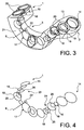
- a three-dimensional shape comprising an outer casing with two parallel and rectilinear extreme branches 1 and 2 and a median leg 3 in a portion of a circle connecting the preceding and perpendicular thereto.
- the figure 2 illustrates that this gearbox can be advantageously placed around a turbomachine 4, for example at the location of a high-pressure body thereof, by placing the end branches 1 and 2 in the axial direction of said turbomachine , to diametrically opposed generatrices, the middle branch 3 also running alongside the turbomachine 4 by making a U-turn around it.
- the drive take-off of the turbomachine can be done directly to from a conventional radial shaft belonging to the turbomachine 4, or via an intermediate shaft belonging to a separate housing and meshing with the radial shaft.
- Some possibilities of positions of the drive shaft (radial or intermediate) are indicated by the reference 9 to the figure 1 .
- the equipment 10 driven by the gear box can be mounted themselves on upper faces 6, peripheral 7 and front 8, and on radially outer faces 11 of the middle branch 3.
- the attachment of the gear box the turbomachine 4 can be made by bolting fastening points 12 located on the housing 13, possibly using shims or other intermediate supports between the turbomachine 4 and, for example, some of the inner faces 5 of the box .
- the equipment 10 is fixed to the casing 13 by other fixing points 12.
- the figure 3 shows that the gearbox is essentially composed of a housing 13 defining the contour of the three branches 1, 2 and 3, and a kinematic chain 14 contained in the housing 13 and in which one can distinguish three lines of gears 15, 16 and 17, respectively housed in a branch 1, 2 and 3 respectively.
- Each of them comprises generally toothed gears 18 meshing with each other to form spur gears, the axes 19 of some of these gears 18 being used to drive the moving parts of the equipment 10 in rotation through openings 20 of the casing 13.
- the number of toothed wheels 18, their diameters and gear ratios, as well as the positions of the openings 20 defining the motor axes 19 of the equipment 10 can be chosen relatively freely, depending on the speeds of rotation that are to be transmitted. and the positions of the equipment 10.
- a particular opening 21 is intended for the input of the drive shaft 9, which further comprises a drive pinion 22 meshing with any one of the toothed wheels 18.
- the figure 4 represents the kinematic chain 14 in isolated.
- the connection between the three gear lines 15, 16 and 17 is by junction gears 23 and 24 with non-parallel axes.
- Each of them may be composed of a first conical gear 25, integral and coaxial with an end gear 18 of the gear line 17, and a second conical gear 26, likewise integral and coaxial with an end gear 18 of one of the other gear lines 15 or 16.
- the connecting gears 23 and 24 thus ensure the continuity of the drive train 14 and the ability to move entirely by only the pinion gear 22. They also guide each of the gear lines 15, 16 and 17 in the direction of the branch 1, 2 or 3 of the housing 13.
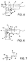
- flanges 29 define a junction interface between the housing portions 27 and 28 which extends in a plane intersecting the elbow, that is to say obliquely to the main directions of elongation of the branches 1 and 3, and precisely at the diagonal of the elbow.
- the junction of the bevel gears 25 and 26 then extends in this planar interface junction, so that the bevel gears 25 and 26 are flush with the opening of the housing portions 27 and 28 before assembly, and that, moreover, all the gears 18 may have parallel axes 17 inside each of the housing portions 27 and 28, each of the gear lines belonging to a separate housing portion.
- FIG. figure 6 Another advantageous embodiment is shown in FIG. figure 6 .
- the junction interface here extends parallel to the main faces of the branches 1 and 3, here in the plane of an inner face 31 of the branch 3, and instead of an end face of the branch 1, this interface junction being defined by flanges 30 similar to the previous ones.
- the advantage of this design is that the shapes of the crankcase portions, here 45 and 46, are devoid of regions beveled ends, and therefore they are simplified.
- the kinematic chain is divided into portions whose ends are flush with the junction interface, can be saved if the bevel gear junction gear defined by the bevel gears 25 and 26 is entirely in one of the branches, here 3, and that the kinematic chain 14 comprises a junction gear belonging to one of the gear lines (15 here) and formed of spur gears 18, noted here 18a and 18b , whose meshing junction 47 coincides with the junction interface 30.
- the slight disadvantage of this design is that the housing portion 46 contains a toothed wheel (18a) whose axis 19 has a direction different from that of the other , and therefore a slight complication is introduced here.
- a kinematically equivalent design would be to replace the bevel gears 25 and 26 by a spur gear 48 and a ring gear 49 on a plane, which represents the figure 7 , without any other details of the realization being modified.
Landscapes
- Engineering & Computer Science (AREA)
- General Engineering & Computer Science (AREA)
- Chemical & Material Sciences (AREA)
- Combustion & Propulsion (AREA)
- Mechanical Engineering (AREA)
- Transportation (AREA)
- General Details Of Gearings (AREA)
- Gear Transmission (AREA)
Applications Claiming Priority (2)
| Application Number | Priority Date | Filing Date | Title |
|---|---|---|---|
| FR1260242A FR2997467B1 (fr) | 2012-10-26 | 2012-10-26 | Boite d'engrenages de prise de mouvement sur une turbomachine, composee de carter assemble |
| PCT/FR2013/052545 WO2014064390A1 (fr) | 2012-10-26 | 2013-10-24 | Boite d'engrenages de prise de mouvement sur une turbomachine, composee de carter assemble |
Publications (2)
| Publication Number | Publication Date |
|---|---|
| EP2912291A1 EP2912291A1 (fr) | 2015-09-02 |
| EP2912291B1 true EP2912291B1 (fr) | 2016-07-20 |
Family
ID=47624303
Family Applications (1)
| Application Number | Title | Priority Date | Filing Date |
|---|---|---|---|
| EP13789880.5A Active EP2912291B1 (fr) | 2012-10-26 | 2013-10-24 | Boite d'engrenages de prise de mouvement sur une turbomachine, composee de carter assemble |
Country Status (11)
Families Citing this family (5)
| Publication number | Priority date | Publication date | Assignee | Title |
|---|---|---|---|---|
| FR2995053B1 (fr) * | 2012-09-03 | 2016-03-04 | Snecma | Boite d'engrenages de prise de mouvement sur une turbomachine, composee d'une chaine cinematique a lignes d'engrenages s'etendant dans des plans non paralleles |
| FR3012845B1 (fr) * | 2013-11-07 | 2015-10-23 | Snecma | Turbomachine equipee de moyens de reprise des efforts de poussee de son moteur |
| US10047827B2 (en) * | 2016-02-26 | 2018-08-14 | The Boeing Company | Low-profile, rotating-shaft transmission device, and associated method |
| US10502142B2 (en) * | 2017-04-11 | 2019-12-10 | United Technologies Corporation | Turbine engine gearbox assembly with sets of inline gears |
| FR3124545B1 (fr) * | 2021-06-28 | 2023-06-23 | Safran Aircraft Engines | Ensemble pour turbomachine d’aéronef comprenant un support d’équipements |
Family Cites Families (8)
| Publication number | Priority date | Publication date | Assignee | Title |
|---|---|---|---|---|
| US6142418A (en) * | 1998-05-12 | 2000-11-07 | Hamilton Sundstrand Corporation | Multi-path secondary power system for an aircraft |
| TWI223036B (en) * | 2002-03-22 | 2004-11-01 | Sumitomo Heavy Industries | Speed reduction device for gear reduction motor, gear reduction motor and products thereof |
| US7975465B2 (en) * | 2003-10-27 | 2011-07-12 | United Technologies Corporation | Hybrid engine accessory power system |
| US6840479B1 (en) * | 2003-12-05 | 2005-01-11 | The Boeing Company | Airframe mounted accessory drive (AMAD) power take-off shaft auxiliary power generation |
| US20120006137A1 (en) * | 2010-07-07 | 2012-01-12 | Hamilton Sundstrand Corporation | Gear driven accessory for gearbox |
| US8490411B2 (en) * | 2010-11-17 | 2013-07-23 | United Technologies Corporation | Axial accessory gearbox |
| US9068515B2 (en) * | 2011-12-07 | 2015-06-30 | United Technologies Corporation | Accessory gearbox with tower shaft removal capability |
| US8973465B2 (en) * | 2012-07-20 | 2015-03-10 | United Technologies Corporation | Gearbox for gas turbine engine |
-
2012
- 2012-10-26 FR FR1260242A patent/FR2997467B1/fr active Active
-
2013
- 2013-10-24 PL PL13789880.5T patent/PL2912291T3/pl unknown
- 2013-10-24 BR BR112015009233-0A patent/BR112015009233B1/pt not_active IP Right Cessation
- 2013-10-24 RU RU2015119673A patent/RU2639460C2/ru active
- 2013-10-24 WO PCT/FR2013/052545 patent/WO2014064390A1/fr active Application Filing
- 2013-10-24 US US14/437,030 patent/US9316158B2/en active Active
- 2013-10-24 EP EP13789880.5A patent/EP2912291B1/fr active Active
- 2013-10-24 CN CN201380056286.9A patent/CN104968917B/zh active Active
- 2013-10-24 CA CA2889030A patent/CA2889030C/en not_active Expired - Fee Related
- 2013-10-24 ES ES13789880.5T patent/ES2589114T3/es active Active
- 2013-10-24 JP JP2015538534A patent/JP6218846B2/ja not_active Expired - Fee Related
Also Published As
| Publication number | Publication date |
|---|---|
| US9316158B2 (en) | 2016-04-19 |
| RU2639460C2 (ru) | 2017-12-21 |
| CA2889030A1 (en) | 2014-05-01 |
| FR2997467B1 (fr) | 2016-07-29 |
| RU2015119673A (ru) | 2016-12-27 |
| CA2889030C (en) | 2019-11-05 |
| EP2912291A1 (fr) | 2015-09-02 |
| FR2997467A1 (fr) | 2014-05-02 |
| PL2912291T3 (pl) | 2016-12-30 |
| US20150285153A1 (en) | 2015-10-08 |
| ES2589114T3 (es) | 2016-11-10 |
| CN104968917A (zh) | 2015-10-07 |
| WO2014064390A1 (fr) | 2014-05-01 |
| JP6218846B2 (ja) | 2017-10-25 |
| CN104968917B (zh) | 2016-08-17 |
| JP2016500788A (ja) | 2016-01-14 |
| BR112015009233B1 (pt) | 2021-01-26 |
Similar Documents
| Publication | Publication Date | Title |
|---|---|---|
| EP2912291B1 (fr) | Boite d'engrenages de prise de mouvement sur une turbomachine, composee de carter assemble | |
| EP2893171B1 (fr) | Boite d'engrenages de prise de mouvement sur une turbomachine, composée d'une chaîne cinématique a lignes d'engrenages s'étendant dans des plans non parallèles | |
| EP3019771B1 (fr) | Intégration d'un train d'engrenages dans un voile de pignon de boîtier d'entraînement pour turbomachine | |
| FR2571112A1 (fr) | Transmission comportant des arbres de sortie doubles animes d'un mouvement de rotation en sens contraire | |
| FR3003323A1 (fr) | Fixation d'une boite d'engrenages en v sur une turbomachine | |
| FR2542835A1 (fr) | Convertisseur de couple de type axial planetaire | |
| CA2928696A1 (fr) | Turbomachine equipee de moyens de reprise des efforts de poussee de son moteur | |
| EP3356699A1 (fr) | Repartition de charges dans un reducteur de vitesse a deux lignes intermediaires de transmission | |
| FR2471505A1 (fr) | Servo-moteur actionne par fluide sous pression pour un dispositif de travail ou de transport | |
| EP2486298B1 (fr) | Dispositif d'accouplement pour la transmission d'un couple | |
| FR3014954A1 (fr) | Boite d'engrenages a fixer a une turbomachine comprenant une division de la chaine cinematique | |
| FR2994585A1 (fr) | Boite d'engrenages a encombrement reduit pour turbomachine d'aeronef | |
| FR2980546A1 (fr) | Dispositif de lubrification d'une boite d'engrenage par une came exentrique | |
| FR3047786B1 (fr) | Reducteur de vitesse a inversion de sens de rotation entree/sortie | |
| EP0765444B1 (fr) | Reducteur a excentriques | |
| EP2765463B1 (fr) | Mécanisme de transmission de mouvements axiaux et rotatifs entre deux axes décalés et pièce d'horlogerie comportant ce mécanisme | |
| FR2843060A1 (fr) | Dispositif d'entrainement pour machine-outil | |
| EP3333637A1 (fr) | Mouvement d'horlogerie mecanique a detection de reserve de marche | |
| EP3301329B1 (fr) | Réducteur épicycloïdal, bogie comprenant un tel réducteur et véhicule ferroviaire associé | |
| WO2014181069A1 (fr) | Integration de pompes a une boite d'engrenages annexe a un moteur d'aeronef | |
| FR2568340A1 (fr) | Train epicycloidal | |
| EP1659300A1 (fr) | Dispositif et procédé d'assemblage de deux arbres coaxiaux à rotation indépendante |
Legal Events
| Date | Code | Title | Description |
|---|---|---|---|
| PUAI | Public reference made under article 153(3) epc to a published international application that has entered the european phase |
Free format text: ORIGINAL CODE: 0009012 |
|
| 17P | Request for examination filed |
Effective date: 20150504 |
|
| AK | Designated contracting states |
Kind code of ref document: A1 Designated state(s): AL AT BE BG CH CY CZ DE DK EE ES FI FR GB GR HR HU IE IS IT LI LT LU LV MC MK MT NL NO PL PT RO RS SE SI SK SM TR |
|
| AX | Request for extension of the european patent |
Extension state: BA ME |
|
| RIN1 | Information on inventor provided before grant (corrected) |
Inventor name: PELTIER, JORDANE Inventor name: PRUNERA-USACH, STEPHANE |
|
| DAX | Request for extension of the european patent (deleted) | ||
| GRAP | Despatch of communication of intention to grant a patent |
Free format text: ORIGINAL CODE: EPIDOSNIGR1 |
|
| INTG | Intention to grant announced |
Effective date: 20160209 |
|
| GRAS | Grant fee paid |
Free format text: ORIGINAL CODE: EPIDOSNIGR3 |
|
| GRAA | (expected) grant |
Free format text: ORIGINAL CODE: 0009210 |
|
| AK | Designated contracting states |
Kind code of ref document: B1 Designated state(s): AL AT BE BG CH CY CZ DE DK EE ES FI FR GB GR HR HU IE IS IT LI LT LU LV MC MK MT NL NO PL PT RO RS SE SI SK SM TR |
|
| REG | Reference to a national code |
Ref country code: GB Ref legal event code: FG4D Free format text: NOT ENGLISH |
|
| REG | Reference to a national code |
Ref country code: CH Ref legal event code: EP |
|
| REG | Reference to a national code |
Ref country code: IE Ref legal event code: FG4D Free format text: LANGUAGE OF EP DOCUMENT: FRENCH |
|
| REG | Reference to a national code |
Ref country code: AT Ref legal event code: REF Ref document number: 814302 Country of ref document: AT Kind code of ref document: T Effective date: 20160815 |
|
| REG | Reference to a national code |
Ref country code: DE Ref legal event code: R096 Ref document number: 602013009707 Country of ref document: DE |
|
| REG | Reference to a national code |
Ref country code: SE Ref legal event code: TRGR |
|
| REG | Reference to a national code |
Ref country code: FR Ref legal event code: PLFP Year of fee payment: 4 |
|
| REG | Reference to a national code |
Ref country code: ES Ref legal event code: FG2A Ref document number: 2589114 Country of ref document: ES Kind code of ref document: T3 Effective date: 20161110 Ref country code: LT Ref legal event code: MG4D |
|
| REG | Reference to a national code |
Ref country code: NL Ref legal event code: MP Effective date: 20160720 |
|
| REG | Reference to a national code |
Ref country code: AT Ref legal event code: MK05 Ref document number: 814302 Country of ref document: AT Kind code of ref document: T Effective date: 20160720 |
|
| PG25 | Lapsed in a contracting state [announced via postgrant information from national office to epo] |
Ref country code: LT Free format text: LAPSE BECAUSE OF FAILURE TO SUBMIT A TRANSLATION OF THE DESCRIPTION OR TO PAY THE FEE WITHIN THE PRESCRIBED TIME-LIMIT Effective date: 20160720 Ref country code: IS Free format text: LAPSE BECAUSE OF FAILURE TO SUBMIT A TRANSLATION OF THE DESCRIPTION OR TO PAY THE FEE WITHIN THE PRESCRIBED TIME-LIMIT Effective date: 20161120 Ref country code: NO Free format text: LAPSE BECAUSE OF FAILURE TO SUBMIT A TRANSLATION OF THE DESCRIPTION OR TO PAY THE FEE WITHIN THE PRESCRIBED TIME-LIMIT Effective date: 20161020 Ref country code: FI Free format text: LAPSE BECAUSE OF FAILURE TO SUBMIT A TRANSLATION OF THE DESCRIPTION OR TO PAY THE FEE WITHIN THE PRESCRIBED TIME-LIMIT Effective date: 20160720 Ref country code: NL Free format text: LAPSE BECAUSE OF FAILURE TO SUBMIT A TRANSLATION OF THE DESCRIPTION OR TO PAY THE FEE WITHIN THE PRESCRIBED TIME-LIMIT Effective date: 20160720 Ref country code: RS Free format text: LAPSE BECAUSE OF FAILURE TO SUBMIT A TRANSLATION OF THE DESCRIPTION OR TO PAY THE FEE WITHIN THE PRESCRIBED TIME-LIMIT Effective date: 20160720 Ref country code: HR Free format text: LAPSE BECAUSE OF FAILURE TO SUBMIT A TRANSLATION OF THE DESCRIPTION OR TO PAY THE FEE WITHIN THE PRESCRIBED TIME-LIMIT Effective date: 20160720 |
|
| PG25 | Lapsed in a contracting state [announced via postgrant information from national office to epo] |
Ref country code: LV Free format text: LAPSE BECAUSE OF FAILURE TO SUBMIT A TRANSLATION OF THE DESCRIPTION OR TO PAY THE FEE WITHIN THE PRESCRIBED TIME-LIMIT Effective date: 20160720 Ref country code: PT Free format text: LAPSE BECAUSE OF FAILURE TO SUBMIT A TRANSLATION OF THE DESCRIPTION OR TO PAY THE FEE WITHIN THE PRESCRIBED TIME-LIMIT Effective date: 20161121 Ref country code: BE Free format text: LAPSE BECAUSE OF NON-PAYMENT OF DUE FEES Effective date: 20161031 Ref country code: AT Free format text: LAPSE BECAUSE OF FAILURE TO SUBMIT A TRANSLATION OF THE DESCRIPTION OR TO PAY THE FEE WITHIN THE PRESCRIBED TIME-LIMIT Effective date: 20160720 Ref country code: GR Free format text: LAPSE BECAUSE OF FAILURE TO SUBMIT A TRANSLATION OF THE DESCRIPTION OR TO PAY THE FEE WITHIN THE PRESCRIBED TIME-LIMIT Effective date: 20161021 |
|
| REG | Reference to a national code |
Ref country code: DE Ref legal event code: R097 Ref document number: 602013009707 Country of ref document: DE |
|
| PG25 | Lapsed in a contracting state [announced via postgrant information from national office to epo] |
Ref country code: RO Free format text: LAPSE BECAUSE OF FAILURE TO SUBMIT A TRANSLATION OF THE DESCRIPTION OR TO PAY THE FEE WITHIN THE PRESCRIBED TIME-LIMIT Effective date: 20160720 Ref country code: EE Free format text: LAPSE BECAUSE OF FAILURE TO SUBMIT A TRANSLATION OF THE DESCRIPTION OR TO PAY THE FEE WITHIN THE PRESCRIBED TIME-LIMIT Effective date: 20160720 |
|
| PLBE | No opposition filed within time limit |
Free format text: ORIGINAL CODE: 0009261 |
|
| STAA | Information on the status of an ep patent application or granted ep patent |
Free format text: STATUS: NO OPPOSITION FILED WITHIN TIME LIMIT |
|
| PG25 | Lapsed in a contracting state [announced via postgrant information from national office to epo] |
Ref country code: DK Free format text: LAPSE BECAUSE OF FAILURE TO SUBMIT A TRANSLATION OF THE DESCRIPTION OR TO PAY THE FEE WITHIN THE PRESCRIBED TIME-LIMIT Effective date: 20160720 Ref country code: CZ Free format text: LAPSE BECAUSE OF FAILURE TO SUBMIT A TRANSLATION OF THE DESCRIPTION OR TO PAY THE FEE WITHIN THE PRESCRIBED TIME-LIMIT Effective date: 20160720 Ref country code: SK Free format text: LAPSE BECAUSE OF FAILURE TO SUBMIT A TRANSLATION OF THE DESCRIPTION OR TO PAY THE FEE WITHIN THE PRESCRIBED TIME-LIMIT Effective date: 20160720 Ref country code: BG Free format text: LAPSE BECAUSE OF FAILURE TO SUBMIT A TRANSLATION OF THE DESCRIPTION OR TO PAY THE FEE WITHIN THE PRESCRIBED TIME-LIMIT Effective date: 20161020 Ref country code: SM Free format text: LAPSE BECAUSE OF FAILURE TO SUBMIT A TRANSLATION OF THE DESCRIPTION OR TO PAY THE FEE WITHIN THE PRESCRIBED TIME-LIMIT Effective date: 20160720 |
|
| REG | Reference to a national code |
Ref country code: CH Ref legal event code: PL |
|
| 26N | No opposition filed |
Effective date: 20170421 |
|
| REG | Reference to a national code |
Ref country code: IE Ref legal event code: MM4A |
|
| PG25 | Lapsed in a contracting state [announced via postgrant information from national office to epo] |
Ref country code: LI Free format text: LAPSE BECAUSE OF NON-PAYMENT OF DUE FEES Effective date: 20161031 Ref country code: CH Free format text: LAPSE BECAUSE OF NON-PAYMENT OF DUE FEES Effective date: 20161031 |
|
| REG | Reference to a national code |
Ref country code: FR Ref legal event code: CD Owner name: HISPANO SUIZA, FR Effective date: 20170725 |
|
| PG25 | Lapsed in a contracting state [announced via postgrant information from national office to epo] |
Ref country code: LU Free format text: LAPSE BECAUSE OF NON-PAYMENT OF DUE FEES Effective date: 20161024 Ref country code: SI Free format text: LAPSE BECAUSE OF FAILURE TO SUBMIT A TRANSLATION OF THE DESCRIPTION OR TO PAY THE FEE WITHIN THE PRESCRIBED TIME-LIMIT Effective date: 20160720 |
|
| REG | Reference to a national code |
Ref country code: FR Ref legal event code: PLFP Year of fee payment: 5 |
|
| PG25 | Lapsed in a contracting state [announced via postgrant information from national office to epo] |
Ref country code: IE Free format text: LAPSE BECAUSE OF NON-PAYMENT OF DUE FEES Effective date: 20161024 |
|
| REG | Reference to a national code |
Ref country code: BE Ref legal event code: MM Effective date: 20161031 |
|
| PG25 | Lapsed in a contracting state [announced via postgrant information from national office to epo] |
Ref country code: HU Free format text: LAPSE BECAUSE OF FAILURE TO SUBMIT A TRANSLATION OF THE DESCRIPTION OR TO PAY THE FEE WITHIN THE PRESCRIBED TIME-LIMIT; INVALID AB INITIO Effective date: 20131024 |
|
| PG25 | Lapsed in a contracting state [announced via postgrant information from national office to epo] |
Ref country code: MT Free format text: LAPSE BECAUSE OF FAILURE TO SUBMIT A TRANSLATION OF THE DESCRIPTION OR TO PAY THE FEE WITHIN THE PRESCRIBED TIME-LIMIT Effective date: 20160720 Ref country code: CY Free format text: LAPSE BECAUSE OF FAILURE TO SUBMIT A TRANSLATION OF THE DESCRIPTION OR TO PAY THE FEE WITHIN THE PRESCRIBED TIME-LIMIT Effective date: 20160720 Ref country code: MK Free format text: LAPSE BECAUSE OF FAILURE TO SUBMIT A TRANSLATION OF THE DESCRIPTION OR TO PAY THE FEE WITHIN THE PRESCRIBED TIME-LIMIT Effective date: 20160720 Ref country code: MC Free format text: LAPSE BECAUSE OF FAILURE TO SUBMIT A TRANSLATION OF THE DESCRIPTION OR TO PAY THE FEE WITHIN THE PRESCRIBED TIME-LIMIT Effective date: 20160720 |
|
| REG | Reference to a national code |
Ref country code: FR Ref legal event code: PLFP Year of fee payment: 6 |
|
| PG25 | Lapsed in a contracting state [announced via postgrant information from national office to epo] |
Ref country code: TR Free format text: LAPSE BECAUSE OF FAILURE TO SUBMIT A TRANSLATION OF THE DESCRIPTION OR TO PAY THE FEE WITHIN THE PRESCRIBED TIME-LIMIT Effective date: 20160720 Ref country code: AL Free format text: LAPSE BECAUSE OF FAILURE TO SUBMIT A TRANSLATION OF THE DESCRIPTION OR TO PAY THE FEE WITHIN THE PRESCRIBED TIME-LIMIT Effective date: 20160720 |
|
| PGFP | Annual fee paid to national office [announced via postgrant information from national office to epo] |
Ref country code: PL Payment date: 20200921 Year of fee payment: 8 Ref country code: SE Payment date: 20200923 Year of fee payment: 8 |
|
| PGFP | Annual fee paid to national office [announced via postgrant information from national office to epo] |
Ref country code: IT Payment date: 20200917 Year of fee payment: 8 Ref country code: ES Payment date: 20201102 Year of fee payment: 8 |
|
| REG | Reference to a national code |
Ref country code: SE Ref legal event code: EUG |
|
| PG25 | Lapsed in a contracting state [announced via postgrant information from national office to epo] |
Ref country code: SE Free format text: LAPSE BECAUSE OF NON-PAYMENT OF DUE FEES Effective date: 20211025 |
|
| PG25 | Lapsed in a contracting state [announced via postgrant information from national office to epo] |
Ref country code: IT Free format text: LAPSE BECAUSE OF NON-PAYMENT OF DUE FEES Effective date: 20211024 |
|
| REG | Reference to a national code |
Ref country code: ES Ref legal event code: FD2A Effective date: 20230217 |
|
| PG25 | Lapsed in a contracting state [announced via postgrant information from national office to epo] |
Ref country code: ES Free format text: LAPSE BECAUSE OF NON-PAYMENT OF DUE FEES Effective date: 20211025 |
|
| PG25 | Lapsed in a contracting state [announced via postgrant information from national office to epo] |
Ref country code: PL Free format text: LAPSE BECAUSE OF NON-PAYMENT OF DUE FEES Effective date: 20211024 |
|
| PGFP | Annual fee paid to national office [announced via postgrant information from national office to epo] |
Ref country code: GB Payment date: 20240919 Year of fee payment: 12 |
|
| PGFP | Annual fee paid to national office [announced via postgrant information from national office to epo] |
Ref country code: FR Payment date: 20240919 Year of fee payment: 12 |
|
| PGFP | Annual fee paid to national office [announced via postgrant information from national office to epo] |
Ref country code: DE Payment date: 20240919 Year of fee payment: 12 |