EP2912283B1 - An alignment device for a turbomachine component and turbomachine including such device - Google Patents
An alignment device for a turbomachine component and turbomachine including such device Download PDFInfo
- Publication number
- EP2912283B1 EP2912283B1 EP13759506.2A EP13759506A EP2912283B1 EP 2912283 B1 EP2912283 B1 EP 2912283B1 EP 13759506 A EP13759506 A EP 13759506A EP 2912283 B1 EP2912283 B1 EP 2912283B1
- Authority
- EP
- European Patent Office
- Prior art keywords
- turbomachine
- component
- baseplate
- hole
- threaded
- Prior art date
- Legal status (The legal status is an assumption and is not a legal conclusion. Google has not performed a legal analysis and makes no representation as to the accuracy of the status listed.)
- Not-in-force
Links
- 230000001105 regulatory effect Effects 0.000 claims description 55
- 230000000903 blocking effect Effects 0.000 claims description 19
- 238000000034 method Methods 0.000 claims description 9
- 230000008878 coupling Effects 0.000 claims description 4
- 238000010168 coupling process Methods 0.000 claims description 4
- 238000005859 coupling reaction Methods 0.000 claims description 4
- 238000010586 diagram Methods 0.000 description 1
- 230000000694 effects Effects 0.000 description 1
- 238000009434 installation Methods 0.000 description 1
- 230000013011 mating Effects 0.000 description 1
- 238000005259 measurement Methods 0.000 description 1
- 238000004806 packaging method and process Methods 0.000 description 1
Images
Classifications
-
- F—MECHANICAL ENGINEERING; LIGHTING; HEATING; WEAPONS; BLASTING
- F01—MACHINES OR ENGINES IN GENERAL; ENGINE PLANTS IN GENERAL; STEAM ENGINES
- F01D—NON-POSITIVE DISPLACEMENT MACHINES OR ENGINES, e.g. STEAM TURBINES
- F01D25/00—Component parts, details, or accessories, not provided for in, or of interest apart from, other groups
- F01D25/28—Supporting or mounting arrangements, e.g. for turbine casing
-
- B—PERFORMING OPERATIONS; TRANSPORTING
- B23—MACHINE TOOLS; METAL-WORKING NOT OTHERWISE PROVIDED FOR
- B23P—METAL-WORKING NOT OTHERWISE PROVIDED FOR; COMBINED OPERATIONS; UNIVERSAL MACHINE TOOLS
- B23P19/00—Machines for simply fitting together or separating metal parts or objects, or metal and non-metal parts, whether or not involving some deformation; Tools or devices therefor so far as not provided for in other classes
- B23P19/10—Aligning parts to be fitted together
-
- F—MECHANICAL ENGINEERING; LIGHTING; HEATING; WEAPONS; BLASTING
- F01—MACHINES OR ENGINES IN GENERAL; ENGINE PLANTS IN GENERAL; STEAM ENGINES
- F01D—NON-POSITIVE DISPLACEMENT MACHINES OR ENGINES, e.g. STEAM TURBINES
- F01D25/00—Component parts, details, or accessories, not provided for in, or of interest apart from, other groups
- F01D25/24—Casings; Casing parts, e.g. diaphragms, casing fastenings
-
- F—MECHANICAL ENGINEERING; LIGHTING; HEATING; WEAPONS; BLASTING
- F05—INDEXING SCHEMES RELATING TO ENGINES OR PUMPS IN VARIOUS SUBCLASSES OF CLASSES F01-F04
- F05D—INDEXING SCHEME FOR ASPECTS RELATING TO NON-POSITIVE-DISPLACEMENT MACHINES OR ENGINES, GAS-TURBINES OR JET-PROPULSION PLANTS
- F05D2230/00—Manufacture
- F05D2230/60—Assembly methods
- F05D2230/64—Assembly methods using positioning or alignment devices for aligning or centring, e.g. pins
-
- F—MECHANICAL ENGINEERING; LIGHTING; HEATING; WEAPONS; BLASTING
- F05—INDEXING SCHEMES RELATING TO ENGINES OR PUMPS IN VARIOUS SUBCLASSES OF CLASSES F01-F04
- F05D—INDEXING SCHEME FOR ASPECTS RELATING TO NON-POSITIVE-DISPLACEMENT MACHINES OR ENGINES, GAS-TURBINES OR JET-PROPULSION PLANTS
- F05D2260/00—Function
- F05D2260/30—Retaining components in desired mutual position
-
- Y—GENERAL TAGGING OF NEW TECHNOLOGICAL DEVELOPMENTS; GENERAL TAGGING OF CROSS-SECTIONAL TECHNOLOGIES SPANNING OVER SEVERAL SECTIONS OF THE IPC; TECHNICAL SUBJECTS COVERED BY FORMER USPC CROSS-REFERENCE ART COLLECTIONS [XRACs] AND DIGESTS
- Y10—TECHNICAL SUBJECTS COVERED BY FORMER USPC
- Y10T—TECHNICAL SUBJECTS COVERED BY FORMER US CLASSIFICATION
- Y10T29/00—Metal working
- Y10T29/49—Method of mechanical manufacture
- Y10T29/49316—Impeller making
- Y10T29/4932—Turbomachine making
-
- Y—GENERAL TAGGING OF NEW TECHNOLOGICAL DEVELOPMENTS; GENERAL TAGGING OF CROSS-SECTIONAL TECHNOLOGIES SPANNING OVER SEVERAL SECTIONS OF THE IPC; TECHNICAL SUBJECTS COVERED BY FORMER USPC CROSS-REFERENCE ART COLLECTIONS [XRACs] AND DIGESTS
- Y10—TECHNICAL SUBJECTS COVERED BY FORMER USPC
- Y10T—TECHNICAL SUBJECTS COVERED BY FORMER US CLASSIFICATION
- Y10T29/00—Metal working
- Y10T29/53—Means to assemble or disassemble
Definitions
- the present invention relates to an alignment device for accurately aligning a component of a turbomachine with respect to a baseplate and rotation axis of the turbomachine.
- typical components include baseplate, inlet and exhaust plena, turbocompressor, combustor and gas turbine.
- the position of plena, combustor and rotating components is normally defined with respect to the baseplate in order to achieve the correct alignment along the rotation axis.
- Alignment of the inlet plenum is particularly challenging due to the dimension and weight of the carpentry.
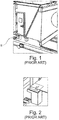
- plenum 100 is placed on a plurality of supports 110 provided on the baseplate B.
- Vertical alignment of the plenum 100 is achieved through a plurality of shims 120 respectively placed between a plenum base plate 105 and the supports 110.
- Lateral alignment is achieved through screws (not shown) operated for regulation from outside the plenum 100.
- the main disadvantages of the above solution derives from the fact that, in order to achieve the desired vertical alignment, shims 120 have to be positioned below the plenum 100 after the plenum 100 is placed on the supports 110. This results in complex and time-demanding alignment operation.
- alignment and checking operations must be performed separately, i.e. the alignment has to be checked after one or more of the shims 120 are placed. If the alignment is not acceptable, shims 120 have to be changed or modified. After such regulations, checking operations have to be performed again. Shims regulation and position checking have to be alternated till a satisfactory alignment result is achieved.
- US 2009/014621 A1 describes a mount assembly for securing a machine base to a foundation including: a first block secured to the machine base and a second block secured to the foundation.
- First and second blocks can be aligned horizontal with the use of bolts and vertically with the use of a flat shim plate.
- US 2005/086788 A1 describes a tooling system including a workstation assembly and a toolkit, is for performing an operation on a valve assembly.
- the present invention accomplish such an object by providing a turbomachine including a component fixedly constrainable to a baseplate of said turbomachine and an alignment device for regulating the position of said component with respect to the baseplate, wherein the alignment device includes at least a first bolt a second bolt and a third bolt, each bolt including a regulating screw respectively coupled with a threaded through hole in said component, each threaded hole defining a respective alignment axis for said component, each screw having a respective axial end which is susceptible of contacting said baseplate for defining the position of the component along each axis respectively, each bolt including a blocking nut for respectively blocking said regulating screws in said threaded holes; the alignment device further includes a fourth fixing screw which is screwable in a threaded hole of the baseplate (B) for fixing said component to the baseplate.
- One of the regulating screws of one of said bolts has a through hole coaxial with the respective alignment axis for housing said fourth fixing screw.
- the component of the turbomachine includes an inner cavity, said regulating screws of said bolts and said fixing screw being operatable from inside said inner cavity for respectively defining the position of the component and for fixing said component to the baseplate.
- the solution of the present invention allows to:
- the present invention provides an alignment device for regulating the position of a component of a turbomachine with respect to a baseplate of the turbomachine, wherein the alignment device includes at least a first bolt a second bolt and a third bolt, each bolt including a regulating screw respectively coupled with a threaded through hole in said component, each threaded hole defining a respective alignment axis for said component, each screw having a respective axial end which is susceptible of contacting said baseplate for defining the position of the component along each axis respectively, each bolt including a nut for respectively blocking said regulating screws in said threaded holes; the alignment device further includes a fourth fixing screw which is screwable in a threaded hole of the baseplate for fixing said component to the baseplate.
- One of the regulating screws of one of said bolts has a through hole coaxial with the respective alignment axis for housing said fourth fixing screw.
- the alignment device of the present invention allows to quickly and efficiently position components of a turbomachine with respect to the turbomachine baseplate, in order to correct align each component along the turbomachine rotation axis. Particularly, albeit not exclusively, such an alignment device is usable to align large and heavy components, like the inlet plenum in a gas turbine machine.
- the present invention provides a method for regulating the position of a component of a turbomachine with respect to a baseplate of the turbomachine, wherein the alignment method includes the steps of:
- One of the regulating screws of one of said bolts is provided with a through hole coaxial with the respective alignment axis for housing the fourth fixing screw, and the alignment method further including the step of inserting the fourth fixing screw in the through hole of the regulating screw before screwing the fourth fixing screw in the threaded hole of the baseplate (B).
- a first and a second embodiment of the present invention are shown in figures 3 to 6 .
- a turbomachine 200 comprise a baseplate B and a plurality of components directly or indirectly fixable to the baseplate B in order to be correctly aligned along an axis of rotation W of the turbomachine 200.
- the turbomachine 200 is constituted by a gas turbine machine, whose components include an inlet plenum 100, a compressor 150, a combustor 160, a gas turbine 170 and an outlet plenum (not shown). Both the compressor 150 and the turbine 170 includes rotors which rotate around axis W.
- the present invention is also applicable to other types of turbomachine, whenever a component of the turbomachine 200 has to be fixedly constrained to the baseplate B by means of an alignment device 10 having the characteristics described in the following.
- the alignment device 10 is at least associated with the inlet plenum 100, for regulating the position of the inlet plenum 100 with respect to the baseplate B.
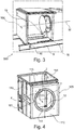
- the inlet plenum 100 comprises a rectangular base 111, a front wall 112 having a circular aperture 116, a rear wall 113 opposite to the front wall 112 and two lateral walls 114, 115, extending between the front and the rear walls 112, 113.
- the four walls 112, 113, 114, 115 are orthogonal to the base 111, each wall extending from a respective edge of the base 111.
- the volume comprised between the base 111 and the walls 112, 113, 114, 115 defines a parallelepiped-shaped cavity 101.
- the turbomachine 200 comprises four alignment devices 10 (only three alignment devices 10 are visible in figure 3 ) for regulating the position of the inlet plenum 100 with respect to the baseplate B, in such a way that the circular aperture 116 is aligned with the rotation axis W. This assures a correct coupling between the inlet plenum 100 and an inlet section 151 of the compressor 150.
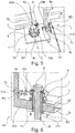
- Figures 5 and 6 show the corner between the base 111 and the front and lateral walls 112, 114 of the inlet plenum 100, including one of the four alignment devices 10 for aligning the plenum 100 with respect to the baseplate B.
- the description which follows will be referred to the alignment device of figures 5 and 6 .
- Each of the other three alignment devices 10 are identical to that of figures 5 and 6 , each being different from the others only for position and orientation.
- Each alignment device 10 includes a first bolt 3a, a second bolt 3b and a third bolt 1, each bolt 3a, 3b, 1 including a respective regulating screw 30a, 30b, 30c respectively coupled with a threaded through hole 7a, 7b, 7c provided in the inlet plenum 100 in the walls and in the base 111 of the inlet plenum 100.
- the threaded through hole 7a, 7b respectively coupled with the regulating screws 30a, 30b of the first and second bolt 3a, 3b are provided in the lateral wall 114 and in the rear wall 113, respectively.
- threaded through hole 7c coupled with the regulating screw 30c of the third bolt 1 is provided in the base 111.
- Each threaded through hole 7a, 7b, 7c defines a respective alignment axis X, Y, Z for the inlet plenum 100.
- the alignment axes X, Y, Z are mutually orthogonal, the axes X, Y of the first and second bolt 3a, 3b being oriented horizontally, i.e. parallel to the baseplate B, the axis Z of the third bolt 1 being oriented vertically, i.e. orthogonally to the baseplate B.
- the axis X of the first bolt is orthogonal to the rotation axis W and the axis Y is parallel to the rotation axis W.
- the regulating screws 30a, 30b, 30c are inserted in the respective threaded through hole 7a, 7b, 7c in such a way that each screw head is placed in the cavity 101.
- Each of the screws 30a, 30b, 30c can be therefore operated by an operator standing inside the inlet plenum 100, i.e. in the cavity 101.
- each screw 30a, 30b, 30c has a respective axial end 31a, 31b, 31c which is susceptible of protruding outside the inlet plenum 100 when each screw is coupled with the respective through hole 7a, 7b, 7c.
- Each axial end 31a, 31b, 31c contacts a respective surface B1, B2, B3, provided in the baseplate B and oriented orthogonally to the alignment axes X, Y, Z, respectively.
- the length of the portion of each screw 30a, 30b, 30c which protrudes outside the inlet plenum 100 defines the distance of the inlet plenum 100, along each alignment axis X, Y, Z, from the surfaces B1, B2, B3 of the baseplate B, respectively.
- Each bolt 3a, 3b, 1 includes a blocking nut 4a, 4b, 4c for respectively blocking each regulating screw 30a, 30b, 30c in the respective threaded hole 7a, 7b, 7c.
- Each blocking nut 4a, 4b, 4c is coupled with a respective portion of each regulating screw 30a, 30b, 30c immediately under the head thereof.
- each screw 30a, 30b, 30c is respectively coupled with the respective through hole 7a, 7b, 7c
- each nut 4a, 4b, 4c is operatable from inside the cavity 101 to be screwed against the wall 112, 113, 114, 115 or base 111 of the inlet plenum 100 which is provided with the threaded through hole 7a, 7b, 7c, respectively.
- an operator While standing inside the cavity 101, an operator can easily regulate the screws 30a, 30b, 30c, thus regulating the position of the inlet plenum 100 along each alignment axis X, Y, Z. From the same standing position, after checking the position of the inlet plenum 100, the operator can easily block each regulating screw 30a, 30b, 30c through the respective blocking nut 4a, 4b, 4c, thus defining the position of the inlet plenum 100 along each alignment axis X, Y, Z.
- the first and second bolt 3a, 3b are of the conventional type.
- the third bolt 1 comprises a longitudinal through hole 40 in the regulating screw 30c, which is coaxial with the respective alignment axis Z when the respective screw 30c is coupled with the respective through hole 7c.
- the hole 40 houses a fourth fixing screw 5 which is couplable with a threaded hole 50 provided in the surface B3 of the baseplate B for fixing the position of the inlet plenum 100 with respect to the baseplate B.
- the diameter of the through hole 40 is slightly greater than the diameter of the fourth fixing screw 5 (for example, the difference between the diameters of this hole and this screw is a value in the range of 10-20 mm), in order to allow sufficient lateral (i.e. X and Y) movement (e.g. +/- 5-10 mm) of the inlet plenum during alignment.
- the head of the fourth fixing screw 5 is operatable from inside the cavity 101.
- a washer 6 is provided between the head of the regulating screw 30c and the head of the fixing screw 5 in order to provide a convenient mating surface between the fourth fixing screw 5 and the third bolt 1.
- the operator While standing inside the cavity 101 and after block each regulating screw 30a, 30b, 30c through the respective blocking nut 4a, 4b, 4c, the operator can also fix the position of the inlet plenum 100 with respect to the base plate B, by screwing the fourth fixing screw 5 in the threaded hole 50.
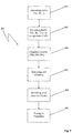
- an alignment method 300 for regulating the position of the inlet plenum 100 includes:
- one end of the shank of the screw 30c abuts on the surface B3 of the baseplate B; in this way, by screwing/unscrewing the screw 30c the position of the plenum 100 is regulated with respect to the baseplate B.
- the plenum 10 is fixed to the baseplate B by means of the screw 5 and the hole 50.
- the regulating screw e.g. screw 30c
- the fixing screw is external to the regulating screw; they are typically parallel to each other; the inlet plenum is provided with a non-threaded through hole for the fixing screw distinct from the through hole for the regulating screw; typically, they are close to each other and parallel to each other; the diameter of the fixing screw through hole is slightly greater than the diameter of the fixing screw (for example, the difference between the diameters of this hole and this screw is a value in the range of 10-20 mm), in order to allow sufficient lateral (i.e.
Landscapes
- Engineering & Computer Science (AREA)
- Mechanical Engineering (AREA)
- General Engineering & Computer Science (AREA)
- Structures Of Non-Positive Displacement Pumps (AREA)
- Connection Of Plates (AREA)
Description
- The present invention relates to an alignment device for accurately aligning a component of a turbomachine with respect to a baseplate and rotation axis of the turbomachine.
- Typically, when packaging a turbomachine, all the components have to be aligned with respect to the turbomachine rotation axis. Correct positioning of the components is very important because an incorrect alignment can result in internal flow distortion, high vibrations and potential damage to machinery due to mechanical contact between turbomachinery and other components.
- In a gas turbine turbomachine installation typical components include baseplate, inlet and exhaust plena, turbocompressor, combustor and gas turbine. The position of plena, combustor and rotating components is normally defined with respect to the baseplate in order to achieve the correct alignment along the rotation axis.
- Alignment of the inlet plenum is particularly challenging due to the dimension and weight of the carpentry.
- With reference to
figures 1 and 2 , in a knownsolution plenum 100 is placed on a plurality of supports 110 provided on the baseplate B. Vertical alignment of theplenum 100 is achieved through a plurality of shims 120 respectively placed between a plenum base plate 105 and the supports 110. Lateral alignment is achieved through screws (not shown) operated for regulation from outside theplenum 100. - The main disadvantages of the above solution derives from the fact that, in order to achieve the desired vertical alignment, shims 120 have to be positioned below the
plenum 100 after theplenum 100 is placed on the supports 110. This results in complex and time-demanding alignment operation. In addition, alignment and checking operations must be performed separately, i.e. the alignment has to be checked after one or more of the shims 120 are placed. If the alignment is not acceptable, shims 120 have to be changed or modified. After such regulations, checking operations have to be performed again. Shims regulation and position checking have to be alternated till a satisfactory alignment result is achieved. - It would be desirable to provide an improved alignment device for accurately aligning a component of a turbomachine with respect to a baseplate of the turbomachine, thus avoiding the above inconveniencies.
- It would also be desirable to such alignment condition is firm and maintained in time even during operation of the turbomachine.
-
US 2009/014621 A1 describes a mount assembly for securing a machine base to a foundation including: a first block secured to the machine base and a second block secured to the foundation. First and second blocks can be aligned horizontal with the use of bolts and vertically with the use of a flat shim plate. -
US 2005/086788 A1 describes a tooling system including a workstation assembly and a toolkit, is for performing an operation on a valve assembly. - The invention is defined by the independent claims. In the following description, anything referred to as an embodiment which does not fall within the scope of the claims is to be understood as an example useful for understanding the invention.
- According to a first embodiment, the present invention accomplish such an object by providing a turbomachine including a component fixedly constrainable to a baseplate of said turbomachine and an alignment device for regulating the position of said component with respect to the baseplate, wherein the alignment device includes at least a first bolt a second bolt and a third bolt, each bolt including a regulating screw respectively coupled with a threaded through hole in said component, each threaded hole defining a respective alignment axis for said component, each screw having a respective axial end which is susceptible of contacting said baseplate for defining the position of the component along each axis respectively, each bolt including a blocking nut for respectively blocking said regulating screws in said threaded holes; the alignment device further includes a fourth fixing screw which is screwable in a threaded hole of the baseplate (B) for fixing said component to the baseplate.
- One of the regulating screws of one of said bolts has a through hole coaxial with the respective alignment axis for housing said fourth fixing screw.
- According to a further advantageous feature of the first embodiment, the component of the turbomachine includes an inner cavity, said regulating screws of said bolts and said fixing screw being operatable from inside said inner cavity for respectively defining the position of the component and for fixing said component to the baseplate.
- The solution of the present invention allows to:
- correctly align the component of the turbomachine without requiring additional parts (shims) to be placed between the component and the baseplate of the turbomachine;
- perform quicker and easier operations, as checking activities can be performed during alignment operation;
- perform both the alignment and measurements from the inside the component.
- In a second embodiment, the present invention provides an alignment device for regulating the position of a component of a turbomachine with respect to a baseplate of the turbomachine, wherein the alignment device includes at least a first bolt a second bolt and a third bolt, each bolt including a regulating screw respectively coupled with a threaded through hole in said component, each threaded hole defining a respective alignment axis for said component, each screw having a respective axial end which is susceptible of contacting said baseplate for defining the position of the component along each axis respectively, each bolt including a nut for respectively blocking said regulating screws in said threaded holes; the alignment device further includes a fourth fixing screw which is screwable in a threaded hole of the baseplate for fixing said component to the baseplate. One of the regulating screws of one of said bolts has a through hole coaxial with the respective alignment axis for housing said fourth fixing screw.
- The alignment device of the present invention allows to quickly and efficiently position components of a turbomachine with respect to the turbomachine baseplate, in order to correct align each component along the turbomachine rotation axis. Particularly, albeit not exclusively, such an alignment device is usable to align large and heavy components, like the inlet plenum in a gas turbine machine.
- According to a third embodiment, the present invention provides a method for regulating the position of a component of a turbomachine with respect to a baseplate of the turbomachine, wherein the alignment method includes the steps of:
- providing at least a first bolt a second bolt and a third bolt, each bolt including a regulating screw and a blocking nut, as well as a fourth fixing screw,
- providing in said component at least a first threaded through hole, a second threaded through hole and a third threaded through hole each threaded hole defining a respective alignment axis for said component, each threaded hole having the same diameter of said first, second and third bolts, respectively
- coupling each regulating screw of said first, second and third bolts with said first, second and third threaded through hole, respectively, as well as, in said baseplate, a threaded hole,
- screwing the regulating screws in the threaded through holes in such a way that a respective axial end of each screw contacts said baseplate for defining the position of the component along each axis respectively,
- blocking said regulating screws in said threaded through holes with said blocking nut, respectively,
- screwing the fourth fixing screw in the threaded hole of the baseplate thereby fixing the component to the baseplate.
- One of the regulating screws of one of said bolts is provided with a through hole coaxial with the respective alignment axis for housing the fourth fixing screw, and the alignment method further including the step of inserting the fourth fixing screw in the through hole of the regulating screw before screwing the fourth fixing screw in the threaded hole of the baseplate (B).
- The same advantages described above with reference to the first and second embodiment of the present invention are accomplished by this third embodiment.
- Other objects, features and advantages of the present invention will become evident from the following description of the embodiments of the invention taken in conjunction with the following drawings, wherein:
-
Figure 1 is a perspective view of a conventional and known-in-the-art alignment device for a component of a turbomachine; -
Figure 2 is an enlarged view of the detail II shown infigure 1 ; -
Figure 3 is a perspective view showing a turbomachine according to the present invention; -
Figure 4 is a perspective view showing a component of the turbomachine ofFigure 3 ; -
Figures 5 is a detailed view of the component ofFigure 4 , showing an alignment device according to the present invention; -
Figure 6 is a more view of the alignment device ofFigure 5 ; -
Figure 7 is a block diagram schematically showing an alignment method according to the present invention. - A first and a second embodiment of the present invention are shown in
figures 3 to 6 . - With reference to
figure 3 , aturbomachine 200 comprise a baseplate B and a plurality of components directly or indirectly fixable to the baseplate B in order to be correctly aligned along an axis of rotation W of theturbomachine 200. - In the embodiment of
figure 3 theturbomachine 200 is constituted by a gas turbine machine, whose components include aninlet plenum 100, a compressor 150, a combustor 160, a gas turbine 170 and an outlet plenum (not shown). Both the compressor 150 and the turbine 170 includes rotors which rotate around axis W. - In general, according to other embodiments (not shown), the present invention is also applicable to other types of turbomachine, whenever a component of the
turbomachine 200 has to be fixedly constrained to the baseplate B by means of analignment device 10 having the characteristics described in the following. - In the
gas turbine turbomachine 200 offigure 3 , thealignment device 10 is at least associated with theinlet plenum 100, for regulating the position of theinlet plenum 100 with respect to the baseplate B. - With reference to
figure 4 , theinlet plenum 100 comprises arectangular base 111, afront wall 112 having a circular aperture 116, arear wall 113 opposite to thefront wall 112 and twolateral walls rear walls walls base 111, each wall extending from a respective edge of thebase 111. In theinlet plenum 100, the volume comprised between thebase 111 and thewalls shaped cavity 101. - At the four corners of the
base 111 of theinlet plenum 100, theturbomachine 200 comprises four alignment devices 10 (only threealignment devices 10 are visible infigure 3 ) for regulating the position of theinlet plenum 100 with respect to the baseplate B, in such a way that the circular aperture 116 is aligned with the rotation axis W. This assures a correct coupling between theinlet plenum 100 and an inlet section 151 of the compressor 150. -
Figures 5 and 6 show the corner between the base 111 and the front andlateral walls inlet plenum 100, including one of the fouralignment devices 10 for aligning theplenum 100 with respect to the baseplate B. The description which follows will be referred to the alignment device offigures 5 and 6 . Each of the other threealignment devices 10 are identical to that offigures 5 and 6 , each being different from the others only for position and orientation. - Each
alignment device 10 includes afirst bolt 3a, asecond bolt 3b and athird bolt 1, eachbolt respective regulating screw hole inlet plenum 100 in the walls and in thebase 111 of theinlet plenum 100. In the embodiments offigures 5 and 6 , the threaded throughhole screws second bolt lateral wall 114 and in therear wall 113, respectively. In all the embodiments threaded throughhole 7c coupled with the regulatingscrew 30c of thethird bolt 1 is provided in thebase 111. - Each threaded through
hole inlet plenum 100. The alignment axes X, Y, Z are mutually orthogonal, the axes X, Y of the first andsecond bolt third bolt 1 being oriented vertically, i.e. orthogonally to the baseplate B. In the embodiments offigures 5 and 6 , when the inlet plenum is correctly positioned on the baseplate B together with the other components of theturbomachine 200, the axis X of the first bolt is orthogonal to the rotation axis W and the axis Y is parallel to the rotation axis W. - The regulating screws 30a, 30b, 30c are inserted in the respective threaded through
hole cavity 101. Each of thescrews inlet plenum 100, i.e. in thecavity 101. - Opposite to each screw head, each
screw axial end inlet plenum 100 when each screw is coupled with the respective throughhole axial end screw inlet plenum 100 defines the distance of theinlet plenum 100, along each alignment axis X, Y, Z, from the surfaces B1, B2, B3 of the baseplate B, respectively. - Each
bolt nut screw hole nut screw screw hole nut cavity 101 to be screwed against thewall base 111 of theinlet plenum 100 which is provided with the threaded throughhole - While standing inside the
cavity 101, an operator can easily regulate thescrews inlet plenum 100 along each alignment axis X, Y, Z. From the same standing position, after checking the position of theinlet plenum 100, the operator can easily block each regulatingscrew respective blocking nut inlet plenum 100 along each alignment axis X, Y, Z. - The first and
second bolt - The
third bolt 1 comprises a longitudinal throughhole 40 in the regulatingscrew 30c, which is coaxial with the respective alignment axis Z when therespective screw 30c is coupled with the respective throughhole 7c. Thehole 40 houses afourth fixing screw 5 which is couplable with a threadedhole 50 provided in the surface B3 of the baseplate B for fixing the position of theinlet plenum 100 with respect to the baseplate B. The diameter of the throughhole 40 is slightly greater than the diameter of the fourth fixing screw 5 (for example, the difference between the diameters of this hole and this screw is a value in the range of 10-20 mm), in order to allow sufficient lateral (i.e. X and Y) movement (e.g. +/- 5-10 mm) of the inlet plenum during alignment. The head of the fourth fixingscrew 5 is operatable from inside thecavity 101. Awasher 6 is provided between the head of the regulatingscrew 30c and the head of the fixingscrew 5 in order to provide a convenient mating surface between the fourth fixingscrew 5 and thethird bolt 1. While standing inside thecavity 101 and after block each regulatingscrew respective blocking nut inlet plenum 100 with respect to the base plate B, by screwing the fourth fixingscrew 5 in the threadedhole 50. - With reference to
figures 3-7 , according to a third embodiment of the present invention, analignment method 300 for regulating the position of theinlet plenum 100 includes: - a
first step 310 of providing at least afirst bolt 3a, asecond bolt 3b and athird bolt 1, eachbolt screw nut fourth screw 5, that is a "fixing screw" and not a "regulating screw", - a
second step 320 of providing, in theinlet plenum 100, a first, a second and third threaded throughhole hole inlet plenum 100, each threadedhole third bolts hole 50, - a
third step 330 of coupling each regulatingscrew third bolts holes bolts holes screws same cavity 101 of theinlet plenum 100; - a
fourth step 340 of screwing the regulatingscrews holes screw plenum 100 along each alignment axis X, Y, Z, respectively, - a
fifth step 350 of blocking the regulatingscrews holes respective blocking nut - a
sixth step 360 of inserting the fourth fixingscrew 5 in a throughhole 40 of the regulatingscrew 30c and fixing theinlet plenum 100 to the baseplate B by screwing the fourth fixingscrew 5 in the threadedhole 50 provided in the surface B3 of the baseplate B. The throughhole 40 is coaxial with the alignment axis Z of thethird bolt 1. - In the embodiment of
figure 6 , one end of the shank of thescrew 30c abuts on the surface B3 of the baseplate B; in this way, by screwing/unscrewing thescrew 30c the position of theplenum 100 is regulated with respect to the baseplate B. Once the desired alignment position is reached, theplenum 10 is fixed to the baseplate B by means of thescrew 5 and thehole 50. - It is to be noted that, in the advantageous embodiment of
figure 6 , the regulating screw,e.g. screw 30c, has an axial through hole for receiving the shaft of the fixing screw,e.g. screw 5. According to a variant of this embodiment, the fixing screw is external to the regulating screw; they are typically parallel to each other; the inlet plenum is provided with a non-threaded through hole for the fixing screw distinct from the through hole for the regulating screw; typically, they are close to each other and parallel to each other; the diameter of the fixing screw through hole is slightly greater than the diameter of the fixing screw (for example, the difference between the diameters of this hole and this screw is a value in the range of 10-20 mm), in order to allow sufficient lateral (i.e. X and Y) movement (e.g. +/- 5-10 mm) of the inlet plenum during alignment; also according to this variant, there is a threaded hole in the surface of the baseplate, approximately aligned with the through hole of the inlet plenum, for screwing the fixing screw. - All the embodiments of the present invention allows to accomplish the object and advantages cited above.
- This written description uses examples to disclose the invention, including the best mode, and also to enable any person skilled in the art to practice the invention, including making and using any devices or systems and performing any incorporated methods. The patentable scope of the invention is defined by the claims, and may include other examples that occur to those skilled in the art. Such other example are intended to be within the scope of the claims if they have structural elements that do not differ from the literal language of the claims.
Claims (8)
- An alignment device (10) for regulating the position of a component (100) of a turbomachine (200) with respect to a baseplate (B) of the turbomachine (200), wherein the alignment device (10) includes at least a first bolt (3a), a second bolt (3b) and a third bolt (1), each bolt (3a,3b,1) including a regulating screw (30a, 30b, 30c) respectively coupled with a threaded through hole in said component (100), each threaded through hole defining a respective alignment axis (X, Y, Z) for said component (100), each screw having a respective axial end which is susceptible of contacting said baseplate (B) for defining the position of the component (100) along each axis (X, Y, Z) respectively, each bolt (3a,3b,1) including a blocking nut (4a, 4b, 4c) for respectively blocking said regulating screws in said threaded holes;
the alignment device (10) further including a fourth fixing screw (5) which is screwable in a threaded hole (50) of the baseplate (B) for fixing said component (100) to the baseplate (B);
wherein one of the regulating screws (30c) of one of said bolts (1) has a through hole (40) coaxial with the respective alignment axis (Z) for housing said fourth fixing screw (5). - A turbomachine (200) including a component (100) fixedly constrainable to a baseplate (B) of said turbomachine (200) and an alignment device (10) according to claim 1 for regulating the position of said component (100) with respect to the baseplate (B).
- The turbomachine (200) according to claim 2, wherein the diameter of said through hole (40) in said regulating screw (30c) is greater than the diameter of the said fourth fixing screw (5) in order to allow the lateral alignment.
- The turbomachine (200) according to any of claims 2 to 3, wherein said alignment axes (X,Y, Z) are mutually orthogonal.
- The turbomachine (200) according to any of claims 2 to 4, wherein said component (100) includes an inner cavity (101), said regulating screws (30a, 30b, 30c) of said bolts (3a,3b,1) and said fixing screw (5) being operatable from inside said inner cavity (101) for respectively defining the position of the component (100) and for fixing said component (100) to the baseplate (B).
- The turbomachine (200) according to any of claims 2 to 5, wherein said turbomachine (200) is a gas turbine.
- The turbomachine (200) according to any of claims 2 to 6, wherein said component (100) is an inlet plenum of said gas turbine turbomachine.
- An alignment method (300) for regulating the position of a component (100) of a turbomachine (200) with respect to a baseplate (B) of the turbomachine (200), wherein the alignment method includes the steps of:- providing (310) at least a first bolt (3a) a second bolt (3b) and a third bolt (1), each bolt (3a,3b,1) including a regulating screw (30a, 30b, 30c) and a blocking nut (4a,4b,4c), as well as a fourth fixing screw (5),- providing (320), in said component (100), at least a first threaded through hole (7a), a second threaded through hole (7b) and a third threaded through hole (7c) each threaded hole (7a, 7b, 7c) defining a respective alignment axis (X, Y, Z) for said component (100), each threaded hole (7a, 7b, 7c) having the same diameter of said first, second and third bolts (3a,3b,1), respectively, as well as, in said baseplate (B), a threaded hole (50),- coupling (330) each regulating screw (30a,30b,30c) of said first, second and third bolts (3a,3b,1) with said first, second and third threaded through hole (7a, 7b, 7c), respectively,- screwing (340) the regulating screws (30a, 30b, 30c) in the threaded through holes (7a, 7b, 7c) in such a way that a respective axial end of each screw (30a, 30b, 30c) contacts said baseplate (B) for defining the position of the component (100) along each axis (X, Y, Z) respectively,- blocking (350) said regulating screws (30a, 30b, 30c) in said threaded through holes (7a, 7b, 7c) with said blocking nut (4a,4b,4c), respectively,- screwing (360) the fourth fixing screw (5) in the threaded hole (50) of the baseplate (B) thereby fixing the component (100) to the baseplate (B);wherein one of the regulating screws (30c) of one of said bolts (1) is provided with a through hole (40) coaxial with the respective alignment axis (Z) for housing the fourth fixing screw (5), said method (300) further including the step of inserting (360) the fourth fixing screw (5) in the through hole (40) of the regulating screw (30c) before screwing the fourth fixing screw (5) in the threaded hole (50) of the baseplate (B).
Applications Claiming Priority (2)
| Application Number | Priority Date | Filing Date | Title |
|---|---|---|---|
| IT000042A ITCO20120042A1 (en) | 2012-09-11 | 2012-09-11 | ALIGNMENT DEVICE FOR A TURBOMACHINE AND TURBOMACCHINA COMPONENT INCLUDING THIS DEVICE |
| PCT/EP2013/068473 WO2014040920A1 (en) | 2012-09-11 | 2013-09-06 | An alignment device for a turbomachine component and turbomachine including such device |
Publications (2)
| Publication Number | Publication Date |
|---|---|
| EP2912283A1 EP2912283A1 (en) | 2015-09-02 |
| EP2912283B1 true EP2912283B1 (en) | 2019-08-07 |
Family
ID=47222206
Family Applications (1)
| Application Number | Title | Priority Date | Filing Date |
|---|---|---|---|
| EP13759506.2A Not-in-force EP2912283B1 (en) | 2012-09-11 | 2013-09-06 | An alignment device for a turbomachine component and turbomachine including such device |
Country Status (11)
| Country | Link |
|---|---|
| US (1) | US20150240664A1 (en) |
| EP (1) | EP2912283B1 (en) |
| JP (1) | JP2015533979A (en) |
| KR (1) | KR20150053763A (en) |
| CN (1) | CN104755708B (en) |
| AU (1) | AU2013314452A1 (en) |
| BR (1) | BR112015005325A2 (en) |
| CA (1) | CA2883892A1 (en) |
| IT (1) | ITCO20120042A1 (en) |
| RU (1) | RU2015107336A (en) |
| WO (1) | WO2014040920A1 (en) |
Family Cites Families (11)
| Publication number | Priority date | Publication date | Assignee | Title |
|---|---|---|---|---|
| US2940784A (en) * | 1956-06-06 | 1960-06-14 | William B Fell | Precision threaded adjustment |
| JPS63160699U (en) * | 1987-04-09 | 1988-10-20 | ||
| JP3078362U (en) * | 2000-12-15 | 2001-07-10 | 株式会社アイ・メックス | X axis for mounting the base of the seismic isolation device. Y axis. A jig holding a Z-axis adjustment bolt. |
| US6884014B2 (en) * | 2001-04-23 | 2005-04-26 | The Gates Corporation | Tolerance compensating mounting device |
| JP2003347387A (en) * | 2002-05-29 | 2003-12-05 | Shinko Electric Co Ltd | Mounting position adjusting device and mounting position adjusting method |
| US7222417B2 (en) * | 2003-10-23 | 2007-05-29 | Siemens Power Generation, Inc. | Valve tooling system |
| US7588386B2 (en) * | 2006-08-30 | 2009-09-15 | Silicon Valley Automation | Leveling and aligning device |
| US7938379B2 (en) * | 2007-07-11 | 2011-05-10 | General Electric Company | Three axis adjustable mounting system |
| US8337151B2 (en) * | 2009-06-30 | 2012-12-25 | General Electric Company | System and method for aligning turbine components |
| US8528181B2 (en) * | 2009-07-10 | 2013-09-10 | Alstom Technology Ltd | Alignment of machine components within casings |
| KR101182331B1 (en) * | 2010-12-21 | 2012-09-20 | 두산중공업 주식회사 | Skid Adjustment apparatus for alignment of Gas turbine engine |
-
2012
- 2012-09-11 IT IT000042A patent/ITCO20120042A1/en unknown
-
2013
- 2013-09-06 KR KR1020157006240A patent/KR20150053763A/en not_active Withdrawn
- 2013-09-06 US US14/427,449 patent/US20150240664A1/en not_active Abandoned
- 2013-09-06 CA CA2883892A patent/CA2883892A1/en not_active Abandoned
- 2013-09-06 CN CN201380047307.0A patent/CN104755708B/en not_active Expired - Fee Related
- 2013-09-06 EP EP13759506.2A patent/EP2912283B1/en not_active Not-in-force
- 2013-09-06 BR BR112015005325A patent/BR112015005325A2/en not_active IP Right Cessation
- 2013-09-06 JP JP2015530411A patent/JP2015533979A/en active Pending
- 2013-09-06 AU AU2013314452A patent/AU2013314452A1/en not_active Abandoned
- 2013-09-06 RU RU2015107336A patent/RU2015107336A/en not_active Application Discontinuation
- 2013-09-06 WO PCT/EP2013/068473 patent/WO2014040920A1/en not_active Ceased
Non-Patent Citations (1)
| Title |
|---|
| None * |
Also Published As
| Publication number | Publication date |
|---|---|
| ITCO20120042A1 (en) | 2014-03-12 |
| US20150240664A1 (en) | 2015-08-27 |
| AU2013314452A1 (en) | 2015-03-26 |
| CN104755708A (en) | 2015-07-01 |
| JP2015533979A (en) | 2015-11-26 |
| CA2883892A1 (en) | 2014-03-20 |
| BR112015005325A2 (en) | 2017-07-04 |
| EP2912283A1 (en) | 2015-09-02 |
| KR20150053763A (en) | 2015-05-18 |
| CN104755708B (en) | 2016-12-21 |
| WO2014040920A1 (en) | 2014-03-20 |
| RU2015107336A (en) | 2016-11-10 |
Similar Documents
| Publication | Publication Date | Title |
|---|---|---|
| KR20170075007A (en) | Parts processsing assistance system and method | |
| KR101127036B1 (en) | Fixing apparatus for performance test of gas turbine engine | |
| CN105793523A (en) | Balanced turbine engine portion and turbine engine | |
| US20150240664A1 (en) | Alignment device for a turbomachine component and turbomachine including such a device | |
| KR20130066252A (en) | An apparatus for fixing and controling position of a gas turbine engine | |
| KR101415495B1 (en) | Guide volt and method using guide volt for device installation | |
| KR102513002B1 (en) | A phase fixing device of eccentric crank shaft | |
| KR101580577B1 (en) | Apparatus for measuring coupling axis alignment | |
| US10109924B2 (en) | Method for assembling a multi-element apparatus using a reconfigurable assembly apparatus | |
| CN105716968B (en) | A kind of pole sample shearing device | |
| US20140312199A1 (en) | Adjustable gib shim | |
| EP2554308B1 (en) | Jig and method for modifying a casing in a turbine system | |
| CN209117291U (en) | A fixing device for a server | |
| CN207351926U (en) | Detection device and scanning imagery equipment | |
| US11385253B2 (en) | Triaxial accelerometer mounting adapter | |
| CN115329506B (en) | Design method of power device mounting rack for free jet test and mounting rack | |
| JP2026510175A (en) | Apparatus and method for protecting replacement parts of a turbine assembly | |
| KR20140033963A (en) | A centering gage zig of a broach machine and a centering method of broach machine thereof | |
| KR20150142431A (en) | Adjustment screw for balance | |
| CN103163982B (en) | Fan module auxiliary fixing device | |
| CN117754283A (en) | A locking limit device of three self-inertial groups and its assembly method | |
| CN117554053A (en) | Rotor test support and test method | |
| CN107807138A (en) | Detection device and scanning imagery equipment | |
| CN106112599A (en) | A kind of can precise perpendicularity install frock clamp | |
| WO2025109698A1 (en) | Additional shaft attachment structure |
Legal Events
| Date | Code | Title | Description |
|---|---|---|---|
| PUAI | Public reference made under article 153(3) epc to a published international application that has entered the european phase |
Free format text: ORIGINAL CODE: 0009012 |
|
| 17P | Request for examination filed |
Effective date: 20150413 |
|
| AK | Designated contracting states |
Kind code of ref document: A1 Designated state(s): AL AT BE BG CH CY CZ DE DK EE ES FI FR GB GR HR HU IE IS IT LI LT LU LV MC MK MT NL NO PL PT RO RS SE SI SK SM TR |
|
| AX | Request for extension of the european patent |
Extension state: BA ME |
|
| DAX | Request for extension of the european patent (deleted) | ||
| STAA | Information on the status of an ep patent application or granted ep patent |
Free format text: STATUS: EXAMINATION IS IN PROGRESS |
|
| 17Q | First examination report despatched |
Effective date: 20180516 |
|
| REG | Reference to a national code |
Ref country code: DE Ref legal event code: R079 Ref document number: 602013058819 Country of ref document: DE Free format text: PREVIOUS MAIN CLASS: F01D0025280000 Ipc: B23P0019100000 |
|
| GRAP | Despatch of communication of intention to grant a patent |
Free format text: ORIGINAL CODE: EPIDOSNIGR1 |
|
| STAA | Information on the status of an ep patent application or granted ep patent |
Free format text: STATUS: GRANT OF PATENT IS INTENDED |
|
| RIC1 | Information provided on ipc code assigned before grant |
Ipc: B23P 19/10 20060101AFI20181122BHEP Ipc: F01D 25/24 20060101ALI20181122BHEP Ipc: F01D 25/28 20060101ALI20181122BHEP |
|
| INTG | Intention to grant announced |
Effective date: 20181221 |
|
| GRAS | Grant fee paid |
Free format text: ORIGINAL CODE: EPIDOSNIGR3 |
|
| GRAA | (expected) grant |
Free format text: ORIGINAL CODE: 0009210 |
|
| STAA | Information on the status of an ep patent application or granted ep patent |
Free format text: STATUS: THE PATENT HAS BEEN GRANTED |
|
| AK | Designated contracting states |
Kind code of ref document: B1 Designated state(s): AL AT BE BG CH CY CZ DE DK EE ES FI FR GB GR HR HU IE IS IT LI LT LU LV MC MK MT NL NO PL PT RO RS SE SI SK SM TR |
|
| REG | Reference to a national code |
Ref country code: GB Ref legal event code: FG4D |
|
| REG | Reference to a national code |
Ref country code: CH Ref legal event code: EP Ref country code: AT Ref legal event code: REF Ref document number: 1163096 Country of ref document: AT Kind code of ref document: T Effective date: 20190815 |
|
| REG | Reference to a national code |
Ref country code: DE Ref legal event code: R096 Ref document number: 602013058819 Country of ref document: DE |
|
| REG | Reference to a national code |
Ref country code: IE Ref legal event code: FG4D |
|
| REG | Reference to a national code |
Ref country code: NL Ref legal event code: MP Effective date: 20190807 |
|
| REG | Reference to a national code |
Ref country code: LT Ref legal event code: MG4D |
|
| PGFP | Annual fee paid to national office [announced via postgrant information from national office to epo] |
Ref country code: AT Payment date: 20190920 Year of fee payment: 7 |
|
| PG25 | Lapsed in a contracting state [announced via postgrant information from national office to epo] |
Ref country code: BG Free format text: LAPSE BECAUSE OF FAILURE TO SUBMIT A TRANSLATION OF THE DESCRIPTION OR TO PAY THE FEE WITHIN THE PRESCRIBED TIME-LIMIT Effective date: 20191107 Ref country code: SE Free format text: LAPSE BECAUSE OF FAILURE TO SUBMIT A TRANSLATION OF THE DESCRIPTION OR TO PAY THE FEE WITHIN THE PRESCRIBED TIME-LIMIT Effective date: 20190807 Ref country code: NL Free format text: LAPSE BECAUSE OF FAILURE TO SUBMIT A TRANSLATION OF THE DESCRIPTION OR TO PAY THE FEE WITHIN THE PRESCRIBED TIME-LIMIT Effective date: 20190807 Ref country code: HR Free format text: LAPSE BECAUSE OF FAILURE TO SUBMIT A TRANSLATION OF THE DESCRIPTION OR TO PAY THE FEE WITHIN THE PRESCRIBED TIME-LIMIT Effective date: 20190807 Ref country code: PT Free format text: LAPSE BECAUSE OF FAILURE TO SUBMIT A TRANSLATION OF THE DESCRIPTION OR TO PAY THE FEE WITHIN THE PRESCRIBED TIME-LIMIT Effective date: 20191209 Ref country code: FI Free format text: LAPSE BECAUSE OF FAILURE TO SUBMIT A TRANSLATION OF THE DESCRIPTION OR TO PAY THE FEE WITHIN THE PRESCRIBED TIME-LIMIT Effective date: 20190807 Ref country code: LT Free format text: LAPSE BECAUSE OF FAILURE TO SUBMIT A TRANSLATION OF THE DESCRIPTION OR TO PAY THE FEE WITHIN THE PRESCRIBED TIME-LIMIT Effective date: 20190807 Ref country code: NO Free format text: LAPSE BECAUSE OF FAILURE TO SUBMIT A TRANSLATION OF THE DESCRIPTION OR TO PAY THE FEE WITHIN THE PRESCRIBED TIME-LIMIT Effective date: 20191107 |
|
| REG | Reference to a national code |
Ref country code: AT Ref legal event code: MK05 Ref document number: 1163096 Country of ref document: AT Kind code of ref document: T Effective date: 20190807 |
|
| PG25 | Lapsed in a contracting state [announced via postgrant information from national office to epo] |
Ref country code: AL Free format text: LAPSE BECAUSE OF FAILURE TO SUBMIT A TRANSLATION OF THE DESCRIPTION OR TO PAY THE FEE WITHIN THE PRESCRIBED TIME-LIMIT Effective date: 20190807 Ref country code: ES Free format text: LAPSE BECAUSE OF FAILURE TO SUBMIT A TRANSLATION OF THE DESCRIPTION OR TO PAY THE FEE WITHIN THE PRESCRIBED TIME-LIMIT Effective date: 20190807 Ref country code: IS Free format text: LAPSE BECAUSE OF FAILURE TO SUBMIT A TRANSLATION OF THE DESCRIPTION OR TO PAY THE FEE WITHIN THE PRESCRIBED TIME-LIMIT Effective date: 20191207 Ref country code: LV Free format text: LAPSE BECAUSE OF FAILURE TO SUBMIT A TRANSLATION OF THE DESCRIPTION OR TO PAY THE FEE WITHIN THE PRESCRIBED TIME-LIMIT Effective date: 20190807 Ref country code: GR Free format text: LAPSE BECAUSE OF FAILURE TO SUBMIT A TRANSLATION OF THE DESCRIPTION OR TO PAY THE FEE WITHIN THE PRESCRIBED TIME-LIMIT Effective date: 20191108 Ref country code: RS Free format text: LAPSE BECAUSE OF FAILURE TO SUBMIT A TRANSLATION OF THE DESCRIPTION OR TO PAY THE FEE WITHIN THE PRESCRIBED TIME-LIMIT Effective date: 20190807 |
|
| PGFP | Annual fee paid to national office [announced via postgrant information from national office to epo] |
Ref country code: ES Payment date: 20191104 Year of fee payment: 7 |
|
| PG25 | Lapsed in a contracting state [announced via postgrant information from national office to epo] |
Ref country code: TR Free format text: LAPSE BECAUSE OF FAILURE TO SUBMIT A TRANSLATION OF THE DESCRIPTION OR TO PAY THE FEE WITHIN THE PRESCRIBED TIME-LIMIT Effective date: 20190807 |
|
| PG25 | Lapsed in a contracting state [announced via postgrant information from national office to epo] |
Ref country code: IT Free format text: LAPSE BECAUSE OF FAILURE TO SUBMIT A TRANSLATION OF THE DESCRIPTION OR TO PAY THE FEE WITHIN THE PRESCRIBED TIME-LIMIT Effective date: 20190807 Ref country code: RO Free format text: LAPSE BECAUSE OF FAILURE TO SUBMIT A TRANSLATION OF THE DESCRIPTION OR TO PAY THE FEE WITHIN THE PRESCRIBED TIME-LIMIT Effective date: 20190807 Ref country code: EE Free format text: LAPSE BECAUSE OF FAILURE TO SUBMIT A TRANSLATION OF THE DESCRIPTION OR TO PAY THE FEE WITHIN THE PRESCRIBED TIME-LIMIT Effective date: 20190807 Ref country code: PL Free format text: LAPSE BECAUSE OF FAILURE TO SUBMIT A TRANSLATION OF THE DESCRIPTION OR TO PAY THE FEE WITHIN THE PRESCRIBED TIME-LIMIT Effective date: 20190807 Ref country code: DK Free format text: LAPSE BECAUSE OF FAILURE TO SUBMIT A TRANSLATION OF THE DESCRIPTION OR TO PAY THE FEE WITHIN THE PRESCRIBED TIME-LIMIT Effective date: 20190807 Ref country code: AT Free format text: LAPSE BECAUSE OF FAILURE TO SUBMIT A TRANSLATION OF THE DESCRIPTION OR TO PAY THE FEE WITHIN THE PRESCRIBED TIME-LIMIT Effective date: 20190807 |
|
| PG25 | Lapsed in a contracting state [announced via postgrant information from national office to epo] |
Ref country code: MC Free format text: LAPSE BECAUSE OF FAILURE TO SUBMIT A TRANSLATION OF THE DESCRIPTION OR TO PAY THE FEE WITHIN THE PRESCRIBED TIME-LIMIT Effective date: 20190807 Ref country code: SK Free format text: LAPSE BECAUSE OF FAILURE TO SUBMIT A TRANSLATION OF THE DESCRIPTION OR TO PAY THE FEE WITHIN THE PRESCRIBED TIME-LIMIT Effective date: 20190807 Ref country code: IS Free format text: LAPSE BECAUSE OF FAILURE TO SUBMIT A TRANSLATION OF THE DESCRIPTION OR TO PAY THE FEE WITHIN THE PRESCRIBED TIME-LIMIT Effective date: 20200224 Ref country code: SM Free format text: LAPSE BECAUSE OF FAILURE TO SUBMIT A TRANSLATION OF THE DESCRIPTION OR TO PAY THE FEE WITHIN THE PRESCRIBED TIME-LIMIT Effective date: 20190807 Ref country code: CZ Free format text: LAPSE BECAUSE OF FAILURE TO SUBMIT A TRANSLATION OF THE DESCRIPTION OR TO PAY THE FEE WITHIN THE PRESCRIBED TIME-LIMIT Effective date: 20190807 |
|
| REG | Reference to a national code |
Ref country code: CH Ref legal event code: PL |
|
| REG | Reference to a national code |
Ref country code: DE Ref legal event code: R097 Ref document number: 602013058819 Country of ref document: DE |
|
| PLBE | No opposition filed within time limit |
Free format text: ORIGINAL CODE: 0009261 |
|
| STAA | Information on the status of an ep patent application or granted ep patent |
Free format text: STATUS: NO OPPOSITION FILED WITHIN TIME LIMIT |
|
| PG2D | Information on lapse in contracting state deleted |
Ref country code: IS |
|
| PG25 | Lapsed in a contracting state [announced via postgrant information from national office to epo] |
Ref country code: LI Free format text: LAPSE BECAUSE OF NON-PAYMENT OF DUE FEES Effective date: 20190930 Ref country code: CH Free format text: LAPSE BECAUSE OF NON-PAYMENT OF DUE FEES Effective date: 20190930 Ref country code: IE Free format text: LAPSE BECAUSE OF NON-PAYMENT OF DUE FEES Effective date: 20190906 Ref country code: LU Free format text: LAPSE BECAUSE OF NON-PAYMENT OF DUE FEES Effective date: 20190906 |
|
| REG | Reference to a national code |
Ref country code: BE Ref legal event code: MM Effective date: 20190930 |
|
| 26N | No opposition filed |
Effective date: 20200603 |
|
| PG25 | Lapsed in a contracting state [announced via postgrant information from national office to epo] |
Ref country code: BE Free format text: LAPSE BECAUSE OF NON-PAYMENT OF DUE FEES Effective date: 20190930 Ref country code: SI Free format text: LAPSE BECAUSE OF FAILURE TO SUBMIT A TRANSLATION OF THE DESCRIPTION OR TO PAY THE FEE WITHIN THE PRESCRIBED TIME-LIMIT Effective date: 20190807 |
|
| PG25 | Lapsed in a contracting state [announced via postgrant information from national office to epo] |
Ref country code: FR Free format text: LAPSE BECAUSE OF NON-PAYMENT OF DUE FEES Effective date: 20191007 |
|
| PGFP | Annual fee paid to national office [announced via postgrant information from national office to epo] |
Ref country code: GB Payment date: 20200819 Year of fee payment: 8 Ref country code: DE Payment date: 20200819 Year of fee payment: 8 |
|
| PG25 | Lapsed in a contracting state [announced via postgrant information from national office to epo] |
Ref country code: CY Free format text: LAPSE BECAUSE OF FAILURE TO SUBMIT A TRANSLATION OF THE DESCRIPTION OR TO PAY THE FEE WITHIN THE PRESCRIBED TIME-LIMIT Effective date: 20190807 |
|
| PG25 | Lapsed in a contracting state [announced via postgrant information from national office to epo] |
Ref country code: MT Free format text: LAPSE BECAUSE OF FAILURE TO SUBMIT A TRANSLATION OF THE DESCRIPTION OR TO PAY THE FEE WITHIN THE PRESCRIBED TIME-LIMIT Effective date: 20190807 Ref country code: HU Free format text: LAPSE BECAUSE OF FAILURE TO SUBMIT A TRANSLATION OF THE DESCRIPTION OR TO PAY THE FEE WITHIN THE PRESCRIBED TIME-LIMIT; INVALID AB INITIO Effective date: 20130906 |
|
| REG | Reference to a national code |
Ref country code: DE Ref legal event code: R119 Ref document number: 602013058819 Country of ref document: DE |
|
| GBPC | Gb: european patent ceased through non-payment of renewal fee |
Effective date: 20210906 |
|
| PG25 | Lapsed in a contracting state [announced via postgrant information from national office to epo] |
Ref country code: MK Free format text: LAPSE BECAUSE OF FAILURE TO SUBMIT A TRANSLATION OF THE DESCRIPTION OR TO PAY THE FEE WITHIN THE PRESCRIBED TIME-LIMIT Effective date: 20190807 |
|
| PG25 | Lapsed in a contracting state [announced via postgrant information from national office to epo] |
Ref country code: GB Free format text: LAPSE BECAUSE OF NON-PAYMENT OF DUE FEES Effective date: 20210906 Ref country code: DE Free format text: LAPSE BECAUSE OF NON-PAYMENT OF DUE FEES Effective date: 20220401 |