EP2912283B1 - Ausrichtungsvorrichtung für eine turbomaschine und turbomaschine mit solch einer vorrichtung - Google Patents
Ausrichtungsvorrichtung für eine turbomaschine und turbomaschine mit solch einer vorrichtung Download PDFInfo
- Publication number
- EP2912283B1 EP2912283B1 EP13759506.2A EP13759506A EP2912283B1 EP 2912283 B1 EP2912283 B1 EP 2912283B1 EP 13759506 A EP13759506 A EP 13759506A EP 2912283 B1 EP2912283 B1 EP 2912283B1
- Authority
- EP
- European Patent Office
- Prior art keywords
- turbomachine
- component
- baseplate
- hole
- threaded
- Prior art date
- Legal status (The legal status is an assumption and is not a legal conclusion. Google has not performed a legal analysis and makes no representation as to the accuracy of the status listed.)
- Not-in-force
Links
- 230000001105 regulatory effect Effects 0.000 claims description 55
- 230000000903 blocking effect Effects 0.000 claims description 19
- 238000000034 method Methods 0.000 claims description 9
- 230000008878 coupling Effects 0.000 claims description 4
- 238000010168 coupling process Methods 0.000 claims description 4
- 238000005859 coupling reaction Methods 0.000 claims description 4
- 238000010586 diagram Methods 0.000 description 1
- 230000000694 effects Effects 0.000 description 1
- 238000009434 installation Methods 0.000 description 1
- 230000013011 mating Effects 0.000 description 1
- 238000005259 measurement Methods 0.000 description 1
- 238000004806 packaging method and process Methods 0.000 description 1
Images
Classifications
-
- F—MECHANICAL ENGINEERING; LIGHTING; HEATING; WEAPONS; BLASTING
- F01—MACHINES OR ENGINES IN GENERAL; ENGINE PLANTS IN GENERAL; STEAM ENGINES
- F01D—NON-POSITIVE DISPLACEMENT MACHINES OR ENGINES, e.g. STEAM TURBINES
- F01D25/00—Component parts, details, or accessories, not provided for in, or of interest apart from, other groups
- F01D25/28—Supporting or mounting arrangements, e.g. for turbine casing
-
- B—PERFORMING OPERATIONS; TRANSPORTING
- B23—MACHINE TOOLS; METAL-WORKING NOT OTHERWISE PROVIDED FOR
- B23P—METAL-WORKING NOT OTHERWISE PROVIDED FOR; COMBINED OPERATIONS; UNIVERSAL MACHINE TOOLS
- B23P19/00—Machines for simply fitting together or separating metal parts or objects, or metal and non-metal parts, whether or not involving some deformation; Tools or devices therefor so far as not provided for in other classes
- B23P19/10—Aligning parts to be fitted together
-
- F—MECHANICAL ENGINEERING; LIGHTING; HEATING; WEAPONS; BLASTING
- F01—MACHINES OR ENGINES IN GENERAL; ENGINE PLANTS IN GENERAL; STEAM ENGINES
- F01D—NON-POSITIVE DISPLACEMENT MACHINES OR ENGINES, e.g. STEAM TURBINES
- F01D25/00—Component parts, details, or accessories, not provided for in, or of interest apart from, other groups
- F01D25/24—Casings; Casing parts, e.g. diaphragms, casing fastenings
-
- F—MECHANICAL ENGINEERING; LIGHTING; HEATING; WEAPONS; BLASTING
- F05—INDEXING SCHEMES RELATING TO ENGINES OR PUMPS IN VARIOUS SUBCLASSES OF CLASSES F01-F04
- F05D—INDEXING SCHEME FOR ASPECTS RELATING TO NON-POSITIVE-DISPLACEMENT MACHINES OR ENGINES, GAS-TURBINES OR JET-PROPULSION PLANTS
- F05D2230/00—Manufacture
- F05D2230/60—Assembly methods
- F05D2230/64—Assembly methods using positioning or alignment devices for aligning or centring, e.g. pins
-
- F—MECHANICAL ENGINEERING; LIGHTING; HEATING; WEAPONS; BLASTING
- F05—INDEXING SCHEMES RELATING TO ENGINES OR PUMPS IN VARIOUS SUBCLASSES OF CLASSES F01-F04
- F05D—INDEXING SCHEME FOR ASPECTS RELATING TO NON-POSITIVE-DISPLACEMENT MACHINES OR ENGINES, GAS-TURBINES OR JET-PROPULSION PLANTS
- F05D2260/00—Function
- F05D2260/30—Retaining components in desired mutual position
-
- Y—GENERAL TAGGING OF NEW TECHNOLOGICAL DEVELOPMENTS; GENERAL TAGGING OF CROSS-SECTIONAL TECHNOLOGIES SPANNING OVER SEVERAL SECTIONS OF THE IPC; TECHNICAL SUBJECTS COVERED BY FORMER USPC CROSS-REFERENCE ART COLLECTIONS [XRACs] AND DIGESTS
- Y10—TECHNICAL SUBJECTS COVERED BY FORMER USPC
- Y10T—TECHNICAL SUBJECTS COVERED BY FORMER US CLASSIFICATION
- Y10T29/00—Metal working
- Y10T29/49—Method of mechanical manufacture
- Y10T29/49316—Impeller making
- Y10T29/4932—Turbomachine making
-
- Y—GENERAL TAGGING OF NEW TECHNOLOGICAL DEVELOPMENTS; GENERAL TAGGING OF CROSS-SECTIONAL TECHNOLOGIES SPANNING OVER SEVERAL SECTIONS OF THE IPC; TECHNICAL SUBJECTS COVERED BY FORMER USPC CROSS-REFERENCE ART COLLECTIONS [XRACs] AND DIGESTS
- Y10—TECHNICAL SUBJECTS COVERED BY FORMER USPC
- Y10T—TECHNICAL SUBJECTS COVERED BY FORMER US CLASSIFICATION
- Y10T29/00—Metal working
- Y10T29/53—Means to assemble or disassemble
Definitions
- the present invention relates to an alignment device for accurately aligning a component of a turbomachine with respect to a baseplate and rotation axis of the turbomachine.
- typical components include baseplate, inlet and exhaust plena, turbocompressor, combustor and gas turbine.
- the position of plena, combustor and rotating components is normally defined with respect to the baseplate in order to achieve the correct alignment along the rotation axis.
- Alignment of the inlet plenum is particularly challenging due to the dimension and weight of the carpentry.
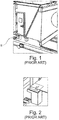
- plenum 100 is placed on a plurality of supports 110 provided on the baseplate B.
- Vertical alignment of the plenum 100 is achieved through a plurality of shims 120 respectively placed between a plenum base plate 105 and the supports 110.
- Lateral alignment is achieved through screws (not shown) operated for regulation from outside the plenum 100.
- the main disadvantages of the above solution derives from the fact that, in order to achieve the desired vertical alignment, shims 120 have to be positioned below the plenum 100 after the plenum 100 is placed on the supports 110. This results in complex and time-demanding alignment operation.
- alignment and checking operations must be performed separately, i.e. the alignment has to be checked after one or more of the shims 120 are placed. If the alignment is not acceptable, shims 120 have to be changed or modified. After such regulations, checking operations have to be performed again. Shims regulation and position checking have to be alternated till a satisfactory alignment result is achieved.
- US 2009/014621 A1 describes a mount assembly for securing a machine base to a foundation including: a first block secured to the machine base and a second block secured to the foundation.
- First and second blocks can be aligned horizontal with the use of bolts and vertically with the use of a flat shim plate.
- US 2005/086788 A1 describes a tooling system including a workstation assembly and a toolkit, is for performing an operation on a valve assembly.
- the present invention accomplish such an object by providing a turbomachine including a component fixedly constrainable to a baseplate of said turbomachine and an alignment device for regulating the position of said component with respect to the baseplate, wherein the alignment device includes at least a first bolt a second bolt and a third bolt, each bolt including a regulating screw respectively coupled with a threaded through hole in said component, each threaded hole defining a respective alignment axis for said component, each screw having a respective axial end which is susceptible of contacting said baseplate for defining the position of the component along each axis respectively, each bolt including a blocking nut for respectively blocking said regulating screws in said threaded holes; the alignment device further includes a fourth fixing screw which is screwable in a threaded hole of the baseplate (B) for fixing said component to the baseplate.
- One of the regulating screws of one of said bolts has a through hole coaxial with the respective alignment axis for housing said fourth fixing screw.
- the component of the turbomachine includes an inner cavity, said regulating screws of said bolts and said fixing screw being operatable from inside said inner cavity for respectively defining the position of the component and for fixing said component to the baseplate.
- the solution of the present invention allows to:
- the present invention provides an alignment device for regulating the position of a component of a turbomachine with respect to a baseplate of the turbomachine, wherein the alignment device includes at least a first bolt a second bolt and a third bolt, each bolt including a regulating screw respectively coupled with a threaded through hole in said component, each threaded hole defining a respective alignment axis for said component, each screw having a respective axial end which is susceptible of contacting said baseplate for defining the position of the component along each axis respectively, each bolt including a nut for respectively blocking said regulating screws in said threaded holes; the alignment device further includes a fourth fixing screw which is screwable in a threaded hole of the baseplate for fixing said component to the baseplate.
- One of the regulating screws of one of said bolts has a through hole coaxial with the respective alignment axis for housing said fourth fixing screw.
- the alignment device of the present invention allows to quickly and efficiently position components of a turbomachine with respect to the turbomachine baseplate, in order to correct align each component along the turbomachine rotation axis. Particularly, albeit not exclusively, such an alignment device is usable to align large and heavy components, like the inlet plenum in a gas turbine machine.
- the present invention provides a method for regulating the position of a component of a turbomachine with respect to a baseplate of the turbomachine, wherein the alignment method includes the steps of:
- One of the regulating screws of one of said bolts is provided with a through hole coaxial with the respective alignment axis for housing the fourth fixing screw, and the alignment method further including the step of inserting the fourth fixing screw in the through hole of the regulating screw before screwing the fourth fixing screw in the threaded hole of the baseplate (B).
- a first and a second embodiment of the present invention are shown in figures 3 to 6 .
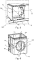
- a turbomachine 200 comprise a baseplate B and a plurality of components directly or indirectly fixable to the baseplate B in order to be correctly aligned along an axis of rotation W of the turbomachine 200.
- the turbomachine 200 is constituted by a gas turbine machine, whose components include an inlet plenum 100, a compressor 150, a combustor 160, a gas turbine 170 and an outlet plenum (not shown). Both the compressor 150 and the turbine 170 includes rotors which rotate around axis W.
- the present invention is also applicable to other types of turbomachine, whenever a component of the turbomachine 200 has to be fixedly constrained to the baseplate B by means of an alignment device 10 having the characteristics described in the following.
- the alignment device 10 is at least associated with the inlet plenum 100, for regulating the position of the inlet plenum 100 with respect to the baseplate B.
- the inlet plenum 100 comprises a rectangular base 111, a front wall 112 having a circular aperture 116, a rear wall 113 opposite to the front wall 112 and two lateral walls 114, 115, extending between the front and the rear walls 112, 113.
- the four walls 112, 113, 114, 115 are orthogonal to the base 111, each wall extending from a respective edge of the base 111.
- the volume comprised between the base 111 and the walls 112, 113, 114, 115 defines a parallelepiped-shaped cavity 101.
- the turbomachine 200 comprises four alignment devices 10 (only three alignment devices 10 are visible in figure 3 ) for regulating the position of the inlet plenum 100 with respect to the baseplate B, in such a way that the circular aperture 116 is aligned with the rotation axis W. This assures a correct coupling between the inlet plenum 100 and an inlet section 151 of the compressor 150.
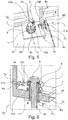
- Figures 5 and 6 show the corner between the base 111 and the front and lateral walls 112, 114 of the inlet plenum 100, including one of the four alignment devices 10 for aligning the plenum 100 with respect to the baseplate B.
- the description which follows will be referred to the alignment device of figures 5 and 6 .
- Each of the other three alignment devices 10 are identical to that of figures 5 and 6 , each being different from the others only for position and orientation.
- Each alignment device 10 includes a first bolt 3a, a second bolt 3b and a third bolt 1, each bolt 3a, 3b, 1 including a respective regulating screw 30a, 30b, 30c respectively coupled with a threaded through hole 7a, 7b, 7c provided in the inlet plenum 100 in the walls and in the base 111 of the inlet plenum 100.
- the threaded through hole 7a, 7b respectively coupled with the regulating screws 30a, 30b of the first and second bolt 3a, 3b are provided in the lateral wall 114 and in the rear wall 113, respectively.
- threaded through hole 7c coupled with the regulating screw 30c of the third bolt 1 is provided in the base 111.
- Each threaded through hole 7a, 7b, 7c defines a respective alignment axis X, Y, Z for the inlet plenum 100.
- the alignment axes X, Y, Z are mutually orthogonal, the axes X, Y of the first and second bolt 3a, 3b being oriented horizontally, i.e. parallel to the baseplate B, the axis Z of the third bolt 1 being oriented vertically, i.e. orthogonally to the baseplate B.
- the axis X of the first bolt is orthogonal to the rotation axis W and the axis Y is parallel to the rotation axis W.
- the regulating screws 30a, 30b, 30c are inserted in the respective threaded through hole 7a, 7b, 7c in such a way that each screw head is placed in the cavity 101.
- Each of the screws 30a, 30b, 30c can be therefore operated by an operator standing inside the inlet plenum 100, i.e. in the cavity 101.
- each screw 30a, 30b, 30c has a respective axial end 31a, 31b, 31c which is susceptible of protruding outside the inlet plenum 100 when each screw is coupled with the respective through hole 7a, 7b, 7c.
- Each axial end 31a, 31b, 31c contacts a respective surface B1, B2, B3, provided in the baseplate B and oriented orthogonally to the alignment axes X, Y, Z, respectively.
- the length of the portion of each screw 30a, 30b, 30c which protrudes outside the inlet plenum 100 defines the distance of the inlet plenum 100, along each alignment axis X, Y, Z, from the surfaces B1, B2, B3 of the baseplate B, respectively.
- Each bolt 3a, 3b, 1 includes a blocking nut 4a, 4b, 4c for respectively blocking each regulating screw 30a, 30b, 30c in the respective threaded hole 7a, 7b, 7c.
- Each blocking nut 4a, 4b, 4c is coupled with a respective portion of each regulating screw 30a, 30b, 30c immediately under the head thereof.
- each screw 30a, 30b, 30c is respectively coupled with the respective through hole 7a, 7b, 7c
- each nut 4a, 4b, 4c is operatable from inside the cavity 101 to be screwed against the wall 112, 113, 114, 115 or base 111 of the inlet plenum 100 which is provided with the threaded through hole 7a, 7b, 7c, respectively.
- an operator While standing inside the cavity 101, an operator can easily regulate the screws 30a, 30b, 30c, thus regulating the position of the inlet plenum 100 along each alignment axis X, Y, Z. From the same standing position, after checking the position of the inlet plenum 100, the operator can easily block each regulating screw 30a, 30b, 30c through the respective blocking nut 4a, 4b, 4c, thus defining the position of the inlet plenum 100 along each alignment axis X, Y, Z.
- the first and second bolt 3a, 3b are of the conventional type.
- the third bolt 1 comprises a longitudinal through hole 40 in the regulating screw 30c, which is coaxial with the respective alignment axis Z when the respective screw 30c is coupled with the respective through hole 7c.
- the hole 40 houses a fourth fixing screw 5 which is couplable with a threaded hole 50 provided in the surface B3 of the baseplate B for fixing the position of the inlet plenum 100 with respect to the baseplate B.
- the diameter of the through hole 40 is slightly greater than the diameter of the fourth fixing screw 5 (for example, the difference between the diameters of this hole and this screw is a value in the range of 10-20 mm), in order to allow sufficient lateral (i.e. X and Y) movement (e.g. +/- 5-10 mm) of the inlet plenum during alignment.
- the head of the fourth fixing screw 5 is operatable from inside the cavity 101.
- a washer 6 is provided between the head of the regulating screw 30c and the head of the fixing screw 5 in order to provide a convenient mating surface between the fourth fixing screw 5 and the third bolt 1.
- the operator While standing inside the cavity 101 and after block each regulating screw 30a, 30b, 30c through the respective blocking nut 4a, 4b, 4c, the operator can also fix the position of the inlet plenum 100 with respect to the base plate B, by screwing the fourth fixing screw 5 in the threaded hole 50.
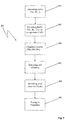
- an alignment method 300 for regulating the position of the inlet plenum 100 includes:
- one end of the shank of the screw 30c abuts on the surface B3 of the baseplate B; in this way, by screwing/unscrewing the screw 30c the position of the plenum 100 is regulated with respect to the baseplate B.
- the plenum 10 is fixed to the baseplate B by means of the screw 5 and the hole 50.
- the regulating screw e.g. screw 30c
- the fixing screw is external to the regulating screw; they are typically parallel to each other; the inlet plenum is provided with a non-threaded through hole for the fixing screw distinct from the through hole for the regulating screw; typically, they are close to each other and parallel to each other; the diameter of the fixing screw through hole is slightly greater than the diameter of the fixing screw (for example, the difference between the diameters of this hole and this screw is a value in the range of 10-20 mm), in order to allow sufficient lateral (i.e.
Landscapes
- Engineering & Computer Science (AREA)
- Mechanical Engineering (AREA)
- General Engineering & Computer Science (AREA)
- Structures Of Non-Positive Displacement Pumps (AREA)
- Connection Of Plates (AREA)
Claims (8)
- Ausrichtungsvorrichtung (10) zum Einstellen der Position einer Komponente (100) einer Turbomaschine (200) in Bezug auf eine Grundplatte (B) der Turbomaschine (200), wobei die Ausrichtungsvorrichtung (10) mindestens einen ersten Bolzen (3a), einen zweiten Bolzen (3b) und einen dritten Bolzen (1) einschließt, wobei jeder Bolzen (3a, 3b, 1) eine Stellschraube (30a, 30b, 30c) einschließt, die jeweils mit einem Gewindedurchgangsloch in der Komponente (100) gekoppelt ist, wobei jedes Gewindedurchgangsloch eine jeweilige Ausrichtungsachse (X, Y, Z) für die Komponente (100) definiert, wobei jede Schraube ein jeweiliges axiales Ende aufweist, das zum Kontaktieren der Grundplatte (B) zum Definieren der Position der Komponente (100) entlang jeder Achse (X, Y, Z) geeignet ist, wobei jeder Bolzen (3a, 3b, 1) eine Blockiermutter (4a, 4b, 4c) zum jeweiligen Blockieren der Stellschrauben in den Gewindelöchern einschließt;
wobei die Ausrichtungsvorrichtung (10) ferner eine vierte Befestigungsschraube (5) einschließt, die in ein Gewindeloch (50) der Grundplatte (B) zum Befestigen der Komponente (100) an der Grundplatte (B) geschraubt werden kann;
wobei eine der Stellschrauben (30c) eines der Bolzen (1) ein zur jeweiligen Ausrichtungsachse (Z) koaxiales Durchgangsloch (40) zum Aufnehmen der vierten Befestigungsschraube (5) aufweist. - Turbomaschine (200) einschließlich einer an einer Grundplatte (B) der Turbomaschine (200) fest beschränkbaren Komponente (100) und einer Ausrichtungsvorrichtung (10) nach Anspruch 1 zum Einstellen der Position der Komponente (100) in Bezug auf die Grundplatte (B).
- Turbomaschine (200) nach Anspruch 2, wobei der Durchmesser des Durchgangslochs (40) in der Stellschraube (30c) größer ist als der Durchmesser der vierten Befestigungsschraube (5), um die seitliche Ausrichtung zu ermöglichen.
- Turbomaschine (200) nach einem der Ansprüche 2 bis 3, wobei die Ausrichtungsachsen (X, Y, Z) zueinander orthogonal sind.
- Turbomaschine (200) nach einem der Ansprüche 2 bis 4, wobei die Komponente (100) einen inneren Hohlraum (101) einschließt, wobei die Stellschrauben (30a, 30b, 30c) der Bolzen (3a, 3b, 1) und die Fixierschraube (5) von innerhalb des inneren Hohlraums (101) bedienbar sind, um jeweils die Position der Komponente (100) zu definieren und die Komponente (100) an der Grundplatte (B) zu befestigen.
- Turbomaschine (200) nach einem der Ansprüche 2 bis 5, wobei die Turbomaschine (200) eine Gasturbine ist.
- Turbomaschine (200) nach einem der Ansprüche 2 bis 6, wobei die Komponente (100) eine Einlasskammer der Gasturbinen-Turbomaschine ist.
- Ausrichtungsverfahren (300) zum Einstellen der Position einer Komponente (100) einer Turbomaschine (200) in Bezug auf eine Grundplatte (B) der Turbomaschine (200), wobei das Ausrichtungsverfahren folgende Schritte einschließt:- Bereitstellen (310) von mindestens einem ersten Bolzen (3a), einem zweiten Bolzen (3b) und einem dritten Bolzen (1), wobei jeder Bolzen (3a, 3b, 1) eine Stellschraube (30a, 30b, 30c) und eine Blockiermutter (4a, 4b, 4c) sowie eine vierte Befestigungsschraube (5) einschließt,- Bereitstellen (320), in der Komponente (100), von mindestens einem ersten Gewindedurchgangsloch (7a), einem zweiten Gewindedurchgangsloch (7b) und einem dritten Gewindedurchgangsloch (7c), wobei jedes Gewindeloch (7a, 7b, 7c) eine jeweilige Ausrichtungsachse (X, Y, Z) für die Komponente (100) definiert, wobei jedes Gewindeloch (7a, 7b, 7c) den gleichen Durchmesser der ersten, zweiten bzw. dritten Bolzen (3a, 3b, 1) aufweist, sowie, in der Grundplatte (B), von einem Gewindeloch (50),- Koppeln (330) jeder Stellschraube (30a, 30b, 30c) des ersten, zweiten und dritten Bolzen (3a, 3b, 1) mit dem ersten, zweiten bzw. dritten Gewindedurchgangsloch (7a, 7b, 7c),- derartiges Verschrauben (340) der Stellschrauben (30a, 30b, 30c) in den Gewindedurchgangslöchern (7a, 7b, 7c), dass ein jeweiliges axiales Ende jeder Schraube (30a, 30b, 30c) mit der Grundplatte (B) in Kontakt kommt, um jeweils die Position der Komponente (100) entlang jeder Achse (X, Y, Z) zu definieren,- Blockieren (350) der Stellschrauben (30a, 30b, 30c) in den Gewindelöchern (7a, 7b, 7c) jeweils mit der Blockiermutter (4a, 4b, 4c),- Verschrauben (360) der vierten Befestigungsschraube (5) in dem Gewindeloch (50) der Grundplatte (B), wodurch die Komponente (100) an der Grundplatte (B) befestigt wird;wobei eine der Stellschrauben (30c) von einem der Bolzen (1) mit einem Durchgangsloch (40) koaxial zu der jeweiligen Ausrichtungsachse (Z) versehen ist, um die vierte Befestigungsschraube (5) aufzunehmen, wobei das Verfahren (300) ferner den Schritt des Einsetzens (360) der vierten Befestigungsschraube (5) in dem Durchgangsloch (40) der Stellschraube (30c) vor dem Verschrauben der vierten Befestigungsschraube (5) in dem Gewindeloch (50) der Grundplatte (B) einschließt.
Applications Claiming Priority (2)
| Application Number | Priority Date | Filing Date | Title |
|---|---|---|---|
| IT000042A ITCO20120042A1 (it) | 2012-09-11 | 2012-09-11 | Dispositivo di allineamento per un componente di turbomacchina e turbomacchina includente tale dispositivo |
| PCT/EP2013/068473 WO2014040920A1 (en) | 2012-09-11 | 2013-09-06 | An alignment device for a turbomachine component and turbomachine including such device |
Publications (2)
| Publication Number | Publication Date |
|---|---|
| EP2912283A1 EP2912283A1 (de) | 2015-09-02 |
| EP2912283B1 true EP2912283B1 (de) | 2019-08-07 |
Family
ID=47222206
Family Applications (1)
| Application Number | Title | Priority Date | Filing Date |
|---|---|---|---|
| EP13759506.2A Not-in-force EP2912283B1 (de) | 2012-09-11 | 2013-09-06 | Ausrichtungsvorrichtung für eine turbomaschine und turbomaschine mit solch einer vorrichtung |
Country Status (11)
| Country | Link |
|---|---|
| US (1) | US20150240664A1 (de) |
| EP (1) | EP2912283B1 (de) |
| JP (1) | JP2015533979A (de) |
| KR (1) | KR20150053763A (de) |
| CN (1) | CN104755708B (de) |
| AU (1) | AU2013314452A1 (de) |
| BR (1) | BR112015005325A2 (de) |
| CA (1) | CA2883892A1 (de) |
| IT (1) | ITCO20120042A1 (de) |
| RU (1) | RU2015107336A (de) |
| WO (1) | WO2014040920A1 (de) |
Family Cites Families (11)
| Publication number | Priority date | Publication date | Assignee | Title |
|---|---|---|---|---|
| US2940784A (en) * | 1956-06-06 | 1960-06-14 | William B Fell | Precision threaded adjustment |
| JPS63160699U (de) * | 1987-04-09 | 1988-10-20 | ||
| JP3078362U (ja) * | 2000-12-15 | 2001-07-10 | 株式会社アイ・メックス | 免震装置の架台取付け用x軸.y軸.z軸調整ボルトを保有する治具。 |
| US6884014B2 (en) * | 2001-04-23 | 2005-04-26 | The Gates Corporation | Tolerance compensating mounting device |
| JP2003347387A (ja) * | 2002-05-29 | 2003-12-05 | Shinko Electric Co Ltd | 取付位置調整装置及び取付位置調整方法 |
| US7222417B2 (en) * | 2003-10-23 | 2007-05-29 | Siemens Power Generation, Inc. | Valve tooling system |
| US7588386B2 (en) * | 2006-08-30 | 2009-09-15 | Silicon Valley Automation | Leveling and aligning device |
| US7938379B2 (en) * | 2007-07-11 | 2011-05-10 | General Electric Company | Three axis adjustable mounting system |
| US8337151B2 (en) * | 2009-06-30 | 2012-12-25 | General Electric Company | System and method for aligning turbine components |
| US8528181B2 (en) * | 2009-07-10 | 2013-09-10 | Alstom Technology Ltd | Alignment of machine components within casings |
| KR101182331B1 (ko) * | 2010-12-21 | 2012-09-20 | 두산중공업 주식회사 | 가스터빈 엔진의 스키드 조절장치 |
-
2012
- 2012-09-11 IT IT000042A patent/ITCO20120042A1/it unknown
-
2013
- 2013-09-06 KR KR1020157006240A patent/KR20150053763A/ko not_active Withdrawn
- 2013-09-06 US US14/427,449 patent/US20150240664A1/en not_active Abandoned
- 2013-09-06 CA CA2883892A patent/CA2883892A1/en not_active Abandoned
- 2013-09-06 CN CN201380047307.0A patent/CN104755708B/zh not_active Expired - Fee Related
- 2013-09-06 EP EP13759506.2A patent/EP2912283B1/de not_active Not-in-force
- 2013-09-06 BR BR112015005325A patent/BR112015005325A2/pt not_active IP Right Cessation
- 2013-09-06 JP JP2015530411A patent/JP2015533979A/ja active Pending
- 2013-09-06 AU AU2013314452A patent/AU2013314452A1/en not_active Abandoned
- 2013-09-06 RU RU2015107336A patent/RU2015107336A/ru not_active Application Discontinuation
- 2013-09-06 WO PCT/EP2013/068473 patent/WO2014040920A1/en not_active Ceased
Non-Patent Citations (1)
| Title |
|---|
| None * |
Also Published As
| Publication number | Publication date |
|---|---|
| ITCO20120042A1 (it) | 2014-03-12 |
| US20150240664A1 (en) | 2015-08-27 |
| AU2013314452A1 (en) | 2015-03-26 |
| CN104755708A (zh) | 2015-07-01 |
| JP2015533979A (ja) | 2015-11-26 |
| CA2883892A1 (en) | 2014-03-20 |
| BR112015005325A2 (pt) | 2017-07-04 |
| EP2912283A1 (de) | 2015-09-02 |
| KR20150053763A (ko) | 2015-05-18 |
| CN104755708B (zh) | 2016-12-21 |
| WO2014040920A1 (en) | 2014-03-20 |
| RU2015107336A (ru) | 2016-11-10 |
Similar Documents
| Publication | Publication Date | Title |
|---|---|---|
| KR20170075007A (ko) | 부품 가공 지원 시스템 및 방법 | |
| KR101127036B1 (ko) | 가스터빈엔진의 고정장치 | |
| CN105793523A (zh) | 平衡式涡轮发动机部分以及涡轮发动机 | |
| US20150240664A1 (en) | Alignment device for a turbomachine component and turbomachine including such a device | |
| KR20130066252A (ko) | 가스터빈엔진의 위치조정 고정장치 | |
| KR101415495B1 (ko) | 설비 설치용 가이드 볼트 및 설비 설치용 가이드 볼트를 이용한 설비 설치 방법 | |
| KR102513002B1 (ko) | 편심크랭크샤프트의 위상고정장치 | |
| KR101580577B1 (ko) | 커플링 축 정렬용 측정 장치 | |
| US10109924B2 (en) | Method for assembling a multi-element apparatus using a reconfigurable assembly apparatus | |
| CN105716968B (zh) | 一种圆棒试样剪切装置 | |
| US20140312199A1 (en) | Adjustable gib shim | |
| EP2554308B1 (de) | Schablone und Verfahren zur Modifizierung eines Gehäuses in einem Turbinesystem | |
| CN209117291U (zh) | 一种服务器的固定装置 | |
| CN207351926U (zh) | 探测装置及扫描成像设备 | |
| US11385253B2 (en) | Triaxial accelerometer mounting adapter | |
| CN115329506B (zh) | 用于自由射流试验的动力装置安装架的设计方法及安装架 | |
| JP2026510175A (ja) | タービンアセンブリの交換部品を保護するための装置および方法 | |
| KR20140033963A (ko) | 브로치 머신의 센터링을 위한 센터링게이지 지그 및 이를 이용한 브로치 머신 센터링 방법 | |
| KR20150142431A (ko) | 균형 조절나사 | |
| CN103163982B (zh) | 风扇模组辅助固定装置 | |
| CN117754283A (zh) | 一种三自惯组的锁紧限位装置及其装配方法 | |
| CN117554053A (zh) | 转子试验支座及试验方法 | |
| CN107807138A (zh) | 探测装置及扫描成像设备 | |
| CN106112599A (zh) | 一种可精确垂直安装的工装夹具 | |
| WO2025109698A1 (ja) | 付加軸取付構造 |
Legal Events
| Date | Code | Title | Description |
|---|---|---|---|
| PUAI | Public reference made under article 153(3) epc to a published international application that has entered the european phase |
Free format text: ORIGINAL CODE: 0009012 |
|
| 17P | Request for examination filed |
Effective date: 20150413 |
|
| AK | Designated contracting states |
Kind code of ref document: A1 Designated state(s): AL AT BE BG CH CY CZ DE DK EE ES FI FR GB GR HR HU IE IS IT LI LT LU LV MC MK MT NL NO PL PT RO RS SE SI SK SM TR |
|
| AX | Request for extension of the european patent |
Extension state: BA ME |
|
| DAX | Request for extension of the european patent (deleted) | ||
| STAA | Information on the status of an ep patent application or granted ep patent |
Free format text: STATUS: EXAMINATION IS IN PROGRESS |
|
| 17Q | First examination report despatched |
Effective date: 20180516 |
|
| REG | Reference to a national code |
Ref country code: DE Ref legal event code: R079 Ref document number: 602013058819 Country of ref document: DE Free format text: PREVIOUS MAIN CLASS: F01D0025280000 Ipc: B23P0019100000 |
|
| GRAP | Despatch of communication of intention to grant a patent |
Free format text: ORIGINAL CODE: EPIDOSNIGR1 |
|
| STAA | Information on the status of an ep patent application or granted ep patent |
Free format text: STATUS: GRANT OF PATENT IS INTENDED |
|
| RIC1 | Information provided on ipc code assigned before grant |
Ipc: B23P 19/10 20060101AFI20181122BHEP Ipc: F01D 25/24 20060101ALI20181122BHEP Ipc: F01D 25/28 20060101ALI20181122BHEP |
|
| INTG | Intention to grant announced |
Effective date: 20181221 |
|
| GRAS | Grant fee paid |
Free format text: ORIGINAL CODE: EPIDOSNIGR3 |
|
| GRAA | (expected) grant |
Free format text: ORIGINAL CODE: 0009210 |
|
| STAA | Information on the status of an ep patent application or granted ep patent |
Free format text: STATUS: THE PATENT HAS BEEN GRANTED |
|
| AK | Designated contracting states |
Kind code of ref document: B1 Designated state(s): AL AT BE BG CH CY CZ DE DK EE ES FI FR GB GR HR HU IE IS IT LI LT LU LV MC MK MT NL NO PL PT RO RS SE SI SK SM TR |
|
| REG | Reference to a national code |
Ref country code: GB Ref legal event code: FG4D |
|
| REG | Reference to a national code |
Ref country code: CH Ref legal event code: EP Ref country code: AT Ref legal event code: REF Ref document number: 1163096 Country of ref document: AT Kind code of ref document: T Effective date: 20190815 |
|
| REG | Reference to a national code |
Ref country code: DE Ref legal event code: R096 Ref document number: 602013058819 Country of ref document: DE |
|
| REG | Reference to a national code |
Ref country code: IE Ref legal event code: FG4D |
|
| REG | Reference to a national code |
Ref country code: NL Ref legal event code: MP Effective date: 20190807 |
|
| REG | Reference to a national code |
Ref country code: LT Ref legal event code: MG4D |
|
| PGFP | Annual fee paid to national office [announced via postgrant information from national office to epo] |
Ref country code: AT Payment date: 20190920 Year of fee payment: 7 |
|
| PG25 | Lapsed in a contracting state [announced via postgrant information from national office to epo] |
Ref country code: BG Free format text: LAPSE BECAUSE OF FAILURE TO SUBMIT A TRANSLATION OF THE DESCRIPTION OR TO PAY THE FEE WITHIN THE PRESCRIBED TIME-LIMIT Effective date: 20191107 Ref country code: SE Free format text: LAPSE BECAUSE OF FAILURE TO SUBMIT A TRANSLATION OF THE DESCRIPTION OR TO PAY THE FEE WITHIN THE PRESCRIBED TIME-LIMIT Effective date: 20190807 Ref country code: NL Free format text: LAPSE BECAUSE OF FAILURE TO SUBMIT A TRANSLATION OF THE DESCRIPTION OR TO PAY THE FEE WITHIN THE PRESCRIBED TIME-LIMIT Effective date: 20190807 Ref country code: HR Free format text: LAPSE BECAUSE OF FAILURE TO SUBMIT A TRANSLATION OF THE DESCRIPTION OR TO PAY THE FEE WITHIN THE PRESCRIBED TIME-LIMIT Effective date: 20190807 Ref country code: PT Free format text: LAPSE BECAUSE OF FAILURE TO SUBMIT A TRANSLATION OF THE DESCRIPTION OR TO PAY THE FEE WITHIN THE PRESCRIBED TIME-LIMIT Effective date: 20191209 Ref country code: FI Free format text: LAPSE BECAUSE OF FAILURE TO SUBMIT A TRANSLATION OF THE DESCRIPTION OR TO PAY THE FEE WITHIN THE PRESCRIBED TIME-LIMIT Effective date: 20190807 Ref country code: LT Free format text: LAPSE BECAUSE OF FAILURE TO SUBMIT A TRANSLATION OF THE DESCRIPTION OR TO PAY THE FEE WITHIN THE PRESCRIBED TIME-LIMIT Effective date: 20190807 Ref country code: NO Free format text: LAPSE BECAUSE OF FAILURE TO SUBMIT A TRANSLATION OF THE DESCRIPTION OR TO PAY THE FEE WITHIN THE PRESCRIBED TIME-LIMIT Effective date: 20191107 |
|
| REG | Reference to a national code |
Ref country code: AT Ref legal event code: MK05 Ref document number: 1163096 Country of ref document: AT Kind code of ref document: T Effective date: 20190807 |
|
| PG25 | Lapsed in a contracting state [announced via postgrant information from national office to epo] |
Ref country code: AL Free format text: LAPSE BECAUSE OF FAILURE TO SUBMIT A TRANSLATION OF THE DESCRIPTION OR TO PAY THE FEE WITHIN THE PRESCRIBED TIME-LIMIT Effective date: 20190807 Ref country code: ES Free format text: LAPSE BECAUSE OF FAILURE TO SUBMIT A TRANSLATION OF THE DESCRIPTION OR TO PAY THE FEE WITHIN THE PRESCRIBED TIME-LIMIT Effective date: 20190807 Ref country code: IS Free format text: LAPSE BECAUSE OF FAILURE TO SUBMIT A TRANSLATION OF THE DESCRIPTION OR TO PAY THE FEE WITHIN THE PRESCRIBED TIME-LIMIT Effective date: 20191207 Ref country code: LV Free format text: LAPSE BECAUSE OF FAILURE TO SUBMIT A TRANSLATION OF THE DESCRIPTION OR TO PAY THE FEE WITHIN THE PRESCRIBED TIME-LIMIT Effective date: 20190807 Ref country code: GR Free format text: LAPSE BECAUSE OF FAILURE TO SUBMIT A TRANSLATION OF THE DESCRIPTION OR TO PAY THE FEE WITHIN THE PRESCRIBED TIME-LIMIT Effective date: 20191108 Ref country code: RS Free format text: LAPSE BECAUSE OF FAILURE TO SUBMIT A TRANSLATION OF THE DESCRIPTION OR TO PAY THE FEE WITHIN THE PRESCRIBED TIME-LIMIT Effective date: 20190807 |
|
| PGFP | Annual fee paid to national office [announced via postgrant information from national office to epo] |
Ref country code: ES Payment date: 20191104 Year of fee payment: 7 |
|
| PG25 | Lapsed in a contracting state [announced via postgrant information from national office to epo] |
Ref country code: TR Free format text: LAPSE BECAUSE OF FAILURE TO SUBMIT A TRANSLATION OF THE DESCRIPTION OR TO PAY THE FEE WITHIN THE PRESCRIBED TIME-LIMIT Effective date: 20190807 |
|
| PG25 | Lapsed in a contracting state [announced via postgrant information from national office to epo] |
Ref country code: IT Free format text: LAPSE BECAUSE OF FAILURE TO SUBMIT A TRANSLATION OF THE DESCRIPTION OR TO PAY THE FEE WITHIN THE PRESCRIBED TIME-LIMIT Effective date: 20190807 Ref country code: RO Free format text: LAPSE BECAUSE OF FAILURE TO SUBMIT A TRANSLATION OF THE DESCRIPTION OR TO PAY THE FEE WITHIN THE PRESCRIBED TIME-LIMIT Effective date: 20190807 Ref country code: EE Free format text: LAPSE BECAUSE OF FAILURE TO SUBMIT A TRANSLATION OF THE DESCRIPTION OR TO PAY THE FEE WITHIN THE PRESCRIBED TIME-LIMIT Effective date: 20190807 Ref country code: PL Free format text: LAPSE BECAUSE OF FAILURE TO SUBMIT A TRANSLATION OF THE DESCRIPTION OR TO PAY THE FEE WITHIN THE PRESCRIBED TIME-LIMIT Effective date: 20190807 Ref country code: DK Free format text: LAPSE BECAUSE OF FAILURE TO SUBMIT A TRANSLATION OF THE DESCRIPTION OR TO PAY THE FEE WITHIN THE PRESCRIBED TIME-LIMIT Effective date: 20190807 Ref country code: AT Free format text: LAPSE BECAUSE OF FAILURE TO SUBMIT A TRANSLATION OF THE DESCRIPTION OR TO PAY THE FEE WITHIN THE PRESCRIBED TIME-LIMIT Effective date: 20190807 |
|
| PG25 | Lapsed in a contracting state [announced via postgrant information from national office to epo] |
Ref country code: MC Free format text: LAPSE BECAUSE OF FAILURE TO SUBMIT A TRANSLATION OF THE DESCRIPTION OR TO PAY THE FEE WITHIN THE PRESCRIBED TIME-LIMIT Effective date: 20190807 Ref country code: SK Free format text: LAPSE BECAUSE OF FAILURE TO SUBMIT A TRANSLATION OF THE DESCRIPTION OR TO PAY THE FEE WITHIN THE PRESCRIBED TIME-LIMIT Effective date: 20190807 Ref country code: IS Free format text: LAPSE BECAUSE OF FAILURE TO SUBMIT A TRANSLATION OF THE DESCRIPTION OR TO PAY THE FEE WITHIN THE PRESCRIBED TIME-LIMIT Effective date: 20200224 Ref country code: SM Free format text: LAPSE BECAUSE OF FAILURE TO SUBMIT A TRANSLATION OF THE DESCRIPTION OR TO PAY THE FEE WITHIN THE PRESCRIBED TIME-LIMIT Effective date: 20190807 Ref country code: CZ Free format text: LAPSE BECAUSE OF FAILURE TO SUBMIT A TRANSLATION OF THE DESCRIPTION OR TO PAY THE FEE WITHIN THE PRESCRIBED TIME-LIMIT Effective date: 20190807 |
|
| REG | Reference to a national code |
Ref country code: CH Ref legal event code: PL |
|
| REG | Reference to a national code |
Ref country code: DE Ref legal event code: R097 Ref document number: 602013058819 Country of ref document: DE |
|
| PLBE | No opposition filed within time limit |
Free format text: ORIGINAL CODE: 0009261 |
|
| STAA | Information on the status of an ep patent application or granted ep patent |
Free format text: STATUS: NO OPPOSITION FILED WITHIN TIME LIMIT |
|
| PG2D | Information on lapse in contracting state deleted |
Ref country code: IS |
|
| PG25 | Lapsed in a contracting state [announced via postgrant information from national office to epo] |
Ref country code: LI Free format text: LAPSE BECAUSE OF NON-PAYMENT OF DUE FEES Effective date: 20190930 Ref country code: CH Free format text: LAPSE BECAUSE OF NON-PAYMENT OF DUE FEES Effective date: 20190930 Ref country code: IE Free format text: LAPSE BECAUSE OF NON-PAYMENT OF DUE FEES Effective date: 20190906 Ref country code: LU Free format text: LAPSE BECAUSE OF NON-PAYMENT OF DUE FEES Effective date: 20190906 |
|
| REG | Reference to a national code |
Ref country code: BE Ref legal event code: MM Effective date: 20190930 |
|
| 26N | No opposition filed |
Effective date: 20200603 |
|
| PG25 | Lapsed in a contracting state [announced via postgrant information from national office to epo] |
Ref country code: BE Free format text: LAPSE BECAUSE OF NON-PAYMENT OF DUE FEES Effective date: 20190930 Ref country code: SI Free format text: LAPSE BECAUSE OF FAILURE TO SUBMIT A TRANSLATION OF THE DESCRIPTION OR TO PAY THE FEE WITHIN THE PRESCRIBED TIME-LIMIT Effective date: 20190807 |
|
| PG25 | Lapsed in a contracting state [announced via postgrant information from national office to epo] |
Ref country code: FR Free format text: LAPSE BECAUSE OF NON-PAYMENT OF DUE FEES Effective date: 20191007 |
|
| PGFP | Annual fee paid to national office [announced via postgrant information from national office to epo] |
Ref country code: GB Payment date: 20200819 Year of fee payment: 8 Ref country code: DE Payment date: 20200819 Year of fee payment: 8 |
|
| PG25 | Lapsed in a contracting state [announced via postgrant information from national office to epo] |
Ref country code: CY Free format text: LAPSE BECAUSE OF FAILURE TO SUBMIT A TRANSLATION OF THE DESCRIPTION OR TO PAY THE FEE WITHIN THE PRESCRIBED TIME-LIMIT Effective date: 20190807 |
|
| PG25 | Lapsed in a contracting state [announced via postgrant information from national office to epo] |
Ref country code: MT Free format text: LAPSE BECAUSE OF FAILURE TO SUBMIT A TRANSLATION OF THE DESCRIPTION OR TO PAY THE FEE WITHIN THE PRESCRIBED TIME-LIMIT Effective date: 20190807 Ref country code: HU Free format text: LAPSE BECAUSE OF FAILURE TO SUBMIT A TRANSLATION OF THE DESCRIPTION OR TO PAY THE FEE WITHIN THE PRESCRIBED TIME-LIMIT; INVALID AB INITIO Effective date: 20130906 |
|
| REG | Reference to a national code |
Ref country code: DE Ref legal event code: R119 Ref document number: 602013058819 Country of ref document: DE |
|
| GBPC | Gb: european patent ceased through non-payment of renewal fee |
Effective date: 20210906 |
|
| PG25 | Lapsed in a contracting state [announced via postgrant information from national office to epo] |
Ref country code: MK Free format text: LAPSE BECAUSE OF FAILURE TO SUBMIT A TRANSLATION OF THE DESCRIPTION OR TO PAY THE FEE WITHIN THE PRESCRIBED TIME-LIMIT Effective date: 20190807 |
|
| PG25 | Lapsed in a contracting state [announced via postgrant information from national office to epo] |
Ref country code: GB Free format text: LAPSE BECAUSE OF NON-PAYMENT OF DUE FEES Effective date: 20210906 Ref country code: DE Free format text: LAPSE BECAUSE OF NON-PAYMENT OF DUE FEES Effective date: 20220401 |