EP2911839B1 - Method and apparatus for positioning a cutting apparatus - Google Patents
Method and apparatus for positioning a cutting apparatus Download PDFInfo
- Publication number
- EP2911839B1 EP2911839B1 EP13786076.3A EP13786076A EP2911839B1 EP 2911839 B1 EP2911839 B1 EP 2911839B1 EP 13786076 A EP13786076 A EP 13786076A EP 2911839 B1 EP2911839 B1 EP 2911839B1
- Authority
- EP
- European Patent Office
- Prior art keywords
- frame
- roll
- cutting
- stationary member
- longitudinal axis
- Prior art date
- Legal status (The legal status is an assumption and is not a legal conclusion. Google has not performed a legal analysis and makes no representation as to the accuracy of the status listed.)
- Active
Links
- 238000005520 cutting process Methods 0.000 title claims description 215
- 238000000034 method Methods 0.000 title claims description 37
- 238000012546 transfer Methods 0.000 claims description 50
- 239000000758 substrate Substances 0.000 claims description 30
- 230000002950 deficient Effects 0.000 claims description 13
- 230000000712 assembly Effects 0.000 description 48
- 238000000429 assembly Methods 0.000 description 48
- 230000002745 absorbent Effects 0.000 description 38
- 239000002250 absorbent Substances 0.000 description 38
- 239000000463 material Substances 0.000 description 31
- 239000000306 component Substances 0.000 description 22
- 238000005304 joining Methods 0.000 description 9
- 238000004519 manufacturing process Methods 0.000 description 9
- 230000008569 process Effects 0.000 description 8
- 239000013013 elastic material Substances 0.000 description 7
- 239000004745 nonwoven fabric Substances 0.000 description 7
- 239000000853 adhesive Substances 0.000 description 5
- 230000001070 adhesive effect Effects 0.000 description 5
- 238000011144 upstream manufacturing Methods 0.000 description 5
- 230000004888 barrier function Effects 0.000 description 4
- 239000010408 film Substances 0.000 description 4
- 239000012209 synthetic fiber Substances 0.000 description 3
- 229920002994 synthetic fiber Polymers 0.000 description 3
- 206010021639 Incontinence Diseases 0.000 description 2
- 229910001315 Tool steel Inorganic materials 0.000 description 2
- 239000011888 foil Substances 0.000 description 2
- 230000002209 hydrophobic effect Effects 0.000 description 2
- 239000010410 layer Substances 0.000 description 2
- 239000002985 plastic film Substances 0.000 description 2
- 229920006255 plastic film Polymers 0.000 description 2
- -1 polyethylene Polymers 0.000 description 2
- UONOETXJSWQNOL-UHFFFAOYSA-N tungsten carbide Chemical compound [W+]#[C-] UONOETXJSWQNOL-UHFFFAOYSA-N 0.000 description 2
- 229920000742 Cotton Polymers 0.000 description 1
- JOYRKODLDBILNP-UHFFFAOYSA-N Ethyl urethane Chemical compound CCOC(N)=O JOYRKODLDBILNP-UHFFFAOYSA-N 0.000 description 1
- 244000261422 Lysimachia clethroides Species 0.000 description 1
- 239000004952 Polyamide Substances 0.000 description 1
- 239000004698 Polyethylene Substances 0.000 description 1
- 239000004743 Polypropylene Substances 0.000 description 1
- 229910000831 Steel Inorganic materials 0.000 description 1
- 229920002522 Wood fibre Polymers 0.000 description 1
- 238000013459 approach Methods 0.000 description 1
- 230000009286 beneficial effect Effects 0.000 description 1
- 230000006835 compression Effects 0.000 description 1
- 238000007906 compression Methods 0.000 description 1
- 230000008602 contraction Effects 0.000 description 1
- 239000008358 core component Substances 0.000 description 1
- 230000008878 coupling Effects 0.000 description 1
- 238000010168 coupling process Methods 0.000 description 1
- 238000005859 coupling reaction Methods 0.000 description 1
- 230000001419 dependent effect Effects 0.000 description 1
- 210000005069 ears Anatomy 0.000 description 1
- 210000000416 exudates and transudate Anatomy 0.000 description 1
- 239000000835 fiber Substances 0.000 description 1
- 239000002657 fibrous material Substances 0.000 description 1
- 238000013023 gasketing Methods 0.000 description 1
- 230000002452 interceptive effect Effects 0.000 description 1
- 238000012423 maintenance Methods 0.000 description 1
- 230000007246 mechanism Effects 0.000 description 1
- 238000012986 modification Methods 0.000 description 1
- 230000004048 modification Effects 0.000 description 1
- 239000002245 particle Substances 0.000 description 1
- 229920002647 polyamide Polymers 0.000 description 1
- 229920000728 polyester Polymers 0.000 description 1
- 229920000573 polyethylene Polymers 0.000 description 1
- 229920000098 polyolefin Polymers 0.000 description 1
- 229920001155 polypropylene Polymers 0.000 description 1
- 229920001296 polysiloxane Polymers 0.000 description 1
- 230000004044 response Effects 0.000 description 1
- 239000005060 rubber Substances 0.000 description 1
- 239000002689 soil Substances 0.000 description 1
- 239000010959 steel Substances 0.000 description 1
- 238000012360 testing method Methods 0.000 description 1
- 238000012549 training Methods 0.000 description 1
- 239000002023 wood Substances 0.000 description 1
Images


Classifications
-
- B—PERFORMING OPERATIONS; TRANSPORTING
- B26—HAND CUTTING TOOLS; CUTTING; SEVERING
- B26D—CUTTING; DETAILS COMMON TO MACHINES FOR PERFORATING, PUNCHING, CUTTING-OUT, STAMPING-OUT OR SEVERING
- B26D1/00—Cutting through work characterised by the nature or movement of the cutting member or particular materials not otherwise provided for; Apparatus or machines therefor; Cutting members therefor
- B26D1/01—Cutting through work characterised by the nature or movement of the cutting member or particular materials not otherwise provided for; Apparatus or machines therefor; Cutting members therefor involving a cutting member which does not travel with the work
- B26D1/12—Cutting through work characterised by the nature or movement of the cutting member or particular materials not otherwise provided for; Apparatus or machines therefor; Cutting members therefor involving a cutting member which does not travel with the work having a cutting member moving about an axis
- B26D1/25—Cutting through work characterised by the nature or movement of the cutting member or particular materials not otherwise provided for; Apparatus or machines therefor; Cutting members therefor involving a cutting member which does not travel with the work having a cutting member moving about an axis with a non-circular cutting member
- B26D1/34—Cutting through work characterised by the nature or movement of the cutting member or particular materials not otherwise provided for; Apparatus or machines therefor; Cutting members therefor involving a cutting member which does not travel with the work having a cutting member moving about an axis with a non-circular cutting member moving about an axis parallel to the line of cut
- B26D1/40—Cutting through work characterised by the nature or movement of the cutting member or particular materials not otherwise provided for; Apparatus or machines therefor; Cutting members therefor involving a cutting member which does not travel with the work having a cutting member moving about an axis with a non-circular cutting member moving about an axis parallel to the line of cut and coacting with a rotary member
- B26D1/405—Cutting through work characterised by the nature or movement of the cutting member or particular materials not otherwise provided for; Apparatus or machines therefor; Cutting members therefor involving a cutting member which does not travel with the work having a cutting member moving about an axis with a non-circular cutting member moving about an axis parallel to the line of cut and coacting with a rotary member for thin material, e.g. for sheets, strips or the like
-
- A—HUMAN NECESSITIES
- A61—MEDICAL OR VETERINARY SCIENCE; HYGIENE
- A61F—FILTERS IMPLANTABLE INTO BLOOD VESSELS; PROSTHESES; DEVICES PROVIDING PATENCY TO, OR PREVENTING COLLAPSING OF, TUBULAR STRUCTURES OF THE BODY, e.g. STENTS; ORTHOPAEDIC, NURSING OR CONTRACEPTIVE DEVICES; FOMENTATION; TREATMENT OR PROTECTION OF EYES OR EARS; BANDAGES, DRESSINGS OR ABSORBENT PADS; FIRST-AID KITS
- A61F13/00—Bandages or dressings; Absorbent pads
- A61F13/15—Absorbent pads, e.g. sanitary towels, swabs or tampons for external or internal application to the body; Supporting or fastening means therefor; Tampon applicators
- A61F13/15577—Apparatus or processes for manufacturing
- A61F13/15707—Mechanical treatment, e.g. notching, twisting, compressing, shaping
- A61F13/15723—Partitioning batts; Cutting
-
- B—PERFORMING OPERATIONS; TRANSPORTING
- B26—HAND CUTTING TOOLS; CUTTING; SEVERING
- B26D—CUTTING; DETAILS COMMON TO MACHINES FOR PERFORATING, PUNCHING, CUTTING-OUT, STAMPING-OUT OR SEVERING
- B26D5/00—Arrangements for operating and controlling machines or devices for cutting, cutting-out, stamping-out, punching, perforating, or severing by means other than cutting
-
- B—PERFORMING OPERATIONS; TRANSPORTING
- B26—HAND CUTTING TOOLS; CUTTING; SEVERING
- B26D—CUTTING; DETAILS COMMON TO MACHINES FOR PERFORATING, PUNCHING, CUTTING-OUT, STAMPING-OUT OR SEVERING
- B26D7/00—Details of apparatus for cutting, cutting-out, stamping-out, punching, perforating, or severing by means other than cutting
- B26D7/26—Means for mounting or adjusting the cutting member; Means for adjusting the stroke of the cutting member
- B26D7/2628—Means for adjusting the position of the cutting member
-
- B—PERFORMING OPERATIONS; TRANSPORTING
- B26—HAND CUTTING TOOLS; CUTTING; SEVERING
- B26D—CUTTING; DETAILS COMMON TO MACHINES FOR PERFORATING, PUNCHING, CUTTING-OUT, STAMPING-OUT OR SEVERING
- B26D7/00—Details of apparatus for cutting, cutting-out, stamping-out, punching, perforating, or severing by means other than cutting
- B26D7/27—Means for performing other operations combined with cutting
- B26D7/32—Means for performing other operations combined with cutting for conveying or stacking cut product
-
- B—PERFORMING OPERATIONS; TRANSPORTING
- B26—HAND CUTTING TOOLS; CUTTING; SEVERING
- B26D—CUTTING; DETAILS COMMON TO MACHINES FOR PERFORATING, PUNCHING, CUTTING-OUT, STAMPING-OUT OR SEVERING
- B26D7/00—Details of apparatus for cutting, cutting-out, stamping-out, punching, perforating, or severing by means other than cutting
- B26D7/26—Means for mounting or adjusting the cutting member; Means for adjusting the stroke of the cutting member
- B26D7/2628—Means for adjusting the position of the cutting member
- B26D7/265—Journals, bearings or supports for positioning rollers or cylinders relatively to each other
-
- B—PERFORMING OPERATIONS; TRANSPORTING
- B26—HAND CUTTING TOOLS; CUTTING; SEVERING
- B26F—PERFORATING; PUNCHING; CUTTING-OUT; STAMPING-OUT; SEVERING BY MEANS OTHER THAN CUTTING
- B26F1/00—Perforating; Punching; Cutting-out; Stamping-out; Apparatus therefor
- B26F1/38—Cutting-out; Stamping-out
- B26F1/384—Cutting-out; Stamping-out using rotating drums
-
- Y—GENERAL TAGGING OF NEW TECHNOLOGICAL DEVELOPMENTS; GENERAL TAGGING OF CROSS-SECTIONAL TECHNOLOGIES SPANNING OVER SEVERAL SECTIONS OF THE IPC; TECHNICAL SUBJECTS COVERED BY FORMER USPC CROSS-REFERENCE ART COLLECTIONS [XRACs] AND DIGESTS
- Y10—TECHNICAL SUBJECTS COVERED BY FORMER USPC
- Y10T—TECHNICAL SUBJECTS COVERED BY FORMER US CLASSIFICATION
- Y10T29/00—Metal working
- Y10T29/49—Method of mechanical manufacture
- Y10T29/49764—Method of mechanical manufacture with testing or indicating
- Y10T29/49778—Method of mechanical manufacture with testing or indicating with aligning, guiding, or instruction
-
- Y—GENERAL TAGGING OF NEW TECHNOLOGICAL DEVELOPMENTS; GENERAL TAGGING OF CROSS-SECTIONAL TECHNOLOGIES SPANNING OVER SEVERAL SECTIONS OF THE IPC; TECHNICAL SUBJECTS COVERED BY FORMER USPC CROSS-REFERENCE ART COLLECTIONS [XRACs] AND DIGESTS
- Y10—TECHNICAL SUBJECTS COVERED BY FORMER USPC
- Y10T—TECHNICAL SUBJECTS COVERED BY FORMER US CLASSIFICATION
- Y10T83/00—Cutting
- Y10T83/04—Processes
- Y10T83/0448—With subsequent handling [i.e., of product]
- Y10T83/0467—By separating products from each other
-
- Y—GENERAL TAGGING OF NEW TECHNOLOGICAL DEVELOPMENTS; GENERAL TAGGING OF CROSS-SECTIONAL TECHNOLOGIES SPANNING OVER SEVERAL SECTIONS OF THE IPC; TECHNICAL SUBJECTS COVERED BY FORMER USPC CROSS-REFERENCE ART COLLECTIONS [XRACs] AND DIGESTS
- Y10—TECHNICAL SUBJECTS COVERED BY FORMER USPC
- Y10T—TECHNICAL SUBJECTS COVERED BY FORMER US CLASSIFICATION
- Y10T83/00—Cutting
- Y10T83/465—Cutting motion of tool has component in direction of moving work
- Y10T83/4766—Orbital motion of cutting blade
- Y10T83/4795—Rotary tool
- Y10T83/483—With cooperating rotary cutter or backup
- Y10T83/4838—With anvil backup
Description
- The present disclosure relates to methods and apparatuses for manufacturing absorbent articles, and more particularly, to methods and apparatuses for positioning a cutting apparatus during the manufacture of absorbent articles.
- Along an assembly line, various types of articles, such as diapers and other absorbent articles, may be assembled by adding components to and/or otherwise modifying an advancing, continuous web of material. For example, in some processes, advancing webs of material are combined with other advancing webs of material. In other examples, individual components created from advancing webs of material are combined with advancing webs of material, which in turn, are then combined with other advancing webs of material. In some cases, individual components created from advancing webs are combined with other individual components created from other advancing webs. Webs of material and component parts used to manufacture diapers may include: backsheets, topsheets, leg cuffs, waist bands, absorbent core components, front and/or back ears, fastening components, and various types of elastic webs and components such as leg elastics, barrier leg cuff elastics, stretch side panels, and waist elastics. Once the desired component parts are assembled, the advancing webs and component parts are subjected to a final cut to separate the webs into discrete diapers or other absorbent articles. The cut is performed between a cutting roll and an anvil roll, both rotatably mounted on a frame
- In some processes, a continuous length of diaper chassis advancing in a machine direction is cut into discrete chassis and combined with continuous lengths of elastically extendable front and back waistband webs advancing in the machine direction. In some cutting processes, the continuous length of chassis is advanced onto a rotating cutting roll and cut into discrete chassis. In some processes, the discrete chassis may be transferred from the cutting roll to a transfer apparatus. The transfer apparatus may reorient the discrete chassis prior to joining the discrete chassis with the continuous lengths of first and second waistband webs. The transfer apparatus may be located adjacent to the cutting roll so as to form a gap there between.
- Various defective operating conditions may cause the continuous length of chassis web to be incompletely cut by the cutting roll. For example, the cutting roll may become dull, the chassis web may slip, or the chassis web may stick to the cutting roll during the cutting process. As such, the continuous length of chassis web may fail to transfer to the transfer apparatus, and, instead, may wrap around the cutting roll. As the continuous length of chassis web wraps around the cutting roll, the continuous length of chassis web expands radially around the cutting roll and fills the gap between the cutting roll and the transfer apparatus. The radially expanding wrapped chassis may undesirably contact and apply reactive forces to the transfer apparatus and the cutting roll. Consequently, if the converting apparatus is not promptly shut down, the cutting roll and/or adjacent equipment may be damaged.
- Thus, it would be beneficial to provide a process and apparatus for preventing damage to a cutting roll and/or adjacent equipment if a defective operating condition occurs during a cutting process.
- The invention is defined in
claims 1 and 9. Dependent claims refer to preferred embodiments. -
-
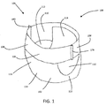
FIG. 1 is a schematic, perspective view of a diaper pant. -
FIG. 2A is a partially cut-away, plan view of a diaper pant. -
FIG. 2B is a partially cut-away, plan view of a diaper pant. -
FIG. 3A is a cross-sectional view of the diaper pant ofFIGS. 2A and2B taken alongline 3A-3A. -
FIG. 3B is a cross-sectional view of the diaper pant ofFIGS. 2A and2B taken alongline 3B-3B. -
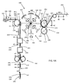
FIG. 4A is a schematic, side elevation view of a converting apparatus. -
FIG. 4B is a schematic, plan view of a continuous length of chassis assemblies taken alonglines 4B-4B inFIG. 4A . -
FIG. 4C is a schematic, plan view of a discrete chassis having a longitudinal axis parallel with a machine direction taken alongline 4C-4C inFIG. 4A . -
FIG. 4D is a schematic, plan view of a discrete chassis having a lateral axis parallel with the machine direction taken alongline 4D-4D inFIG. 4A . -
FIG. 4E is a schematic, plan view of continuous lengths of first and second elastic belt substrates taken alonglines 4E-4E inFIG. 4A . -
FIG. 4F is a schematic, plan view of a continuous length of diaper pants taken alongline 4F-4F inFIG. 4A . -
FIG. 4G is a schematic, plan view of a continuous length of folded diaper pants taken alongline 4G-4G inFIG. 4A . -
FIG. 4H is a schematic, plan view of a discrete diaper pant taken along line 4H-4H inFIG. 4A . -
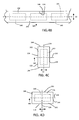
FIG. 5 is a perspective, side view of a rotary cutting apparatus. -
FIG. 6 is a side elevation view of a rotary cutting apparatus located adjacent to a transfer apparatus. -
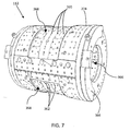
FIG. 7 is a perspective view of a cutting roll. -
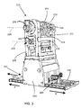
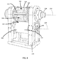
FIG. 8 is a perspective view of a portion of a rotary cutting apparatus. -
FIG. 9 is a perspective view of a first stationary member and a second stationary member connected with a track of a rotary cutting apparatus. -
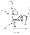
FIG. 10 is a perspective view of a first stationary member. -
FIG. 11 is a plan view of a first stationary member and a second stationary member connected with a track of a rotary cutting apparatus. -
FIG. 12 is a perspective view of a second stationary member connected with a track of a rotary cutting apparatus. -
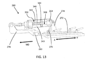
FIG. 13 is a perspective view of a second stationary member. -
FIG. 14 is a perspective view of a rotary cutting apparatus. - The following definitions may be useful in understanding the present disclosure:
- "Absorbent article" is used herein to refer to consumer products whose primary function is to absorb and retain soils and wastes. "Diaper" is used herein to refer to an absorbent article generally worn by infants and incontinent persons about the lower torso. The term "disposable" is used herein to describe absorbent articles which generally are not intended to be laundered or otherwise restored or reused as an absorbent article (e.g., they are intended to be discarded after a single use and may also be configured to be recycled, composted or otherwise disposed of in an environmentally compatible manner).
- "Longitudinal" means a direction running substantially perpendicular from a waist edge to a longitudinally opposing waist edge of an absorbent article when the article is in a flat out, uncontracted state, or from a waist edge to the bottom of the crotch, i.e. the fold line, in a bi-folded article. Directions within 45 degrees of the longitudinal direction are considered to be "longitudinal." "Lateral" refers to a direction running from a longitudinally extending side edge to a laterally opposing longitudinally extending side edge of an article and generally at a right angle to the longitudinal direction. Directions within 45 degrees of the lateral direction are considered to be "lateral."
- "Substrate" refers herein to a material that is primarily two-dimensional (i.e. in an XY plane) and whose thickness (in a Z direction) is relatively small (i.e. 1/10 or less) in comparison to the substrate's length (in an X direction) and width (in a Y direction). Non-limiting examples of substrates include a web, layer or layers or fibrous materials, nonwovens, films and foils such as polymeric films or metallic foils. These materials may be used alone or may comprise two or more layers. As such, a web is a substrate.
- "Machine direction" (MD) refers herein to the direction of material flow through a process. In addition, relative placement and movement of material can be described as flowing in the machine direction through a process from upstream in the process to downstream in the process.
- "Cross direction" (CD) refers herein to a direction that is not parallel with, and usually perpendicular to, the machine direction.
- "Pant" (also referred to as "training pant", "pre-closed diaper", "diaper pant", "pant diaper", and "pull-on diaper") refers herein to disposable absorbent articles having a continuous perimeter waist opening and continuous perimeter leg openings designed for infant or adult wearers. A pant can be configured with a continuous or closed waist opening and at least one continuous, closed, leg opening prior to the article being applied to the wearer. A pant can be preformed by various techniques including, but not limited to, joining together portions of the article using any refastenable and/or permanent closure member (e.g., seams, heat bonds, pressure welds, adhesives, cohesive bonds, mechanical fasteners, etc.). A pant can be preformed anywhere along the circumference of the article in the waist region (e.g., side fastened or seamed, front waist fastened or seamed, rear waist fastened or seamed).
- "Pre-fastened" refers herein to pant diapers manufactured and provided to consumers in a configuration wherein the front waist region and the back waist region are fastened or connected to each other as packaged, prior to being applied to the wearer. As such pant diapers may have a continuous perimeter waist opening and continuous perimeter leg openings designed for infant or adult wearers. Pant diapers can be preformed anywhere along the circumference of the waist region (e.g., side fastened or connected, front waist fastened or connected, rear waist fastened or connected).
- Aspects of the present disclosure involve methods and apparatuses for manufacturing absorbent articles, and more particularly, methods and apparatuses for controlling the position of a rotary cutting apparatus during the manufacture of absorbent articles. As discussed in more detail below, the rotary cutting apparatus is configured in a first mode of operation, referred to herein as an operating configuration, and in a second mode of operation, referred to herein as a fail-safe configuration. In the operating configuration, the rotary cutting apparatus is configured to cut a continuous length of chassis assemblies into discrete chassis. The rotary cutting apparatus is configured with a sensor to detect a defective operation condition, such as a continuous web wrapping around the cutting roll. If the sensor detects a defective operating condition, the rotary cutting apparatus is configured to switch from the operating configuration to the fail-safe configuration in order to prevent damage to the rotary cutting apparatus and/or adjacent equipment.
- A rotary cutting apparatus comprises a frame that is movable in a first direction and a second direction, wherein the first direction is opposite the second direction. The rotary cutting apparatus may also include a track. The frame is moveably connected with the track. In some instances, the frame may be slideably connected with the track. The rotary cutting apparatus includes a cutting roll defining a first longitudinal axis. The cutting roll is rotatably connected with the frame and configured to rotate about the first longitudinal axis. The rotary cutting apparatus also includes an anvil roll defining a second longitudinal axis. The anvil roll is rotatably connected with the frame and configured to rotate about the second longitudinal axis. The anvil roll is positioned relative to the cutting roll such that the first longitudinal axis is substantially parallel with the second longitudinal axis. The rotary cutting apparatus includes a first stationary member adapted to prevent movement of the frame in the first direction. The rotary cutting apparatus includes a second stationary member connected with the frame. The second stationary member has a first configuration and a second configuration. In the first configuration, the second stationary member prevents movement of the frame in the second direction. Also, in the first configuration, the second stationary member may be adapted to apply a positive force to the frame in the first direction. In the second configuration, the second stationary member allows movement of the frame in the second direction. In some exemplary configurations, the first longitudinal axis is orthogonal to the first and second directions. The rotary cutting apparatus further comprises a sensor that is adapted to detect a defective operating condition. If the sensor detects a defecting operating condition, the second stationary member shifts from the first configuration to the second configuration.
- With the rotary cutting apparatus in an operating configuration, the second stationary member is set in the first configuration. In operation, a continuous substrate advances in a machine direction between the cutting roll and the anvil roll to be cut into discrete components. If the sensor detects a defective operating condition, the rotary cutting apparatus switches from the operating configuration to the fail-safe configuration and the second stationary member switches from the first configuration to the second configuration. As a result, the frame is able to move in the second direction as the continuous length of chassis assemblies wrap around the cutting roll.
- While the apparatuses and methods of the present disclosure are discussed in the context of cutting continuous lengths of chassis assemblies that may be used in the assembly of pant diapers, it is to be appreciated that the rotary cutting apparatus of the present disclosure may be used to cut substrates into various components that may be used in the manufacture of absorbent articles.
- As previously mentioned, the methods and apparatuses discussed herein may be used to manufacture absorbent articles. To help provide additional context to the subsequent discussion, the following provides a general description of absorbent articles in the form of diaper pants that may be manufactured in accordance with the methods and apparatuses disclosed herein. While the present disclosure relates to cutting continuous lengths of chassis assemblies for diaper pants, it is to be appreciated that the methods and apparatuses disclosed herein may be used with various types of absorbent articles.
-
FIGS. 1 and2A show an exemplaryabsorbent article 100 in the form of adiaper pant 101 that may be formed in accordance with the apparatuses and methods disclosed herein. In particular,FIG. 1 is a perspective view of adiaper pant 101 in a pre-fastened configuration andFIG. 2A shows a plan view of thediaper pant 101 with the portion of thediaper pant 101 that faces away from a wearer oriented toward the viewer. Thediaper pant 101 shown inFIGS. 1 and2A includes achassis 102 and a ring-likeelastic belt 104. As discussed below in more detail, A firstelastic belt 106 and a secondelastic belt 108 are connected together to form the ring-likeelastic belt 104. - With continued reference to
FIG. 2A , thechassis 102 includes afirst waist region 116, asecond waist region 118, and acrotch region 120 disposed intermediate the first andsecond waist regions first waist region 116 may be configured as a front waist region, and thesecond waist region 118 may be configured as back waist region. In some embodiments, the length of each of thefront waist region 116, backwaist region 118, andcrotch region 120 may be one-third of the length of theabsorbent article 100. Thediaper pant 101 may also include a laterally extendingfront waist edge 121 in thefront waist region 116 and a longitudinally opposing and laterally extending backwaist edge 122 in theback waist region 118. To provide a frame of reference for the present discussion, thediaper pant 101 andchassis 102 ofFIG. 2A are shown with alongitudinal axis 124 and alateral axis 126. In some embodiments, thelongitudinal axis 124 may extend through thefront waist edge 121 and through theback waist edge 122. Thelateral axis 126 may extend through a first longitudinal orright side edge 128 and through a midpoint of a second longitudinal orleft side edge 130 of thechassis 102. - As shown in
FIGS. 1 and2A , thediaper pant 101 may include an inner,body facing surface 132, and an outer,garment facing surface 134. Thechassis 102 may include abacksheet 136 and atopsheet 138. Thechassis 102 may also include anabsorbent assembly 140, including an absorbent core 142, disposed between a portion of thetopsheet 138 and thebacksheet 136. As discussed in more detail below, thediaper pant 101 may also include other features, such asleg elastics 156 and/or leg cuffs to enhance the fit around the legs of the wearer. - As shown in
FIG. 2A , the periphery of thechassis 102 may be defined by the firstlongitudinal side edge 128, a secondlongitudinal side edge 130, a first laterally extendingend edge 144 disposed in thefirst waist region 116, and a second laterally extendingend edge 146 disposed in thesecond waist region 118. Both side edges 128 and 130 extend longitudinally between thefirst end edge 144 and thesecond end edge 146. As shown inFIG. 2A , the laterally extendingend edges front waist edge 121 in thefront waist region 116 and the laterally extending backwaist edge 122 in theback waist region 118. When thediaper pant 101 is worn on the lower torso of a wearer, thefront waist edge 121 and theback waist edge 122 of thechassis 102 may encircle a portion of the waist of the wearer. At the same time, the chassis side edges 128 and 130 may encircle at least a portion of the legs of the wearer. And thecrotch region 120 may be generally positioned between the legs of the wearer with the absorbent core 142 extending from thefront waist region 116 through thecrotch region 120 to theback waist region 118. - Referring to
FIG. 2A , thediaper pant 101 may also include elasticized leg cuffs 156. It is to be appreciated that the leg cuffs 156 can be and are sometimes also referred to as leg bands, side flaps, barrier cuffs, elastic cuffs or gasketing cuffs. The elasticized leg cuffs 156 may be configured in various ways to help reduce the leakage of body exudates in the leg regions. - Diaper pants may be manufactured with a ring-like
elastic belt 104 and provided to consumers in a configuration wherein thefront waist region 116 and theback waist region 118 are connected to each other as packaged, prior to being applied to the wearer. As such, diaper pants 101 may have a continuousperimeter waist opening 110 and continuousperimeter leg openings 112 such as shown inFIG. 1 . The ring-likeelastic belt 104 is defined by a firstelastic belt 106 connected with a secondelastic belt 108. As shown inFIG. 2A , the firstelastic belt 106 defines first and second opposingend regions central region 106c, and the second elastic 108 belt defines first and second opposingend regions central region 108c. Thecentral region 106c of the firstelastic belt 106 is connected with thefirst waist region 116 of thechassis 102, and thecentral region 108c of the secondelastic belt 108 is connected with thesecond waist region 118 of thechassis 102.FIGS. 1 and2A , thefirst end region 106a of the firstelastic belt 106 is connected with thefirst end region 108a of the secondelastic belt 108 atfirst side seam 178, and thesecond end region 106b of the firstelastic belt 106 is connected with thesecond end region 108b of the secondelastic belt 108 atsecond side seam 180 to define the ring-likeelastic belt 104 as well as thewaist opening 110 andleg openings 112. - Referring to
FIGS. 2A ,3A, and 3B , the firstelastic belt 106 also defines an outerlateral edge 107a and an innerlateral edge 107b, and the secondelastic belt 108 defines an outerlateral edge 109a and an innerlateral edge 109b. The outerlateral edges front waist edge 121 and the laterally extending backwaist edge 122. The firstelastic belt 106 and the secondelastic belt 108 may also each include an outer,garment facing layer 174 and an inner,wearer facing layer 176. It is to be appreciated that the firstelastic belt 106 and the secondelastic belt 108 may comprise the same materials and/or may have the same structure. In some embodiments, the firstelastic belt 106 and the second elastic belt may comprise different materials and/or may have different structures. It should also be appreciated that the firstelastic belt 106 and the secondelastic belt 108 may be constructed from various materials. For example, the first and second belts may be manufactured from materials such as plastic films; apertured plastic films; woven or nonwoven webs of natural materials (e.g., wood or cotton fibers), synthetic fibers (e.g., polyolefins, polyamides, polyester, polyethylene, or polypropylene fibers) or a combination of natural and/or synthetic fibers; or coated woven or nonwoven webs. In some embodiments, the first and second elastic belts include a nonwoven web of synthetic fibers, and may include a stretchable nonwoven. In other embodiments, the first and second elastic belts include an inner hydrophobic, non-stretchable nonwoven material and an outer hydrophobic, non-stretchable nonwoven material. - The first and second
elastic belts outer layer 174 and theinner layer 176. The belt elastic material may include one or more elastic elements such as strands, ribbons, or panels extending along the lengths of the elastic belts. As shown inFIGS. 2A ,3A, and 3B , the belt elastic material may include a plurality ofelastic strands 168, which may be referred to herein as outer, waist elastics 170 and inner, waist elastics 172. As shown inFIG. 2A , theelastic strands 168 continuously extend laterally between the first and second opposingend regions elastic belt 106 and between the first and second opposingend regions elastic belt 108. In some embodiments, someelastic strands 168 may be configured with discontinuities in areas, such as for example, where the first and secondelastic belts absorbent assembly 140. In some embodiments, theelastic strands 168 may be disposed at a constant interval in the longitudinal direction. In other embodiments, theelastic strands 168 may be disposed at different intervals in the longitudinal direction. The belt elastic material in a stretched condition may be interposed and joined between the uncontractedouter layer 174 and the uncontractedinner layer 176. When the belt elastic material is relaxed, the belt elastic material returns to an unstretched condition and contracts theouter layer 174 and theinner layer 176. The belt elastic material may provide a desired variation of contraction force in the area of the ring-like elastic belt. - It is to be appreciated that the
chassis 102 andelastic belts FIG. 2A . For example,FIG. 2B shows a plan view of adiaper pant 101 having the same components as described above with reference toFIG. 2A , except the first laterally extendingend edge 144 of thechassis 102 is aligned along and coincides with thefront waist edge 121 of thepant 101, and the second laterally extendingend edge 146 is aligned along and coincides with theback waist edge 122 of thepant 101. - Components of the disposable absorbent article (i.e., diaper, disposable pant, adult incontinence article, sanitary napkin, pantiliner, etc.) described in this specification can at least partially be comprised of bio-sourced content as described in
US 2007/0219521A1 Hird et al published on September 20, 2007 ,US 2011/0139658A1 Hird et al published on June 16, 2011 ,US 2011/0139657A1 Hird et al published on June 16, 2011 ,US 2011/0152812A1 Hird et al published on June 23, 2011 ,US 2011/0139662A1 Hird et al published on June 16, 2011 , andUS 2011/0139659A1 Hird et al published on June 16, 2011 . These components include, but are not limited to, topsheet nonwovens, backsheet films, backsheet nonwovens, side panel nonwovens, barrier leg cuff nonwovens, super absorbent, nonwoven acquisition layers, core wrap nonwovens, adhesives, fastener hooks, and fastener landing zone nonwovens and film bases. - In at least one exemplary configuration, a disposable absorbent article component comprises a bio-based content value from about 10% to about 100% using ASTM D6866-10, method B, in another embodiment, from about 25% to about 75%, and in yet another embodiment, from about 50% to about 60% using ASTM D6866-10, method B.
- In order to apply the methodology of ASTM D6866-10 to determine the bio-based content of any disposable absorbent article component, a representative sample of the disposable absorbent article component must be obtained for testing. In at least one embodiment, the disposable absorbent article component can be ground into particulates less than about 20 mesh using known grinding methods (e.g., Wiley® mill), and a representative sample of suitable mass taken from the randomly mixed particles.
- As previously discussed, the apparatuses and methods of the present disclosure may be utilized to assemble various components of pre-fastened diaper pants 101. For example,
FIG. 4A shows a schematic view of a convertingapparatus 200 adapted to manufacture diaper pants 101. The method of operation of the convertingapparatus 200 may be described with reference to the various components ofdiaper pant 101 described above and shown inFIGS. 1 and2A . Although the following methods are provided in the context of the diaper pants 101 shown inFIGS. 1 and2A , it is to be appreciated that various embodiments of diaper pants can be manufactured according the methods disclosed herein, such as for example, the absorbent articles disclosed inU.S. Patent No. 7,569,039, filed on November 10, 2004 ;U.S. Patent Publication No. 2005/0107764, published May 19, 2005 ;U.S. Patent Application No. 2012/0061016, published March 15, 2012 ; andU.S. Patent Publication No. 2012/0061015, published March 15, 2012 . - With reference to
FIG. 4A , and as discussed in more detail below, in an operating configuration, a convertingapparatus 200 operates to advance a continuous length ofchassis assemblies 202 along a machine direction MD such that the longitudinal axis is parallel with the machine direction MD. The continuous length ofchassis assemblies 202 are cut intodiscrete chassis 102. Thediscrete chassis 102 are then rotated and advanced in the machine direction MD such that the lateral axis is parallel with the machine direction MD. Thediscrete chassis 102 are combined with continuous lengths of advancing first and secondelastic belt substrates discrete chassis 102 are then folded along the lateral axis to bring the first and secondelastic belt substrates elastic belt substrates elastic belt substrates - As shown in
FIGS. 4A and4B , a continuous length ofchassis assemblies 202 is advanced in a machine direction MD to arotary cutting apparatus 210. Therotary cutting apparatus 210 includes a cuttingroll 212 that defines a firstlongitudinal axis 218 and ananvil roll 214 that defines a secondlongitudinal axis 220. Theanvil roll 214 is positioned relative to the cuttingroll 212 such that the firstlongitudinal axis 218 is substantially parallel with the secondlongitudinal axis 220. The cuttingroll 212 and theanvil roll 214 are defined by outercircumferential surfaces member 216 may extend radially outward from the outercircumferential surface 224 of the cuttingroll 212. The cuttingroll 212 may be configured with vacuum pressure to hold the continuous length ofchassis assemblies 202 on the cuttingroll 212. - With reference to
FIGS. 4A and5 , in operation, a continuous length ofchassis assemblies 202 advances onto the outercircumferential surface 224 of the cuttingroll 212. The continuous length ofchassis assemblies 202 advances through a nip 222 formed between the cuttingroll 212 and theanvil roll 214. The cuttingmember 216 compresses the continuous length ofchassis assemblies 202 against the outercircumferential surface 226 of theanvil roll 214. As a result, the compressive force cuts the continuous length ofchassis assemblies 202 intodiscrete chassis 102, such as shown inFIG. 4C . In order for the cuttingmember 216 to rotate beyond theanvil roll 214, the cuttingmember 216 may be configured to flex away from the outercircumferential surface 226 of theanvil roll 214. The continuous length ofchassis assemblies 202 may include absorbent assemblies sandwiched between topsheet material and backsheet material, leg elastics, barrier leg cuffs and the like. - With continued reference to
FIG. 4A , the cuttingroll 212 continues to rotate and advance thediscrete chassis 102 in the machine direction MD toward agap 252 between the cuttingroll 212 and thetransfer apparatus 244. Thediscrete chassis 102 is then transferred from the cuttingroll 212 to thetransfer apparatus 244. With reference toFIGS. 4A and6 , thetransfer apparatus 244 may rotate about alongitudinal axis 246 and may include a plurality oftransfer members 248. Thetransfer members 248 may rotate about an axis ofrotation 250 that is orthogonal to thelongitudinal axis 246. As thediscrete chassis 102 approaches thetransfer apparatus 244, vacuum may be intermittently interrupted from the cuttingroll 212. At the same time positive blow-off pressure may be applied to thediscrete chassis 102 from the outercircumferential surface 224 of the cuttingroll 212 to assist thediscrete chassis 102 in transferring from the cuttingroll 212. Thetransfer members 248 may be configured with vacuum to hold thediscrete chassis 102. Once thediscrete chassis 102 is removed from the cuttingroll 212, the cuttingroll 212 continues to rotate in order to advance and cut a subsequent discrete chassis. - The
discrete chassis 102 advances onto thetransfer members 248 in the orientation shown inFIG. 4C where thelongitudinal axis 124 is parallel with the machine direction MD. Thetransfer apparatus 244 shown inFIGS. 4A and6 operates to advance thediscrete chassis 102 in the machine direction MD while concurrently rotating thediscrete chassis 102. Thetransfer apparatus 244 may reorient thediscrete chassis 102 to the orientation shown inFIG. 4D where thelateral axis 126 is parallel with the machine direction MD. It is to be appreciated that various forms of transfer apparatuses may be used with the methods and apparatuses disclosed herein, such as methods and apparatuses for transferring discrete articles disclosed inU.S. Patent Application No. 13/447,531, filed on Apr. 16, 2012 U.S. Patent Application No. 13/447,544, filed on Apr. 16, 2012 U.S. Patent Application No. 13/447,568, filed on Apr. 16, 2012 U.S. Patent Application No. 13/447,585, filed on Apr. 16, 2012 - As shown in
FIG. 4A , thediscrete chassis 102 is transferred from thetransfer apparatus 244 and combined with advancing, continuous lengths of first andsecond belt substrates FIG. 4E . The continuous lengths of first andsecond belt substrates elastic belts discrete chassis 102 is transferred from thetransfer apparatus 244 to a nip 234 formed between thetransfer apparatus 244 and acarrier apparatus 236. At thenip 234, thediscrete chassis 102 is combined with the continuous lengths of advancing first andsecond belt substrates absorbent articles 204. As shown inFIG. 4F , awearer facing surface 133 of thefirst belt substrate 206 may be joined with thegarment facing surface 134 of thechassis 102 along thefirst waist region 116, and awearer facing surface 133 of thesecond belt substrate 208 may be joined with thegarment facing surface 134 of thechassis 102 along thesecond waist region 118. As shown inFIG. 4A , adhesive 190 may be applied to thewearer facing surface 133 of the first andsecond belt substrates adhesive applicator 192 before combining with thediscrete chassis 102 at thenip 234. With reference toFIG. 4F , a continuous length ofabsorbent articles 204 is defined by multiplediscrete chassis 102 spaced apart from each other along the machine direction MD and connected with each other by the first andsecond belt substrates - As shown in
FIG. 4A , the continuous length ofabsorbent articles 204 advances from thenip 234 to afolding apparatus 254. With reference toFIGS. 2A ,3A , and4F , at thefolding apparatus 254, eachchassis 102 is folded in the cross direction CD along alateral axis 126 to place thefirst waist region 116, and specifically, the inner,wearer facing surface 132 into a facing, surface to surface arrangement with the inner, wear facingsurface 132 of thesecond waist region 118. With reference toFIGS. 2A and4F , the folding of thechassis 102 also positions thewearer facing surface 133 of thefirst belt substrate 206 in a facing relationship with thewearer facing surface 133 of thesecond belt substrate 208. - Referring to
FIG. 4A , the foldeddiscrete chassis 102 connected with the first andsecond belt substrates folding apparatus 254 to abonder apparatus 256. Thebonder apparatus 256 operates to bond anoverlap area 166 of the first andsecond belt substrates regions 160, as shown inFIG. 4G . Theoverlap area 166 includes a portion of thefirst belt substrate 206 extending between eachchassis 102 and a portion of thesecond belt substrate 208 extending between eachchassis 102. As shown inFIG. 4A , the continuous length ofabsorbent articles 204 are advanced from thebonder apparatus 256 to acutter 286, shown in the form of a cutting roll for purposes of illustration, where the bondedregions 160 are cut into along the cross direction CD to create afirst side seam 178 on adiaper pant 101 and asecond side seam 180 on a subsequently advancingdiaper pant 101, such as shown inFIG. 4H . - As shown in
FIG. 5 , the cuttingroll 212 and theanvil roll 214 may be configured to rotate about a firstlongitudinal axis 218 and a secondlongitudinal axis 220. Referring toFIG. 5 , in some exemplary configurations, the cuttingroll 212 may be connected with ashaft 238 and theanvil roll 214 may be connected with ashaft 240. The cuttingroll 212 and theanvil roll 214 may be connected withshafts anvil roll 214 may rotate independent from the cuttingroll 212. For example, the cuttingroll 212 and/or theanvil roll 214 may be configured to rotate using gears, belts, or direct couplings. In other exemplary configurations, theanvil roll 214 may be driven by bearer rings on the cuttingroll 212. As such, theanvil roll 214 may be a "walking" type anvil roll. - As previously mentioned, the cutting
roll 212 may be configured to apply vacuum pressure to the chassis assemblies advancing on the outercircumferential surface 224 of the cuttingroll 212. For example, as shown inFIG. 7 , the cuttingroll 212 may include a plurality ofvacuum apertures 360 in the outercircumferential surface 224. Vacuum may be supplied to thevacuum apertures 360 from a vacuum source. For example, negative, vacuum pressure may enter the cuttingroll 212 through thecenter 366 of the cuttingroll 212. It is to be appreciated that negative, vacuum pressure may enter the cuttingroll 212 at various locations on the cuttingroll 212. - With reference to
FIGS. 5-7 , in some exemplary configurations, vacuum may be intermittently interrupted from the cuttingroll 212 in order to assist the discrete chassis assemblies in transferring from the cuttingroll 212 to thetransfer apparatus 244. Once vacuum pressure is turned off to the cuttingroll 212, the negative, vacuum pressure may be canceled by introducing compressed air to thevacuum apertures 360. For example, compressed air may enter through thecenter 366 of the cuttingroll 212 at the same location where the vacuum pressure enters the cuttingroll 212. The compressed air acts to increase the pressure applied through thevacuum apertures 360 to atmospheric or near atmospheric air pressure. - The cutting
roll 212 may also be configured to apply positive, blow-off pressure to the discrete chassis assemblies in order to assist the discrete chassis assemblies in transferring from the cuttingroll 212 to thetransfer apparatus 244. As shown inFIG. 7 , the cuttingroll 212 may include a plurality of blow-offapertures 362 in the outercircumferential surface 224. In some exemplary configurations, positive, blow-off pressure may be applied to the chassis assemblies through the blow-off apertures 362. Compressed air may enter the cuttingroll 212 through a blow-offmanifold 364 that is connected with the cuttingroll 212. The compressed or atmospheric air may apply a positive force to the discrete chassis assemblies through the blow-off apertures 362. As a result, the discrete chassis assemblies may move away from the outercircumferential surface 224 of the cuttingroll 212. Referring toFIGS. 4A and7 , the blow-offmanifold 364 may be configured to apply a positive force to the chassis assembly for a portion of the time that the discrete chassis advances on the cuttingroll 212. For example, the blow-offmanifold 364 may be configured to apply positive force to thediscrete chassis 102 assembly as thediscrete chassis 102 is advancing through thegap 252 between the cuttingroll 212 to thetransfer apparatus 244. - It is to be appreciated that the vacuum pressure and blow-off pressure may be controlled independently of each other in order to control the movement of the
discrete chassis 102 as thediscrete chassis 102 advances on the outercircumferential surface 224 of the cuttingroll 212. - The outer
circumferential surface 224 of the cuttingroll 212 may include one or more recessedregions 368 as shown inFIG. 7 . The recessedregions 368 may be configured to hold an absorbent assembly of a discrete chassis. The recessedregions 368 may allow the absorbent assembly to expand in caliper as the chassis assemblies advance on the cuttingroll 212. Referring toFIG. 8 , the recessedregions 368 may reduce the compressive force applied to the absorbent assemblies as the chassis assemblies advance through thenip 222 between the cuttingroll 212 and theanvil roll 214. - In some exemplary configurations, the outer
circumferential surface 224 of the cuttingroll 212 may be configured to have a relatively high coefficient of friction to assist the cuttingroll 212 in holding the discrete chassis in a fully extended configuration. For example, the outercircumferential surface 224 of the cuttingroll 212 may be plasma coated. - Referring to
FIG. 8 , the cuttingmember 216 may comprise various materials that are capable of flexing away from the outercircumferential surface 226 of theanvil roll 214. For example, the cuttingmember 216 may comprise tungsten carbide or tool steel. In other exemplary configurations, the cuttingmember 216 may comprise a rigid material. In an exemplary configuration where the cuttingmember 216 comprises a rigid material, the rotary cutting apparatus may be configured as a rotary die cutter. In an exemplary configuration where the cutting member is made of a rigid material, the cuttingroll 212 may be configured with a spring, such as a goose-neck spring. The spring may flex when the cuttingmember 216 compresses the continuous length ofchassis assemblies 202 against the outercircumferential surface 226 of theanvil roll 214 in order to advance the cuttingmember 216 past the outercircumferential surface 226 of theanvil roll 214. - The
anvil roll 214 may comprise various materials, such as tungsten carbide or tool steel. The outercircumferential surface 226 of theanvil roll 214 may comprise various materials that are integral with, or separate from, theanvil roll 214 material. - As shown in
FIG. 8 , in some exemplary configurations, the cuttingroll 212 may be fixed to aframe 228 and theanvil roll 214 may be loaded to the cuttingroll 212. In other exemplary configurations, theanvil roll 214 may be fixed to theframe 228 and the cuttingroll 212 may be loaded to theanvil roll 214. Various systems may be used to load theanvil roll 214 to the cuttingroll 212 or to load the cuttingroll 212 to theanvil roll 214. For example, loading systems may include pneumatic cylinders, hydraulic systems, air-over-oil systems, springs, linkages, or actuators. It is to be appreciated that the distance from the axis ofrotation 218 of the cuttingroll 212 and the axis ofrotation 220 of theanvil roll 214 may affect the force applied to the continuous length of chassis assemblies by the cuttingmember 216. - Referring to
FIGS. 4A and 6-8 , during operation, the continuous length ofchassis assemblies 202 advances onto the outercircumferential surface 224 of the cuttingroll 212. Vacuum may be applied to thechassis assemblies 202 through thevacuum apertures 360 in the cuttingroll 212. As the continuous length ofchassis assemblies 202 advance through thenip 222 between the cuttingroll 212 and theanvil roll 214, the cuttingmember 216 compresses thechassis assemblies 202 against the outercircumferential surface 226 of theanvil roll 214. The force of the cuttingmember 216 compressing thechassis assemblies 202 against theanvil roll 214 cuts the continuous length ofchassis assemblies 202 intodiscrete chassis 102. Vacuum may be used to hold the discrete chassis in an extended configuration. - Next, the
discrete chassis 102 is transferred to thetransfer apparatus 244. Thediscrete chassis 102 advances through thegap 252 between the cuttingroll 212 and thetransfer apparatus 244. Positive air pressure may be introduced through thecenter 366 of the cuttingroll 212 in order to cancel the vacuum pressure applied through thevacuum apertures 360. In addition, positive air pressure may be applied through the blow-offmanifold 364, to the blow-offapertures 362, and then to thediscrete chassis 102. As positive air pressure is applied to thediscrete chassis 102, vacuum pressure may be applied to thediscrete chassis 102 by thetransfer members 248 of thetransfer apparatus 244. As a result, thediscrete chassis 102 transfers from the cuttingroll 212 to thetransfer member 248. - As discussed above, various defective operating conditions may cause continuous length of
chassis assemblies 202 to be incompletely cut by thecutting apparatus 210. For example, the cuttingmember 216 may become dull through extended use. In another example, the outercircumferential surface 224 of cuttingroll 212 and/or the cuttingmember 216 may become contaminated with materials, such as adhesive. As a result, the continuous length ofchassis assemblies 202 may not transfer to thetransfer apparatus 244, but, instead, the continuous length ofchassis assemblies 202 may begin to undesirably wrap around the cuttingroll 212. The continuous length ofchassis assemblies 202 may continue to wrap around the cuttingroll 212 such that the continuous length ofchassis web 202 expands radially around the outercircumferential surface 224 of the cuttingroll 212 and begins to fill thegap 252 between the cuttingroll 212 and thetransfer apparatus 244. As such, thetransfer apparatus 244 may collide with the wrappedchassis assemblies 202, which in turn, may induce a relatively high force on therotary cutting apparatus 210 and thetransfer apparatus 244 at thegap 252. Consequently, the cuttingroll 212 and/or adjacent equipment may be damaged. As mentioned above, and as discussed in more detail below, therotary cutting apparatus 210 may be configured with modes of operation that allows thegap 252 to increase in length such that the continuous length ofchassis web 202 may continue wrapping around the cuttingroll 212 without interfering with thetransfer apparatus 244 until the convertingapparatus 200 can be safely shut down. - For example, the
rotary cutting apparatus 210 shown inFIGS. 5 and6 may be configured in two modes of operation. In particular, therotary cutting apparatus 210 may be configured in a first mode of operation, referred to as an operating configuration, where therotary cutting apparatus 210 is configured to cut the continuous length of chassis assemblies into discrete chassis. In a second mode of operation, referred to as a fail-safe configuration, therotary cutting apparatus 210 is configured to adjust the length of thegap 252 to prevent damage to therotary cutting apparatus 210 and/or adjacent equipment. As shown inFIG. 5 , therotary cutting apparatus 210 may include aframe 228 that is movable in a first direction, A, and in a second direction B, wherein the first direction A is opposite the second direction, B. The first direction, A, may be the machine direction MD. Theframe 228 may be moveably connected with atrack 230. Therotary cutting apparatus 210 may include a cuttingroll 212 defining a firstlongitudinal axis 218. The cuttingroll 212 may be rotatably connected with theframe 228 and configured to rotate about the firstlongitudinal axis 218. Therotary cutting apparatus 210 may include ananvil roll 214 defining a secondlongitudinal axis 220. Theanvil roll 214 may be rotatably connected with theframe 228 and configured to rotate about the secondlongitudinal axis 220. Theanvil roll 214 may be positioned relative to the cuttingroll 212 such that the firstlongitudinal axis 218 is substantially parallel with the secondlongitudinal axis 220. The firstlongitudinal axis 218 and the secondlongitudinal axis 220 may be orthogonal to the first and second directions, A and B. A nip 222 is formed between theanvil roll 214 and the cuttingroll 212. - As shown in
FIG. 9 , therotary cutting apparatus 210 may include a firststationary member 262 and a secondstationary member 260. The firststationary member 262 may be connected with one end of thetrack 230 and the secondstationary member 260 may be connected with the opposite end of thetrack 230. The firststationary member 262 may be adapted to limit the movement of theframe 228 in the first direction, A. The secondstationary member 260 may be adapted to limit movement of theframe 228 in the second direction, B. In addition, the secondstationary member 260 may be adapted to apply a positive force to theframe 228 in the first direction, A, to hold theframe 228 against the firststationary member 262. As such, with the rotary cutting apparatus in an operating configuration, the firststationary member 262 and the secondstationary member 260 operate to fix theframe 228 in a desired location. - With reference to
FIGS. 9-11 , a firststationary member 262 that is selectively connectable with lockingapertures 232 on thetrack 230. For clarity, various components, such as the frame, are not shown inFIGS. 9-11 . The firststationary member 262 includes a lockingmember 290 connected with abase 288. The lockingmember 290 may be adapted to selectively connect with each lockingapertures 232 on thetrack 230. The firststationary member 262 also includes astop member 292 that extends in the second direction, B. As discussed in more detail below, thestop member 292 may align with astop member 296 that is connected with theframe 228. Thestop member 296 may be connected with a joiningmember 294 that is connected with theframe 228. - As previously mentioned, the
rotary cutting apparatus 210 may include a secondstationary member 260, such as shown inFIGS. 5 ,11 , and12 . The secondstationary member 260 may be configured in a first configuration and in a second configuration. When therotary cutting apparatus 210 is configured in an operating configuration, the secondstationary member 260 may be configured in the first configuration. As shown inFIGS. 5 and11 , in the first configuration, the secondstationary member 260 is adapted to limit the movement of theframe 228 in the second direction, B. The secondstationary member 260 may be configured to also apply a positive force to theframe 228 in the first direction, A. When therotary cutting apparatus 210 is configured in a fail-safe configuration, the secondstationary member 260 may be configured in a second configuration. In a second configuration, the secondstationary member 260 is adapted to allow theframe 228 to move in the second direction, B, on thetrack 230. - With continuing reference to
FIGS. 5 ,11 , and12 , the second stationary member may include a base 272 that is connected with thetrack 230 of therotary cutting apparatus 210. The secondstationary member 260 may also include afirst arm 274. Thefirst arm 274 may be connected with the base 272 at one end and with a reciprocatingmember 264 at an opposite end of thefirst arm 274. Thefirst arm 274 may be moveably connected with thebase 272. For example, thefirst arm 274 may be slideably connected with thebase 272. A lockingmember 276 may be used to fix thefirst arm 274 with thebase 272. The reciprocatingmember 264 may be pivotally connected with thefirst arm 274 at one end and pivotally connected with asecond arm 278 at an opposite end of the reciprocatingmember 264. Thesecond arm 278 may be connected with a joiningmember 280. The joiningmember 280 may be connected with theframe 228 of therotary cutting apparatus 210, such as shown inFIG. 9 . - The reciprocating member may be configured in various ways. For example, as shown in
FIGS. 12 and13 , the reciprocatingmember 264 may be configured as apneumatic cylinder 340. Thepneumatic cylinder 340 includes acylinder barrel 342, apiston 344, and apiston rod 346 connected with thepiston 344 as shown inFIG. 13 . Thepiston 344 may be located inside of thecylinder barrel 342 and may separate the inside of thecylinder barrel 342 into afirst chamber 348 and asecond chamber 350. Thepiston rod 346 may be connected to thepiston 344 and may extend in the first direction A, through thesecond chamber 350. Exemplary pneumatic cylinders are manufactured by Festo Corporation of Hauppauge, New York, model 163368, DNC-50-75-PPV-A. WhileFIGS. 12 and13 show the reciprocating member in the form of a pneumatic cylinder, it is to be appreciated that the reciprocating member may comprise various other apparatuses, such as a spring(s), hydraulic cylinder, four bar linkage mechanism, air-over-oil systems, and the like. The reciprocating member may be made of a variety of rigid materials, such as steel. - Referring to
FIGS. 5 ,6 ,9 , and11 , therotary cutting apparatus 210 is configured with a sensor. The sensor is adapted to detect a defective operating configuration, such as the continuous length of chassis assemblies wrapping around the cuttingroll 212. As discussed in more detail below, the sensor is configured to send a signal to the secondstationary member 260 if a defective operating condition is detected. In response, the reciprocatingmember 264 of the secondstationary member 260 stops applying force to theframe 228 in the first direction, A. As such, the pressure applied to the cuttingroll 212 and thetransfer apparatus 244 will cause theframe 228 of therotary cutting apparatus 210 to slide on thetrack 230, away from thetransfer apparatus 244. The sensor may be configured as a camera or a photo-eye that detects changes in contrast to the continuous length of chassis assemblies. In some exemplary configurations, the sensor may be configured as an accelerometer that detects levels of vibration. In other exemplary configurations, the sensor may be configured as a pressure sensor that detects changes in pressure at the gap between the cutting roll and the transfer apparatus. In some exemplary configurations, the sensor may be configured to detect motor current overload. - With the
rotary cutting apparatus 210 in an operating configuration, as shown inFIG. 9 , the secondstationary member 260 is configured to apply a positive force to theframe 228 in the first direction, A. Referring toFIGS. 9-13 , in order to apply a positive force to theframe 228 in the first direction A, compressed air is directed into thefirst chamber 348 of thecylinder barrel 342. The compressed air expands in thefirst chamber 348 and forces thepiston 344, and thus thepiston rod 346, in the first direction, A. As thepiston rod 346 moves in the first direction, A, thesecond arm 278, the joiningmember 280, and theframe 228 concurrently move in the first direction, A. Thestop member 292 of the firststationary member 262 is configured to contact thestop member 296 connected with theframe 228. The location of the firststationary member 262 on thetrack 230 determines how far theframe 228 can move in the first direction, A. As a result, theframe 228 is held in an operating configuration for as long as the reciprocatingmember 264 applies a positive force to theframe 228 in the first direction, A. - With reference to
FIGS. 4A, 5, 11-13 , in the event that the sensor detects that the continuous length ofchassis assemblies 202 is wrapping around the cuttingroll 212, a signal is sent to the secondstationary member 260. Once a signal is received by the secondstationary member 260, the secondstationary member 260 is configured to stop directing compressed air to thefirst chamber 348 of thecylinder barrel 342 of the reciprocatingmember 264. As such, theframe 228 of therotary cutting apparatus 210 is free to move in the second direction, B, away from the firststationary member 262. If the continuous length of chassis assemblies wrap around the cuttingroll 212 to an extent that thechassis assemblies 202 fill thegap 252 between the cuttingroll 212 and thetransfer apparatus 244, thechassis assemblies 202 may apply a force to the cuttingroll 212, thereby causing theframe 228 to move upstream on thetrack 230. As theframe 228 moves upstream, thepiston rod 346, and thus thepiston 344, move upstream. In some exemplary configurations, compressed air may be directed into thesecond chamber 350 of thecylinder barrel 342 in order to move thepiston 344 andpiston rod 346, upstream. As discussed in more detail below, therotary cutting apparatus 210 may comprise a fourthstationary member 320 that limits movement of theframe 228 in the second direction, B, in order to prevent theframe 228 from sliding off of thetrack 230. - Referring to
FIGS. 5 and11 , theframe 228 may be selectively positionable at various locations on thetrack 230. For example, theframe 228 may be moved to perform maintenance on the convertingapparatus 200 and/or to reposition therotary cutting apparatus 210 for manufacturing a different size diaper pant. In particular, theframe 228 of therotary cutting apparatus 210 may be configured to move in the first and second directions, A and B. In order to limit movement of theframe 228 in the first and second directions, A and B, on thetrack 230, therotary cutting apparatus 210 may include a thirdstationary member 324 and a fourthstationary member 320, such as shown inFIG. 11 . The thirdstationary member 324 and the fourthstationary member 320 may include stopapertures rotary cutting apparatus 210 may include stoppins stop pin 332 may be connected with the joiningmember 294 that is connected with the frame of therotary cutting apparatus 210. Thestop pin 332 may align with thestop aperture 328 of the thirdstationary member 324. Thestop pin 332 may be releasably connectable with thestop aperture 328 of the thirdstationary member 324. Thestop pin 330 may align with thestop aperture 326 of the fourthstationary member 320. Thestop pin 330 may be connected with the joiningmember 280 that is connected with the frame of therotary cutting apparatus 210. Thestop pin 330 may be releasably connectable with thestop aperture 326 of the fourthstationary member 320. - The third and fourth
stationary members frame 228 from sliding off of thetrack 230 as theframe 228 moves in the first and second directions A and B on thetrack 230. If thestop pin 332 aligns with thestop aperture 328 of the thirdstationary member 324, thestop pin 332 will engage thestop aperture 328 of the thirdstationary member 324 and prevent the frame from moving beyond the thirdstationary member 324 in the first direction A. Likewise, if thestop pin 330 aligns with thestop aperture 326 of the fourthstationary member 320, thestop pin 330 will engage thestop aperture 326 of the fourthstationary member 320 and prevent the frame from moving beyond the fourthstationary member 320 in the second direction, B. - In order to move the
frame 228 of therotary cutting apparatus 210 in the first or second directions, A or B, the first and secondstationary members track 230. With reference toFIGS. 9 ,11 , and12 , thefirst arm 274 of the secondstationary member 260 may be moveably connected with thebase 272. The lockingmember 276 of the secondstationary member 260 may be releasably connectable with one or more ofapertures 284 in thebase 272. The lockingmember 276 may be disengaged from theaperture 284 in thebase 272 and thefirst arm 274 may slide on the base 272 in the first direction, A, or the second direction, B. As thefirst arm 274 moves on thebase 272, the reciprocatingmember 264, thesecond arm 278, the joiningmember 280, and theframe 228 move in the first or second direction, A or B, on thetrack 230. - The first
stationary member 262 may also be repositioiied on thetrack 230. The firststationary member 262 may be repositioned by disengaging the lockingmember 290 and removing the base 288 from thetrack 230. The firststationary member 262 may be repositioned by locking the base 288 into adifferent aperture 232 in thetrack 230. Theframe 228 may slide on thetrack 230 to reposition theframe 228 relative to the firststationary member 262. - In some exemplary configurations, the transfer apparatus may be compliant. In such an exemplary configuration, the transfer apparatus may be configured to relieve the compressive force applied to the transfer apparatus by a continuous length of chassis web wrapping around the cutting roll. For example, the transfer apparatus may be configured as a conveyor; a continuous web of material supported by rollers located adjacent to the nip; or a drum. The transfer apparatus may include a compliant material such as rubber, silicone, or urethane that is configured to deform as a result of the force applied to the transfer apparatus and the cutting roll by the continuous length of chassis assemblies wrapping around the cutting roll. In other exemplary configurations, in order to relieve the force applied by the chassis assemblies, the transfer apparatus may be spring loaded. In some exemplary configurations, the cutting roll may be spring loaded against the gap between the cutting roll and the transfer apparatus in order to relieve the compression applied by the chassis assemblies.
- The dimensions and values disclosed herein are not to be understood as being strictly limited to the exact numerical values recited. Instead, unless otherwise specified, each such dimension is intended to mean both the recited value and a functionally equivalent range surrounding that value. For example, a dimension disclosed as "40 mm" is intended to mean "about 40 mm."
- While particular embodiments of the present invention have been illustrated and described, it would be obvious to those skilled in the art that various other changes and modifications can be made without departing from the scope of the intention as defined in the appended claims.
Claims (14)
- A rotary cutting apparatus comprising:a frame (228) movable in a first direction (A) and a second direction (B), wherein the first direction (A) is opposite the second direction (B);a cutting roll (212) defining a first longitudinal axis (218), wherein the cutting roll (212) is rotatably connected with the frame (228) and configured to rotate about the first longitudinal axis (218);an anvil roll (214) defining a second longitudinal axis (220), wherein the anvil roll (214) is rotatably connected with the frame (228) and configured to rotate about the second longitudinal axis (220), the anvil roll (214) positioned relative to the cutting roll (212) such that the first longitudinal axis (218) is substantially parallel with the second longitudinal axis (220);a first stationary member (262) adapted to prevent movement of the frame (228) in the first direction (A); whereinthe rotary cutting apparatus further comprisesa sensor, wherein the sensor is adapted to detect a defective operating condition wherein a continuous substrate is advancing between the cutting roll (212) and the anvil roll (214) without being cut, anda second stationary member (260) connected with the frame (228), the second stationary member (260) having first and second configurations, wherein the second stationary member (260) is adapted to prevent movement of the frame (228) in the second direction (B) in the first configuration, and wherein the second stationary member (260) is adapted to allow movement of the frame (228) in the second direction (B) in the second configurationand wherein when the sensor detects a defective operating configuration, the second stationary member (260) switches from a first configuration to a second configuration.
- The rotary cutting apparatus according to Claim 1, wherein the first longitudinal axis (218) and the second longitudinal axis (220) are orthogonal to the first and second directions (A, B).
- The rotary cutting apparatus according to Claim 1 or 2, wherein in the first configuration, the second stationary member (260) is adapted to apply a positive force to the frame (228) in the first direction (A).
- The rotary cutting apparatus according to any of the preceding claims, further comprising a stationary track (230), wherein the frame (228) is slideably connected with the track (230).
- The rotary cutting apparatus according to any of the preceding claims, wherein the first stationary member (262) is selectively positionable along the first and second directions (A, B).
- The rotary cutting apparatus according to any of the preceding claims, wherein the second stationary member (260) comprises a pneumatic cylinder (340).
- The rotary cutting apparatus according to any of the preceding claims, wherein the second stationary member (260) is selectively positionable along the first and second directions (A, B).
- The rotary cutting apparatus according to any of the preceding claims, wherein the cutting roll (212) defines an outer circumferential surface (224), wherein the cutting roll further comprises:a plurality of vacuum apertures (360) located in the outer circumferential surface (224) of the cutting roll (212);a plurality of blow-off apertures (362) located in the outer circumferential surface (224) of the cutting roll (212),wherein the cutting roll (212) is configured to apply a vacuum pressure through the vacuum apertures (360) and a blow-off pressure through the blow-off apertures (362), wherein the vacuum pressure is controlled independently of the blow-off pressure.
- A method for positioning a cutting apparatus comprising a frame (228) movable in a first direction (A) and a second direction (B), wherein the first direction (A) is opposite the second direction (B), the cutting apparatus further comprising a cutting roll (212) rotatably connected with the frame (228), and an anvil roll (214) rotatably connected with the frame (228),
the method comprising the step of advancing a continuous substrate in a machine direction (MD) between the cutting roll (212) and the anvil roll (214);
the frame (228) further comprising a first stationary member (262) adapted to prevent movement of the frame (228) in the first direction (A), and a second stationary member (260) connected with the frame (228),
wherein the second stationary member (260) has a first configuration that prevents movement of the frame (228) in the second direction (B), and a second configuration that allows movement of the frame (228) in the second direction (B), the method further comprising the steps of:setting the second stationary member (260) in the first configuration;sensing a defective operating condition wherein the continuous substrate is advancing between the cutting roll (212) and the anvil roll (214) without being cut;switching the second stationary member (260) to the second configuration upon sensing the defective operating condition; andmoving the frame (228) in the second direction (B). - The method according to Claim 9, wherein the first direction (A) is the machine direction (MD).
- The method according to Claim 9 or 10, wherein the cutting roll (212) is configured to rotate about a first longitudinal axis (218) and the anvil roll (214) is configured to rotate about a second longitudinal axis (220), wherein the anvil roll (214) is positioned relative to the cutting roll (212) such that the first longitudinal axis (218) is substantially parallel with the second longitudinal axis (220), wherein the first longitudinal axis (218) and the second longitudinal axis (220) are orthogonal to the first and second directions (A, B).
- The method according to any of Claims 9 to 11, wherein in the first configuration, the second stationary member (260) is adapted to force the frame (228) in the first direction (A).
- The method according to any of Claims 9 to 12, further comprising a stationary track (230), wherein the frame (228) is moveably connected with the stationary track (230).
- The method according to any of Claims 9 to 13 further comprising the steps of:advancing the continuous substrate onto an outer circumferential surface (224) of the cutting roll (212);applying vacuum pressure to the advancing continuous substrate;cutting the continuous substrate into discrete components;canceling the vacuum pressure applied to the discrete components;applying a positive pressure from the outer circumferential surface (224) of the cutting roll (212); andtransferring the discrete component from the cutting roll (212) to a transfer apparatus (244).
Applications Claiming Priority (3)
| Application Number | Priority Date | Filing Date | Title |
|---|---|---|---|
| US201261717285P | 2012-10-23 | 2012-10-23 | |
| US14/038,843 US10059015B2 (en) | 2012-10-23 | 2013-09-27 | Method and apparatus for positioning a cutting apparatus |
| PCT/US2013/065871 WO2014066227A1 (en) | 2012-10-23 | 2013-10-21 | Method and apparatus for positioning a cutting apparatus |
Publications (2)
| Publication Number | Publication Date |
|---|---|
| EP2911839A1 EP2911839A1 (en) | 2015-09-02 |
| EP2911839B1 true EP2911839B1 (en) | 2016-11-16 |
Family
ID=50484151
Family Applications (1)
| Application Number | Title | Priority Date | Filing Date |
|---|---|---|---|
| EP13786076.3A Active EP2911839B1 (en) | 2012-10-23 | 2013-10-21 | Method and apparatus for positioning a cutting apparatus |
Country Status (6)
| Country | Link |
|---|---|
| US (1) | US10059015B2 (en) |
| EP (1) | EP2911839B1 (en) |
| JP (1) | JP5981042B2 (en) |
| CN (1) | CN104755237B (en) |
| IN (1) | IN2015DN03020A (en) |
| WO (1) | WO2014066227A1 (en) |
Cited By (1)
| Publication number | Priority date | Publication date | Assignee | Title |
|---|---|---|---|---|
| AT523175B1 (en) * | 2020-04-10 | 2021-06-15 | Ing Helmut Berger Gmbh & Co Kg | Device for removing punched parts |
Families Citing this family (15)
| Publication number | Priority date | Publication date | Assignee | Title |
|---|---|---|---|---|
| US20120157279A1 (en) * | 2010-12-20 | 2012-06-21 | Uwe Schneider | Process and Apparatus for Joining Flexible Components |
| US9981399B2 (en) * | 2013-01-11 | 2018-05-29 | Vicon Machinery, Llc | Device and method for cutting insulation |
| WO2015094568A1 (en) * | 2013-12-19 | 2015-06-25 | The Procter & Gamble Company | Methods and apparatuses for making absorbent articles having contoured belts |
| CN104097226A (en) * | 2014-07-07 | 2014-10-15 | 广西梧州港德硬质合金制造有限公司 | Diaper cotton core rolling-cutting device |
| US9844889B1 (en) * | 2015-09-14 | 2017-12-19 | Weidenmiller Company | Rotary tool ejection technology |
| US9968493B2 (en) * | 2015-12-01 | 2018-05-15 | The Procter & Gamble Company | Methods and apparatuses for moving and/or transferring multiple discrete articles |
| EP3533426B1 (en) * | 2016-10-31 | 2023-08-02 | Zuiko Corporation | Method and device for manufacturing absorbent article |
| US10494197B2 (en) * | 2017-06-16 | 2019-12-03 | The Procter & Gamble Company | Methods for transferring discrete articles |
| RU2743649C1 (en) | 2018-03-29 | 2021-02-20 | Кимберли-Кларк Ворлдвайд, Инк. | Method of manufacturing layer of distribution of isolation products for use in absorbent product |
| CN109049081A (en) * | 2018-08-10 | 2018-12-21 | 江西省美满生活用品有限公司 | A kind of paper diaper cutter device convenient for paper diaper are carried out shaping with cutting |
| IT201900013203A1 (en) * | 2019-07-29 | 2021-01-29 | Delta Srl Unipersonale | CUTTING GROUP FOR THE FORMATION OF SIDE WINGS FOR ADULT INCONTINENCE DIAPERS |
| IT201900019785A1 (en) * | 2019-10-25 | 2021-04-25 | Fameccanica Data Spa | PROCEDURE AND EQUIPMENT FOR THE PRODUCTION OF ABSORBENT SANITARY ITEMS AND RELATED ABSORBENT SANITARY ITEM |
| JP7396120B2 (en) | 2020-02-28 | 2023-12-12 | 王子ホールディングス株式会社 | Processing equipment and processing method |
| US11618177B1 (en) | 2022-04-12 | 2023-04-04 | Bradley W Boesel | Orbital knife |
| CN114886666B (en) * | 2022-04-24 | 2023-12-12 | 唐文轩 | Manufacturing process of paper diaper with high water absorbability |
Family Cites Families (27)
| Publication number | Priority date | Publication date | Assignee | Title |
|---|---|---|---|---|
| BE759861A (en) * | 1969-12-05 | 1971-05-17 | Morgan Construction Co | APPARATUS FOR CHANGING THE CYLINDERS OF |
| US3951268A (en) * | 1974-01-07 | 1976-04-20 | National Steel Corporation | Method and apparatus for changing rolls for a rolling mill |
| US3953956A (en) * | 1974-11-29 | 1976-05-04 | Hayssen Manufacturing Company | Apparatus for forming flaps on a carton |
| US4327620A (en) * | 1978-04-10 | 1982-05-04 | Braner Enterprises | Slitter having pivotal multiple spaced pairs of arbors |
| JPS62188697A (en) | 1986-02-07 | 1987-08-18 | 富士写真フイルム株式会社 | Method of punching web |
| IT218578Z2 (en) * | 1987-08-04 | 1992-06-23 | Danieli Off Mecc | TRANSFORMABLE CAGE TO FOURTH AND UNIVERSAL AND LAMINATION LINE ADOPTING SUCH TRANSFORMABLE CAGE |
| DE4128970A1 (en) | 1990-09-04 | 1992-03-05 | Ishikawajima Harima Heavy Ind | SHEARING DEVICE |
| JPH059900U (en) * | 1991-04-02 | 1993-02-09 | 株式会社内田製作所 | Sheet cutting equipment |
| JPH0584696A (en) | 1991-09-25 | 1993-04-06 | Mitsubishi Heavy Ind Ltd | Rotary shear |
| FR2682636B1 (en) * | 1991-10-21 | 1994-01-21 | Rapidex Sm | MODULAR MANUFACTURING LINE FOR CARDBOARD PACKAGING. |
| US6418827B1 (en) | 1994-04-13 | 2002-07-16 | Bussey, Iii Harry | Perforating machine |
| DE19508972A1 (en) * | 1995-03-13 | 1996-09-19 | Schloemann Siemag Ag | Device for the automatic positioning of roll stands with caliber rolls and these upstream rolling beams and rolling fittings on the center of the roll |
| JP2001150009A (en) * | 1999-11-30 | 2001-06-05 | Mitsubishi Heavy Ind Ltd | Equipment for roll unit replacement for roll mill |
| US6698323B2 (en) * | 2000-05-09 | 2004-03-02 | Georgia-Pacific Corporation | Apparatus and method for detecting when a web is not being perforated |
| JP2003020635A (en) | 2001-07-09 | 2003-01-24 | Mitsubishi Heavy Ind Ltd | Water-intake device for power generation |
| US20030035143A1 (en) | 2001-07-30 | 2003-02-20 | Gerhard Glemser | Apparatus and process for digital tool recognition for print final processing or print further processing equipment |
| US7175578B2 (en) * | 2003-11-14 | 2007-02-13 | Marquipwardunited, Inc. | Rotary die cutter with rectilinear split die cylinder translation |
| US7569039B2 (en) | 2003-11-19 | 2009-08-04 | The Procter & Gamble Company | Disposable pull-on garment |
| JP2005340773A (en) | 2004-04-28 | 2005-12-08 | Dainippon Printing Co Ltd | Conductive member for non-contact type data carrier, manufacturing method thereof and equipment thereof |
| DE102005060578A1 (en) | 2005-12-17 | 2007-06-21 | Bikoma Ag Spezialmaschinen | Apparatus for rotary cutting |
| US20070219521A1 (en) | 2006-03-17 | 2007-09-20 | The Procter & Gamble Company | Absorbent article comprising a synthetic polymer derived from a renewable resource and methods of producing said article |
| GB2458686A (en) | 2008-03-28 | 2009-09-30 | True Gap Ltd | A device for adjusting the gap between a pair of rollers |
| US8945326B2 (en) | 2010-09-14 | 2015-02-03 | The Procter & Gamble Company | Method of making prefastened refastenable disposable absorbent articles |
| US20120061015A1 (en) | 2010-09-14 | 2012-03-15 | Gary Dean Lavon | Method of Making Prefastened Refastenable Disposable Absorbent Articles |
| SE536116C2 (en) * | 2011-04-08 | 2013-05-14 | Sandvik Intellectual Property | Rotary cutting apparatus with vibration damping means |
| CN202412360U (en) * | 2012-01-18 | 2012-09-05 | 上海特镭宝材料科技有限公司 | High-precision die cutting mechanism |
| CN102581878B (en) * | 2012-03-05 | 2014-01-29 | 深圳市合川科技有限公司 | Sheet die-cutting machine |
-
2013
- 2013-09-27 US US14/038,843 patent/US10059015B2/en active Active
- 2013-10-21 WO PCT/US2013/065871 patent/WO2014066227A1/en active Application Filing
- 2013-10-21 EP EP13786076.3A patent/EP2911839B1/en active Active
- 2013-10-21 JP JP2015538105A patent/JP5981042B2/en not_active Expired - Fee Related
- 2013-10-21 CN CN201380055490.9A patent/CN104755237B/en not_active Expired - Fee Related
- 2013-10-21 IN IN3020DEN2015 patent/IN2015DN03020A/en unknown
Cited By (2)
| Publication number | Priority date | Publication date | Assignee | Title |
|---|---|---|---|---|
| AT523175B1 (en) * | 2020-04-10 | 2021-06-15 | Ing Helmut Berger Gmbh & Co Kg | Device for removing punched parts |
| AT523175A4 (en) * | 2020-04-10 | 2021-06-15 | Ing Helmut Berger Gmbh & Co Kg | Device for removing punched parts |
Also Published As
| Publication number | Publication date |
|---|---|
| IN2015DN03020A (en) | 2015-10-02 |
| CN104755237B (en) | 2016-08-24 |
| WO2014066227A1 (en) | 2014-05-01 |
| JP2015536831A (en) | 2015-12-24 |
| US10059015B2 (en) | 2018-08-28 |
| CN104755237A (en) | 2015-07-01 |
| JP5981042B2 (en) | 2016-08-31 |
| EP2911839A1 (en) | 2015-09-02 |
| US20140109739A1 (en) | 2014-04-24 |
Similar Documents
| Publication | Publication Date | Title |
|---|---|---|
| EP2911839B1 (en) | Method and apparatus for positioning a cutting apparatus | |
| US9572723B2 (en) | Method and apparatus for changing the orientation of an absorbent article | |
| CA2889072C (en) | Apparatuses and methods for bonding substrates | |
| US9801763B2 (en) | Method and apparatus for advancing an absorbent article | |
| EP3024423B1 (en) | Carrier member having a resilient member | |
| EP2988714B1 (en) | Methods and apparatuses for assembling disposable diaper pants | |
| US9517573B2 (en) | Method and apparatus for cutting a substrate | |
| EP3049358B1 (en) | Apparatus for positioning an advancing web |
Legal Events
| Date | Code | Title | Description |
|---|---|---|---|
| PUAI | Public reference made under article 153(3) epc to a published international application that has entered the european phase |
Free format text: ORIGINAL CODE: 0009012 |
|
| 17P | Request for examination filed |
Effective date: 20150319 |
|
| AK | Designated contracting states |
Kind code of ref document: A1 Designated state(s): AL AT BE BG CH CY CZ DE DK EE ES FI FR GB GR HR HU IE IS IT LI LT LU LV MC MK MT NL NO PL PT RO RS SE SI SK SM TR |
|
| AX | Request for extension of the european patent |
Extension state: BA ME |
|
| DAX | Request for extension of the european patent (deleted) | ||
| GRAP | Despatch of communication of intention to grant a patent |
Free format text: ORIGINAL CODE: EPIDOSNIGR1 |
|
| INTG | Intention to grant announced |
Effective date: 20160621 |
|
| GRAS | Grant fee paid |
Free format text: ORIGINAL CODE: EPIDOSNIGR3 |
|
| GRAA | (expected) grant |
Free format text: ORIGINAL CODE: 0009210 |
|
| AK | Designated contracting states |
Kind code of ref document: B1 Designated state(s): AL AT BE BG CH CY CZ DE DK EE ES FI FR GB GR HR HU IE IS IT LI LT LU LV MC MK MT NL NO PL PT RO RS SE SI SK SM TR |
|
| REG | Reference to a national code |
Ref country code: GB Ref legal event code: FG4D |
|
| REG | Reference to a national code |
Ref country code: CH Ref legal event code: EP |
|
| REG | Reference to a national code |
Ref country code: IE Ref legal event code: FG4D |
|
| REG | Reference to a national code |
Ref country code: AT Ref legal event code: REF Ref document number: 845469 Country of ref document: AT Kind code of ref document: T Effective date: 20161215 |
|
| REG | Reference to a national code |
Ref country code: DE Ref legal event code: R096 Ref document number: 602013014198 Country of ref document: DE |
|
| PG25 | Lapsed in a contracting state [announced via postgrant information from national office to epo] |
Ref country code: LV Free format text: LAPSE BECAUSE OF FAILURE TO SUBMIT A TRANSLATION OF THE DESCRIPTION OR TO PAY THE FEE WITHIN THE PRESCRIBED TIME-LIMIT Effective date: 20161116 |
|
| REG | Reference to a national code |
Ref country code: NL Ref legal event code: MP Effective date: 20161116 |
|
| REG | Reference to a national code |
Ref country code: LT Ref legal event code: MG4D |
|
| REG | Reference to a national code |
Ref country code: AT Ref legal event code: MK05 Ref document number: 845469 Country of ref document: AT Kind code of ref document: T Effective date: 20161116 |
|
| PG25 | Lapsed in a contracting state [announced via postgrant information from national office to epo] |
Ref country code: LT Free format text: LAPSE BECAUSE OF FAILURE TO SUBMIT A TRANSLATION OF THE DESCRIPTION OR TO PAY THE FEE WITHIN THE PRESCRIBED TIME-LIMIT Effective date: 20161116 Ref country code: GR Free format text: LAPSE BECAUSE OF FAILURE TO SUBMIT A TRANSLATION OF THE DESCRIPTION OR TO PAY THE FEE WITHIN THE PRESCRIBED TIME-LIMIT Effective date: 20170217 Ref country code: NO Free format text: LAPSE BECAUSE OF FAILURE TO SUBMIT A TRANSLATION OF THE DESCRIPTION OR TO PAY THE FEE WITHIN THE PRESCRIBED TIME-LIMIT Effective date: 20170216 Ref country code: SE Free format text: LAPSE BECAUSE OF FAILURE TO SUBMIT A TRANSLATION OF THE DESCRIPTION OR TO PAY THE FEE WITHIN THE PRESCRIBED TIME-LIMIT Effective date: 20161116 Ref country code: NL Free format text: LAPSE BECAUSE OF FAILURE TO SUBMIT A TRANSLATION OF THE DESCRIPTION OR TO PAY THE FEE WITHIN THE PRESCRIBED TIME-LIMIT Effective date: 20161116 |
|
| PG25 | Lapsed in a contracting state [announced via postgrant information from national office to epo] |
Ref country code: PL Free format text: LAPSE BECAUSE OF FAILURE TO SUBMIT A TRANSLATION OF THE DESCRIPTION OR TO PAY THE FEE WITHIN THE PRESCRIBED TIME-LIMIT Effective date: 20161116 Ref country code: PT Free format text: LAPSE BECAUSE OF FAILURE TO SUBMIT A TRANSLATION OF THE DESCRIPTION OR TO PAY THE FEE WITHIN THE PRESCRIBED TIME-LIMIT Effective date: 20170316 Ref country code: FI Free format text: LAPSE BECAUSE OF FAILURE TO SUBMIT A TRANSLATION OF THE DESCRIPTION OR TO PAY THE FEE WITHIN THE PRESCRIBED TIME-LIMIT Effective date: 20161116 Ref country code: HR Free format text: LAPSE BECAUSE OF FAILURE TO SUBMIT A TRANSLATION OF THE DESCRIPTION OR TO PAY THE FEE WITHIN THE PRESCRIBED TIME-LIMIT Effective date: 20161116 Ref country code: AT Free format text: LAPSE BECAUSE OF FAILURE TO SUBMIT A TRANSLATION OF THE DESCRIPTION OR TO PAY THE FEE WITHIN THE PRESCRIBED TIME-LIMIT Effective date: 20161116 Ref country code: RS Free format text: LAPSE BECAUSE OF FAILURE TO SUBMIT A TRANSLATION OF THE DESCRIPTION OR TO PAY THE FEE WITHIN THE PRESCRIBED TIME-LIMIT Effective date: 20161116 Ref country code: ES Free format text: LAPSE BECAUSE OF FAILURE TO SUBMIT A TRANSLATION OF THE DESCRIPTION OR TO PAY THE FEE WITHIN THE PRESCRIBED TIME-LIMIT Effective date: 20161116 |
|
| PG25 | Lapsed in a contracting state [announced via postgrant information from national office to epo] |
Ref country code: DK Free format text: LAPSE BECAUSE OF FAILURE TO SUBMIT A TRANSLATION OF THE DESCRIPTION OR TO PAY THE FEE WITHIN THE PRESCRIBED TIME-LIMIT Effective date: 20161116 Ref country code: SK Free format text: LAPSE BECAUSE OF FAILURE TO SUBMIT A TRANSLATION OF THE DESCRIPTION OR TO PAY THE FEE WITHIN THE PRESCRIBED TIME-LIMIT Effective date: 20161116 Ref country code: RO Free format text: LAPSE BECAUSE OF FAILURE TO SUBMIT A TRANSLATION OF THE DESCRIPTION OR TO PAY THE FEE WITHIN THE PRESCRIBED TIME-LIMIT Effective date: 20161116 Ref country code: EE Free format text: LAPSE BECAUSE OF FAILURE TO SUBMIT A TRANSLATION OF THE DESCRIPTION OR TO PAY THE FEE WITHIN THE PRESCRIBED TIME-LIMIT Effective date: 20161116 Ref country code: CZ Free format text: LAPSE BECAUSE OF FAILURE TO SUBMIT A TRANSLATION OF THE DESCRIPTION OR TO PAY THE FEE WITHIN THE PRESCRIBED TIME-LIMIT Effective date: 20161116 |
|
| REG | Reference to a national code |
Ref country code: DE Ref legal event code: R097 Ref document number: 602013014198 Country of ref document: DE |
|
| PG25 | Lapsed in a contracting state [announced via postgrant information from national office to epo] |
Ref country code: BE Free format text: LAPSE BECAUSE OF FAILURE TO SUBMIT A TRANSLATION OF THE DESCRIPTION OR TO PAY THE FEE WITHIN THE PRESCRIBED TIME-LIMIT Effective date: 20161116 Ref country code: SM Free format text: LAPSE BECAUSE OF FAILURE TO SUBMIT A TRANSLATION OF THE DESCRIPTION OR TO PAY THE FEE WITHIN THE PRESCRIBED TIME-LIMIT Effective date: 20161116 Ref country code: IT Free format text: LAPSE BECAUSE OF FAILURE TO SUBMIT A TRANSLATION OF THE DESCRIPTION OR TO PAY THE FEE WITHIN THE PRESCRIBED TIME-LIMIT Effective date: 20161116 Ref country code: BG Free format text: LAPSE BECAUSE OF FAILURE TO SUBMIT A TRANSLATION OF THE DESCRIPTION OR TO PAY THE FEE WITHIN THE PRESCRIBED TIME-LIMIT Effective date: 20170216 |
|
| PLBE | No opposition filed within time limit |
Free format text: ORIGINAL CODE: 0009261 |
|
| STAA | Information on the status of an ep patent application or granted ep patent |
Free format text: STATUS: NO OPPOSITION FILED WITHIN TIME LIMIT |
|
| 26N | No opposition filed |
Effective date: 20170817 |
|
| PG25 | Lapsed in a contracting state [announced via postgrant information from national office to epo] |
Ref country code: SI Free format text: LAPSE BECAUSE OF FAILURE TO SUBMIT A TRANSLATION OF THE DESCRIPTION OR TO PAY THE FEE WITHIN THE PRESCRIBED TIME-LIMIT Effective date: 20161116 |
|
| PG25 | Lapsed in a contracting state [announced via postgrant information from national office to epo] |
Ref country code: MC Free format text: LAPSE BECAUSE OF FAILURE TO SUBMIT A TRANSLATION OF THE DESCRIPTION OR TO PAY THE FEE WITHIN THE PRESCRIBED TIME-LIMIT Effective date: 20161116 |
|
| REG | Reference to a national code |
Ref country code: CH Ref legal event code: PL |
|
| REG | Reference to a national code |
Ref country code: IE Ref legal event code: MM4A |
|
| REG | Reference to a national code |
Ref country code: FR Ref legal event code: ST Effective date: 20180629 |
|
| PG25 | Lapsed in a contracting state [announced via postgrant information from national office to epo] |
Ref country code: CH Free format text: LAPSE BECAUSE OF NON-PAYMENT OF DUE FEES Effective date: 20171031 Ref country code: LU Free format text: LAPSE BECAUSE OF NON-PAYMENT OF DUE FEES Effective date: 20171021 Ref country code: LI Free format text: LAPSE BECAUSE OF NON-PAYMENT OF DUE FEES Effective date: 20171031 |
|
| PG25 | Lapsed in a contracting state [announced via postgrant information from national office to epo] |
Ref country code: FR Free format text: LAPSE BECAUSE OF NON-PAYMENT OF DUE FEES Effective date: 20171031 |
|
| PG25 | Lapsed in a contracting state [announced via postgrant information from national office to epo] |
Ref country code: MT Free format text: LAPSE BECAUSE OF NON-PAYMENT OF DUE FEES Effective date: 20171021 |
|
| PG25 | Lapsed in a contracting state [announced via postgrant information from national office to epo] |
Ref country code: IE Free format text: LAPSE BECAUSE OF NON-PAYMENT OF DUE FEES Effective date: 20171021 |
|
| PG25 | Lapsed in a contracting state [announced via postgrant information from national office to epo] |
Ref country code: HU Free format text: LAPSE BECAUSE OF FAILURE TO SUBMIT A TRANSLATION OF THE DESCRIPTION OR TO PAY THE FEE WITHIN THE PRESCRIBED TIME-LIMIT; INVALID AB INITIO Effective date: 20131021 |
|
| PG25 | Lapsed in a contracting state [announced via postgrant information from national office to epo] |
Ref country code: CY Free format text: LAPSE BECAUSE OF FAILURE TO SUBMIT A TRANSLATION OF THE DESCRIPTION OR TO PAY THE FEE WITHIN THE PRESCRIBED TIME-LIMIT Effective date: 20161116 |
|
| PG25 | Lapsed in a contracting state [announced via postgrant information from national office to epo] |
Ref country code: MK Free format text: LAPSE BECAUSE OF FAILURE TO SUBMIT A TRANSLATION OF THE DESCRIPTION OR TO PAY THE FEE WITHIN THE PRESCRIBED TIME-LIMIT Effective date: 20161116 |
|
| PG25 | Lapsed in a contracting state [announced via postgrant information from national office to epo] |
Ref country code: TR Free format text: LAPSE BECAUSE OF FAILURE TO SUBMIT A TRANSLATION OF THE DESCRIPTION OR TO PAY THE FEE WITHIN THE PRESCRIBED TIME-LIMIT Effective date: 20161116 |
|
| PG25 | Lapsed in a contracting state [announced via postgrant information from national office to epo] |
Ref country code: AL Free format text: LAPSE BECAUSE OF FAILURE TO SUBMIT A TRANSLATION OF THE DESCRIPTION OR TO PAY THE FEE WITHIN THE PRESCRIBED TIME-LIMIT Effective date: 20161116 Ref country code: IS Free format text: LAPSE BECAUSE OF FAILURE TO SUBMIT A TRANSLATION OF THE DESCRIPTION OR TO PAY THE FEE WITHIN THE PRESCRIBED TIME-LIMIT Effective date: 20170316 |
|
| P01 | Opt-out of the competence of the unified patent court (upc) registered |
Effective date: 20230429 |
|
| PGFP | Annual fee paid to national office [announced via postgrant information from national office to epo] |
Ref country code: GB Payment date: 20230831 Year of fee payment: 11 |
|
| PGFP | Annual fee paid to national office [announced via postgrant information from national office to epo] |
Ref country code: DE Payment date: 20230830 Year of fee payment: 11 |