EP2911343B1 - Terminal, système de distribution de message, procédé de distribution de message et programme de réception de message - Google Patents
Terminal, système de distribution de message, procédé de distribution de message et programme de réception de message Download PDFInfo
- Publication number
- EP2911343B1 EP2911343B1 EP13846473.0A EP13846473A EP2911343B1 EP 2911343 B1 EP2911343 B1 EP 2911343B1 EP 13846473 A EP13846473 A EP 13846473A EP 2911343 B1 EP2911343 B1 EP 2911343B1
- Authority
- EP
- European Patent Office
- Prior art keywords
- terminal
- distribution device
- message
- push
- distribution
- Prior art date
- Legal status (The legal status is an assumption and is not a legal conclusion. Google has not performed a legal analysis and makes no representation as to the accuracy of the status listed.)
- Active
Links
- 238000000034 method Methods 0.000 title claims description 123
- 238000004891 communication Methods 0.000 claims description 69
- 238000001514 detection method Methods 0.000 claims description 28
- 238000010586 diagram Methods 0.000 description 24
- 230000000153 supplemental effect Effects 0.000 description 17
- 230000005540 biological transmission Effects 0.000 description 12
- 230000004044 response Effects 0.000 description 8
- 238000006243 chemical reaction Methods 0.000 description 4
- 230000000903 blocking effect Effects 0.000 description 1
- 230000001419 dependent effect Effects 0.000 description 1
- 230000000694 effects Effects 0.000 description 1
- 230000007774 longterm Effects 0.000 description 1
- 230000006855 networking Effects 0.000 description 1
- 230000000737 periodic effect Effects 0.000 description 1
- 230000002085 persistent effect Effects 0.000 description 1
Images


Classifications
-
- H—ELECTRICITY
- H04—ELECTRIC COMMUNICATION TECHNIQUE
- H04L—TRANSMISSION OF DIGITAL INFORMATION, e.g. TELEGRAPHIC COMMUNICATION
- H04L67/00—Network arrangements or protocols for supporting network services or applications
- H04L67/50—Network services
- H04L67/55—Push-based network services
-
- H—ELECTRICITY
- H04—ELECTRIC COMMUNICATION TECHNIQUE
- H04L—TRANSMISSION OF DIGITAL INFORMATION, e.g. TELEGRAPHIC COMMUNICATION
- H04L67/00—Network arrangements or protocols for supporting network services or applications
- H04L67/14—Session management
-
- H—ELECTRICITY
- H04—ELECTRIC COMMUNICATION TECHNIQUE
- H04L—TRANSMISSION OF DIGITAL INFORMATION, e.g. TELEGRAPHIC COMMUNICATION
- H04L61/00—Network arrangements, protocols or services for addressing or naming
- H04L61/09—Mapping addresses
- H04L61/25—Mapping addresses of the same type
- H04L61/2503—Translation of Internet protocol [IP] addresses
-
- H—ELECTRICITY
- H04—ELECTRIC COMMUNICATION TECHNIQUE
- H04L—TRANSMISSION OF DIGITAL INFORMATION, e.g. TELEGRAPHIC COMMUNICATION
- H04L69/00—Network arrangements, protocols or services independent of the application payload and not provided for in the other groups of this subclass
- H04L69/16—Implementation or adaptation of Internet protocol [IP], of transmission control protocol [TCP] or of user datagram protocol [UDP]
- H04L69/163—In-band adaptation of TCP data exchange; In-band control procedures
-
- H—ELECTRICITY
- H04—ELECTRIC COMMUNICATION TECHNIQUE
- H04W—WIRELESS COMMUNICATION NETWORKS
- H04W28/00—Network traffic management; Network resource management
- H04W28/02—Traffic management, e.g. flow control or congestion control
- H04W28/0215—Traffic management, e.g. flow control or congestion control based on user or device properties, e.g. MTC-capable devices
-
- H—ELECTRICITY
- H04—ELECTRIC COMMUNICATION TECHNIQUE
- H04L—TRANSMISSION OF DIGITAL INFORMATION, e.g. TELEGRAPHIC COMMUNICATION
- H04L2101/00—Indexing scheme associated with group H04L61/00
- H04L2101/60—Types of network addresses
- H04L2101/668—Internet protocol [IP] address subnets
-
- H—ELECTRICITY
- H04—ELECTRIC COMMUNICATION TECHNIQUE
- H04W—WIRELESS COMMUNICATION NETWORKS
- H04W48/00—Access restriction; Network selection; Access point selection
- H04W48/18—Selecting a network or a communication service
-
- H—ELECTRICITY
- H04—ELECTRIC COMMUNICATION TECHNIQUE
- H04W—WIRELESS COMMUNICATION NETWORKS
- H04W84/00—Network topologies
- H04W84/02—Hierarchically pre-organised networks, e.g. paging networks, cellular networks, WLAN [Wireless Local Area Network] or WLL [Wireless Local Loop]
- H04W84/10—Small scale networks; Flat hierarchical networks
- H04W84/12—WLAN [Wireless Local Area Networks]
Definitions
- the present invention relates to a terminal, a message distribution system, a message distribution method, and a message distribution program for providing an event notification service to a user.
- An event notification service in which a notification of an event (e.g., a VoIP (Voice over Internet Protocol) incoming call notification, and an SNS (Social Networking Service) update notification) is actively sent from a server device to a terminal through an IP (Internet Protocol) network.
- a push-type notification which a server device sends in the event notification service is called a "Push Notification" or a push message.
- the server device (hereinafter referred to as a push server) sending a push message receives, from a service provider server (hereinafter referred to as an application server), a notification request relating to a VoIP incoming notification, an SNS update notification, chat message distribution, a cloud storage update notification, and the like.
- the application server is a server device used by a service provider such as an SNS administrator.
- the service provider uses the application server to request the push server for message distribution to an application provided by the service provider.
- the service provider preliminarily provides, to a user, an application for utilizing the service. Then, the user causes the application provided by the service provider to run on the terminal.
- the push server transmits a push message to software (hereinafter referred to as a push client) running on the terminal according to the message distribution request.
- the push client passes the received message to the application specified by the destination-address of the received message.
- the application performs processing according to contents of the message received from the push client.
- the push server issues an ID for each combination of the terminal and the application. For example, the push server issues an ID "xxxA” for an application A in a terminal X, an ID “xxxB” for an application B in the terminal X, and an ID “yyyC” for an application C in a terminal Y.
- the push server, the push client, and the application server share each ID.
- Fig. 11 is an explanatory diagram illustrating an outline of the event notification service.
- the application server passes to the push server an ID indicating a combination of the terminal indicated by the destination-address of the message distribution and the application, together with the message distribution request.
- Fig. 11 illustrates an example of a case where an application server 700-1 of a service provider A passes the ID "xxxA" to a push server 600 together with a message distribution request addressed to the application A in the terminal X.
- terminals 500-1 and 500-2 correspond to the terminals X and Y, respectively.
- an application hereinafter described as the application A
- an application hereinafter described as the application B
- an application hereinafter described as the application B
- an application hereinafter described as the application C
- an application hereinafter described as the application C
- the push server 600 transmits, based on the ID "xxxA", a message to the terminal X which is the destination-address of the message distribution.
- the push client 510-1 in the terminal X transmits, based on the ID "xxxA", the received message to the application indicated by the destination-address of the message distribution, that is, the application A.
- the application A performs processing according to the received message. For example, the application A notifies a user of information.
- the application A communicates with a content server and acquires updated contents from the content server.
- PTL 1 describes a method of selecting, depending on a network environment and a push-server's resource state, a connection-type distribution method which continues to maintain connection to the push server from the terminal, or a polling-type distribution method in which the terminal periodically performs polling to the push server (see, e.g., PTL 1).
- the terminal utilizes various networks such as a 3G (3rd Generation) network and a WiFi (Wireless Fidelity) (registered trademark).
- a method of connecting between the push server and the terminal may be restricted by a NAT (Network Address Translation) or a FW (Fire Wall). In such a situation, it may be unable to reliably deliver a push message to the terminal.
- Such a case is, for example, a case where the terminal is subordinated to a NAT-device to which the push server is not subordinated, that is, a router or the like having a NAT function is installed between the push server and the terminal.
- the IP address space used by the push server differs from that used by the terminal.
- an IP packet cannot be transmitted directly to the terminal from the push server.
- a TCP session is pre-established from the terminal to the push server.
- the push server transmits a push message to the terminal, utilizing the established TCP session.
- the router having the NAT function converts between the global address and the private address of the terminal, using an IP conversion table.
- the IP conversion table stores information representing a correspondence between the global address and the private address in each TCP session.
- a TCP session in which no communication is performed in a predetermined time is determined to be timed out.
- This TCP session is deleted from the IP conversion table.
- the TCP session deleted from the IP conversion table is set so that communication cannot be performed. Then, the push server cannot deliver a push message to the terminal.
- the terminal When utilizing a mobile network such as the 3G network or a LTE (Long Term Evolution) network, the terminal switches a radio state according to a communication state in order to save electric-power. For example, the terminal changes the radio state into a standby state or an active state according to the communication state. When switching the radio state, the terminal transmits or receives to or from the mobile network a control signal for switching radio state. In a case where an application or the like running on the terminal periodically generates communication, the radio state of the terminal alternately repeats the standby state and the active state. Thus, many control signals flow on the mobile network, and congestion occurs in the network. Further, the generation of many control signals increases a processing load for responding to a control signal in the push server. Thus, the periodic communication for maintaining a TCP session causes congestion in the mobile network and increases the processing load of the push server.
- the periodic communication for maintaining a TCP session causes congestion in the mobile network and increases the processing load of the push server.
- the push server and the terminal are located inside the same NAT-device, that is, if the push server and the terminal are in the same IP address space, an IP packet can be sent directly to the terminal from the push server.
- the push server and the terminal are located inside the same NAT-device, it is unnecessary to always maintain a TCP session. Therefore, the congestion in the mobile network can be suppressed.
- the device such as a smartphone can easily change the network which the device utilizes. Accordingly, it is difficult to always locate the push server and the device inside the same NAT. For example, even when the terminal and the push server are located inside the same NAT-device, if the device changes the network to a WiFi, the device may be subordinated to the NAT-device of the WiFi.
- the method described in PTL 1 selects a distribution method according to the situation of the network in use, e.g., a communication speed or a connection durable time. In other words, the method described in PTL 1 does not select a distribution method according to the type of network. Therefore, when using the method described in PTL 1, a connection-type distribution method may be selected in the mobile network. Thus, congestion may be caused in the mobile network.
- WO 2006/077 283 A1 refers to a server outside a wireless network security entity which is adapted to push messages to a mobile terminal located in the wireless network and thereby cause programs to start to a specified operating state or, if already started, change operating state to the state indicated by the message thereby presenting a new application view to the user of the mobile terminal.
- US 761 7525 B1 refers to a system and method for conducting a client-server application (e.g., instant messaging, VOIP telephony) using non-persistent communications.
- the present invention aims at providing a terminal, a message distribution system, a message distribution method, and a message distribution program, which are capable of reliably delivering a push message to a terminal from a push server, regardless of the type of network, while reducing the processing load of the push server.
- a terminal is characterized by including a network status detection unit which detects a status of a network connecting the terminal and a distribution device that performs push-type message distribution, and a reception unit which determines, based on a result of the detection, whether the terminal and the distribution device are located in a same IP address space, selects, if the terminal and the distribution device are not located in the same IP address space, a first communication method utilizing a pre-established TCP session, selects, if the terminal and the distribution device are located in the same IP address space, a second communication method utilizing a TCP session between the terminal and the distribution device newly established by the distribution device when a message is distributed, and receives a message from the distribution device according to the selected communication method.
- a message distribution system is characterized by including a terminal, and a distribution device which performs push-type message distribution to the terminal, the terminal including a network status detection unit which detects a status of a network connecting the terminal and a distribution device that performs push-type message distribution, and a reception unit which determines, based on a detection result, whether the terminal and the distribution device are located in a same IP address space, selects, if the terminal and the distribution device are not located in the same IP address space, a first communication method utilizing a pre-established TCP session, selects, if the terminal and the distribution device are located in the same IP address space, a second communication method utilizing a TCP session between the terminal and the distribution device newly established by the distribution device when a message is distributed, and receives a message from the distribution device according to the selected communication method, wherein the distribution device includes a control unit which performs message distribution according to a communication-method selection result notified from the terminal.
- a message distribution method is characterized by including detecting by a terminal a status of a network connecting the terminal and a distribution device which performs message distribution, determining, based on a detection result, whether the terminal and the distribution device are located in a same IP address space, selecting, if the terminal and the distribution device are not located in the same IP address space, a first communication method utilizing a pre-established TCP session, selecting, if the terminal and the distribution device are located in the same IP address space, a second communication method utilizing a TCP session between the terminal and the distribution device newly established by the distribution device when a message is distributed, and performing message distribution by the distribution device according to a communication-method selection result notified from the terminal.
- a message reception program is characterized by causing a computer mounted in a terminal capable of communicating with a distribution device that performs push-type message distribution, to execute processing of detecting a status of a network connecting between the terminal and the distribution device, processing of determining, based on a result of the detection, whether the terminal and the distribution device are located in a same IP address space, selecting, if the terminal and the distribution device are not located in the same IP address space, a first communication method utilizing a pre-established TCP session, and selecting, if the terminal and the distribution device are located in the same IP address space, a second communication method utilizing a TCP session between the terminal and the distribution device newly established by the distribution device when a message is distributed, and processing of receiving a message from the message distribution according to the selected communication method.
- a push message can reliably be delivered to a terminal from the push server, regardless of the type of network.
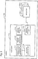
- Fig. 1 is a block diagram illustrating a configuration of a first exemplary embodiment of a message distribution system according to the present invention.
- a communication system includes terminals 100-1 to 100-n, a push server 200, and application servers 300-1 to 300-n.
- a push server 200 is exemplified in Fig. 1 , any number of push servers may be included.
- the terminals 100-1 to 100-n are, for example, communication terminals such as mobile phones.
- the push server 200 is communicatably connected to the application servers 300-1 to 300-n.
- the push server 200 is communicatably connected to the terminals 100-1 to 100-n via a mobile network, or a wireless LAN, and the Internet.
- the mobile network is, for example, a 3G network or an LTE network.
- the wireless LAN is, for example, a WiFi.
- Each terminal includes a push client 110 and applications 120-1 to 120-n.
- Fig. 2 is a block diagram illustrating a configuration of the first exemplary embodiment of the terminal.
- the push client 110 of each terminal 100 includes a terminal-status-notification transmission unit 111, a network (NW) status detection unit 112, a message-update-notification reception unit 113, a message reception unit 114, and a message notification unit 115.
- NW network
- the terminal-status-notification transmission unit 111 performs terminal status notification. Specifically, the terminal-status-notification transmission unit 111 notifies the push server 200 of information (hereinafter described as terminal status information) representing a terminal status.
- the terminal status information includes, for example, the IP address of the terminal 100.
- the NW status detection unit 112 detects a network status. Specifically, the NW status detection unit 112 detects, as a network status, a type of network to which the terminal 100 and the push server 200 are connected.
- the type of network is, for example, a wireless LAN, and a mobile network.
- the message-update-notification reception unit 113 receives a message update notification transmitted from the push server 200.
- the message reception unit 114 receives, from the push server 200, messages relating to a message update notification.
- the message notification unit 115 passes, to the applications 120-1 to 120-n, a message received from the push server 200.
- the applications 120-1 to 120-n are application programs running on the terminal 100.
- the applications 120-1 to 120-n are provided from, for example, a service provider or the like, and stored in a storage unit (not illustrated) provided in the terminal.
- the push client 110 is implemented by a CPU or the like provided in the terminal 100.
- the push server 200 is a server device which distributes a push message to the terminals.
- the push server 200 includes a control unit (not illustrated).
- the control unit is implemented by a CPU or the like provided in the push server 200.
- the expression “the control unit of the push server 200 processes” is described simply as “the push server 200 processes”.
- the application servers 300-1 to 300-n are server devices used by each service provider. Each of the application servers 300-1 to 300-n transmits, in response to an operation input by, e.g., a service provider, a message distribution request to the push server 200.
- the terminal uses a first communication method and a second communication method as a push method.
- the first communication method is a long polling method (hereinafter referred to simply as a long polling).
- the second communication method is a direct IP method (hereinafter referred to simply as a direct IP).
- the long polling is a method in which the push server blocks a response to an HTTP request (HTTP GET) from the terminal until a push message to distribute is generated. In other words, if there are no messages to distribute, the push server makes no response to the HTTP request until the push server receives a message distribution request from the application server.
- HTTP GET HTTP request
- the long polling utilizes an HTTP.
- a wireless LAN such as a WiFi
- a push message can be delivered to the terminal.
- the long polling can deliver a push message to the terminal.
- the long polling needs to always maintain a TCP session.
- the push server and the terminal need to periodically perform communication in order to maintain a TCP session. Therefore, when long polling is performed in a mobile network, congestion may occur. In addition, a server load may increase.
- the direct IP is a method in which the push server establishes, when distributing a message, a TCP session with the terminal and transmits a push message, utilizing the established TCP session.
- the terminal and the push server are located in different IP address spaces, respectively, so that the push server cannot establish a TCP connection to the terminal. Therefore, when the direct IP is utilized, it is necessary to locate the push server and the terminal inside the same NAT-device.
- a telecommunication firm can install a push server in a mobile network.
- the push server and the terminal can be installed inside the same NAT-device.
- the direct IP can be utilized via the mobile network by installing the push server in the mobile network by the carrier.
- the push server and the terminal are not located inside the same NAT-device, if a global IP address is assigned to the terminal, the push server can establish a TCP session with the terminal. Therefore, the direct IP can be utilized.
- the direct IP does not need to always maintain a TCP session. Therefore, even when the direct IP is utilized in the mobile network, the direct IP does not cause congestion.
- the terminal 100 properly uses the push methods according to the status of network. Specifically, in a case where the network is a wireless LAN, such as a WiFi, so that generally, the terminal is subordinated to the NAT-device thereof, the terminal 100 selects the long polling. In a case where the network is a mobile network including the terminal and the push server located inside the same NAT-device, the terminal 100 selects the direct IP.
- the network is a wireless LAN, such as a WiFi
- the terminal 100 selects the direct IP.
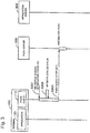
- Fig. 3 is a sequence diagram illustrating an operation when a terminal 100 selects the long polling as the push method.
- a single application 120 i.e., each of the applications 120-1 to 120-n
- any number of applications may run on the terminal 100.
- the single terminal 100 is exemplified.
- each terminal operates similarly to the terminal 100.
- the push client 110 of the terminal 100 detects that the status of the network changes (step S301). Specifically, the NW status detection unit 112 of the push client 110 receives, from an OS (Operating System) operating in the terminal 100, a notification (hereinafter described as a NW status change notification) indicating that the status of the network changes.
- OS Operating System
- the NW status detection unit 112 checks the status of the network, based on the NW status change notification (step S302). Specifically, the NW status detection unit 112 checks the type of the network connecting the terminal 100 and the push server 200. Here, the NW status detection unit 112 recognizes that the terminal 100 and the push server 200 are connected via the wireless LAN to each other.
- the message reception unit 114 selects the long polling as the push method. Then, the message reception unit 114 transmits a query request to the push server 200 in order to make a query (hereinafter described as a push query) about presence/absence of a push message to distribute. Specifically, the message reception unit 114 transmits an HTTP request (step S303).
- the push server 200 does not instantly respond to the HTTP request.
- the push server 200 blocks a response to the HTTP request until a push message to distribute to the push client 110 of the terminal 100 is generated. Incidentally, if there is a push message to distribute, the push server 200 instantly returns a response without blocking.
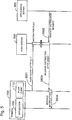
- Fig. 4 is a sequence diagram illustrating an operation when the terminal 100 selects the direct IP method as the push method.
- step S401 and that in step S402 are similar to that in the step S301 and that in the step S302, respectively. Therefore, a description of the processing in the step S401 and the processing in the step S402 is omitted.
- the NW status detection unit 112 recognizes that the terminal 100 and the push server 200 are connected via a mobile network to each other.
- the message reception unit 114 selects the direct IP as the push method.
- the message-update-notification reception unit 113 starts listening a TCP (step S403). Specifically, the message-update-notification reception unit 113 opens a TCP port so as to make the TCP port ready to receive a message update notification.
- the terminal-status-notification transmission unit 111 notifies the status of the terminal (step S404). Specifically, the terminal-status-notification transmission unit 111 transmits, to the push server 200, terminal status information including the IP address of the terminal and the port No. of the TCP port opened by the message-update-notification reception unit 113.
- the push client 110 of the terminal 100 waits for a TCP connection from the push server 200.
- the push client 110 waits for the push server 200 to establish a TCP session with the terminal 100.
- a TCP session between the push client 110 and the push server 200 is not established. Therefore, the push client 110 and the push server 200 do not need to periodically communicate with each other in order to maintain a TCP session.
- the push server 200 determines that the terminal 100 selects the long polling. Further, when receiving, terminal status information from the terminal-status-notification transmission unit 111 in the step S404, the push server 200 determines that the terminal 100 selects the direct IP.
- a result of selecting the push method is notified to the push server 200 by the terminal status notification or the push query.
- it is useful for example, that a path of a URL of the terminal status notification, and a path of the push query are set separately, and that then, the push server 200 determines which of the URLs is accessed.
- Fig. 5 is a sequence diagram illustrating a push-message distribution process according to the long polling method.
- the sequence diagram shown in Fig. 5 illustrates an operation of the message distribution system after the push query is made by the terminal 100.
- the push server 200 determines that the terminal 100 selects the long polling. At that time, the push server 200 waits for the generation of a push message to distribute, without responding instantly. In other words, the push server 200 is in a state of waiting for a push.
- the push server 200 When receiving a push-message distribution request from the application server 300 (step S502), the push server 200 transmits to the push client 110 a push message together with an HTTP response (HTTP 200OK) indicating that the HTTP request is normally processed (step S503).
- HTTP 200OK HTTP response
- the message notification unit 115 of the push client 110 passes the message received in the step S503 to a related application (step S504).
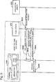
- Fig. 6 is a sequence diagram illustrating a push-message distribution process according to the direct IP method.
- the sequence diagram shown in Fig. 6 illustrates an operation of the message distribution system after the terminal 100 transmits the terminal status notification.
- the push server 200 When receiving a terminal status notification from the terminal 100, that is, when receiving terminal status information from the terminal 100, the push server 200 determines that the terminal 100 selects the direct IP. Then, when receiving a push-message distribution request from the application server 300 (step S601), the push server 200 performs a TCP connection to the client 110 (step S602). In the direct IP, this TCP connection is represented by a message update notification. In other words, the message-update-notification reception unit 113 detects the TCP connection. Thus, the message-update-notification reception unit 113 determines that a message update notification is performed.
- the message reception unit 114 uses this detection as a trigger and starts a message acquisition process. In other words, the message reception unit 114 transmits a message acquisition request as an HTTP request (step S603).
- the push server 200 transmits, to the push client 110, a push message together with an HTTP response indicating that the HTTP request is normally processed (step S604).
- the message notification unit 115 of the push client 110 passes, to a related application, the message received in the step S604 (step S605).
- the terminal determines the push method according to the status of the network.
- the processing load of the push server can be reduced, and, in addition, a push message can reliably be delivered to a push client in the terminal, regardless of the type of the network utilized by the terminal.
- the direct IP which does not need to always maintain a TCP session is selected when the terminal utilizes a mobile network, congestion of control signals in a mobile network can be suppressed from occurring.
- the long polling which allows to perform communication via a NAT-device/FW or communication via a proxy server is selected as the push method.
- the push method can be utilized as the push method. For example, if it is allowed that communication via a proxy server may not be performed, WebSocket and TCP unique communication can be utilized.
- the first communication method may be WebSocket or TCP unique communication.
- the WebSocket is a communication method for two-way communication on the TCP between a Web server and a browser.
- the WebSocket if a TCP session is once established, then, two-way communication between the terminal and the push server can be performed. However, according to the WebSocket, communication via a proxy server which does not support the WebSocket cannot be performed.
- the TCP unique communication is a communication method on the TCP, which is uniquely developed by a user or the like.
- the configuration of a terminal 100 according to the second exemplary embodiment is similar to the configuration of the terminal 100 according to the first exemplary embodiment. Therefore, a description of the configuration of the terminal 100 according to the second exemplary embodiment is omitted.
- the message distribution system which distributes a push message by the long polling and the direct IP has been exemplified.
- neither the long polling nor the direct IP cannot deliver a push message to the terminal.
- Such a case is, for example, that the terminal is in a no-communication state (sleep-state) for a long time, and that thus the IP address of the terminal is open.
- the push server 200 distributes a push message, utilizing an SMS (Short Message Service).
- SMS Short Message Service
- Fig. 7 is a sequence diagram illustrating a push-message distribution process according to the SMS.
- the push server 200 determines whether the push method selected by the terminal at a distribution destination can distribute a push message. In the present exemplary embodiment, the push server 200 performs a push-message distribution trial, and determines, based on a result of the distribution trial, whether a push message can be distributed (step S702).
- the push server 200 performs a push-message distribution trial according to the direct IP. However, if the terminal at the distribution destination selects the long polling as the push method, the push server 200 performs a push-message distribution trial according to the long polling.
- the terminal 100 may be in a sleep state for a long time, so that the IP address of the terminal 100 is open. In such a case, a push message cannot be distributed to the terminal 100.
- the push server 200 determines that the push method selected by the terminal at the distribution destination cannot perform push message distribution. Then, the push server 200 transmits to the push client 110 a notification indicating that there is a push message to distribute using the SMS (step S703). At that time, even if the IP address of the terminal 100 is open, the notification transmitted by the SMS is delivered to the terminal 100.
- the notification transmitted by the SMS is a message update notification. In other words, when receiving the message transmitted by the SMS, the message-update-notification reception unit 113 determines that there is a message update notification.
- the message reception unit 114 When the message-update-notification reception unit 113 of the push client 110 receives the notification transmitted according to the SMS, the message reception unit 114 starts a message acquisition process, using this notification as a trigger. At that time, the IP address of the terminal 100 is open. However, at a timing at which the terminal 100 tries to communicate with the push server 200, an IP address is assigned to the terminal 100. For example, a DHCP (Dynamic Host Configuration Protocol) server assigns an IP address to the terminal 100. Thus, a push message can be distributed to the terminal 100.
- DHCP Dynamic Host Configuration Protocol
- the message reception unit 114 transmits a message acquisition request to the push server 200 as an HTTP request (step S704).
- the push server 200 transmits a push message to the push client 110 together with an HTTP response indicating that the HTTP request is normally processed (step S705).
- the message notification unit 115 of the push client 110 passes the message received in the step S705 to an application provided in a distribution destination (step S706).
- the terminal when the terminal receives from the push server a notification which indicates that there is a push message to distribute, and which is transmitted using the SMS, the terminal transmits a message acquisition request to the push server. Therefore, even in the case where the push server using the long polling and the direct IP cannot deliver a push message to the terminal, if the push server transmits to the terminal a notification by the SMS, the terminal can acquire the push message based on the notification. Thus, for example, even in a case where the IP address of the terminal is open, a push message can reliably be distributed to the terminal.
- the case of using a notification transmitted by the SMS as a trigger has been exemplified.
- the terminal whose IP address is open, can be notified of information indicating that there is a push message to distribute, methods other than the SMS may be utilized.
- the configuration of a terminal 100 according to the third exemplary embodiment is similar to the configuration of the terminal 100 according to each of the first exemplary embodiment and the second exemplary embodiment. Therefore, a description of the configuration of the terminal 100 according to the third exemplary embodiment is omitted.
- the terminal-status-notification transmission unit 111 does not perform terminal status notification.
- Fig. 8 is a sequence diagram illustrating an operation of the third exemplary embodiment when the terminal 100 selects the direct IP method as the push method.
- step S801 that in step S802 and that in step S803 are similar to that in the step S401, that in the step S402 and that in the step S403, respectively. Therefore, a description of the processing in each of the steps S801 to S803 is omitted.
- the terminal-status-notification transmission unit 111 checks whether an IP address currently assigned to the terminal is the same as the IP address of the terminal at the time of performing the last terminal status notification (step S804).
- the terminal-status-notification transmission unit 111 does not perform terminal status notification (step S805). If the IP addresses are not the same as each other, the terminal-status-notification transmission unit 111 performs terminal status notification similarly to the processing in the step S404.
- the terminal selects the direct IP as the push method, if the IP address of the terminal is the same as the IP address thereof at the time of performing the last terminal status notification, the terminal does not perform terminal status notification. Consequently, the processing load of each of the terminal and the push server can be alleviated. Especially, in an environment in which the network status of the terminal is frequently changed, the processing load of each of the terminal and the push server can be alleviated.
- terminal status information is transmitted from the terminal to the push server every time where the network is switched from the WiFi to the mobile network. Accordingly, the processing load of each of the terminal and the push server may increase. However, according to the present exemplary embodiment, even in such an environment, the processing load of each of the terminal and the push server can be alleviated.
- Fig. 9 is a block diagram illustrating a minimum configuration of the terminal according to the present invention.
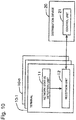
- Fig. 10 is a block diagram illustrating a minimum configuration of the message distribution system according to the present invention.
- the terminal 10 (equivalent to each of the terminals 100-1 to 100-n and the terminal illustrated in Fig. 2 ) includes:
- the network status detection unit 11 is equivalent to the NW status detection unit 112 of the push client 110 of the terminal 100 illustrated in Fig. 2 .
- the reception unit 12 is equivalent to a set of the terminal-status-notification transmission unit 111, the message-update-notification reception unit 113, and the message reception unit 114 of the push client 110 of the terminal 100 illustrated in Fig. 2 .
- a push message can reliably be delivered to the terminal, regardless of the type of network, while reducing the processing load of the distribution device.
- a terminal in which, if a first communication method is selected, a reception unit 12 transmits to a distribution device a query request querying presence/absence of a message to distribute, and in which, if a second communication method is selected, the reception unit 12 transmits to the distribution device a message acquisition request when a TCP connection with the distribution device is detected.
- a push message can be acquired from the distribution device according to the selected push method.
- the distribution device can recognize the IP address of the terminal, and the like, based on a terminal status notification.
- a TCP connection from the distribution device to the terminal can be performed.
- the notification of the terminal status information enables the distribution device to recognize that the terminal selects the direct IP as the push method.
- the notification by the SMS enables the terminal to recognize that there is a push message to distribute. Accordingly, even in such a case, the terminal can reliably acquire a push message.
- terminal status information can be suppressed from being transmitted when a network is switched to the mobile network. Accordingly, the processing load of each of the terminal and the push server can be more alleviated.
- a message distribution system illustrated in Fig. 10 is also disclosed.
- a message distribution system including terminals 10-1 to 10-n (equivalent to the terminals 100-1 to 100-n illustrated in Fig. 1 ) and a distribution device 20 (equivalent to the push server 200 illustrated in Fig. 1 ) which performs push-type message distribution to the terminals 10-1 to 10-n, each of the terminals 10-1 to 10-n including:
- a push message can reliably be delivered to the terminal, regardless of the type of network utilized by the terminal, without increasing the processing load of a distribution device.
- a message distribution system in which, if a network connecting a terminal and a distribution device 20 is a wireless LAN, a reception unit 12 determines that the terminal and the distribution device 20 are not located in a same IP address space, and in which, if the network is a mobile network, the reception unit 12 determines that the terminal and the distribution device 20 are located in the same IP address space.
- a message distribution system including terminals 10-1 to 10-n, and a distribution device 20 which performs push-type message distribution, each of the terminals 10-1 to 10-n including a network status detection unit 11 which detects a status of a network connecting the terminal and the distribution device 20, and a reception unit 12 which determines, based on a result of the detection, whether the terminal and the distribution device 20 are located in a same IP address space, selects, if the terminal and the distribution device 20 are not located in the same IP address space, a first communication method utilizing a pre-established TCP session, selects, if the terminal and the distribution device 20 are located in the same IP address space, a second communication method utilizing a TCP session between the distribution device 20 and the terminal, which is newly established by the distribution device 20 when a message is distributed, and receives a message from the distribution device 20 according to the selected communication method, the distribution device 20 including a control unit 21 which performs message distribution according to a communication-method selection result notified from the terminal.
- (Supplemental Note 2) A message distribution system according to the supplemental note 1, in which the reception unit 12 determines, if the network connecting the terminal and the distribution device 20 is a wireless LAN, that the terminal and the distribution device 20 is not located in the same IP address space, and also determines, if the network connecting the terminal and the distribution device 20 is a mobile network, that the terminal and the distribution device 20 is located in the same IP address space.
- FIG. 3 A message distribution system according to the supplemental note 1 or the supplemental note 2, in which, if the first communication method is selected, the reception unit 12 transmits to the distribution device 20 a query request querying presence/absence of a message to distribute, and in which, if the second communication method is selected, the reception unit 12 transmits to the distribution device 20 a message acquisition request when a TCP connection with the distribution device 20 is detected.
- a push message can be distributed from the distribution device to the terminal.
- FIG. 4 A message distribution system according to one of the supplemental note 1 to the supplemental note 3, in which the reception unit 12 notifies, when the second communication method is selected, the distribution device 20 of terminal status information including the IP address of the terminal, and in which, when a message is distributed, the control unit 21 establishes a TCP session with the terminal 10-1, ..., or 10-n, based on the terminal status information.
- the distribution device can recognize the IP address of the terminal, and the like, based on the terminal status notification.
- a TCP connection with the terminal from the distribution device can be performed.
- the notification of the terminal status information enables the distribution device to recognize that the terminal selects the direct IP as the push method.
- a message distribution system according to one of the supplemental note 1 to the supplemental note 4, in which when determining that message distribution by the first communication method or the second communication method cannot be performed, the control unit 21 transmits to the terminal 10-1, ... or 10-n a notification which indicates that there is a message to distribute and is transmitted by an SMS, and in which when detecting a notification transmitted by the SMS, the reception unit 12 transmits a message acquisition request to the distribution device 20.
- the distribution device transmits a notification by the SMS, so that the distribution device can make the terminal recognize that there is a push message to distribute. Accordingly, the distribution device can reliably transmit a push message to the terminal.
- terminal status information can be suppressed from being transmitted when the network is switched to the mobile network. Consequently, the processing load of each of the terminal and the push server can be more alleviated.
Landscapes
- Engineering & Computer Science (AREA)
- Computer Networks & Wireless Communication (AREA)
- Signal Processing (AREA)
- Computer Security & Cryptography (AREA)
- Mobile Radio Communication Systems (AREA)
- Telephonic Communication Services (AREA)
- Data Exchanges In Wide-Area Networks (AREA)
- Telephone Function (AREA)
Claims (7)
- Système de distribution de message comprenant :un terminal (10-1 à 10-n) ;un dispositif de distribution (20) qui est installé dans un réseau mobile et réalise une distribution de message de type pousser au terminal (10-1 à 10-n), dans lequel le terminal (10-1 à 10-n) comprend :une unité de détection de statut de réseau (11) qui est configurée pour recevoir en provenance d'un système d'exploitation, OS, configuré pour fonctionner dans le terminal (10-1 à 10-n), une notification indiquant que le statut du réseau change et est configurée en outre pour détecter un type d'un réseau connectant le terminal (10-1 à 10-n) et le dispositif de distribution (20) qui est configuré pour réaliser une distribution de message de type pousser ; etune unité de réception (12) qui est configurée pour déterminer, d'après un résultat de la détection, si le terminal (10-1 à 10-n) et le dispositif de distribution (20) sont situés dans un même espace adresse IP ;pour sélectionner, si le terminal (10-1 à 10-n) et le dispositif de distribution (20) ne sont pas situés dans le même espace adresse IP, une première méthode de communication utilisant une session TCP préétablie entre le terminal et le dispositif de distribution ;pour sélectionner, si le terminal (10-1 à 10-n) et le dispositif de distribution (20) sont situés dans le même espace adresse IP, une seconde méthode de communication utilisant une session TCP entre le terminal (10-1 à 10-n) et le dispositif de distribution (20) nouvellement établie par le dispositif de distribution (20) lorsqu'un message est distribué, etpour recevoir un message en provenance du dispositif de distribution (20) selon la méthode de communication sélectionnée,dans lequel le dispositif de distribution (20) comprend une unité de commande (21) qui réalise une distribution de message selon le résultat de sélection de méthode de communication notifié depuis le terminal (10-1 à 10-n),dans lequel l'unité de réception (12) est configurée pour déterminer, si le réseau connectant le terminal (10-1 à 10-n) et le dispositif de distribution (20) est un LAN sans fil, que le terminal (10-1 à 10-n) et le dispositif de distribution (20) ne sont pas situés dans le même espace adresse IP, et également pour déterminer, si le réseau est le réseau mobile, que le terminal (10-1 à 10-n) et le dispositif de distribution (20) sont situés dans le même espace adresse IP.
- Système selon la revendication 1, dans lequel, si la première méthode de communication est sélectionnée, l'unité de réception (12) est configurée pour transmettre au dispositif de distribution (20) une demande d'interrogation interrogeant la présence/l'absence d'un message à distribuer, et dans lequel, si la seconde méthode de communication est sélectionnée, l'unité de réception (12) est configurée pour transmettre au dispositif de distribution (20) une demande d'acquisition de message lorsqu'une connexion TCP avec le dispositif de distribution (20) est détectée.
- Système selon la revendication 1 ou 2, dans lequel l'unité de réception (12) est configurée pour notifier, lorsque la seconde méthode de communication est sélectionnée, au dispositif de distribution (20) des informations de statut de terminal incluant une adresse IP du terminal (10-1 à 10-n).
- Système selon l'une quelconque des revendications 1 à 3, dans lequel l'unité de réception (12) est configurée pour transmettre, lors de la détection d'une notification qui est transmise par SMS et qui indique qu'il y a un message à distribuer, une demande d'acquisition de message au dispositif de distribution (20).
- Système selon la revendication 3 ou 4, dans lequel, si une adresse IP actuelle du terminal (10-1 à 10-n) est la même qu'une adresse IP du terminal (10-1 à 10-n) à la dernière notification d'informations de statut de terminal, l'unité de réception (12) est configurée pour ne pas notifier au dispositif de distribution (20) les informations de statut de terminal.
- Procédé de distribution de message comprenant :la réception en provenance d'un système d'exploitation, OS, fonctionnant dans le terminal (10-1 à 10-n), d'une notification indiquant que le statut du réseau change ;la détection par le terminal (10-1 à 10-n) d'un type d'un réseau connectant le terminal (10-1 à 10-n) et un dispositif de distribution (20) qui est installé dans un réseau mobile et qui réalise une distribution de message de type pousser ;le fait de déterminer d'après un résultat de la détection, si le terminal (10-1 à 10-n) et le dispositif de distribution (20) sont situés dans un même espace adresse IP ;la sélection, si le terminal (10-1 à 10-n) et le dispositif de distribution (20) ne sont situés dans le même espace adresse IP, d'une première méthode de communication utilisant une session TCP préétablie entre le terminal et le dispositif de distribution ;la sélection, si le terminal (10-1 à 10-n) et le dispositif de distribution (20) sont situés dans le même espace adresse IP, d'une seconde méthode de communication utilisant une session TCP entre le terminal (10-1 à 10-n) et le dispositif de distribution (20) nouvellement établie par le dispositif de distribution (20) lorsqu'un message est distribué ;la réception, par le terminal, d'un message en provenance du dispositif de distribution (20) selon la méthode de communication sélectionnée ;la réalisation d'une distribution de message par le dispositif de distribution (20) selon le résultat de sélection de méthode de communication notifié par le terminal (10-1 à 10-n),dans lequel, si le réseau connectant le terminal (10-1 à 10-n) et le dispositif de distribution (20) est un LAN sans fil, il est déterminé que le terminal (10-1 à 10-n) et le dispositif de distribution (20) ne sont pas situés dans un même espace adresse IP, et dans lequel, si le réseau est le réseau mobile, il est déterminé que le terminal (10-1 à 10-n) et le dispositif de distribution (20) sont situés dans le même espace adresse IP.
- Programme de réception de message qui, lorsqu'il est exécuté par un ordinateur, amène l'ordinateur, qui est monté dans un terminal (10-1 à 10-n) capable de communiquer avec un dispositif de distribution (20) qui est installé dans un réseau mobile et réalise une distribution de message de type pousser, à effectuer :la réception par le terminal (10-1 à 10-n) en provenance d'un système d'exploitation, OS, configuré pour fonctionner dans le terminal (10-1 à 10-n), d'une notification indiquant que le statut du réseau change ;la détection d'un type d'un réseau connectant le terminal (10-1 à 10-n) et le dispositif de distribution (20) ; le fait de déterminer, d'après un résultat de la détection, si le terminal (10-1 à 10-n) et le dispositif de distribution (20) sont situés dans un même espace adresse IP ;la sélection, si le terminal (10-1 à 10-n) et le dispositif de distribution (20) ne sont pas situés dans le même espace adresse IP, d'une première méthode de communication utilisant une session TCP préétablie entre le terminal et le dispositif de distribution ;et la sélection, si le terminal (10-1 à 10-n) et le dispositif de distribution (20) sont situés dans le même espace adresse IP, d'une seconde méthode de communication utilisant une session TCP entre le terminal (10-1 à 10-n) et le dispositif de distribution (20) nouvellement établie par le dispositif de distribution (20) lorsqu'un message est distribué ;la réception d'un message en provenance du dispositif de distribution (20) selon la méthode de communication sélectionnée après notification au dispositif de distribution (20) du résultat de sélection de méthode de communication,dans lequel l'ordinateur est amené à effectuer le fait de déterminer, si le réseau connectant le terminal (10-1 à 10-n) et le dispositif de distribution (20) est un LAN sans fil, que le terminal (10-1 à 10-n) et le dispositif de distribution (20) ne sont pas situés dans un même espace adresse IP, et également le fait de déterminer, si le réseau est le réseau mobile, que le terminal (10-1 à 10-n) et le dispositif de distribution (20) sont situés dans le même espace adresse IP.
Applications Claiming Priority (2)
| Application Number | Priority Date | Filing Date | Title |
|---|---|---|---|
| JP2012230001 | 2012-10-17 | ||
| PCT/JP2013/005876 WO2014061220A1 (fr) | 2012-10-17 | 2013-10-02 | Terminal, système de distribution de message, procédé de distribution de message et programme de réception de message |
Publications (3)
| Publication Number | Publication Date |
|---|---|
| EP2911343A1 EP2911343A1 (fr) | 2015-08-26 |
| EP2911343A4 EP2911343A4 (fr) | 2016-06-29 |
| EP2911343B1 true EP2911343B1 (fr) | 2019-04-10 |
Family
ID=50487800
Family Applications (1)
| Application Number | Title | Priority Date | Filing Date |
|---|---|---|---|
| EP13846473.0A Active EP2911343B1 (fr) | 2012-10-17 | 2013-10-02 | Terminal, système de distribution de message, procédé de distribution de message et programme de réception de message |
Country Status (5)
| Country | Link |
|---|---|
| US (1) | US9866644B2 (fr) |
| EP (1) | EP2911343B1 (fr) |
| JP (1) | JP6241418B2 (fr) |
| CN (1) | CN104737499B (fr) |
| WO (1) | WO2014061220A1 (fr) |
Families Citing this family (3)
| Publication number | Priority date | Publication date | Assignee | Title |
|---|---|---|---|---|
| CN106658480A (zh) * | 2016-12-30 | 2017-05-10 | 上海顶竹通讯技术有限公司 | 一种终端互通的方法及系统 |
| CN110290228B (zh) * | 2019-06-03 | 2022-03-11 | 网宿科技股份有限公司 | 一种互联网协议ip地址分配方法及装置 |
| CN114244731B (zh) * | 2021-12-16 | 2024-02-27 | 湖南师范大学 | 终端屏幕亮屏检测方法及装置、服务器、电子设备 |
Family Cites Families (13)
| Publication number | Priority date | Publication date | Assignee | Title |
|---|---|---|---|---|
| JP2003032750A (ja) * | 2001-07-17 | 2003-01-31 | Nec Corp | 移動体端末への情報配信システムおよび情報配信方法 |
| US6985479B2 (en) * | 2002-03-04 | 2006-01-10 | Qualcomm Incorporated | Method and apparatus for processing internet protocol transmissions |
| FI20050067A (fi) | 2005-01-20 | 2006-07-21 | Pekka Rehtijaervi | Push-viestinnällä ohjattuja menetelmiä ja laitteita |
| US7617525B1 (en) | 2005-06-21 | 2009-11-10 | Alto Ventures, Inc. | System and method for connectionless client-server communications |
| JP2008085470A (ja) * | 2006-09-26 | 2008-04-10 | Fujitsu Ltd | Ipアプリケーションサービス提供システム |
| CN101466092A (zh) | 2007-12-18 | 2009-06-24 | 北京华星广视数码技术服务有限公司 | 一种在移动通信网络中实现推送的方法 |
| JP5564925B2 (ja) | 2009-12-14 | 2014-08-06 | 日本電気株式会社 | プッシュ型サービス実現方法、システム、装置、及びプログラム |
| KR101637601B1 (ko) * | 2010-10-15 | 2016-07-07 | 삼성전자주식회사 | 모바일 메시지 수신 장치 및 방법 |
| JP5248572B2 (ja) * | 2010-10-22 | 2013-07-31 | 株式会社オプティム | 通話のためのネットワークを選択するプログラム、携帯端末及び方法 |
| KR101345415B1 (ko) * | 2011-01-31 | 2014-01-29 | 주식회사 케이티 | 푸쉬 메시지 전송 방법, 상기 푸쉬 메시지를 수신하는 이동 단말 및 푸쉬 메시지 전송 시스템 |
| WO2012162965A1 (fr) * | 2011-08-26 | 2012-12-06 | 华为技术有限公司 | Procédé, système et élément de réseau pour « pousser » des données d'application |
| KR101287556B1 (ko) * | 2011-09-29 | 2013-07-23 | 주식회사 엘지씨엔에스 | 이동 단말기의 푸시 클라이언트 및 이를 이용한 프로바이더 변경방법 |
| CN102420827B (zh) * | 2011-12-13 | 2014-04-23 | 南京大学 | 面向智能移动平台的Web服务推送方法 |
-
2013
- 2013-10-02 JP JP2014541923A patent/JP6241418B2/ja active Active
- 2013-10-02 WO PCT/JP2013/005876 patent/WO2014061220A1/fr active Application Filing
- 2013-10-02 CN CN201380054088.9A patent/CN104737499B/zh active Active
- 2013-10-02 EP EP13846473.0A patent/EP2911343B1/fr active Active
- 2013-10-02 US US14/432,725 patent/US9866644B2/en active Active
Non-Patent Citations (1)
| Title |
|---|
| None * |
Also Published As
| Publication number | Publication date |
|---|---|
| US20150256637A1 (en) | 2015-09-10 |
| CN104737499A (zh) | 2015-06-24 |
| CN104737499B (zh) | 2018-05-04 |
| JPWO2014061220A1 (ja) | 2016-09-05 |
| US9866644B2 (en) | 2018-01-09 |
| EP2911343A1 (fr) | 2015-08-26 |
| JP6241418B2 (ja) | 2017-12-06 |
| EP2911343A4 (fr) | 2016-06-29 |
| WO2014061220A1 (fr) | 2014-04-24 |
Similar Documents
| Publication | Publication Date | Title |
|---|---|---|
| CN107645529B (zh) | 心跳包发送方法及装置 | |
| CN104429037B8 (zh) | 用于连接到通信设备的方法、设备及系统 | |
| EP3123667B1 (fr) | Procédé pour surveiller un état sous forme de présence et/ou d'absence d'une entité de réseau | |
| EP3352431B1 (fr) | Système, procédé, et appareil de traitement d'équilibrage de charge de réseau | |
| CN110012083B (zh) | 一种数据传输方法、服务器及数据传输装置 | |
| US9521059B2 (en) | Delivery device, communication system, load balancing method, and load balancing program | |
| US8175091B2 (en) | Communication system | |
| JP2012257288A (ja) | セッション接続の持続 | |
| US10666769B2 (en) | Network system and method for establishing data link by using relay node | |
| KR101473660B1 (ko) | 웹 기반 실시간 데이터 푸싱 방법 및 그 시스템 | |
| JP2008225644A (ja) | ゲートウェイ装置、ゲートウェイ装置の負荷分散方法及びゲートウェイ装置の負荷分散プログラム | |
| EP2911343B1 (fr) | Terminal, système de distribution de message, procédé de distribution de message et programme de réception de message | |
| US10075354B2 (en) | Identification of servers by common wide area network addresses | |
| WO2013159492A1 (fr) | Procédé et système pour le reporting et le téléchargement de données | |
| US10044590B2 (en) | Method of effective retaining of NAT channel service | |
| JP2014146876A (ja) | メッセージ配信システムおよびメッセージ配信方法 | |
| JP5661579B2 (ja) | 無線端末の消費電力を低減させる通信制御方法及びシステム | |
| KR20130047486A (ko) | 세션 릴레이 서버를 이용한 푸시 시스템 및 방법 | |
| US20120079553A1 (en) | Methods and Arrangements in a Telecommunication Network | |
| KR20150136330A (ko) | 푸쉬 메시지 수신 단말들 간 그룹 대화 제공 방법 및 시스템, 푸쉬 메시지 수신 단말들 간 정보 공유 장치 및 방법 | |
| JP2015154190A (ja) | ネットワークシステムおよびネットワーク管理方法 | |
| KR20130047487A (ko) | 복합 방식을 이용한 푸시 발송 시스템 및 방법 | |
| WO2012173609A1 (fr) | Mandataire de dispositif d'impression |
Legal Events
| Date | Code | Title | Description |
|---|---|---|---|
| PUAI | Public reference made under article 153(3) epc to a published international application that has entered the european phase |
Free format text: ORIGINAL CODE: 0009012 |
|
| 17P | Request for examination filed |
Effective date: 20150427 |
|
| AK | Designated contracting states |
Kind code of ref document: A1 Designated state(s): AL AT BE BG CH CY CZ DE DK EE ES FI FR GB GR HR HU IE IS IT LI LT LU LV MC MK MT NL NO PL PT RO RS SE SI SK SM TR |
|
| AX | Request for extension of the european patent |
Extension state: BA ME |
|
| DAX | Request for extension of the european patent (deleted) | ||
| RA4 | Supplementary search report drawn up and despatched (corrected) |
Effective date: 20160531 |
|
| RIC1 | Information provided on ipc code assigned before grant |
Ipc: H04L 29/06 20060101ALI20160524BHEP Ipc: H04L 29/08 20060101ALI20160524BHEP Ipc: H04W 48/18 20090101ALI20160524BHEP Ipc: H04W 28/02 20090101ALI20160524BHEP Ipc: H04M 3/00 20060101ALI20160524BHEP Ipc: H04W 84/12 20090101ALI20160524BHEP Ipc: H04L 12/58 20060101AFI20160524BHEP Ipc: H04M 1/733 20060101ALI20160524BHEP Ipc: H04L 29/12 20060101ALI20160524BHEP Ipc: H04W 80/06 20090101ALI20160524BHEP Ipc: H04W 4/12 20090101ALI20160524BHEP |
|
| STAA | Information on the status of an ep patent application or granted ep patent |
Free format text: STATUS: EXAMINATION IS IN PROGRESS |
|
| 17Q | First examination report despatched |
Effective date: 20180124 |
|
| GRAP | Despatch of communication of intention to grant a patent |
Free format text: ORIGINAL CODE: EPIDOSNIGR1 |
|
| STAA | Information on the status of an ep patent application or granted ep patent |
Free format text: STATUS: GRANT OF PATENT IS INTENDED |
|
| INTG | Intention to grant announced |
Effective date: 20181029 |
|
| GRAS | Grant fee paid |
Free format text: ORIGINAL CODE: EPIDOSNIGR3 |
|
| GRAA | (expected) grant |
Free format text: ORIGINAL CODE: 0009210 |
|
| STAA | Information on the status of an ep patent application or granted ep patent |
Free format text: STATUS: THE PATENT HAS BEEN GRANTED |
|
| AK | Designated contracting states |
Kind code of ref document: B1 Designated state(s): AL AT BE BG CH CY CZ DE DK EE ES FI FR GB GR HR HU IE IS IT LI LT LU LV MC MK MT NL NO PL PT RO RS SE SI SK SM TR |
|
| REG | Reference to a national code |
Ref country code: GB Ref legal event code: FG4D |
|
| REG | Reference to a national code |
Ref country code: CH Ref legal event code: EP Ref country code: AT Ref legal event code: REF Ref document number: 1120210 Country of ref document: AT Kind code of ref document: T Effective date: 20190415 |
|
| REG | Reference to a national code |
Ref country code: IE Ref legal event code: FG4D |
|
| REG | Reference to a national code |
Ref country code: DE Ref legal event code: R096 Ref document number: 602013053835 Country of ref document: DE |
|
| REG | Reference to a national code |
Ref country code: NL Ref legal event code: MP Effective date: 20190410 |
|
| REG | Reference to a national code |
Ref country code: LT Ref legal event code: MG4D |
|
| REG | Reference to a national code |
Ref country code: AT Ref legal event code: MK05 Ref document number: 1120210 Country of ref document: AT Kind code of ref document: T Effective date: 20190410 |
|
| PG25 | Lapsed in a contracting state [announced via postgrant information from national office to epo] |
Ref country code: NL Free format text: LAPSE BECAUSE OF FAILURE TO SUBMIT A TRANSLATION OF THE DESCRIPTION OR TO PAY THE FEE WITHIN THE PRESCRIBED TIME-LIMIT Effective date: 20190410 |
|
| PG25 | Lapsed in a contracting state [announced via postgrant information from national office to epo] |
Ref country code: HR Free format text: LAPSE BECAUSE OF FAILURE TO SUBMIT A TRANSLATION OF THE DESCRIPTION OR TO PAY THE FEE WITHIN THE PRESCRIBED TIME-LIMIT Effective date: 20190410 Ref country code: PT Free format text: LAPSE BECAUSE OF FAILURE TO SUBMIT A TRANSLATION OF THE DESCRIPTION OR TO PAY THE FEE WITHIN THE PRESCRIBED TIME-LIMIT Effective date: 20190910 Ref country code: SE Free format text: LAPSE BECAUSE OF FAILURE TO SUBMIT A TRANSLATION OF THE DESCRIPTION OR TO PAY THE FEE WITHIN THE PRESCRIBED TIME-LIMIT Effective date: 20190410 Ref country code: AL Free format text: LAPSE BECAUSE OF FAILURE TO SUBMIT A TRANSLATION OF THE DESCRIPTION OR TO PAY THE FEE WITHIN THE PRESCRIBED TIME-LIMIT Effective date: 20190410 Ref country code: FI Free format text: LAPSE BECAUSE OF FAILURE TO SUBMIT A TRANSLATION OF THE DESCRIPTION OR TO PAY THE FEE WITHIN THE PRESCRIBED TIME-LIMIT Effective date: 20190410 Ref country code: NO Free format text: LAPSE BECAUSE OF FAILURE TO SUBMIT A TRANSLATION OF THE DESCRIPTION OR TO PAY THE FEE WITHIN THE PRESCRIBED TIME-LIMIT Effective date: 20190710 Ref country code: ES Free format text: LAPSE BECAUSE OF FAILURE TO SUBMIT A TRANSLATION OF THE DESCRIPTION OR TO PAY THE FEE WITHIN THE PRESCRIBED TIME-LIMIT Effective date: 20190410 Ref country code: LT Free format text: LAPSE BECAUSE OF FAILURE TO SUBMIT A TRANSLATION OF THE DESCRIPTION OR TO PAY THE FEE WITHIN THE PRESCRIBED TIME-LIMIT Effective date: 20190410 |
|
| PG25 | Lapsed in a contracting state [announced via postgrant information from national office to epo] |
Ref country code: GR Free format text: LAPSE BECAUSE OF FAILURE TO SUBMIT A TRANSLATION OF THE DESCRIPTION OR TO PAY THE FEE WITHIN THE PRESCRIBED TIME-LIMIT Effective date: 20190711 Ref country code: BG Free format text: LAPSE BECAUSE OF FAILURE TO SUBMIT A TRANSLATION OF THE DESCRIPTION OR TO PAY THE FEE WITHIN THE PRESCRIBED TIME-LIMIT Effective date: 20190710 Ref country code: PL Free format text: LAPSE BECAUSE OF FAILURE TO SUBMIT A TRANSLATION OF THE DESCRIPTION OR TO PAY THE FEE WITHIN THE PRESCRIBED TIME-LIMIT Effective date: 20190410 Ref country code: RS Free format text: LAPSE BECAUSE OF FAILURE TO SUBMIT A TRANSLATION OF THE DESCRIPTION OR TO PAY THE FEE WITHIN THE PRESCRIBED TIME-LIMIT Effective date: 20190410 Ref country code: LV Free format text: LAPSE BECAUSE OF FAILURE TO SUBMIT A TRANSLATION OF THE DESCRIPTION OR TO PAY THE FEE WITHIN THE PRESCRIBED TIME-LIMIT Effective date: 20190410 |
|
| PG25 | Lapsed in a contracting state [announced via postgrant information from national office to epo] |
Ref country code: AT Free format text: LAPSE BECAUSE OF FAILURE TO SUBMIT A TRANSLATION OF THE DESCRIPTION OR TO PAY THE FEE WITHIN THE PRESCRIBED TIME-LIMIT Effective date: 20190410 Ref country code: IS Free format text: LAPSE BECAUSE OF FAILURE TO SUBMIT A TRANSLATION OF THE DESCRIPTION OR TO PAY THE FEE WITHIN THE PRESCRIBED TIME-LIMIT Effective date: 20190810 |
|
| REG | Reference to a national code |
Ref country code: DE Ref legal event code: R097 Ref document number: 602013053835 Country of ref document: DE |
|
| PG25 | Lapsed in a contracting state [announced via postgrant information from national office to epo] |
Ref country code: EE Free format text: LAPSE BECAUSE OF FAILURE TO SUBMIT A TRANSLATION OF THE DESCRIPTION OR TO PAY THE FEE WITHIN THE PRESCRIBED TIME-LIMIT Effective date: 20190410 Ref country code: DK Free format text: LAPSE BECAUSE OF FAILURE TO SUBMIT A TRANSLATION OF THE DESCRIPTION OR TO PAY THE FEE WITHIN THE PRESCRIBED TIME-LIMIT Effective date: 20190410 Ref country code: RO Free format text: LAPSE BECAUSE OF FAILURE TO SUBMIT A TRANSLATION OF THE DESCRIPTION OR TO PAY THE FEE WITHIN THE PRESCRIBED TIME-LIMIT Effective date: 20190410 Ref country code: CZ Free format text: LAPSE BECAUSE OF FAILURE TO SUBMIT A TRANSLATION OF THE DESCRIPTION OR TO PAY THE FEE WITHIN THE PRESCRIBED TIME-LIMIT Effective date: 20190410 Ref country code: SK Free format text: LAPSE BECAUSE OF FAILURE TO SUBMIT A TRANSLATION OF THE DESCRIPTION OR TO PAY THE FEE WITHIN THE PRESCRIBED TIME-LIMIT Effective date: 20190410 |
|
| PLBE | No opposition filed within time limit |
Free format text: ORIGINAL CODE: 0009261 |
|
| STAA | Information on the status of an ep patent application or granted ep patent |
Free format text: STATUS: NO OPPOSITION FILED WITHIN TIME LIMIT |
|
| PG25 | Lapsed in a contracting state [announced via postgrant information from national office to epo] |
Ref country code: IT Free format text: LAPSE BECAUSE OF FAILURE TO SUBMIT A TRANSLATION OF THE DESCRIPTION OR TO PAY THE FEE WITHIN THE PRESCRIBED TIME-LIMIT Effective date: 20190410 Ref country code: SM Free format text: LAPSE BECAUSE OF FAILURE TO SUBMIT A TRANSLATION OF THE DESCRIPTION OR TO PAY THE FEE WITHIN THE PRESCRIBED TIME-LIMIT Effective date: 20190410 |
|
| 26N | No opposition filed |
Effective date: 20200113 |
|
| PG25 | Lapsed in a contracting state [announced via postgrant information from national office to epo] |
Ref country code: TR Free format text: LAPSE BECAUSE OF FAILURE TO SUBMIT A TRANSLATION OF THE DESCRIPTION OR TO PAY THE FEE WITHIN THE PRESCRIBED TIME-LIMIT Effective date: 20190410 |
|
| PG25 | Lapsed in a contracting state [announced via postgrant information from national office to epo] |
Ref country code: SI Free format text: LAPSE BECAUSE OF FAILURE TO SUBMIT A TRANSLATION OF THE DESCRIPTION OR TO PAY THE FEE WITHIN THE PRESCRIBED TIME-LIMIT Effective date: 20190410 Ref country code: MC Free format text: LAPSE BECAUSE OF FAILURE TO SUBMIT A TRANSLATION OF THE DESCRIPTION OR TO PAY THE FEE WITHIN THE PRESCRIBED TIME-LIMIT Effective date: 20190410 |
|
| REG | Reference to a national code |
Ref country code: CH Ref legal event code: PL |
|
| PG25 | Lapsed in a contracting state [announced via postgrant information from national office to epo] |
Ref country code: LI Free format text: LAPSE BECAUSE OF NON-PAYMENT OF DUE FEES Effective date: 20191031 Ref country code: LU Free format text: LAPSE BECAUSE OF NON-PAYMENT OF DUE FEES Effective date: 20191002 Ref country code: CH Free format text: LAPSE BECAUSE OF NON-PAYMENT OF DUE FEES Effective date: 20191031 |
|
| REG | Reference to a national code |
Ref country code: BE Ref legal event code: MM Effective date: 20191031 |
|
| PG25 | Lapsed in a contracting state [announced via postgrant information from national office to epo] |
Ref country code: BE Free format text: LAPSE BECAUSE OF NON-PAYMENT OF DUE FEES Effective date: 20191031 |
|
| GBPC | Gb: european patent ceased through non-payment of renewal fee |
Effective date: 20191002 |
|
| PG25 | Lapsed in a contracting state [announced via postgrant information from national office to epo] |
Ref country code: GB Free format text: LAPSE BECAUSE OF NON-PAYMENT OF DUE FEES Effective date: 20191002 Ref country code: IE Free format text: LAPSE BECAUSE OF NON-PAYMENT OF DUE FEES Effective date: 20191002 |
|
| PG25 | Lapsed in a contracting state [announced via postgrant information from national office to epo] |
Ref country code: CY Free format text: LAPSE BECAUSE OF FAILURE TO SUBMIT A TRANSLATION OF THE DESCRIPTION OR TO PAY THE FEE WITHIN THE PRESCRIBED TIME-LIMIT Effective date: 20190410 |
|
| PG25 | Lapsed in a contracting state [announced via postgrant information from national office to epo] |
Ref country code: MT Free format text: LAPSE BECAUSE OF FAILURE TO SUBMIT A TRANSLATION OF THE DESCRIPTION OR TO PAY THE FEE WITHIN THE PRESCRIBED TIME-LIMIT Effective date: 20190410 Ref country code: HU Free format text: LAPSE BECAUSE OF FAILURE TO SUBMIT A TRANSLATION OF THE DESCRIPTION OR TO PAY THE FEE WITHIN THE PRESCRIBED TIME-LIMIT; INVALID AB INITIO Effective date: 20131002 |
|
| REG | Reference to a national code |
Ref country code: DE Ref legal event code: R079 Ref document number: 602013053835 Country of ref document: DE Free format text: PREVIOUS MAIN CLASS: H04L0012580000 Ipc: H04L0051000000 |
|
| PG25 | Lapsed in a contracting state [announced via postgrant information from national office to epo] |
Ref country code: MK Free format text: LAPSE BECAUSE OF FAILURE TO SUBMIT A TRANSLATION OF THE DESCRIPTION OR TO PAY THE FEE WITHIN THE PRESCRIBED TIME-LIMIT Effective date: 20190410 |
|
| PGFP | Annual fee paid to national office [announced via postgrant information from national office to epo] |
Ref country code: FR Payment date: 20231026 Year of fee payment: 11 Ref country code: DE Payment date: 20231020 Year of fee payment: 11 |