EP2911176A1 - Auxiliary switch with test button - Google Patents
Auxiliary switch with test button Download PDFInfo
- Publication number
- EP2911176A1 EP2911176A1 EP15150782.9A EP15150782A EP2911176A1 EP 2911176 A1 EP2911176 A1 EP 2911176A1 EP 15150782 A EP15150782 A EP 15150782A EP 2911176 A1 EP2911176 A1 EP 2911176A1
- Authority
- EP
- European Patent Office
- Prior art keywords
- slide
- switch
- circuit breaker
- auxiliary
- coupling
- Prior art date
- Legal status (The legal status is an assumption and is not a legal conclusion. Google has not performed a legal analysis and makes no representation as to the accuracy of the status listed.)
- Granted
Links
Images


Classifications
-
- H—ELECTRICITY
- H01—ELECTRIC ELEMENTS
- H01H—ELECTRIC SWITCHES; RELAYS; SELECTORS; EMERGENCY PROTECTIVE DEVICES
- H01H71/00—Details of the protective switches or relays covered by groups H01H73/00 - H01H83/00
- H01H71/10—Operating or release mechanisms
- H01H71/12—Automatic release mechanisms with or without manual release
- H01H71/128—Manual release or trip mechanisms, e.g. for test purposes
-
- H—ELECTRICITY
- H01—ELECTRIC ELEMENTS
- H01H—ELECTRIC SWITCHES; RELAYS; SELECTORS; EMERGENCY PROTECTIVE DEVICES
- H01H71/00—Details of the protective switches or relays covered by groups H01H73/00 - H01H83/00
- H01H71/10—Operating or release mechanisms
- H01H71/12—Automatic release mechanisms with or without manual release
- H01H71/46—Automatic release mechanisms with or without manual release having means for operating auxiliary contacts additional to the main contacts
- H01H71/462—Automatic release mechanisms with or without manual release having means for operating auxiliary contacts additional to the main contacts housed in a separate casing, juxtaposed to and having the same general contour as the main casing
-
- H—ELECTRICITY
- H01—ELECTRIC ELEMENTS
- H01H—ELECTRIC SWITCHES; RELAYS; SELECTORS; EMERGENCY PROTECTIVE DEVICES
- H01H9/00—Details of switching devices, not covered by groups H01H1/00 - H01H7/00
- H01H9/20—Interlocking, locking, or latching mechanisms
- H01H9/24—Interlocking, locking, or latching mechanisms for interlocking two or more parts of the mechanism for operating contacts
-
- H—ELECTRICITY
- H01—ELECTRIC ELEMENTS
- H01H—ELECTRIC SWITCHES; RELAYS; SELECTORS; EMERGENCY PROTECTIVE DEVICES
- H01H71/00—Details of the protective switches or relays covered by groups H01H73/00 - H01H83/00
- H01H71/02—Housings; Casings; Bases; Mountings
- H01H71/0264—Mountings or coverplates for complete assembled circuit breakers, e.g. snap mounting in panel
- H01H71/0271—Mounting several complete assembled circuit breakers together
- H01H2071/0278—Mounting several complete assembled circuit breakers together with at least one of juxtaposed casings dedicated to an auxiliary device, e.g. for undervoltage or shunt trip
Definitions
- the invention relates to an auxiliary switch for attachment to a circuit breaker, with an auxiliary contact apparatus with at least one auxiliary contact point.
- An auxiliary switch is used to open and / or close auxiliary circuits, by means of the auxiliary circuits of the switching state of the main contacts of a circuit breaker to which the auxiliary switch is attached, is transmitted uniquely.
- the auxiliary circuit is galvanically isolated from the main circuit.
- a circuit breaker may for example be designed as a selective main line circuit breaker.
- a selective main circuit breaker also referred to as SH switch for short, is used in an electricity meter system in front of the meter in the meter box of a domestic electrical installation installation, and thus in front of the installation distributor of a domestic installation. Its purpose is the selective shutdown of the power supply to all downstream circuits in the event of a short circuit in one of the downstream circuits. Selective shutdown means time-delayed shutdown.
- An SH-switch is provided with a time delay, whereby it does not switch off immediately in a short-circuit current in one of the downstream circuits, but only after a certain delay time.
- the circuit breaker of that subordinate circuit in which the short circuit has occurred has the chance to shut off the short circuit itself. If this succeeds, the SH switch does not switch and the supply of the remaining, non-faulty circuits remains unaffected. Only if the short-circuit current is still present after the end of the delay time does the SH switch interrupt the power supply to the counter and thus to all downstream circuits.
- the selectivity is achieved by first bypassing the current when a short-circuit current occurs by opening a so-called main contact point in the current path from the main current path to a parallel secondary current path and limiting it by a so-called selective resistance. Between the input and output terminals now flows a limited short-circuit current.
- a time-delayed interruption element usually a bimetallic strip, often called a selective bimetal.
- a trigger with a long delay which in a known manner upon occurrence of a long time applied overload current in the main current path so farellegt that also a coupling with the trigger element of the switching mechanism is effected, causing in the latch released the latch and thereby also the secondary contact is permanently opened, which then the current path between the input and output terminals is completely interrupted.
- a selective main circuit breaker thus has a contactor with two contact points, a main contact point and a secondary contact point.
- Such a SH switch is for example from the DE 102 61 994 A1 known and its functional scheme described there.
- auxiliary switch which is suitable for mounting on a selective main circuit breaker to display and transmit the switching state of the selective main line circuit breaker, it is not necessary to be able to switch the auxiliary switch itself, it should only map the switching position of the selective main line circuit breaker.
- An auxiliary switch for attachment to a circuit breaker having a contactor with two contact points shows the EP 0949646 A2 .
- the EP 0946646 A2 shown derailleur includes a complicated lever assembly with four different levers, which are each acted upon by a spring. This makes the construction of the auxiliary switch complicated, too complicated to use with a selective main circuit breaker.
- the auxiliary switch is formed with a slider assembly having a circuit breaker side coupling point for coupling with a contactor of the circuit breaker and a HilfssWalletapparat discoverede coupling point has to be coupled to the Hilfs.apparat, wherein the slide assembly is formed with an outer slide having an outer slide switch-on position and an outer slide And a slider-coupling arrangement for coupling the outer slide with the inner slide, the circuit breaker side coupling point on the outer slide and the auxiliary contact side coupling point on the inner slide are formed, wherein the auxiliary switch is formed with a test button which is coupled to the inner slider for simulating a switch-off position of the contact apparatus of the circuit breaker when the circuit breaker is switched on, wherein, when the outer slide is held in its outer slide switch-on position, the inner slide is displaced under the action of the test button from the inner slide switch-on in the inner slide switch-off to form a the inner slide towards the mecanicschieber- on position towards acting restoring force.
- a two-slide system which includes an outer slide with coupling to the Selective main circuit breaker and an inner slide for moving the contacts and simulation of the switching position.
- the two-slider system is a very simple and easy to implement and install construction.
- the function of the test button realized according to the invention. In the test function, when the Selective Main Circuit Breaker is activated, by pressing the auxiliary switch test button, it is possible to simulate the disconnection of the Selective Main Circuit Breaker without activating the Selective Main Circuit Breaker itself.
- the auxiliary contact apparatus is formed with two changeover contacts, and on the inner slide two auxiliary contact point coupling points are formed.
- the auxiliary switch is formed in an advantageous embodiment with two changeover contacts, which indicate the contact position of the Selective main switch.
- the auxiliary switch can be coupled in an advantageous embodiment via a coupling axis with a pull tab of the switching mechanism of the Selective main circuit breaker.
- the slider-coupling arrangement comprises a spring element mounted between the outer and the inner slider, which generates the restoring force.
- the inner slide In the on position of the Selective main circuit breaker can be moved upwards pressing the test button, the inner slide, wherein he compresses the spring element and brings the two contacts of the auxiliary contact apparatus in the other contact position. After releasing the test button brings the restoring spring force of the spring element, the inner slide back to its original position. The restoring spring force of the spring element is greater than the switching force of the two contacts.
- the test button is with a Switch position display formed.
- the test button is formed with an actuating groove for a tool.
- the outer slide and the inner slide are each formed with a longitudinally extended body, which are arranged and held longitudinally displaceable against each other in a longitudinally displaceable manner.
- the outer slide and the inner slide with the slide coupling arrangement can be executed as a preassembled module and used in the auxiliary switch.
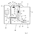
- FIG. 1 schematically shows an auxiliary switch 10 in a first embodiment.
- the auxiliary switch 10 has an insulating housing 11, with a front side 12, one of the front side opposite mounting side 13 and a right and a left narrow side 14, 15. Inside an auxiliary contact point 16 is shown, in the form of a changeover contact.
- the auxiliary contact point 16 forms the contact apparatus of the auxiliary switch 10.
- the changeover contact is formed with a first and a second fixed contact piece 17, 18 and with a movable contact piece 19 which is located at the end of a pivotally mounted contact carrier 20.
- FIGS. 1 to 3 is shown purely by way of example only one formed as a changeover contact auxiliary contact point, just as it could be two or more auxiliary contact points.
- the auxiliary switch is to indicate with the auxiliary contact point 16, the contact position of a selective main line circuit breaker 21, to which it is attached.
- the selective main circuit breaker 21 is in the Figures 1-3 also only very schematically and exemplified.
- the selective circuit breaker 21 has a contactor, not shown here, comprising a main contact point and a sub contact point.
- the contact apparatus of the selective main circuit breaker 21 is switched by means of the switching mechanism 23.
- the rear derailleur 23 has a pull tab (not shown).
- the auxiliary switch 10 is shown as queued with its narrow side 15 to a narrow side of the selective main circuit breaker 21. This is an abstraction chosen for the purpose of reduction to the essential. In real combinations of a selective main circuit breaker and an auxiliary switch, the two devices are almost always strung together on their broadsides.
- the auxiliary switch 10 is coupled via a coupling axis 24 with the pull tab of the derailleur 23 of the selective main line circuit breaker 21. Since the derailleur 23 cooperates with the contactor of the selective main circuit breaker 21, thus the auxiliary switch 10 is also coupled to the contactor of the selective main line circuit breaker.
- the coupling is indicated by a dashed operative connection line 25.
- the attachment point of the coupling axis 24 on the outer slide 29 functionally represents a circuit breaker side coupling point of the slider assembly 28. A real design is familiar to the expert and will not be explained in detail here.
- the coupling axis 24 projects laterally out of the auxiliary switch 10 at an elongate passage opening 26.
- the housing 22 of the selective main line circuit breaker 21 has correspondingly a receiving opening 27th
- the pull tab of its derailleur 23 moves in the direction of the double arrow P1, either from bottom to top or from top to bottom, and accordingly also the coupling axis 24 in the direction of the double arrow P1, either of down to the top or from top to bottom, taken.
- the switching position is shown in which the selective main circuit breaker 21 is turned on.
- the coupling axis 24 is located at the lower end of the elongated passage opening 26th
- the changeover switch of the auxiliary contact point 16 is located in FIG. 1 in a first stable position, that is a position in which the movable contact piece 19 is in contact with the first fixed contact piece 17. This is also shown as an example only. This position of the formed as a changeover switch auxiliary contact point 16 thus forms the switching position "on" of the selective main line circuit breaker 21 from.
- the auxiliary switch 10 is formed with a two-slider system 28.
- the two-slider system 28 includes an outer slide 29 and an inner slide 30. Both are elongate members. They can consist of a plastic material and be manufactured by injection molding. On the outer slide 29, the coupling axis 24 is attached. The outer slide 29 is the portion of the two-slider system 28, which implements the coupling to the selective main line circuit breaker 21 and is coupled to the switching mechanism of the selective main line circuit breaker 21.
- the inner slide 30 is mechanically coupled to the contact carrier 20 of the changeover switch 16, shown schematically and abstracted by the dashed operative connecting line 31.
- the point of action of the operative connection 31 on the inner slide 30 is the auxiliary contact device side coupling point of the slide assembly 28th
- the outer slide 29 and the inner slide 30 are designed and guided so that they can slide .parallel to each other sliding, indicated by the parallel double arrows P2 and P3.
- a cylindrical spring 34 is mounted between the outer slide 29 and the inner slide 30. This is supported at the upper end of the outer slide on a third web 35 and on a vebundenen with the inner slide 30 fourth web 36 which is disposed below the third web 35 from. At the transition from the closed position of the outer slide 29 to Fig. 1 to the switch-off position of the outer slide after FIG. 2 does not change the distance between the third web 35 and the fourth web 36, the cylinder spring 34 is not compressed.
- the first and second web 32, 33 and the cylinder spring 34 with the third and fourth web 35, 36 forms an example here together a slide coupling arrangement.
- the coupling with the contact carrier along the operative connection 31 ensures that the contact carrier 20 is made from its first stable position in which the contact between the movable contact piece 19 and the first fixed contact piece 17 is made, in its second stable position in which the contact between the movable contact piece 19 and the second fixed contact piece 18 made passes.
- the inner slider 30 is coupled at its upper free end with a test button 37.
- the test button 37 has the shape of a double-armed lever, which is fixed to the housing at a bearing 38 and pivotally mounted.
- a first arm 39 of the test button 37 is formed at its free end with a slot 40.
- the inner slider 30 carries at its upper free end a cam-like protruding pin 41, which is guided in the slot 40 in engagement standing.
- the second arm 42 of the test button 37 has a control and display surface 43.
- the test button 37 is mounted near the front 12.
- the control and display surface 43 is visible and operable through a recess 44 in the front side 12, it is more or less flush with the front side 12 from.
- a marker 45 is attached on the control and display surface 43. This is clearly visible from the outside through the recess 44 and serves as a position indicator of the test button.
- FIG. 2 shows this position.
- the marker 45 is now pivoted into the housing interior. Depending on how the marker is executed, it will no longer be visible or another part of the marker, which may be in a different color, will be visible. In any event, pivoting the second arm 42 outwardly indicates that the auxiliary contact point 16 is in its second stable position in which contact between the movable contact piece 19 and the second fixed contact piece 18 is established.
- FIG. 3 is the test function illustrates how it can be realized according to the invention with the test button in the on state of the selective main circuit breaker.
- the outer slide 29 is held on the coupling axis 24 down in the closed position of the auxiliary switch. If you press now from the outside on the control and display surface 43 of the test button 37, then you swung the test button 37 forcibly counterclockwise. Due to the coupling of the pin 41 with the slot 40, the first arm 39 of the test button 37 pulls the inner slider 30 upward, the auxiliary contact point 16 goes into the off position, as in connection with FIG. 2 described above.
- a switch-off in the auxiliary switch 10 was simulated when the selective main circuit breaker was switched on. This can be done for verification purposes.
- a fixed housing stop 46 limits the maximum pivoting range of the test button, which is advantageous in order to avoid damage to the described mechanism due to further pivoting.
- test button 37 can be done by hand, with the finger, or by means of a tool.
- an actuation groove can still be provided on the operating and display surface 43, as an attachment point for an actuation tool, for example a screwdriver.
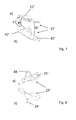
- FIGS. 4 to 6 show a further possible concrete embodiment of an auxiliary switch 10 'according to the invention.
- the same or similar and equivalent components or elements are denoted by the same reference numerals as in the FIGS. 1 to 3 , supplemented by a superscript comma. It corresponds to the in the FIG. 4 shown situation of those according to FIG. 1 .
- FIG. 5 corresponds to FIG. 2 and FIG. 6 corresponds to FIG. 3 ,
- the two-slider system 28 ' is arranged in the interior of the auxiliary switch housing extending obliquely from bottom left to top right.
- one auxiliary contact point 16 ' is to the right of the two-slider system 28', and the second auxiliary contact point 16 "is to the left of the two-slider system 28 '.
- Each of the contact carriers 20 ', 20 is constructed in the structure of a fixed to a pivot axis and pivotally mounted double-armed lever, with a longer arm, which carries the movable contact piece 19', 19", and with a shorter second arm, which at active junctions 31st ', 31 "is non-positively coupled to the inner slide 30'.
- the outer slide 29 ' carries an approximately triangular shaped Anformung 48 which is mounted projecting to the left.
- the free end of this Anformung forms the circuit breaker side coupling point of the two-slider system 28 '.
- the coupling axis 24 ' is attached. It protrudes here, as is customary, projecting perpendicular to the broad side of the housing, in the representation of the FIGS. 4 to 6 this is perpendicular to the drawing plane. It can be seen running as a slot hole 26 '.
- test button 37' At the control and display surface 43 'of the test button 37' here is still a groove 47 attached as attachment point for an operating tool, such as a screwdriver.
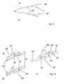
- the test key 37 ' is more specifically in the FIG. 7 shown.
- the outer slide 29 ' is in detail in the FIG. 8 shown, and the inner slide 30 'in the FIG. 9 ,
- the FIG. 10 shows how the inner slider 30 'inserted into the outer slide 29' and then the cylinder spring 34 'is inserted.
- the outer slide 29 ' has a trough-shaped edge boundary with an overlapping guide strip.
- the inner slider 30 ' is inserted and moved so far until the cylinder spring 34' in the receiving space between the two webs 35 'on the outer slide 29' and 36 'on the inner slider 30' can be used.
- the so captive preassembled module can then be easily inserted into the auxiliary switch at the intended location.
- auxiliary switch 24 ' coupling axis 10 ' auxiliary switch 25 Operatively connected line 11 Insulated 26 Through opening 11 ' Insulated 26 ' Through opening 12 front 27 receiving opening 12 ' front 28
- Auxiliary contact point 31 Operatively connected line 16 ' first auxiliary contact point 31 ' Active junction 16 " second auxiliary contact point 31 " Active junction 17 first fixed contact piece 32 first jetty 17 ' first fixed contact piece 33 second bridge 17 " first fixed contact piece 34 cylinder spring 18 second fixed contact piece 35 third jetty 18 ' second fixed contact piece 35 ' third jetty 18 " second fixed contact piece 36 fourth bridge 19 movable contact piece 36 ' fourth bridge 19 ' movable contact piece 37 Test button 19 " movable contact piece 37 ' Test button
Abstract
Die Erfindung betrifft einen Hilfsschalter (10) zum Anbau an einen Leitungsschutzschalter (21), mit einem Hilfskontaktapparat mit wenigstens einer Hilfskontaktstelle (16). Der Hilfsschalter (10) ist mit einer Schieberanordnung (28) gebildet, die eine leitungsschutzschalterseitige Koppelstelle hat zur Kopplung mit einem Kontaktapparat des Leitungsschutzschalters (21) und eine hilfskontaktapparatseitige Koppelstelle hat zur Kopplung mit dem Hilfskontaktapparat. Die Schieberanordnung (28) ist mit einem Außenschieber (29) gebildet, der eine Außenschieber-Einschaltstellung und eine Außenschieber-Ausschaltstellung einnehmen kann, und mit einem Innenschieber (30), der eine Innenschieber-Einschaltstellung und eine Innenschieber-Ausschaltstellung einnehmen kann, und einer Schieber-Koppelanordnung zur Kopplung des Außenschiebers (29) mit dem Innenschieber (30), wobei die leitungsschutzschalterseitige Koppelstelle an dem Außenschieber und die hilfskontaktapparatseitige Koppelstelle an dem Innenschieber (30) gebildet sind. Der Hilfsschalter (10) ist mit einem Test-Taster (37) gebildet, der gekoppelt ist mit dem Innenschieber (30) zur Simulation einer Ausschaltstellung des Kontaktapparates des Leitungsschutzschalters (21) bei eingeschaltetem Leitungsschutzschalter (21). Bei in seiner Außenschieber-Einschaltstellung festgehaltenem Außenschieber (29) ist der Innenschieber (30) unter Einwirkung des Test-Tasters (37) aus der Innenschieber-Einschaltstellung in die Innenschieber-Ausschaltstellung verschieblich unter Ausbildung einer den Innenschieber (30) in Richtung auf die Innenschieber-Einschaltstellung hin beaufschlagenden rückstellenden Kraft.The invention relates to an auxiliary switch (10) for mounting on a circuit breaker (21), with an auxiliary contact apparatus having at least one auxiliary contact point (16). The auxiliary switch (10) is formed with a slider assembly (28) having a circuit breaker side coupling point for coupling to a contactor of the circuit breaker (21) and a Hilfsskontaktatseitseit coupling point has to be coupled to the auxiliary contact apparatus. The slider assembly (28) is formed with an outer slider (29) which can assume an outer slider switch-on position and an outer slide switch-off position, and with an inner slider (30), which can take an inner slider switch-on position and an inner slide switch-off, and a Slider coupling arrangement for coupling the outer slide (29) with the inner slide (30), wherein the circuit breaker side coupling point on the outer slide and the auxiliary contact side coupling point on the inner slide (30) are formed. The auxiliary switch (10) is formed with a test button (37) which is coupled to the inner slide (30) for simulating a switch-off position of the contact apparatus of the circuit breaker (21) when the circuit breaker (21). When held in its outer slide switch-on position outer slide (29) of the inner slide (30) under the action of the test button (37) from the inner slide switch-on in the inner slide switch-off position to form a the inner slide (30) in the direction of the inner slide Switch-on position acting on restoring force.
Description
Die Erfindung betrifft einen Hilfsschalter zum Anbau an einen Leitungsschutzschalter, mit einem Hilfskontaktapparat mit wenigstens einer Hilfskontaktstelle.The invention relates to an auxiliary switch for attachment to a circuit breaker, with an auxiliary contact apparatus with at least one auxiliary contact point.
Ein Hilfsschalter dient zum Öffnen und/oder Schließen von Hilfsstromkreisen, wobei mittels der Hilfsstromkreise der Schaltzustand der Hauptkontakte eines Leitungsschutzschalters, an den der Hilfsschalter angebaut ist, eindeutig übertragen wird. Der Hilfsstromkreis ist dabei vom Hauptstromkreis galvanisch getrennt.An auxiliary switch is used to open and / or close auxiliary circuits, by means of the auxiliary circuits of the switching state of the main contacts of a circuit breaker to which the auxiliary switch is attached, is transmitted uniquely. The auxiliary circuit is galvanically isolated from the main circuit.
Ein Leitungsschutzschalter kann beispielsweise auch als selektiver Hauptleitungsschutzschalter ausgebildet sein. Ein selektiver Hauptleitungsschutzschalter, auch kurz als SH-Schalter bezeichnet, wird in einem Stromzählersystem vor dem Zähler im Zählerkasten einer elektrischen Hausinstallationsanlage eingesetzt, und damit auch vor dem Installationsverteiler einer Hausinstallationsanlage. Sein Zweck ist das selektive Abschalten der Stromzufuhr zu allen ihm nachgeordneten Stromkreisen bei Auftreten eines Kurzschlusses in einem der nachgeordneten Stromkreise. Selektives Abschalten bedeutet dabei zeitverzögertes Abschalten. Ein SH-Schalter ist mit einer Zeitverzögerung versehen, wodurch er bei einem Kurzschlussstrom in einem der nachgeordneten Stromkreise nicht sofort abschaltet, sondern erst nach einer gewissen Verzögerungszeit. Innerhalb der Verzögerungszeit hat der Schutzschalter desjenigen nachgeordneten Stromkreises, in dem der Kurzschluss aufgetreten ist, die Chance, den Kurzschluss selbst abzuschalten. Gelingt dies, so schaltet der SH-Schalter nicht, und die Versorgung der übrigen, nicht gestörten Stromkreise bleibt unbeeinflusst. Nur wenn der Kurzschlussstrom nach Ende der Verzögerungszeit immer noch anliegt, unterbricht der SH-Schalter die Stromzufuhr zum Zähler und damit zu allen nachgeordneten Stromkreisen.A circuit breaker may for example be designed as a selective main line circuit breaker. A selective main circuit breaker, also referred to as SH switch for short, is used in an electricity meter system in front of the meter in the meter box of a domestic electrical installation installation, and thus in front of the installation distributor of a domestic installation. Its purpose is the selective shutdown of the power supply to all downstream circuits in the event of a short circuit in one of the downstream circuits. Selective shutdown means time-delayed shutdown. An SH-switch is provided with a time delay, whereby it does not switch off immediately in a short-circuit current in one of the downstream circuits, but only after a certain delay time. Within the delay time, the circuit breaker of that subordinate circuit in which the short circuit has occurred has the chance to shut off the short circuit itself. If this succeeds, the SH switch does not switch and the supply of the remaining, non-faulty circuits remains unaffected. Only if the short-circuit current is still present after the end of the delay time does the SH switch interrupt the power supply to the counter and thus to all downstream circuits.
Bei einem spannungsunabhängigen SH-Schalter wird die Selektivität dadurch erreicht, dass der Strom bei Auftreten eines Kurzschlussstromes zunächst durch die Öffnung einer sogenannten Hauptkontaktstelle im Strompfad vom Hauptstrompfad auf einen parallelen Nebenstrompfad umgeleitet und dabei durch einen sogenannten Selektivwiderstand begrenzt wird. Zwischen den Ein- und Ausgangsklemmen fließt jetzt ein begrenzter Kurzschlussstrom. In dem Nebenstrompfad befindet sich ein zeitverzögertes Unterbrechungselement, meistens ein Thermobimetall, oft auch Selektiv-Bimetall genannt. Nach Ablauf der Verzögerungszeit biegt dieses sich so weit aus, dass eine Kopplung mit einem Auslöseelement eines Schaltschlosses bewirkt wird, wodurch in dem Schaltschloss eine Verklinkung gelöst und dadurch eine sog. Nebenkontaktstelle dauerhaft geöffnet wird, wodurch dann der Strompfad zwischen den Ein- und Ausgangsklemmen vollständig unterbrochen ist.In the case of a voltage-independent SH switch, the selectivity is achieved by first bypassing the current when a short-circuit current occurs by opening a so-called main contact point in the current path from the main current path to a parallel secondary current path and limiting it by a so-called selective resistance. Between the input and output terminals now flows a limited short-circuit current. In the secondary flow path is a time-delayed interruption element, usually a bimetallic strip, often called a selective bimetal. After the delay time, this bends so far that a coupling with a trigger element of a switching mechanism is effected, thereby releasing a latch in the switching mechanism, thereby permanently opening a so-called secondary contact point, thereby completely completing the current path between the input and output terminals is interrupted.
Daneben befindet sich im Hauptstrompfad noch das Haupt-Bimetall, ein Auslöser mit langer Verzögerung, der in bekannter Weise bei Auftreten eines über längere Zeit anliegenden Überlaststromes im Hauptstrompfad sich so weit ausbiegt, dass ebenfalls eine Kopplung mit dem Auslöseelement des Schaltschlosses bewirkt wird, wodurch in dem Schaltschloss die Verklinkung gelöst und dadurch ebenfalls die Nebenkontaktstelle dauerhaft geöffnet wird, wodurch dann der Strompfad zwischen den Ein- und Ausgangsklemmen vollständig unterbrochen ist.In addition, in the main current path is still the main bimetal, a trigger with a long delay, which in a known manner upon occurrence of a long time applied overload current in the main current path so far auszubiegt that also a coupling with the trigger element of the switching mechanism is effected, causing in the latch released the latch and thereby also the secondary contact is permanently opened, which then the current path between the input and output terminals is completely interrupted.
Ein selektiver Hauptleitungsschutzschalter hat also einen Kontaktapparat mit zwei Kontaktstellen, einer Hauptkontaktstelle und einer Nebenkontaktstelle.A selective main circuit breaker thus has a contactor with two contact points, a main contact point and a secondary contact point.
Ein solcher SH-Schalter ist beispielsweise aus der
Bei einem Hilfsschalter, der zum Anbau an einen selektiven Hauptleitungsschutzschalter geeignet ist, um den Schaltzustand des selektiven Hauptleitungsschutzschalters anzuzeigen und zu übertragen, ist es nicht erforderlich, den Hilfsschalter selbst auch schalten zu können, er soll lediglich die Schaltstellung des selektiven Hauptleitungsschutzschalters abbilden.In an auxiliary switch, which is suitable for mounting on a selective main circuit breaker to display and transmit the switching state of the selective main line circuit breaker, it is not necessary to be able to switch the auxiliary switch itself, it should only map the switching position of the selective main line circuit breaker.
Einen Hilfsschalter zum Anbau an einen Leitungsschutzschalter, der einen Kontaktapparat mit zwei Kontaktstellen hat, zeigt die
Es ist daher die der vorliegenden Erfindung zugrunde liegende Aufgabe, einen Hilfsschalter zu schaffen, der einfach aufgebaut ist, einfach zu montieren ist und ohne unnötige Zusatzfunktionen geeignet ist, die Schaltstellung eines selektiven Hauptleitungsschutzschalters anzuzeigen, und der dabei mit einer Testfunktion ausgestattet ist, die es erlaubt, bei eingeschaltetem selektiven Hauptleitungsschutzschalter im Hilfsschalter das Ausschalten des selektiven Hauptleitungsschutzschalters zu simulieren.It is therefore an object of the present invention to provide an auxiliary switch which is simple in construction, easy to assemble and, without unnecessary additional functions, is capable of indicating the switching position of a selective main line circuit breaker and which is equipped with a test function which provides it allows to simulate the deactivation of the selective main line circuit breaker when the selective main circuit breaker in the auxiliary switch.
Die Aufgabe wird gelöst durch einen Hilfsschalter gemäß Anspruch 1.The object is achieved by an auxiliary switch according to claim 1.
Weitere vorteilhafte Ausgestaltungen der Erfindung sind den Unteransprüchen zu entnehmen.Further advantageous embodiments of the invention can be found in the dependent claims.
Erfindungsgemäß ist der Hilfsschalter mit einer Schieberanordnung gebildet, die eine leitungsschutzschalterseitige Koppelstelle hat, zur Kopplung mit einem Kontaktapparat des Leitungsschutzschalters und eine hilfskontaktapparatseitige Koppelstelle hat zur Kopplung mit dem Hilfskontaktapparat, wobei die Schieberanordnung gebildet ist mit einem Außenschieber, der eine Außenschieber-Einschaltstellung und eine Außenschieber-Ausschaltstellung einnehmen kann, und mit einem Innenschieber, der eine Innenschieber-Einschaltstellung und eine Innenschieber-Ausschaltstellung einnehmen kann, und einer Schieber-Koppelanordnung zur Kopplung des Außenschiebers mit dem Innenschieber, wobei die leitungsschutzschalterseitige Koppelstelle an dem Außenschieber und die hilfskontaktapparatseitige Koppelstelle an dem Innenschieber gebildet sind, wobei der Hilfsschalter mit einem Test-Taster gebildet ist, der gekoppelt ist mit dem Innenschieber zur Simulation einer Ausschaltstellung des Kontaktapparates des Leitungsschutzschalters bei eingeschaltetem Leitungsschutzschalter, wobei, wenn der Außenschieber in seiner Außenschieber-Einschaltstellung festgehalten ist, der Innenschieber unter Einwirkung des Test-Tasters aus der Innenschieber-Einschaltstellung in die Innenschieber-Ausschaltstellung verschieblich ist unter Ausbildung einer den Innenschieber in Richtung auf die Innenschieber-Einschaltstellung hin beaufschlagenden rückstellenden Kraft.According to the invention, the auxiliary switch is formed with a slider assembly having a circuit breaker side coupling point for coupling with a contactor of the circuit breaker and a Hilfsskontaktapparatseitige coupling point has to be coupled to the Hilfskontaktapparat, wherein the slide assembly is formed with an outer slide having an outer slide switch-on position and an outer slide And a slider-coupling arrangement for coupling the outer slide with the inner slide, the circuit breaker side coupling point on the outer slide and the auxiliary contact side coupling point on the inner slide are formed, wherein the auxiliary switch is formed with a test button which is coupled to the inner slider for simulating a switch-off position of the contact apparatus of the circuit breaker when the circuit breaker is switched on, wherein, when the outer slide is held in its outer slide switch-on position, the inner slide is displaced under the action of the test button from the inner slide switch-on in the inner slide switch-off to form a the inner slide towards the Innenschieber- on position towards acting restoring force.
Erfindungsgemäß wird ein Zwei-Schiebersystem vorgeschlagen, welches einen Außenschieber mit Ankopplung an den Selektiven Hauptleitungsschutzschalter und einen Innenschieber zum Bewegen der Kontakte und Simulation der Schaltstellung beinhaltet. Durch die Ankopplung des Außenschiebers an den Selektiven Hauptleitungsschutzschalter wird die Bewegung des Selektiven Hauptleitungsschutzschalters über die Koppelanordnung auch auf den Innenschieber übertragen. Das Zwei-Schiebersystem ist eine sehr einfache und einfach umzusetzende und zu montierende Konstruktion. Neu und vorteilhaft ist auch die erfindungsgemäß realisierte Funktion der Testtaste. In der Testfunktion kann bei eingeschaltetem Selektiven Hauptleitungsschutzschalter, durch Betätigung der Hilfsschalter-Testtaste, das Ausschalten des Selektiven Hauptleitungsschutzschalters simuliert werden, ohne Betätigung des Selektiven Hauptleitungsschutzschalters selbst.According to the invention, a two-slide system is proposed, which includes an outer slide with coupling to the Selective main circuit breaker and an inner slide for moving the contacts and simulation of the switching position. By coupling the outer slide to the Selective main circuit breaker, the movement of the Selective main circuit breaker is transmitted via the coupling arrangement also on the inner slide. The two-slider system is a very simple and easy to implement and install construction. Also new and advantageous is the function of the test button realized according to the invention. In the test function, when the Selective Main Circuit Breaker is activated, by pressing the auxiliary switch test button, it is possible to simulate the disconnection of the Selective Main Circuit Breaker without activating the Selective Main Circuit Breaker itself.
Gemäß einer vorteilhaften Ausführungsform der Erfindung ist der Hilfskontaktapparat mit zwei Wechselkontakten gebildet, und an dem Innenschieber sind zwei hilfskontaktapparatseitige Koppelstellen gebildet. Der Hilfsschalter ist in einer vorteilhaften Ausführungsform mit zwei Wechselkontakten gebildet, die die Kontaktstellung des Selektiven Haupt-Schalters anzeigen.According to an advantageous embodiment of the invention, the auxiliary contact apparatus is formed with two changeover contacts, and on the inner slide two auxiliary contact point coupling points are formed. The auxiliary switch is formed in an advantageous embodiment with two changeover contacts, which indicate the contact position of the Selective main switch.
Der Hilfsschalter kann dabei in einer vorteilhaften Ausführungsform über eine Ankopplungsachse mit einer Zuglasche des Schaltwerks des Selektiven Hauptleitungsschutzschalters gekoppelt sein.The auxiliary switch can be coupled in an advantageous embodiment via a coupling axis with a pull tab of the switching mechanism of the Selective main circuit breaker.
Gemäß einer vorteilhaften Ausführungsform umfasst die Schieber-Koppelanordnung ein zwischen dem Außen- und dem Innenschieber angebrachtes Federelement, welches die rückstellende Kraft erzeugt.According to an advantageous embodiment, the slider-coupling arrangement comprises a spring element mounted between the outer and the inner slider, which generates the restoring force.
In der Einschaltstellung des Selektiven Hauptleitungsschutzschalters kann beim Drücken der Test-Taste der Innenschieber nach oben bewegt werden, wobei er das Federelement zusammendrückt und die beiden Kontakte des Hilfskontaktapparates in die andere Kontaktstellung bringt. Nach Loslassen der Test-Taste bringt die rückstellende Federkraft des Federelementes den Innenschieber wieder in seine Ausgangsposition zurück. Die rückstellende Federkraft des Federelementes ist dabei größer als die Umschaltkraft der beiden Kontakte.In the on position of the Selective main circuit breaker can be moved upwards pressing the test button, the inner slide, wherein he compresses the spring element and brings the two contacts of the auxiliary contact apparatus in the other contact position. After releasing the test button brings the restoring spring force of the spring element, the inner slide back to its original position. The restoring spring force of the spring element is greater than the switching force of the two contacts.
Gemäß einer vorteilhaften Ausführungsform der Erfindung ist die Test-Taste mit einer Schaltstellungsanzeige ausgebildet.According to an advantageous embodiment of the invention, the test button is with a Switch position display formed.
Gemäß einer vorteilhaften Ausführungsform der Erfindung ist die Test-Taste mit einer Betätigungsnut für ein Werkzeug ausgebildet.According to an advantageous embodiment of the invention, the test button is formed with an actuating groove for a tool.
Gemäß einer vorteilhaften Ausführungsform der Erfindung sind der Außenschieber und der Innenschieber jeweils mit einem längserstreckten Grundkörper ausgebildet, die in Längserstreckungsrichtung gegeneinander längsverschieblich angeordnet und gehalten sind.According to an advantageous embodiment of the invention, the outer slide and the inner slide are each formed with a longitudinally extended body, which are arranged and held longitudinally displaceable against each other in a longitudinally displaceable manner.
Gemäß einer vorteilhaften Ausführungsform der Erfindung sind der Außenschieber und der Innenschieber mit der Schieber-Koppelanordnung als eine vormontierte Baugruppe ausführbar und in den Hilfsschalter einsetzbar.According to an advantageous embodiment of the invention, the outer slide and the inner slide with the slide coupling arrangement can be executed as a preassembled module and used in the auxiliary switch.
Anhand der Zeichnungen, in denen zwei Ausführungsformen der Erfindung dargestellt sind, sollen im Folgenden die Erfindung sowie weitere vorteilhafte Ausgestaltungen und Verbesserungen und weitere Vorteile der Erfindung näher erläutert und beschrieben werden.Reference to the drawings, in which two embodiments of the invention are shown, the invention and further advantageous refinements and improvements and further advantages of the invention will be explained and described in more detail below.
Es zeigen:
- Fig. 1
- schematisch eine erste Ausführungsform eines erfindungsgemäßen Zwei-Schiebersystems mit einer Hilfskontaktstelle und einer Test-Taste, wobei sich der Leitungsschutzschalter und der Hilfsschalter in der Einschaltstellung befinden;
- Fig. 2
- schematisch eine erste Ausführungsform eines erfindungsgemäßen Zwei-Schiebersystems mit einer Hilfskontaktstelle und einer Test-Taste, wobei sich der Leitungsschutzschalter und der Hilfsschalter in der Ausschaltstellung befinden;
- Fig. 3
- schematisch eine erste Ausführungsform eines erfindungsgemäßen Zwei-Schiebersystems mit einer Hilfskontaktstelle und einer Test-Taste, wobei sich der Leitungsschutzschalter in der Einschaltstellung und der Hilfsschalter in der Ausschaltstellung befinden, und die Test-Taste betätigt ist;
- Fig. 4
- schematisch einen erfindungsgemäßen Hilfsschalter mit einem erfindungsgemäßen Zwei-Schiebersystem in einer zweiten Ausführungsform mit zwei Hilfskontaktstellen und einer Test-Taste, wobei Außenschieber und Innenschieber sich in der Einschaltstellung befinden;
- Fig. 5
- schematisch einen erfindungsgemäßen Hilfsschalter mit einem erfindungsgemäßen Zwei-Schiebersystem in einer zweiten Ausführungsform mit zwei Hilfskontaktstellen und einer Test-Taste, wobei Außenschieber und Innenschieber sich in der Ausschaltstellung befinden;
- Fig. 6
- schematisch einen erfindungsgemäßen Hilfsschalter mit einem erfindungsgemäßen Zwei-Schiebersystem in einer zweiten Ausführungsform mit zwei Hilfskontaktstellen und einer Test-Taste, wobei der Außenschieber sich in der Einschaltstellung und der Innenschieber sich in der Ausschaltstellung befinden, und die Test-Taste betätigt ist;
- Fig. 7
- zwei Ansichten aus unterschiedlichen Blickwinkeln auf eine erfindungsgemäße Test-Taste;
- Fig. 8
- zwei Ansichten aus unterschiedlichen Blickwinkeln auf einen erfindungsgemäßen Außenschieber;
- Fig. 9
- zwei Ansichten aus unterschiedlichen Blickwinkeln auf einen erfindungsgemäßen Innenschieber;
- Fig. 10
- a) und b) zwei Ansichten aus unterschiedlichen Blickwinkeln auf einen erfindungsgemäßen Außen- und Innenschieber kurz vor dem Zusammenfügen, und c) eine Ansicht auf die Baugruppe aus den zusammengefügten Außen- und Innenschieber beim Einsetzen des Federelementes.
- Fig. 1
- schematically a first embodiment of a two-slider system according to the invention with an auxiliary contact point and a test button, wherein the circuit breaker and the auxiliary switch are in the closed position;
- Fig. 2
- schematically a first embodiment of a two-slider system according to the invention with an auxiliary contact point and a test button, with the circuit breaker and the auxiliary switch are in the off position;
- Fig. 3
- schematically a first embodiment of a two-slider system according to the invention with an auxiliary contact point and a test button, with the circuit breaker in the closed position and the auxiliary switch in the off position, and the test button is pressed;
- Fig. 4
- schematically an auxiliary switch according to the invention with a two-slider system according to the invention in a second embodiment with two auxiliary contact points and a test button, the outer slide and inner slide are in the closed position;
- Fig. 5
- schematically an auxiliary switch according to the invention with a two-slide system according to the invention in a second embodiment with two auxiliary contact points and a test button, the outer slide and inner slide are in the off position;
- Fig. 6
- schematically an auxiliary switch according to the invention with a two-slider system according to the invention in a second embodiment with two auxiliary contact points and a test button, the outer slide are in the closed position and the inner slide in the off position, and the test button is pressed;
- Fig. 7
- two views from different angles on a test button according to the invention;
- Fig. 8
- two views from different angles on an external slide according to the invention;
- Fig. 9
- two views from different angles on an internal slide according to the invention;
- Fig. 10
- a) and b) two views from different angles on an outer and inner slide according to the invention just before assembly, and c) a view of the assembly of the assembled outer and inner slide at the onset of the spring element.
Die
Der Hilfsschalter soll mit der Hilfskontaktstelle 16 die Kontaktstellung eines selektiven Hauptleitungsschutzschalters 21 anzeigen, an den er angebaut ist. Der selektive Hauptleitungsschutzschalter 21 ist in den
In der schematisierenden und exemplarischen Darstellung der
Der Hilfsschalter 10 ist über eine Ankopplungsachse 24 mit der Zuglasche des Schaltwerks 23 des selektiven Hauptleitungsschutzschalters 21 gekoppelt. Da das Schaltwerk 23 mit dem Kontaktapparat des selektiven Hauptleitungsschutzschalters 21 zusammenwirkt, ist somit der Hilfsschalter 10 auch mit dem Kontaktapparat des selektiven Hauptleitungsschutzschalters gekoppelt. Die Kopplung ist angedeutet durch eine strichlierte Wirkverbindungslinie 25. Der Befestigungspunkt der Ankopplungsachse 24 an dem Außenschieber 29 stellt funktional eine leitungsschutzschalterseitige Koppelstelle der Schieberanordnung 28 dar. Eine reale Ausgestaltung ist dem Fachmann geläufig und soll hier nicht näher erläutert werden.The
Die Ankopplungsachse 24 ragt an einer länglichen Durchtrittsöffnung 26 seitlich aus dem Hilfsschalter 10 heraus. Das Gehäuse 22 des selektiven Hauptleitungsschutzschalters 21 besitzt korrespondierend dazu eine Aufnahmeöffnung 27.The
Wenn der Schaltzustand des selektiven Hauptleitungsschutzschalters 21 sich ändert, bewegt sich die Zuglasche seines Schaltwerks 23 in Richtung des Doppelpfeiles P1, entweder von unten nach oben oder von oben nach unten, und entsprechend wird dabei auch die Ankopplungsachse 24 in Richtung des Doppelpfeiles P1, entweder von unten nach oben oder von oben nach unten, mitgenommen. In der
Der Wechselschalter der Hilfskontaktstelle 16 befindet sich in
Wenn der Schaltzustand des selektiven Hauptleitungsschutzschalters 21 sich in "ausgeschaltet" ändert, siehe
Um die Bewegung der Ankopplungsachse 24 in eine Verschwenkbewegung des Kontaktträgers 20 zu überführen, ist der Hilfsschalter 10 mit einem Zwei-SchieberSystem 28 ausgebildet.In order to convert the movement of the
Das Zwei-Schieber-System 28 beinhaltet einen Außenschieber 29 und einen Innenschieber 30. Beides sind längserstreckte Bauteile. Sie können aus einem Kunststoffmaterial bestehen und in Spritzgusstechnik hergestellt sein. An dem Außenschieber 29 ist die Ankopplungsachse 24 angebracht. Der Außenschieber 29 ist dasjenige Teilstück des Zwei-Schieber-Systems 28, das die Ankopplung an den selektiven Hauptleitungsschutzschalter 21 realisiert und mit dem Schaltwerk des selektiven Hauptleitungsschutzschalters 21 gekoppelt ist.The two-
Der Innenschieber 30 ist mit dem Kontaktträger 20 des Wechselschalters 16 mechanisch gekoppelt, schematisch und abstrahiert dargestellt durch die strichlierte Wirkverbindungslinie 31. Der Angriffspunkt der Wirkverbindung 31 an dem Innenschieber 30 ist die hilfskontaktapparatseitige Koppelstelle der Schieberanordnung 28.The
Der Außenschieber 29 und der Innenschieber 30 sind so ausgebildet und geführt, dass sie .parallel zueinander sich gleitend verschieben können, angedeutet durch die parallelen Doppelpfeile P2 und P3.The
Die prinzipielle Funktion ist die folgende. Wenn der Schaltzustand des selektiven Hauptleitungsschutzschalters 21 sich von der Einschaltstellung nach
Zwischen dem Außenschieber 29 und dem Innenschieber 30 ist eine kraftschlüssige Kopplung realisiert, dergestalt, dass der Außenschieber 29 bei einer Aufwärtsbewegung, heraus aus der Hilfsschalter-Einschaltstellung in die Hilfsschalter-Ausschaltstellung, den Innenschieber 30 um eine ähnliche Distanz mitnimmt. Dies ist dargestellt durch den Pfeil P3 in der nach oben weisenden Richtung.Between the
Die Realisierung der Kopplung ist in den
Am entgegengesetzten Ende ist zwischen dem Außenschieber 29 und dem Innenschieber 30 eine Zylinderfeder 34 angebracht. Diese stützt sich an dem oberen Ende des Außenschiebers an einem dritten Steg 35 und an einem mit dem Innenschieber 30 vebundenen vierten Steg 36, der unterhalb des dritten Steges 35 angeordnet ist, ab. Beim Übergang von der Einschaltstellung des Außenschiebers 29 nach
Der erste und zweite Steg 32, 33 und die Zylinderfeder 34 mit dem dritten und vierten Steg 35, 36 bildet hier exemplarisch zusammen eine Schieber-Koppelanordnung.The first and
Wenn der Innenschieber 30 nach oben gedrückt wird, so sorgt die Kopplung mit dem Kontaktträger längs der Wirkverbindung 31 dafür, dass der Kontaktträger 20 aus seiner ersten stabilen Position, in der der Kontakt zwischen dem beweglichen Kontaktstück 19 und dem ersten festen Kontaktstück 17 hergestellt ist, in seine zweite stabile Position, in der der Kontakt zwischen dem beweglichen Kontaktstück 19 und dem zweiten festen Kontaktstück 18 hergestellt, übergeht.When the
Der Innenschieber 30 ist an seinem oberen freien Ende mit einer Test-Taste 37 gekoppelt. Die Test-Taste 37 hat die Gestalt eines Doppelarmhebels, der an einer Lagerstelle 38 gehäusefest und schwenkbar gelagert ist. Ein erster Arm 39 der TestTaste 37 ist an seinem freien Ende mit einem Langloch 40 ausgebildet. Der Innenschieber 30 trägt an seinem oberen freien Ende einen nockenartig abstehenden Zapfen 41, der in dem Langloch 40 im Eingriff stehend geführt ist.The
Der zweite Arm 42 der Test-Taste 37 hat eine Bedien- und Anzeigefläche 43. Die Test-Taste 37 ist in der Nähe der Frontseite 12 gelagert. Die Bedien- und Anzeigefläche 43 ist durch eine Ausnehmung 44 in der Frontseite 12 hindurch sichtbar und bedienbar, sie schließt mehr oder weniger bündig mit der Frontseite 12 ab. An der Bedien- und Anzeigefläche 43 ist eine Markierung 45 angebracht. Diese ist von außen durch die Ausnehmung 44 hindurch gut sichtbar und dient als Stellungsanzeige der Test-Taste.The
Wenn der Innenschieber 30 nach oben gedrückt wird, so sorgt die Kopplung des Zapfens 41 mit dem Langloch 40 dafür, dass der erste Arm 39 der Test-Taste entgegen dem Uhrzeigersinn nach oben verschwenkt wird, und damit der zweite Arm 42 der Test-Taste 37 nach unten verschwenkt wird.
Wenn der selektive Hauptleitungsschutzschalter dann wieder in seine Einschaltstellung geht, wird entsprechend in umgekehrter Reihenfolge, von
In der
Da der Außen-Schieber festgehalten ist und sich deshalb nicht auch nach oben bewegen kann, findet eine relative Verschiebung des Innenschiebers 30 zu dem Außenschieber 29 statt. Der Abstand zwischen dem dritten Steg 35 und dem vierten Steg 36 verringert sich. Dadurch wird die Zylinderfeder 34 zusammengedrückt, unter Ausbildung einer rückstellenden Kraft.Since the outer slide is held and therefore can not move upwards, a relative displacement of the
Durch den Druck auf die Bedien- und Anzeigefläche der Test-Taste wurde gewissermaßen bei eingeschaltetem selektivem Hauptleitungsschutzschalter ein Ausschalten im Hilfsschalter 10 simuliert. Dies kann zu Überprüfungszwecken durchgeführt werden.As a result of the pressure on the operating and display surface of the test button, a switch-off in the
Ein gehäusefest angebrachter Anschlag 46 begrenzt dabei den maximalen Verschwenkungsbereich der Test-Taste, was von Vorteil ist, um eine Beschädigung des beschriebenen Mechanismus aufgrund zu weiter Verschwenkung zu vermeiden.A fixed
Wenn man die Test-Taste 37 wieder loslässt, so sorgt die rückstellende Kraft der Zylinderfeder 34 dafür, dass der Innenschieber wieder in seine Einschaltstellung zurück gedrückt wird. Da die Federkraft der Zylinderfeder 34 größer ist, als die zum Umschalten des Kontaktträger erforderliche Umschaltkraft, gelangt damit auch die Hilfskontaktstelle wieder in ihre Einschaltstellung, entsprechend der in der
Die Betätigung der Test-Taste 37 kann von Hand, mit dem Finger, oder mittels eines Werkzeugs erfolgen. Dazu kann an der Bedien- und Anzeigefläche 43 noch eine Betätigungsnut vorgesehen sein, als Ansetzpunkt für ein Betätigungswerkzeug, beispielsweise einen Schraubendreher.The operation of the
Die Grundidee und die grundsätzliche Funktionsweise der vorliegenden Erfindung wurde anhand der
Der auffälligste Unterschied in der Ausführungsform nach den
Das Zwei-Schieber-System 28' ist im Inneren des Hilfsschalter-Gehäuses schräg von unten links nach oben rechts verlaufend angeordnet. Somit liegt die eine Hilfskontaktstelle 16' rechts von dem Zwei-Schieber-System 28', die zweite Hilfskontaktstelle 16" liegt links von dem Zwei-Schieber-System 28'.The two-slider system 28 'is arranged in the interior of the auxiliary switch housing extending obliquely from bottom left to top right. Thus, one auxiliary contact point 16 'is to the right of the two-slider system 28', and the second
Jeder der Kontaktträger 20', 20" ist in der Struktur eines an einer Schwenkachse gehäusefest und verschwenkbar gelagerten Doppelarmhebels aufgebaut, mit einem längeren Arm, der das bewegliche Kontaktstück 19', 19" trägt, und mit einem kürzeren zweiten Arm, der an Wirkverbindungsstellen 31', 31" mit dem Innenschieber 30' kraftschlüssig gekoppelt ist.Each of the
Der Außenschieber 29' trägt eine in etwa dreiecksförmig gestaltete Anformung 48, die nach links abstehend angebracht ist. Das freie Ende dieser Anformung bildet die leitungsschutzschalterseitige Koppelstelle des Zwei-Schieber-Systems 28'. Dort ist die Ankopplungsachse 24' angebracht. Sie ragt hier, wie es üblich ist, senkrecht zur Breitseite des Gehäuses abstehend hervor, in der Darstellung nach den
An der Bedien- und Anzeigefläche 43' der Test-Taste 37' ist hier noch eine Nut 47 angebracht als Ansetzpunkt für ein Betätigungswerkzeug, beispielsweise einen Schraubendreher.At the control and display surface 43 'of the test button 37' here is still a
Die Test-Taste 37'ist im Einzelnen in der
Claims (7)
dadurch gekennzeichnet, dass der Hilfsschalter (10) mit einer Schieberanordnung (28) gebildet ist, die eine leitungsschutzschalterseitige Koppelstelle hat zur Kopplung mit einem Kontaktapparat des Leitungsschutzschalters (21) und eine hilfskontaktapparatseitige Koppelstelle hat zur Kopplung mit dem Hilfskontaktapparat, dass die Schieberanordnung (28) gebildet ist mit einem Außenschieber (29), der eine Außenschieber-Einschaltstellung und eine Außenschieber-Ausschaltstellung einnehmen kann, und mit einem Innenschieber (30), der eine Innenschieber-Einschaltstellung und eine Innenschieber-Ausschaltstellung einnehmen kann, und einer SchieberKoppelanordnung zur Kopplung des Außenschiebers (29) mit dem Innenschieber (30), wobei die leitungsschutzschalterseitige Koppelstelle an dem Außenschieber und die hilfskontaktapparatseitige Koppelstelle an dem Innenschieber (30) gebildet sind, dass der Hilfsschalter (10) mit einem Test-Taster (37) gebildet ist, der gekoppelt ist mit dem Innenschieber (30) zur Simulation einer Ausschaltstellung des Kontaktapparates des Leitungsschutzschalters (21) bei eingeschaltetem Leitungsschutzschalter (21), dass bei in seiner Außenschieber-Einschaltstellung festgehaltenem Außenschieber (29) der Innenschieber (30) unter Einwirkung des Test-Tasters (37) aus der Innenschieber-Einschaltstellung in die InnenschieberAusschaltstellung verschieblich ist unter Ausbildung einer den Innenschieber (30) in Richtung auf die Innenschieber-Einschaltstellung hin beaufschlagenden rückstellenden Kraft.Auxiliary switch (10) for mounting on a circuit breaker (21), with an auxiliary contact apparatus having at least one auxiliary contact point (16),
characterized in that the auxiliary switch (10) is formed with a slide assembly (28) having a circuit breaker side coupling point for coupling with a contactor of the circuit breaker (21) and a Hilfsskontaktatseitseitige coupling point has for coupling to the auxiliary contact apparatus that the slide assembly (28) formed with an outer slide (29), which can assume an external slide switch-on position and an external slide switch-off position, and with an inner slide (30), which can assume an inner slide switch-on position and an inner slide switch-off position, and a slide coupling arrangement for coupling the outer slide (29) with the inner slide (30), wherein the circuit breaker side coupling point on the outer slide and the Hilfsskontaktatseitige coupling point on the inner slide (30) are formed, that the auxiliary switch (10) with a test button (37) is formed, which is coupled with the inside sliding r (30) for simulating a switch-off position of the contact apparatus of the circuit breaker (21) when the circuit breaker (21), that held in its outer slide switch-on outer slide (29) of the inner slide (30) under the action of the test button (37) from the Internal slide switch-on position in the InnenschieberSusschaltstellung is displaced to form a the inner slide (30) in the direction of the inner slide switch-on acting restoring force.
Applications Claiming Priority (1)
| Application Number | Priority Date | Filing Date | Title |
|---|---|---|---|
| DE102014001997.7A DE102014001997B4 (en) | 2014-02-17 | 2014-02-17 | Auxiliary switch with test button |
Publications (2)
| Publication Number | Publication Date |
|---|---|
| EP2911176A1 true EP2911176A1 (en) | 2015-08-26 |
| EP2911176B1 EP2911176B1 (en) | 2017-05-17 |
Family
ID=52292811
Family Applications (1)
| Application Number | Title | Priority Date | Filing Date |
|---|---|---|---|
| EP15150782.9A Active EP2911176B1 (en) | 2014-02-17 | 2015-01-12 | Auxiliary switch with test button |
Country Status (3)
| Country | Link |
|---|---|
| EP (1) | EP2911176B1 (en) |
| CN (1) | CN205050789U (en) |
| DE (1) | DE102014001997B4 (en) |
Cited By (1)
| Publication number | Priority date | Publication date | Assignee | Title |
|---|---|---|---|---|
| CN114295338A (en) * | 2021-11-30 | 2022-04-08 | 中国标准化研究院 | Foot button testing device and testing method |
Citations (6)
| Publication number | Priority date | Publication date | Assignee | Title |
|---|---|---|---|---|
| EP0094946A1 (en) | 1981-12-02 | 1983-11-30 | The Commonwealth Of Australia | Measuring intensities of illumination over a light beam |
| EP0367102A2 (en) * | 1988-11-04 | 1990-05-09 | Moeller GmbH | Short circuit indicator |
| EP0394144A1 (en) * | 1989-04-20 | 1990-10-24 | Merlin Gerin | Auxiliary switch with manual test for modular circuit breaker |
| EP0946646A1 (en) | 1996-12-16 | 1999-10-06 | Shell Internationale Researchmaatschappij B.V. | Thermosetting encapsulants for electronics packaging |
| EP0949646A2 (en) | 1998-03-24 | 1999-10-13 | ABB Elettrocondutture S.p.A. | Accessory device for a magnetothermal circuit breaker |
| DE10261994A1 (en) | 2002-01-30 | 2004-02-05 | Abb Patent Gmbh | Selective circuit breaker and method for selective short circuit current shutdown |
-
2014
- 2014-02-17 DE DE102014001997.7A patent/DE102014001997B4/en not_active Expired - Fee Related
-
2015
- 2015-01-12 EP EP15150782.9A patent/EP2911176B1/en active Active
- 2015-02-15 CN CN201520110449.3U patent/CN205050789U/en active Active
Patent Citations (6)
| Publication number | Priority date | Publication date | Assignee | Title |
|---|---|---|---|---|
| EP0094946A1 (en) | 1981-12-02 | 1983-11-30 | The Commonwealth Of Australia | Measuring intensities of illumination over a light beam |
| EP0367102A2 (en) * | 1988-11-04 | 1990-05-09 | Moeller GmbH | Short circuit indicator |
| EP0394144A1 (en) * | 1989-04-20 | 1990-10-24 | Merlin Gerin | Auxiliary switch with manual test for modular circuit breaker |
| EP0946646A1 (en) | 1996-12-16 | 1999-10-06 | Shell Internationale Researchmaatschappij B.V. | Thermosetting encapsulants for electronics packaging |
| EP0949646A2 (en) | 1998-03-24 | 1999-10-13 | ABB Elettrocondutture S.p.A. | Accessory device for a magnetothermal circuit breaker |
| DE10261994A1 (en) | 2002-01-30 | 2004-02-05 | Abb Patent Gmbh | Selective circuit breaker and method for selective short circuit current shutdown |
Cited By (2)
| Publication number | Priority date | Publication date | Assignee | Title |
|---|---|---|---|---|
| CN114295338A (en) * | 2021-11-30 | 2022-04-08 | 中国标准化研究院 | Foot button testing device and testing method |
| CN114295338B (en) * | 2021-11-30 | 2024-02-20 | 中国标准化研究院 | Pedal button testing device and testing method |
Also Published As
| Publication number | Publication date |
|---|---|
| DE102014001997B4 (en) | 2020-01-09 |
| CN205050789U (en) | 2016-02-24 |
| EP2911176B1 (en) | 2017-05-17 |
| DE102014001997A1 (en) | 2015-08-20 |
Similar Documents
| Publication | Publication Date | Title |
|---|---|---|
| EP0680065B1 (en) | Overload protective switch | |
| DE102009048245A1 (en) | Electrical overcurrent relay with a rotatably mounted actuating lever | |
| EP3002773B1 (en) | Switching device with an operator-independent deactivation device | |
| DE102016109486B3 (en) | Electromagnetic switch | |
| EP2911176B1 (en) | Auxiliary switch with test button | |
| EP2769399B1 (en) | Range of multi-pole circuit breakers | |
| DE3119165C2 (en) | Circuit breaker as a unit consisting of a circuit breaker as well as auxiliary and signal switches | |
| DE3825443A1 (en) | ELECTRICAL SWITCHGEAR | |
| DE102008016575A1 (en) | Full-breaker | |
| EP2345056B1 (en) | Electrical overcurrent relay having a rocker which is borne such that it can pivot | |
| DE102010022596A1 (en) | Switch, in particular circuit breaker for low voltage | |
| DE19507605C1 (en) | Snap-action latching mechanism for electrical switch | |
| DE102012201677A1 (en) | Electrical switching device, in particular circuit breaker | |
| DE830974C (en) | Switching device for self-switch with neutral contacts | |
| AT202630B (en) | Electrical switchgear with snap spring | |
| EP0371419A2 (en) | Electrical circuit breaker | |
| DE102010004641B4 (en) | Electromagnetic release system and installation switching device with an electromagnetic release system | |
| EP2567389B1 (en) | Electrical service switching device | |
| DE102016208578A1 (en) | Protective device with a fuse and method for electrical monitoring and signaling the triggering of a protective device, in particular a fuse | |
| DE102017218058B4 (en) | Arrangement of a main switch and an auxiliary switch and switching device attached to it | |
| DE102013004093B4 (en) | Electric installation switchgear | |
| DE2824022C2 (en) | Electrical switchgear | |
| DE10342545B4 (en) | Electrical installation switch | |
| DE4339425A1 (en) | Residual current operated device switch latch | |
| EP2688085B1 (en) | Electric installation switching device |
Legal Events
| Date | Code | Title | Description |
|---|---|---|---|
| PUAI | Public reference made under article 153(3) epc to a published international application that has entered the european phase |
Free format text: ORIGINAL CODE: 0009012 |
|
| AK | Designated contracting states |
Kind code of ref document: A1 Designated state(s): AL AT BE BG CH CY CZ DE DK EE ES FI FR GB GR HR HU IE IS IT LI LT LU LV MC MK MT NL NO PL PT RO RS SE SI SK SM TR |
|
| AX | Request for extension of the european patent |
Extension state: BA ME |
|
| 17P | Request for examination filed |
Effective date: 20150924 |
|
| GRAP | Despatch of communication of intention to grant a patent |
Free format text: ORIGINAL CODE: EPIDOSNIGR1 |
|
| RIC1 | Information provided on ipc code assigned before grant |
Ipc: H01H 71/12 20060101AFI20170125BHEP Ipc: H01H 71/46 20060101ALI20170125BHEP Ipc: H01H 71/02 20060101ALN20170125BHEP Ipc: H01H 9/24 20060101ALI20170125BHEP |
|
| RIC1 | Information provided on ipc code assigned before grant |
Ipc: H01H 71/46 20060101ALI20170209BHEP Ipc: H01H 71/02 20060101ALN20170209BHEP Ipc: H01H 9/24 20060101ALI20170209BHEP Ipc: H01H 71/12 20060101AFI20170209BHEP |
|
| INTG | Intention to grant announced |
Effective date: 20170220 |
|
| GRAS | Grant fee paid |
Free format text: ORIGINAL CODE: EPIDOSNIGR3 |
|
| GRAA | (expected) grant |
Free format text: ORIGINAL CODE: 0009210 |
|
| AK | Designated contracting states |
Kind code of ref document: B1 Designated state(s): AL AT BE BG CH CY CZ DE DK EE ES FI FR GB GR HR HU IE IS IT LI LT LU LV MC MK MT NL NO PL PT RO RS SE SI SK SM TR |
|
| REG | Reference to a national code |
Ref country code: GB Ref legal event code: FG4D Free format text: NOT ENGLISH |
|
| REG | Reference to a national code |
Ref country code: CH Ref legal event code: EP |
|
| REG | Reference to a national code |
Ref country code: IE Ref legal event code: FG4D Free format text: LANGUAGE OF EP DOCUMENT: GERMAN |
|
| REG | Reference to a national code |
Ref country code: AT Ref legal event code: REF Ref document number: 895154 Country of ref document: AT Kind code of ref document: T Effective date: 20170615 |
|
| REG | Reference to a national code |
Ref country code: DE Ref legal event code: R096 Ref document number: 502015001047 Country of ref document: DE |
|
| REG | Reference to a national code |
Ref country code: NL Ref legal event code: MP Effective date: 20170517 |
|
| REG | Reference to a national code |
Ref country code: LT Ref legal event code: MG4D |
|
| PG25 | Lapsed in a contracting state [announced via postgrant information from national office to epo] |
Ref country code: ES Free format text: LAPSE BECAUSE OF FAILURE TO SUBMIT A TRANSLATION OF THE DESCRIPTION OR TO PAY THE FEE WITHIN THE PRESCRIBED TIME-LIMIT Effective date: 20170517 Ref country code: GR Free format text: LAPSE BECAUSE OF FAILURE TO SUBMIT A TRANSLATION OF THE DESCRIPTION OR TO PAY THE FEE WITHIN THE PRESCRIBED TIME-LIMIT Effective date: 20170818 Ref country code: FI Free format text: LAPSE BECAUSE OF FAILURE TO SUBMIT A TRANSLATION OF THE DESCRIPTION OR TO PAY THE FEE WITHIN THE PRESCRIBED TIME-LIMIT Effective date: 20170517 Ref country code: LT Free format text: LAPSE BECAUSE OF FAILURE TO SUBMIT A TRANSLATION OF THE DESCRIPTION OR TO PAY THE FEE WITHIN THE PRESCRIBED TIME-LIMIT Effective date: 20170517 Ref country code: NO Free format text: LAPSE BECAUSE OF FAILURE TO SUBMIT A TRANSLATION OF THE DESCRIPTION OR TO PAY THE FEE WITHIN THE PRESCRIBED TIME-LIMIT Effective date: 20170817 Ref country code: HR Free format text: LAPSE BECAUSE OF FAILURE TO SUBMIT A TRANSLATION OF THE DESCRIPTION OR TO PAY THE FEE WITHIN THE PRESCRIBED TIME-LIMIT Effective date: 20170517 |
|
| PG25 | Lapsed in a contracting state [announced via postgrant information from national office to epo] |
Ref country code: RS Free format text: LAPSE BECAUSE OF FAILURE TO SUBMIT A TRANSLATION OF THE DESCRIPTION OR TO PAY THE FEE WITHIN THE PRESCRIBED TIME-LIMIT Effective date: 20170517 Ref country code: BG Free format text: LAPSE BECAUSE OF FAILURE TO SUBMIT A TRANSLATION OF THE DESCRIPTION OR TO PAY THE FEE WITHIN THE PRESCRIBED TIME-LIMIT Effective date: 20170817 Ref country code: NL Free format text: LAPSE BECAUSE OF FAILURE TO SUBMIT A TRANSLATION OF THE DESCRIPTION OR TO PAY THE FEE WITHIN THE PRESCRIBED TIME-LIMIT Effective date: 20170517 Ref country code: LV Free format text: LAPSE BECAUSE OF FAILURE TO SUBMIT A TRANSLATION OF THE DESCRIPTION OR TO PAY THE FEE WITHIN THE PRESCRIBED TIME-LIMIT Effective date: 20170517 Ref country code: IS Free format text: LAPSE BECAUSE OF FAILURE TO SUBMIT A TRANSLATION OF THE DESCRIPTION OR TO PAY THE FEE WITHIN THE PRESCRIBED TIME-LIMIT Effective date: 20170917 Ref country code: PL Free format text: LAPSE BECAUSE OF FAILURE TO SUBMIT A TRANSLATION OF THE DESCRIPTION OR TO PAY THE FEE WITHIN THE PRESCRIBED TIME-LIMIT Effective date: 20170517 Ref country code: SE Free format text: LAPSE BECAUSE OF FAILURE TO SUBMIT A TRANSLATION OF THE DESCRIPTION OR TO PAY THE FEE WITHIN THE PRESCRIBED TIME-LIMIT Effective date: 20170517 |
|
| REG | Reference to a national code |
Ref country code: FR Ref legal event code: PLFP Year of fee payment: 4 |
|
| PG25 | Lapsed in a contracting state [announced via postgrant information from national office to epo] |
Ref country code: DK Free format text: LAPSE BECAUSE OF FAILURE TO SUBMIT A TRANSLATION OF THE DESCRIPTION OR TO PAY THE FEE WITHIN THE PRESCRIBED TIME-LIMIT Effective date: 20170517 Ref country code: RO Free format text: LAPSE BECAUSE OF FAILURE TO SUBMIT A TRANSLATION OF THE DESCRIPTION OR TO PAY THE FEE WITHIN THE PRESCRIBED TIME-LIMIT Effective date: 20170517 Ref country code: EE Free format text: LAPSE BECAUSE OF FAILURE TO SUBMIT A TRANSLATION OF THE DESCRIPTION OR TO PAY THE FEE WITHIN THE PRESCRIBED TIME-LIMIT Effective date: 20170517 Ref country code: SK Free format text: LAPSE BECAUSE OF FAILURE TO SUBMIT A TRANSLATION OF THE DESCRIPTION OR TO PAY THE FEE WITHIN THE PRESCRIBED TIME-LIMIT Effective date: 20170517 Ref country code: CZ Free format text: LAPSE BECAUSE OF FAILURE TO SUBMIT A TRANSLATION OF THE DESCRIPTION OR TO PAY THE FEE WITHIN THE PRESCRIBED TIME-LIMIT Effective date: 20170517 |
|
| REG | Reference to a national code |
Ref country code: DE Ref legal event code: R097 Ref document number: 502015001047 Country of ref document: DE |
|
| PG25 | Lapsed in a contracting state [announced via postgrant information from national office to epo] |
Ref country code: SM Free format text: LAPSE BECAUSE OF FAILURE TO SUBMIT A TRANSLATION OF THE DESCRIPTION OR TO PAY THE FEE WITHIN THE PRESCRIBED TIME-LIMIT Effective date: 20170517 |
|
| PLBE | No opposition filed within time limit |
Free format text: ORIGINAL CODE: 0009261 |
|
| STAA | Information on the status of an ep patent application or granted ep patent |
Free format text: STATUS: NO OPPOSITION FILED WITHIN TIME LIMIT |
|
| 26N | No opposition filed |
Effective date: 20180220 |
|
| PG25 | Lapsed in a contracting state [announced via postgrant information from national office to epo] |
Ref country code: SI Free format text: LAPSE BECAUSE OF FAILURE TO SUBMIT A TRANSLATION OF THE DESCRIPTION OR TO PAY THE FEE WITHIN THE PRESCRIBED TIME-LIMIT Effective date: 20170517 |
|
| REG | Reference to a national code |
Ref country code: CH Ref legal event code: PL |
|
| PG25 | Lapsed in a contracting state [announced via postgrant information from national office to epo] |
Ref country code: MT Free format text: LAPSE BECAUSE OF FAILURE TO SUBMIT A TRANSLATION OF THE DESCRIPTION OR TO PAY THE FEE WITHIN THE PRESCRIBED TIME-LIMIT Effective date: 20170517 |
|
| PG25 | Lapsed in a contracting state [announced via postgrant information from national office to epo] |
Ref country code: LU Free format text: LAPSE BECAUSE OF NON-PAYMENT OF DUE FEES Effective date: 20180112 |
|
| REG | Reference to a national code |
Ref country code: IE Ref legal event code: MM4A |
|
| REG | Reference to a national code |
Ref country code: BE Ref legal event code: MM Effective date: 20180131 |
|
| PG25 | Lapsed in a contracting state [announced via postgrant information from national office to epo] |
Ref country code: LI Free format text: LAPSE BECAUSE OF NON-PAYMENT OF DUE FEES Effective date: 20180131 Ref country code: CH Free format text: LAPSE BECAUSE OF NON-PAYMENT OF DUE FEES Effective date: 20180131 Ref country code: BE Free format text: LAPSE BECAUSE OF NON-PAYMENT OF DUE FEES Effective date: 20180131 |
|
| PG25 | Lapsed in a contracting state [announced via postgrant information from national office to epo] |
Ref country code: IE Free format text: LAPSE BECAUSE OF NON-PAYMENT OF DUE FEES Effective date: 20180112 |
|
| PGFP | Annual fee paid to national office [announced via postgrant information from national office to epo] |
Ref country code: IT Payment date: 20190124 Year of fee payment: 5 |
|
| PG25 | Lapsed in a contracting state [announced via postgrant information from national office to epo] |
Ref country code: MC Free format text: LAPSE BECAUSE OF FAILURE TO SUBMIT A TRANSLATION OF THE DESCRIPTION OR TO PAY THE FEE WITHIN THE PRESCRIBED TIME-LIMIT Effective date: 20170517 |
|
| GBPC | Gb: european patent ceased through non-payment of renewal fee |
Effective date: 20190112 |
|
| PG25 | Lapsed in a contracting state [announced via postgrant information from national office to epo] |
Ref country code: GB Free format text: LAPSE BECAUSE OF NON-PAYMENT OF DUE FEES Effective date: 20190112 |
|
| PG25 | Lapsed in a contracting state [announced via postgrant information from national office to epo] |
Ref country code: TR Free format text: LAPSE BECAUSE OF FAILURE TO SUBMIT A TRANSLATION OF THE DESCRIPTION OR TO PAY THE FEE WITHIN THE PRESCRIBED TIME-LIMIT Effective date: 20170517 |
|
| PG25 | Lapsed in a contracting state [announced via postgrant information from national office to epo] |
Ref country code: PT Free format text: LAPSE BECAUSE OF FAILURE TO SUBMIT A TRANSLATION OF THE DESCRIPTION OR TO PAY THE FEE WITHIN THE PRESCRIBED TIME-LIMIT Effective date: 20170517 |
|
| PG25 | Lapsed in a contracting state [announced via postgrant information from national office to epo] |
Ref country code: MK Free format text: LAPSE BECAUSE OF NON-PAYMENT OF DUE FEES Effective date: 20170517 Ref country code: HU Free format text: LAPSE BECAUSE OF FAILURE TO SUBMIT A TRANSLATION OF THE DESCRIPTION OR TO PAY THE FEE WITHIN THE PRESCRIBED TIME-LIMIT; INVALID AB INITIO Effective date: 20150112 Ref country code: CY Free format text: LAPSE BECAUSE OF FAILURE TO SUBMIT A TRANSLATION OF THE DESCRIPTION OR TO PAY THE FEE WITHIN THE PRESCRIBED TIME-LIMIT Effective date: 20170517 |
|
| PG25 | Lapsed in a contracting state [announced via postgrant information from national office to epo] |
Ref country code: AL Free format text: LAPSE BECAUSE OF FAILURE TO SUBMIT A TRANSLATION OF THE DESCRIPTION OR TO PAY THE FEE WITHIN THE PRESCRIBED TIME-LIMIT Effective date: 20170517 |
|
| PG25 | Lapsed in a contracting state [announced via postgrant information from national office to epo] |
Ref country code: IT Free format text: LAPSE BECAUSE OF NON-PAYMENT OF DUE FEES Effective date: 20200112 |
|
| REG | Reference to a national code |
Ref country code: AT Ref legal event code: MM01 Ref document number: 895154 Country of ref document: AT Kind code of ref document: T Effective date: 20200112 |
|
| PG25 | Lapsed in a contracting state [announced via postgrant information from national office to epo] |
Ref country code: AT Free format text: LAPSE BECAUSE OF NON-PAYMENT OF DUE FEES Effective date: 20200112 |
|
| PGFP | Annual fee paid to national office [announced via postgrant information from national office to epo] |
Ref country code: FR Payment date: 20230124 Year of fee payment: 9 |
|
| PGFP | Annual fee paid to national office [announced via postgrant information from national office to epo] |
Ref country code: DE Payment date: 20230123 Year of fee payment: 9 |