EP2911151A1 - Apparatus and method for processing multi-channel audio signal using space information - Google Patents
Apparatus and method for processing multi-channel audio signal using space information Download PDFInfo
- Publication number
- EP2911151A1 EP2911151A1 EP15163384.9A EP15163384A EP2911151A1 EP 2911151 A1 EP2911151 A1 EP 2911151A1 EP 15163384 A EP15163384 A EP 15163384A EP 2911151 A1 EP2911151 A1 EP 2911151A1
- Authority
- EP
- European Patent Office
- Prior art keywords
- side information
- channel audio
- audio signal
- signal
- coding
- Prior art date
- Legal status (The legal status is an assumption and is not a legal conclusion. Google has not performed a legal analysis and makes no representation as to the accuracy of the status listed.)
- Ceased
Links
- 230000005236 sound signal Effects 0.000 title claims abstract description 97
- 238000000034 method Methods 0.000 title claims abstract description 16
- 238000012545 processing Methods 0.000 title abstract description 19
- 238000012546 transfer Methods 0.000 claims description 4
- 238000010586 diagram Methods 0.000 description 16
- 238000012856 packing Methods 0.000 description 11
- 230000006835 compression Effects 0.000 description 3
- 238000007906 compression Methods 0.000 description 3
- 238000007796 conventional method Methods 0.000 description 3
- 230000005540 biological transmission Effects 0.000 description 2
- 101000591286 Homo sapiens Myocardin-related transcription factor A Proteins 0.000 description 1
- 102100034099 Myocardin-related transcription factor A Human genes 0.000 description 1
- 230000000694 effects Effects 0.000 description 1
Images


Classifications
-
- G—PHYSICS
- G10—MUSICAL INSTRUMENTS; ACOUSTICS
- G10L—SPEECH ANALYSIS TECHNIQUES OR SPEECH SYNTHESIS; SPEECH RECOGNITION; SPEECH OR VOICE PROCESSING TECHNIQUES; SPEECH OR AUDIO CODING OR DECODING
- G10L19/00—Speech or audio signals analysis-synthesis techniques for redundancy reduction, e.g. in vocoders; Coding or decoding of speech or audio signals, using source filter models or psychoacoustic analysis
- G10L19/008—Multichannel audio signal coding or decoding using interchannel correlation to reduce redundancy, e.g. joint-stereo, intensity-coding or matrixing
-
- H—ELECTRICITY
- H04—ELECTRIC COMMUNICATION TECHNIQUE
- H04S—STEREOPHONIC SYSTEMS
- H04S3/00—Systems employing more than two channels, e.g. quadraphonic
- H04S3/008—Systems employing more than two channels, e.g. quadraphonic in which the audio signals are in digital form, i.e. employing more than two discrete digital channels
-
- H—ELECTRICITY
- H04—ELECTRIC COMMUNICATION TECHNIQUE
- H04S—STEREOPHONIC SYSTEMS
- H04S7/00—Indicating arrangements; Control arrangements, e.g. balance control
- H04S7/30—Control circuits for electronic adaptation of the sound field
-
- H—ELECTRICITY
- H04—ELECTRIC COMMUNICATION TECHNIQUE
- H04S—STEREOPHONIC SYSTEMS
- H04S2400/00—Details of stereophonic systems covered by H04S but not provided for in its groups
- H04S2400/03—Aspects of down-mixing multi-channel audio to configurations with lower numbers of playback channels, e.g. 7.1 -> 5.1
-
- H—ELECTRICITY
- H04—ELECTRIC COMMUNICATION TECHNIQUE
- H04S—STEREOPHONIC SYSTEMS
- H04S2420/00—Techniques used stereophonic systems covered by H04S but not provided for in its groups
- H04S2420/01—Enhancing the perception of the sound image or of the spatial distribution using head related transfer functions [HRTF's] or equivalents thereof, e.g. interaural time difference [ITD] or interaural level difference [ILD]
Definitions
- the present invention relates to signal processing using a moving picture experts group (MPEG) standard etc., and more particularly, to an apparatus and method for processing a multi-channel audio signal using space information.
- MPEG moving picture experts group
- SAC spatial audio coding
- BCC binaural cue coding
- surround components disappear when a stereo signal is down-mixed.
- a down-mixed stereo signal does not include the surround components.
- the conventional method since side information having a large amount of data should be transmitted to restore the surround components when restoring a multi-channel audio signal, the conventional method has the drawback of a low channel transmission efficiency. Further, since the disappeared surround components are restored, the sound quality of the restored multi-channel audio signal is degraded.
- An aspect of the present invention provides an apparatus for processing a multi-channel audio signal using space information, to code a multi-channel audio signal during restoration of surround components included in the multi-channel audio signal using space information and to decode the multi-channel audio signal.
- An aspect of the present invention also provides a method of processing a multi-channel audio signal using space information, to code a multi-channel audio signal during restoration of surround components included in the multi-channel audio signal using space information and to decode the multi-channel audio signal.
- an apparatus for processing a multi-channel audio signal using space information including: a main coding unit down mixing a multi-channel audio signal by applying space information to surround components included in the multi-channel audio signal, generating side information using the multi-channel audio signal or a stereo signal of a down-mixed result, coding the stereo signal and the side information to yield a coded result, and transmitting the coded result as a coding signal; and a main decoding unit receiving the coding signal, decoding the stereo signal and the side information using the received coding signal, up mixing the decoded stereo signal using the decoded side information, and restoring the multi-channel audio signal.
- a method of processing a multi-channel audio signal using space information performed in an apparatus for processing a multi-channel audio signal having a main coding unit coding a multi-channel audio signal and a main decoding unit decoding the multi-channel audio signal from the coded multi-channel audio signal, the method including: down mixing a multi-channel audio signal by applying space information to surround components included in the multi-channel audio signal, generating side information using the multi-channel audio signal or a stereo signal of a down-mixed result, coding the stereo signal and the side information to yield a coded result, and transmitting the coded result as a coding signal to the main decoding unit; and receiving the coding signal transmitted from the main coding unit, decoding the stereo signal and the side information using the received coding signal, up mixing the decoded stereo signal using the decoded side information, and restoring the multi-channel audio signal.
- a method of increasing compression efficiency including: down mixing a multi-channel audio signal including surround components by applying space information to the surround components, generating side information using either the multi-channel audio signal or a stereo signal of a down-mixed result, coding the stereo signal and the side information to yield a coded result, and transmitting the coded result; and receiving the coding result, decoding the stereo signal and the side information from the received coding result, and up mixing the decoded stereo signal using the decoded side information so as to restore the multi-channel audio signal.
- a multi-channel audio signal processing system including: a coding unit down mixing a multi-channel audio signal including surround components by applying space information to the surround components, generating side information using either the multi-channel audio signal or a stereo signal of a down-mixed result, coding the stereo signal and the side information to yield a coded signal; and a decoding unit receiving the coded signal, decoding the received coded signal to obtain the stereo signal and the side information, and up mixing the decoded stereo signal using the decoded side information to yield the surround components.
- FIG. 1 is a block diagram of an apparatus for processing a multi-channel audio signal according to an embodiment of the present invention.
- the apparatus of FIG. 1 includes a main coding unit 10 and a main decoding unit 12.
- FIG. 2 is a flowchart illustrating a method of processing a multi-channel audio signal according to an embodiment of the present invention.
- the method of FIG. 2 includes coding a multi-channel audio signal (operation 20) and decoding the coded multi-channel audio signal (operation 22).
- the main coding unit 10 of FIG. 1 down mixes a multi-channel audio signal by applying space information to surround components included in a multi-channel audio signal inputted through an input terminal IN1, generates side information using a stereo signal or a multi-channel audio signal, codes the stereo signal and the side information, and transmits a coded result as a coding signal to the main decoding unit 12.
- the stereo signal means the result of down-mixing the multi-channel audio signal.
- Space information is disclosed in the paper "Introduction to Head-Related Transfer Functions (HRTFs)", Representations of HRTFs in Time, Frequency, and Space, 107 th AES convention, Preprint, p. 50.
- the main decoding unit 12 receives the coding signal transmitted from the main coding unit 10, decodes a stereo signal and side information using the received coding signal, up mixes the decoded stereo signal using the decoded side information, restores the multi-channel audio signal, and outputs the restored multi-channel audio signal through an output terminal OUT1.
- FIG. 3 is a block diagram of an example 10A of the main coding unit 10 shown in FIG. 1 .
- the main coding unit 10A includes a down mixer 30, a subcoder 32, a side information generator 34, a side information coder 36, and a bit packing unit 38.
- FIG. 4 is a flowchart illustrating an example 20A of the operation 20 shown in FIG. 2 .
- Operation 20A includes down-mixing a multi-channel audio signal using space information (operation 50), coding a stereo signal, generating side information, and coding side information (respective operations 52, 54, and 56), and bit-packing coded results (operation 58).
- the down mixer 30 of FIG. 3 down mixes a multi-channel audio signal by applying space information to surround components included in the multi-channel audio signal inputted through an input terminal IN2, as shown in Equation 1, and outputs a down-mixed result as a stereo signal to the subcoder 32.
- L m and R m are respectively a left component and a right component of a stereo signal obtained as a down-mixed result
- W can be predetermined as a weighed value and varied
- F i0 and F i1 are non-surround components among components included in a multi-channel audio signal inputted through an input terminal IN2
- S j0 and S j1 are surround components among components included in the multi-channel audio signal
- N f is the number of channels included in the non-surround components
- N s is the number of channels included in the surround components
- '0' of F i0 and S i0 is a left (L) [or right (R)] component
- '1' of F i1 and S i1 is a right (R) [or left (L)] component
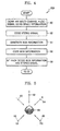
- FIG. 5 illustrates a multi-channel audio signal.
- Non-surround components 60, 62, and 64 and surround components 66 and 68 are included in the multi-channel audio signal.
- reference numeral 69 denotes a listener.
- Equation 1 can be simplified as shown in Equation 2.
- L m R m W L R + C C + H 1 H 2 H 3 H 4 ⁇ LS RS
- L R + C C are the non-surround components 60, 62, and 64 included in the multi-channel audio signal
- LS RS are the surround components 66 and 68 included in the multi-channel audio signal
- H 1 H 2 H 3 H 4 are space information H j .
- FIG. 6 is a block diagram of an example 30A of the down mixer 30 shown in FIG. 3 .
- the down mixer 30A includes first and second multipliers 70 and 72 and a synthesizer 74.
- the first multiplier 70 of the down mixer 30A multiplies a weighed value inputted through an input terminal IN3 by non-surround components included in the multi-channel audio signal inputted through an input terminal IN4, and outputs a multiplied result to the synthesizer 74.
- the second multiplier 72 multiplies surround components included in the multi-channel audio signal inputted through the input terminal IN4 by space information and outputs a multiplied result to the synthesizer 74.
- the synthesizer 74 synthesizes results multiplied by the first and second multipliers 70 and 72 and outputs a synthesized result as a stereo signal through an output terminal OUT3.
- the subcoder 32 codes the stereo signal inputted from the down mixer 30 and outputs the coded stereo signal to the bit packing unit 38.
- the subcoder 32 can code the stereo signal in a MP3 [or an MPEG-1 layer 3 or MPEG-2 layer 3], an MPEG4-advanced audio coding (AAC), or an MPEG4-bit sliced arithmetic coding (BSAC) format.
- the side information generator 34 After operation 52, in operation 54, the side information generator 34 generates side information from the coding signal inputted from the bit packing unit 38 using the stereo signal inputted from the down mixer 30 or the multi-channel audio signal inputted through an input terminal IN2 and outputs the generated side information to the side information coder 36. Embodiments of the side information generator 34 and generation of side information performed in the side information generator 34 will be described later in detail.
- the side information coder 36 codes the side information generated by the side information generator 34 and outputs the coded side information to the bit packing unit 38.
- the side information coder 36 can quantize the side information generated by the side information generator 34, compress a quantized result, and output a compressed result as coded side information to the bit packing unit 38.
- operation 52 may be simultaneously performed when operations 54 and 56 are performed or operation 52 may be performed after operations 54 and 55 are performed.
- the bit packing unit 38 bit packs the side information coded by the side information coder 36 and stereo signal coded by the subcoder 32, transmits a bit-packed result as a coding signal to the main decoder 12 through an output terminal OUT2, and outputs the bit-packed result to the side information generator 34.
- the bit packing unit 38 sequentially repeatedly performs the operations of storing the coded side information and the coded stereo signal, outputting the stored and coded side information, and then outputting the coded stereo signal.
- the bit packing unit 38 multiplexes the coded side information by the coded stereo signal and outputs a multiplexed result as a coding signal.
- FIG. 7 is a block diagram of an example 12A of the main decoding unit 12 shown in FIG. 1 .
- the main decoding unit 12A includes a bit unpacking unit 90, a subdecoder 92, a side information decoder 94, and an up mixer 96.
- FIG. 8 is a flowchart illustrating an example 22A of the operation 22 shown in FIG. 2 .
- Operation 22A includes bit unpacking a coding signal (operation 110) and upmixing a stereo signal using side information (respective operations 112 and 114).
- the bit unpacking unit 90 of FIG. 7 inputs a coding signal having a shape of a bit stream transmitted from the main coding unit 10 through an input terminal IN5, receives the coding signal, bit unpacks the received coding signal, outputs bit-unpacked side information to the side information decoder 94, and outputs the bit-unpacked stereo signal to the subdecoder 92.
- the bit unpacking unit 90 bit unpacks a result bit-unpacked by the bit packing unit 38 of FIG. 3 .
- the subdecoder 92 decodes the bit-unpacked stereo signal and outputs a decoded result to the up mixer 96
- the side information decoder 94 decodes the bit-unpacked side information and outputs a decoded result to the up mixer 96.
- the side information decoder 94 restores side information, inverse quantizes a restored result, and outputs an inverse-quantized result as decoded side information to the up mixer 96.
- the up mixer 96 up mixes the stereo signal decoded by the subdecoder 92 using side information decoded by the side information decoder 94 and outputs a up-mixed result as a restored multi-channel audio signal through an output terminal OUT4.
- FIG. 9 is a block diagram of an example 96A of the up mixer 96 shown in FIG. 7 .
- the up mixer 96A includes respective third and fourth multipliers 130 and 134, a non-surround component restoring unit 132, and an operation unit 136.
- the third multiplier 130 of FIG. 9 multiplies the decoded stereo signal inputted from the subdecoder 92 through an input terminal IN6 by inverse space information G and outputs a multiplied result to the operation unit 136.
- the inverse space information G is an inverse of space information, as shown in Equation 3 and may be changed according to an environment in which a multi-channel audio signal restored by the main decoding unit 12 is reproduced, or determined in advance.
- G ⁇ H - 1
- the non-surround component restoring unit 132 generates non-surround components from the decoded stereo signal inputted from the subdecoder 92 through an input terminal IN6 and outputs the generated non-surround components to the fourth multiplier 134. For example, when the down mixer 30 of FIG. 3 down mixes the multi-channel audio signal as shown in Equation 2, the non-surround component restoring unit 132 can generate the non-surround components using Equation 4.
- L' is a left (channel) component among the non-surround components generated by the non-surround component restoring unit 132
- R' is a right (channel) component among the non-surround components generated by the non-surround component restoring unit 132
- C' is a center (channel) component among the non-surround components generated by the non-surround component restoring unit 132
- L m ' is a left (channel) component included in the stereo signal decoded by the subdecoder 92 of FIG. 7
- R m ' is a right (channel) component included in the stereo signal decoded by the subdecoder 92.
- the fourth multiplier 134 multiplies the non-surround components inputted from the non-surround component restoring unit 132 by the inverse space information G and a weighed value W and outputs a multiplied result to the operation unit 136.
- the up mixer 96A of FIG. 9 may not include the non-surround component restoring unit 132.
- the non-surround components excluding surround components from the decoded stereo signal are directly inputted into the fourth multiplier 134 of the up mixer 96A from outside through an input terminal IN7.
- the operation unit 136 restores the multi-channel audio signal using the results multiplied by the third and fourth multipliers 130 and 134 and the decoded side information inputted from the side information decoder 94 through an input terminal IN8 and outputs the restored multi-channel audio signal through an output terminal OUT4.
- FIG. 10 is a block diagram of an example 34 A of the side information generator 34 shown in FIG. 3 .
- the side information generator 34A includes a surround component restoring unit 150 and a ratio generator 152.
- the surround component restoring unit 150 restores surround components from the coding signal inputted from the bit packing unit 38 through an input terminal IN9 and outputs the restored surround components to the ratio generator 152.
- the surround component restoring unit 150 is shown to optionally include a bit unpacking unit 160, a subdecoder 162, a side information decoder 164, and an up mixer 166 as shown in FIG. 10 .
- the bit unpacking unit 160, the subdecoder 162, the side information decoder 164, and the up mixer 166 perform the same functions as the bit unpacking unit 90, the subdecoder 92, the side information decoder 94, and the up mixer 96 of FIG. 7 , and thus, a detailed description thereof will be omitted.
- the ratio generator 152 generates the ratio of the restored surround components outputted from the surround component restoring unit 150 to the multi-channel audio signal inputted through an input terminal IN10 and outputs the generated ratio as side information through an output terminal OUT5 to the side information decoder 36.
- the ratio generator 152 can generate side information using Equation 5.
- SI LS ⁇ LS , RS ⁇ RS
- SI side information generated by the ratio generator 152
- LS' is a left component among the surround components included in the multi-channel audio signal restored by the surround component restoring unit 150, for example, outputted from the up mixer 166
- RS' is a right component among the surround components included in the restored multi-channel audio signal outputted from the up mixer 166.
- the ratio of side information generated by the ratio generator 152 as shown in Equation 5 may be a power ratio or both a power ratio and a phase ratio.
- SI LS ⁇ ⁇ LS ⁇
- ⁇ RS ⁇ RS
- the ratio generator 152 generates the ratio of the restored surround components outputted from the surround component restoring unit 150 and the stereo signal inputted from the down mixer 30 through an input terminal IN10 and outputs the generated ratio as the side information to the side information decoder 36 through an output terminal OUT5.
- the ratio of the side information generated by the ratio generator 152 as shown in Equation 8 may be a power ratio or both a power ratio and a phase ratio.
- the ratio generator152 can generate the side information as shown in Equation 9 or 10
- SI LS ⁇ L m ⁇ RS ⁇ R m where
- SI LS ⁇ ⁇ LS ⁇
- FIG. 11 is a block diagram of an example 136A of the operation unit 136 shown in FIG. 9 .
- the operation unit 136A includes a first subtracter 170 and a fifth multiplier 172.
- the first subtracter 170 subtracts a result multiplied by the fourth multiplier 134 inputted through an input terminal IN12 from a result multiplied by the third multiplier 130 of FIG. 9 inputted through an input terminal IN11 and outputs a subtracted result to the fifth multiplier 172.
- the fifth multiplier 172 multiplies the subtracted result inputted from the first subtracter 170 by the side information decoded by the side information decoder 94 inputted through an input terminal IN13 and outputs a multiplied result as a restored multi-channel audio signal through an output terminal OUT6.
- LS ⁇ RS ⁇ SI ⁇ LS ⁇ RS ⁇
- SI' the decoded side information
- LS′′′ RS′′′ the subtracted result outputted from the first subtracter 170 and can be shown as Equation 12
- LS ⁇ RS ⁇ G L m ⁇ R m ⁇ - GW L ⁇ R ⁇ + C ⁇ C ⁇
- L m ⁇ R m ⁇ is the decoded stereo signal inputted from the subdecoder 92 to the third multiplier 130 through an input terminal IN6.
- the ratio generator 152 of FIG. 10 When the ratio generator 152 of FIG. 10 generates the side information using the ratio of the restored surround components and the stereo signal inputted from the down mixer 30, the structure and operation of the operation unit 136 of FIG. 9 will now be described.
- FIG. 12 is a block diagram of an example of 136B of the operation unit 136 shown in FIG. 9 .
- the operation unit 136B includes a sixth multiplier 190 and a second subtracter 192.
- the sixth multiplier 190 multiplies a result multiplied by the third multiplier 130 inputted through an input terminal IN14 by a result multiplied by the side information decoded by the side information decoder 94 inputted through an input terminal IN15 and outputs a multiplied result to the second subtracter 192.
- the second subtracter 192 subtracts the result multiplied by the fourth multiplier 134 inputted through an input terminal IN16 from the result multiplied by the sixth multiplier 190 and outputs a subtracted result as a restored multi-channel audio signal through an output terminal OUT7.
- LS ⁇ RS ⁇ G ⁇ SI ⁇ ⁇ L m ⁇ R m ⁇ - G ⁇ W ⁇ LS ⁇ RS ⁇
- LS′′′ RS′′′ is the surround components of the restored multi-channel audio signal outputted from the second subtracter 192
- G ⁇ SI ⁇ ⁇ L m ⁇ R m ⁇ is the result multiplied by the sixth multiplier 190
- G ⁇ W ⁇ LS ⁇ RS ⁇ is the result multiplied by the fourth multiplier 134
- LS ⁇ RS ⁇ is the same as that of FIG. 12 .
- the surround components are restored using the restored non-surround components.
- crosstalk can be prevented from occurring when the surround components and the non-surround components are restored together.
- the multi-channel audio signal can be up-mixed only using a small amount of side information, the amount of data of the side information to be transmitted from the main coding unit 10 to the main decoding unit 12 can be reduced, a compression efficiency of a channel, that is, a transmission efficiency, can be maximized, since surround components are included in the stereo signal unlike in conventional spatial audio coding (SAC), a multi-channel effect can be obtained only using a stereo speaker through a restored multi-channel audio signal so that a realistic sound quality can be provided, conventional binaural cue coding (BCC) can be replaced, since the audio signal is decoded using inverse space information effectively expressed in consideration of the position of a speaker in a multi-channel audio system, an
Landscapes
- Engineering & Computer Science (AREA)
- Physics & Mathematics (AREA)
- Signal Processing (AREA)
- Acoustics & Sound (AREA)
- Multimedia (AREA)
- Mathematical Physics (AREA)
- Computational Linguistics (AREA)
- Health & Medical Sciences (AREA)
- Audiology, Speech & Language Pathology (AREA)
- Human Computer Interaction (AREA)
- Stereophonic System (AREA)
Applications Claiming Priority (2)
| Application Number | Priority Date | Filing Date | Title |
|---|---|---|---|
| KR1020040099741A KR100682904B1 (ko) | 2004-12-01 | 2004-12-01 | 공간 정보를 이용한 다채널 오디오 신호 처리 장치 및 방법 |
| EP05257268A EP1667111A1 (en) | 2004-12-01 | 2005-11-25 | Apparatus and method for processing multi-channel audio signal using space information |
Related Parent Applications (1)
| Application Number | Title | Priority Date | Filing Date |
|---|---|---|---|
| EP05257268A Division EP1667111A1 (en) | 2004-12-01 | 2005-11-25 | Apparatus and method for processing multi-channel audio signal using space information |
Publications (1)
| Publication Number | Publication Date |
|---|---|
| EP2911151A1 true EP2911151A1 (en) | 2015-08-26 |
Family
ID=35788801
Family Applications (2)
| Application Number | Title | Priority Date | Filing Date |
|---|---|---|---|
| EP15163384.9A Ceased EP2911151A1 (en) | 2004-12-01 | 2005-11-25 | Apparatus and method for processing multi-channel audio signal using space information |
| EP05257268A Ceased EP1667111A1 (en) | 2004-12-01 | 2005-11-25 | Apparatus and method for processing multi-channel audio signal using space information |
Family Applications After (1)
| Application Number | Title | Priority Date | Filing Date |
|---|---|---|---|
| EP05257268A Ceased EP1667111A1 (en) | 2004-12-01 | 2005-11-25 | Apparatus and method for processing multi-channel audio signal using space information |
Country Status (5)
| Country | Link |
|---|---|
| US (4) | US7961889B2 (zh) |
| EP (2) | EP2911151A1 (zh) |
| JP (3) | JP4921781B2 (zh) |
| KR (1) | KR100682904B1 (zh) |
| CN (3) | CN102568486B (zh) |
Families Citing this family (43)
| Publication number | Priority date | Publication date | Assignee | Title |
|---|---|---|---|---|
| JP4988716B2 (ja) | 2005-05-26 | 2012-08-01 | エルジー エレクトロニクス インコーポレイティド | オーディオ信号のデコーディング方法及び装置 |
| WO2006126843A2 (en) * | 2005-05-26 | 2006-11-30 | Lg Electronics Inc. | Method and apparatus for decoding audio signal |
| JP5113049B2 (ja) * | 2005-07-29 | 2013-01-09 | エルジー エレクトロニクス インコーポレイティド | 符号化されたオーディオ信号の生成方法及びオーディオ信号の処理方法 |
| WO2007013783A1 (en) * | 2005-07-29 | 2007-02-01 | Lg Electronics Inc. | Method for processing audio signal |
| CA2620030C (en) * | 2005-08-30 | 2011-08-23 | Lg Electronics Inc. | Method and apparatus for decoding an audio signal |
| AU2006291689B2 (en) * | 2005-09-14 | 2010-11-25 | Lg Electronics Inc. | Method and apparatus for decoding an audio signal |
| JP4944902B2 (ja) * | 2006-01-09 | 2012-06-06 | ノキア コーポレイション | バイノーラルオーディオ信号の復号制御 |
| US20090028344A1 (en) * | 2006-01-19 | 2009-01-29 | Lg Electronics Inc. | Method and Apparatus for Processing a Media Signal |
| KR100991795B1 (ko) | 2006-02-07 | 2010-11-04 | 엘지전자 주식회사 | 부호화/복호화 장치 및 방법 |
| EP1989920B1 (en) * | 2006-02-21 | 2010-01-20 | Koninklijke Philips Electronics N.V. | Audio encoding and decoding |
| EP1853092B1 (en) | 2006-05-04 | 2011-10-05 | LG Electronics, Inc. | Enhancing stereo audio with remix capability |
| US8027479B2 (en) | 2006-06-02 | 2011-09-27 | Coding Technologies Ab | Binaural multi-channel decoder in the context of non-energy conserving upmix rules |
| JP5238706B2 (ja) | 2006-09-29 | 2013-07-17 | エルジー エレクトロニクス インコーポレイティド | オブジェクトベースオーディオ信号のエンコーディング/デコーディング方法及びその装置 |
| CN101479785B (zh) * | 2006-09-29 | 2013-08-07 | Lg电子株式会社 | 用于编码和解码基于对象的音频信号的方法和装置 |
| EP2084901B1 (en) * | 2006-10-12 | 2015-12-09 | LG Electronics Inc. | Apparatus for processing a mix signal and method thereof |
| JP5023662B2 (ja) | 2006-11-06 | 2012-09-12 | ソニー株式会社 | 信号処理システム、信号送信装置、信号受信装置およびプログラム |
| EP2092516A4 (en) | 2006-11-15 | 2010-01-13 | Lg Electronics Inc | METHOD AND APPARATUS FOR AUDIO SIGNAL DECODING |
| US8265941B2 (en) | 2006-12-07 | 2012-09-11 | Lg Electronics Inc. | Method and an apparatus for decoding an audio signal |
| JP5302207B2 (ja) * | 2006-12-07 | 2013-10-02 | エルジー エレクトロニクス インコーポレイティド | オーディオ処理方法及び装置 |
| EP2595151A3 (en) * | 2006-12-27 | 2013-11-13 | Electronics and Telecommunications Research Institute | Transcoding apparatus |
| WO2008084427A2 (en) * | 2007-01-10 | 2008-07-17 | Koninklijke Philips Electronics N.V. | Audio decoder |
| KR20090122221A (ko) * | 2007-02-13 | 2009-11-26 | 엘지전자 주식회사 | 오디오 신호 처리 방법 및 장치 |
| WO2008150141A1 (en) * | 2007-06-08 | 2008-12-11 | Lg Electronics Inc. | A method and an apparatus for processing an audio signal |
| US8391513B2 (en) * | 2007-10-16 | 2013-03-05 | Panasonic Corporation | Stream synthesizing device, decoding unit and method |
| MX2010004220A (es) * | 2007-10-17 | 2010-06-11 | Fraunhofer Ges Forschung | Codificacion de audio usando mezcla descendente. |
| EP2624253A3 (en) * | 2007-10-22 | 2013-11-06 | Electronics and Telecommunications Research Institute | Multi-object audio encoding and decoding method and apparatus thereof |
| KR101505831B1 (ko) * | 2007-10-30 | 2015-03-26 | 삼성전자주식회사 | 멀티 채널 신호의 부호화/복호화 방법 및 장치 |
| KR100971700B1 (ko) | 2007-11-07 | 2010-07-22 | 한국전자통신연구원 | 공간큐 기반의 바이노럴 스테레오 합성 장치 및 그 방법과,그를 이용한 바이노럴 스테레오 복호화 장치 |
| WO2009068085A1 (en) * | 2007-11-27 | 2009-06-04 | Nokia Corporation | An encoder |
| KR101227932B1 (ko) * | 2011-01-14 | 2013-01-30 | 전자부품연구원 | 다채널 멀티트랙 오디오 시스템 및 오디오 처리 방법 |
| EP2720223A2 (en) * | 2011-06-07 | 2014-04-16 | Samsung Electronics Co., Ltd. | Audio signal processing method, audio encoding apparatus, audio decoding apparatus, and terminal adopting the same |
| KR20130093798A (ko) | 2012-01-02 | 2013-08-23 | 한국전자통신연구원 | 다채널 신호 부호화 및 복호화 장치 및 방법 |
| WO2013106322A1 (en) * | 2012-01-11 | 2013-07-18 | Dolby Laboratories Licensing Corporation | Simultaneous broadcaster -mixed and receiver -mixed supplementary audio services |
| EP2875511B1 (en) | 2012-07-19 | 2018-02-21 | Dolby International AB | Audio coding for improving the rendering of multi-channel audio signals |
| EP2717261A1 (en) * | 2012-10-05 | 2014-04-09 | Fraunhofer-Gesellschaft zur Förderung der angewandten Forschung e.V. | Encoder, decoder and methods for backward compatible multi-resolution spatial-audio-object-coding |
| ES2641538T3 (es) * | 2013-09-12 | 2017-11-10 | Dolby International Ab | Codificación de contenido de audio multicanal |
| CN103700372B (zh) * | 2013-12-30 | 2016-10-05 | 北京大学 | 一种基于正交解相关技术的参数立体声编码、解码方法 |
| ES2709117T3 (es) * | 2014-10-01 | 2019-04-15 | Dolby Int Ab | Codificador y decodificador de audio |
| EP3067885A1 (en) * | 2015-03-09 | 2016-09-14 | Fraunhofer-Gesellschaft zur Förderung der angewandten Forschung e.V. | Apparatus and method for encoding or decoding a multi-channel signal |
| CN105405445B (zh) * | 2015-12-10 | 2019-03-22 | 北京大学 | 一种基于声道间传递函数的参数立体声编码、解码方法 |
| EP3182406B1 (en) * | 2015-12-16 | 2020-04-01 | Harman Becker Automotive Systems GmbH | Sound reproduction with active noise control in a helmet |
| CN106774930A (zh) * | 2016-12-30 | 2017-05-31 | 中兴通讯股份有限公司 | 一种数据处理方法、装置及采集设备 |
| WO2022164229A1 (ko) * | 2021-01-27 | 2022-08-04 | 삼성전자 주식회사 | 오디오 처리 장치 및 방법 |
Citations (1)
| Publication number | Priority date | Publication date | Assignee | Title |
|---|---|---|---|---|
| US20040091118A1 (en) * | 1996-07-19 | 2004-05-13 | Harman International Industries, Incorporated | 5-2-5 Matrix encoder and decoder system |
Family Cites Families (31)
| Publication number | Priority date | Publication date | Assignee | Title |
|---|---|---|---|---|
| US5046098A (en) * | 1985-03-07 | 1991-09-03 | Dolby Laboratories Licensing Corporation | Variable matrix decoder with three output channels |
| US4799260A (en) * | 1985-03-07 | 1989-01-17 | Dolby Laboratories Licensing Corporation | Variable matrix decoder |
| JPH0479599A (ja) * | 1990-07-19 | 1992-03-12 | Victor Co Of Japan Ltd | 定位可変音響信号記録再生装置 |
| JPH04137900A (ja) * | 1990-09-27 | 1992-05-12 | Pioneer Electron Corp | 信号処理装置及び音響再生装置 |
| US5291557A (en) | 1992-10-13 | 1994-03-01 | Dolby Laboratories Licensing Corporation | Adaptive rematrixing of matrixed audio signals |
| EP0631458B1 (en) | 1993-06-22 | 2001-11-07 | Deutsche Thomson-Brandt Gmbh | Method for obtaining a multi-channel decoder matrix |
| US5771295A (en) * | 1995-12-26 | 1998-06-23 | Rocktron Corporation | 5-2-5 matrix system |
| US5970152A (en) * | 1996-04-30 | 1999-10-19 | Srs Labs, Inc. | Audio enhancement system for use in a surround sound environment |
| KR100206333B1 (ko) | 1996-10-08 | 1999-07-01 | 윤종용 | 두개의 스피커를 이용한 멀티채널 오디오 재생장치및 방법 |
| EP1025743B1 (en) * | 1997-09-16 | 2013-06-19 | Dolby Laboratories Licensing Corporation | Utilisation of filtering effects in stereo headphone devices to enhance spatialization of source around a listener |
| CA2365529C (en) * | 1999-04-07 | 2011-08-30 | Dolby Laboratories Licensing Corporation | Matrix improvements to lossless encoding and decoding |
| US6463414B1 (en) * | 1999-04-12 | 2002-10-08 | Conexant Systems, Inc. | Conference bridge processing of speech in a packet network environment |
| FI113147B (fi) | 2000-09-29 | 2004-02-27 | Nokia Corp | Menetelmä ja signaalinkäsittelylaite stereosignaalien muuntamiseksi kuulokekuuntelua varten |
| JP2002291100A (ja) * | 2001-03-27 | 2002-10-04 | Victor Co Of Japan Ltd | オーディオ信号再生方法、及びパッケージメディア |
| US6996239B2 (en) * | 2001-05-03 | 2006-02-07 | Harman International Industries, Inc. | System for transitioning from stereo to simulated surround sound |
| US7006636B2 (en) * | 2002-05-24 | 2006-02-28 | Agere Systems Inc. | Coherence-based audio coding and synthesis |
| US7292901B2 (en) | 2002-06-24 | 2007-11-06 | Agere Systems Inc. | Hybrid multi-channel/cue coding/decoding of audio signals |
| US7644003B2 (en) * | 2001-05-04 | 2010-01-05 | Agere Systems Inc. | Cue-based audio coding/decoding |
| US20030035553A1 (en) | 2001-08-10 | 2003-02-20 | Frank Baumgarte | Backwards-compatible perceptual coding of spatial cues |
| US6990210B2 (en) * | 2001-11-28 | 2006-01-24 | C-Media Electronics, Inc. | System for headphone-like rear channel speaker and the method of the same |
| DE60326782D1 (de) | 2002-04-22 | 2009-04-30 | Koninkl Philips Electronics Nv | Dekodiervorrichtung mit Dekorreliereinheit |
| EP1500083B1 (en) * | 2002-04-22 | 2006-06-28 | Koninklijke Philips Electronics N.V. | Parametric multi-channel audio representation |
| CN1650528B (zh) * | 2002-05-03 | 2013-05-22 | 哈曼国际工业有限公司 | 多信道下混频设备 |
| AU2003281128A1 (en) | 2002-07-16 | 2004-02-02 | Koninklijke Philips Electronics N.V. | Audio coding |
| CN100349207C (zh) * | 2003-01-14 | 2007-11-14 | 北京阜国数字技术有限公司 | 高频耦合的伪小波5声道音频编/解码方法 |
| DE602004002390T2 (de) * | 2003-02-11 | 2007-09-06 | Koninklijke Philips Electronics N.V. | Audiocodierung |
| US7394903B2 (en) * | 2004-01-20 | 2008-07-01 | Fraunhofer-Gesellschaft Zur Forderung Der Angewandten Forschung E.V. | Apparatus and method for constructing a multi-channel output signal or for generating a downmix signal |
| US7391870B2 (en) * | 2004-07-09 | 2008-06-24 | Fraunhofer-Gesellschaft Zur Foerderung Der Angewandten Forschung E V | Apparatus and method for generating a multi-channel output signal |
| EP1769491B1 (en) * | 2004-07-14 | 2009-09-30 | Koninklijke Philips Electronics N.V. | Audio channel conversion |
| JP5106115B2 (ja) * | 2004-11-30 | 2012-12-26 | アギア システムズ インコーポレーテッド | オブジェクト・ベースのサイド情報を用いる空間オーディオのパラメトリック・コーディング |
| US7903824B2 (en) * | 2005-01-10 | 2011-03-08 | Agere Systems Inc. | Compact side information for parametric coding of spatial audio |
-
2004
- 2004-12-01 KR KR1020040099741A patent/KR100682904B1/ko active IP Right Grant
-
2005
- 2005-08-25 US US11/210,908 patent/US7961889B2/en active Active
- 2005-11-22 CN CN201210008276.5A patent/CN102568486B/zh active Active
- 2005-11-22 CN CN201210014602.3A patent/CN102568487B/zh active Active
- 2005-11-22 CN CN2005101239025A patent/CN1783728B/zh active Active
- 2005-11-25 EP EP15163384.9A patent/EP2911151A1/en not_active Ceased
- 2005-11-25 EP EP05257268A patent/EP1667111A1/en not_active Ceased
- 2005-12-01 JP JP2005348003A patent/JP4921781B2/ja active Active
-
2011
- 2011-05-23 US US13/113,826 patent/US8824690B2/en active Active
- 2011-11-30 JP JP2011262993A patent/JP5643180B2/ja active Active
-
2013
- 2013-08-12 JP JP2013167924A patent/JP6039516B2/ja active Active
-
2014
- 2014-09-01 US US14/474,222 patent/US9232334B2/en active Active
-
2015
- 2015-12-11 US US14/965,994 patent/US9552820B2/en active Active
Patent Citations (1)
| Publication number | Priority date | Publication date | Assignee | Title |
|---|---|---|---|---|
| US20040091118A1 (en) * | 1996-07-19 | 2004-05-13 | Harman International Industries, Incorporated | 5-2-5 Matrix encoder and decoder system |
Non-Patent Citations (3)
| Title |
|---|
| "Binaural Cue Coding Applied to Stereo and Multi-Channel Audio Compression", 112 AES CONVENTION, PREPRINT, P. 5574 |
| "High-quality Parametric Spatial Audio Coding at Low Bitrates", 116TH AES CONVENTION, PREPRINT, P. 6072 |
| DAVID GRIESINGER: "Progress in 5-2-5 Matrix Systems", 103RD AES CONVENTION, 26 September 1997 (1997-09-26), New York, pages 1 - 34, XP007900011 * |
Also Published As
| Publication number | Publication date |
|---|---|
| US20160099002A1 (en) | 2016-04-07 |
| JP2013251919A (ja) | 2013-12-12 |
| CN1783728A (zh) | 2006-06-07 |
| US20110224993A1 (en) | 2011-09-15 |
| CN1783728B (zh) | 2012-03-21 |
| JP2012070428A (ja) | 2012-04-05 |
| US20060116886A1 (en) | 2006-06-01 |
| US7961889B2 (en) | 2011-06-14 |
| CN102568487B (zh) | 2014-09-17 |
| US9232334B2 (en) | 2016-01-05 |
| JP2006166447A (ja) | 2006-06-22 |
| CN102568486A (zh) | 2012-07-11 |
| US9552820B2 (en) | 2017-01-24 |
| US8824690B2 (en) | 2014-09-02 |
| CN102568487A (zh) | 2012-07-11 |
| KR100682904B1 (ko) | 2007-02-15 |
| CN102568486B (zh) | 2016-01-13 |
| JP6039516B2 (ja) | 2016-12-07 |
| EP1667111A1 (en) | 2006-06-07 |
| KR20060060927A (ko) | 2006-06-07 |
| JP5643180B2 (ja) | 2014-12-17 |
| JP4921781B2 (ja) | 2012-04-25 |
| US20150131799A1 (en) | 2015-05-14 |
Similar Documents
| Publication | Publication Date | Title |
|---|---|---|
| EP2911151A1 (en) | Apparatus and method for processing multi-channel audio signal using space information | |
| JP4601669B2 (ja) | マルチチャネル信号またはパラメータデータセットを生成する装置および方法 | |
| EP1866911B1 (en) | Scalable multi-channel audio coding | |
| US20170236523A1 (en) | Audio decoder for audio channel reconstruction | |
| US8654985B2 (en) | Stereo compatible multi-channel audio coding | |
| EP1908056B1 (en) | Concept for bridging the gap between parametric multi-channel audio coding and matrixed-surround multi-channel coding | |
| TWI393119B (zh) | 多通道編碼器、編碼方法、電腦程式產品及多通道解碼器 | |
| EP2112652B1 (en) | Apparatus and method for combining multiple parametrically coded audio sources | |
| EP1869668B1 (en) | Adaptive residual audio coding | |
| EP1758100B1 (en) | Audio signal encoder and audio signal decoder | |
| US8090587B2 (en) | Method and apparatus for encoding/decoding multi-channel audio signal | |
| KR101129877B1 (ko) | 음향 신호 복호 장치 | |
| US20140321652A1 (en) | Parametric stereo upmix apparatus, a parametric stereo decoder, a parametric stereo downmix apparatus, a parametric stereo encoder | |
| NO340450B1 (no) | Forbedret koding og parameterfremstilling av flerkanals nedblandet objektkoding | |
| WO2006035810A1 (ja) | スケーラブル符号化装置、スケーラブル復号装置、及びこれらの方法 |
Legal Events
| Date | Code | Title | Description |
|---|---|---|---|
| PUAI | Public reference made under article 153(3) epc to a published international application that has entered the european phase |
Free format text: ORIGINAL CODE: 0009012 |
|
| AC | Divisional application: reference to earlier application |
Ref document number: 1667111 Country of ref document: EP Kind code of ref document: P |
|
| AK | Designated contracting states |
Kind code of ref document: A1 Designated state(s): DE FR GB NL |
|
| 17P | Request for examination filed |
Effective date: 20160225 |
|
| RBV | Designated contracting states (corrected) |
Designated state(s): DE FR GB NL |
|
| 17Q | First examination report despatched |
Effective date: 20180119 |
|
| STAA | Information on the status of an ep patent application or granted ep patent |
Free format text: STATUS: THE APPLICATION HAS BEEN REFUSED |
|
| 18R | Application refused |
Effective date: 20181208 |