EP0631458B1 - Method for obtaining a multi-channel decoder matrix - Google Patents
Method for obtaining a multi-channel decoder matrix Download PDFInfo
- Publication number
- EP0631458B1 EP0631458B1 EP19940109238 EP94109238A EP0631458B1 EP 0631458 B1 EP0631458 B1 EP 0631458B1 EP 19940109238 EP19940109238 EP 19940109238 EP 94109238 A EP94109238 A EP 94109238A EP 0631458 B1 EP0631458 B1 EP 0631458B1
- Authority
- EP
- European Patent Office
- Prior art keywords
- matrix
- channel
- decoder
- encoder
- data
- Prior art date
- Legal status (The legal status is an assumption and is not a legal conclusion. Google has not performed a legal analysis and makes no representation as to the accuracy of the status listed.)
- Expired - Lifetime
Links
Images
Classifications
-
- H—ELECTRICITY
- H04—ELECTRIC COMMUNICATION TECHNIQUE
- H04H—BROADCAST COMMUNICATION
- H04H20/00—Arrangements for broadcast or for distribution combined with broadcast
- H04H20/86—Arrangements characterised by the broadcast information itself
- H04H20/88—Stereophonic broadcast systems
-
- H—ELECTRICITY
- H04—ELECTRIC COMMUNICATION TECHNIQUE
- H04N—PICTORIAL COMMUNICATION, e.g. TELEVISION
- H04N5/00—Details of television systems
- H04N5/44—Receiver circuitry for the reception of television signals according to analogue transmission standards
- H04N5/60—Receiver circuitry for the reception of television signals according to analogue transmission standards for the sound signals
- H04N5/602—Receiver circuitry for the reception of television signals according to analogue transmission standards for the sound signals for digital sound signals
- H04N5/605—Receiver circuitry for the reception of television signals according to analogue transmission standards for the sound signals for digital sound signals according to the NICAM system
-
- H—ELECTRICITY
- H04—ELECTRIC COMMUNICATION TECHNIQUE
- H04S—STEREOPHONIC SYSTEMS
- H04S3/00—Systems employing more than two channels, e.g. quadraphonic
- H04S3/02—Systems employing more than two channels, e.g. quadraphonic of the matrix type, i.e. in which input signals are combined algebraically, e.g. after having been phase shifted with respect to each other
Definitions
- the present invention relates to a method for obtaining a multi-channel decoder matrix and to the use of such method in decoder devices.
- a universal and compatible multi-channel sound system applicable to sound and television broadcasting like satellite or terrestrial TV broadcasting, digital audio broadcasting (terrestrial and satellite), as well as other non-broadcasting media, e.g.,
- the ISO/MPEG-Audio Multichannel system is an audio subband coding system, which can be used to transfer high quality digital multi-channel and/or multi-lingual audio information on channels with limited capacity.
- One of the basic features is the backwards compatibility to ISO 11172-3 IS coded mono, stereo or dual channel audio programs. It is designed for use in different applications.
- the three front loudspeaker channels ensure sufficient directional stability and clarity of the picture related frontal images, according to the common practice in the cinema.
- the dominant benefit is the "stable center", which is guaranteed at any location of the listener and important for most of the dialogue.
- the 3/2-stereo format has been found to be the appropriate improvement of two-channel stereophony.
- the addition of one pair of surround loudspeaker channels allows improved realism of auditory ambience.
- the transmission of the five audio signals of a 3/2 sound system requires five transmission channels (although, in the context of bit-rate reduced signals, these are not necessarily totally independent).
- the source sound signals are generally combined in a linear matrix prior to encoding.
- These combined signals (and their transmission channels) are identified by the notation T1, T2, T3, T4 and T5.
- an ISO 11172-3 IS audio decoder properly decodes the basic stereo information, consisting of basic left and right channels.
- the signals in these channels constitute an appropriate downmix of the audio information in all channels.
- the parameter tc_allocation contains information on the transmission channel allocation in a subband group: tc_allocation T3 T4 T5 0 L R C 1 L R LS 2 L R RS 3 L C LS 4 L C RS 5 L LS RS 6 R C LS 7 R C RS 8 R LS RS 9 C LS RS 10 L R - 11 LS RS - 12 L - - 13 R - - 14 C - - 15 - - - -
- Equation (1) and (2) can be represented by a multichannel (MC) encoder matrix.
- MC multichannel
- the inverse matrix is required to extract the values L, R, C, Ls and Rs.
- Some (e.g. 10) bits are transmitted, which represent e.g. the values x and y, center YES/NO, surround NO/MONO/STEREO, content of T3, T4 and T5. These bits can be used to address in the decoder a large memory in which the corresponding inverse matrices are listed. It is to expensive to implement all decoder matrix combinations in a memory table within a consumer decoder device, therefore the number of combinations must be reduced.
- the current encoder matrix can be reconstructed in the decoder using the related transmitted information. Then, the required decoder matrix can be computed from the reconstructed encoder matrix. This is possible due to the fact that the necessary computation time is significant lower than the required computation time for a decoder audio signal filter.
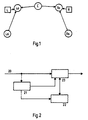
- Fig. 1 the left and right main channels L and R are depicted together with an additional center channel C and surround channels Ls and Rs.
- MPEG1/MPEG2 MPEG1/MPEG2
- the decoder matrices for each of the 11 subband groups per frame are indicated by the following header bits: Bitstream Information No./frame Bits Total MPEG1 MODE 1 2 2 MPEG2 Center 1 1 1 -"- Surround 1 2 2 -"- Presentation Matrix 1 2 2 -"- tc_allocation [1 or] 11 3 33 Sum 10 40
- the multichannel feature can be restricted to the MPEG1 stereo and joint_stereo mode. But this means that combinations like 1/2 and 1/1 or 1/0 + 1/0 + 2/0 are not allowed.
- Signal Configuration table MPEG1 Mode MPEG2 Center Surround Signal Configuration no LRC (3/0) yes mono LRCS (3/1) stereo LRCLsRs (3/2) Stereo & Joint Stereo second stereo LRCL 2 R 2 (3/0 + 2/0) no LR (no MC) no mono LRS (2/1) stereo LRLsRs (2/2) second stereo LRL 2 R 2 (2/0 + 2/0) Dual no M 1 M 2 (no MC) no Single no M (no MC) no Remark: 'no MC' does not mean 'no ML'
- the presentationmatrix information can be used to find out, how the basic stereo information Lo and Ro has been generated in the encoder (single_channel and dual_channel are not allowed). Again, all combinations are listed in the next table. At present, one value of the presentation matrix is not fixed yet, but is set to -6 dB in the next table.
- Compatible Basic stereo stable Signal Config. Presentation Matrix Xo LRCLsRs (3/2) -3 dB S.; -3 dB C. X + 0.707 C + 0.707 Xs -6 dB S.; -3 dB C. X + 0.707 C + 0.5 Xs - ⁇ dB S.; -3 dB C.
- tc_allocation For each signal configuration an other list is used. The table below (originally elaborated by PHILIPS) shows that again not all possibilities are allowed. tc_allocation table: Signal Config . Presentation Matrix Tc_ all.
- Encoder and decoder matrices (the second matrix column is received by matrix inversion)
- the elements and the size of the matrix can be calculated. For example:
- the channel on/off data are MPEG1 MODE stereo L+R MPEG2 Center yes C MPEG2 Surround mono S
- T1 x x x x L T2 x x x x * R T3 x x x x C T4 x x x x x S
- tc_allocation table channel allocation data
- the decoder matrix can be obtained by computing the inverse encoder matrix.
- Matrix can be carried out e.g. with Gaussian Elimination Algorithms. The following program gives an example:
- This routine needs 258 steps (including user messages and inputs) with a debugger to invert an encoder matrix with a size of 5*5 on a PC.
- the function " matinf" which needs approx. 90 ⁇ s for one 5*5 matrix inversion. This leads to a total computing time of approx. 1ms for 11 full matrix inversions.
- the MPEG decoder filter for 5 channels needs approx. 30ms computing time. I.e. the workload of the matrix inversion is only about 3.3% of the filter workload.
- the computation of the decoder matrix within the decoder does neither need the storage of 62 matrices nor need any restriction of the quantity of possible encoder matrices.
- Fig. 2 shows a block diagram for decoder matrix computations.
- the computations can be made using data extractor means 21, which extract from the MPEG data stream 20 the header information comprising the required input parameters, and memory means 22 in which the respective computation software operating on these input parameters for constructing the decoder matrix is stored and the output data of which are input together with the transmitted audio data of the MPEG data stream 20 to fast processor means 23 which apply the reconstructed decoder matrix to the audio data fed to a respective loudspeaker arrangement.
- the invention can be used in MPEG TV receivers and in the fields listed in the background paragraph.
Description
- The present invention relates to a method for obtaining a multi-channel decoder matrix and to the use of such method in decoder devices.
- There are basic shortcomings of conventional two-channel sound systems so as to allow enhanced performance in stereophonic presentation and/or multi-lingual capability. It is recognized that the improved presentation performance is desirable not only for applications with accompanying picture but also in case of audio-only applications. A universal and compatible multi-channel sound system applicable to sound and television broadcasting, like satellite or terrestrial TV broadcasting, digital audio broadcasting (terrestrial and satellite), as well as other non-broadcasting media, e.g.,
- CATV
- Cable TV Distribution
- CDAD
- Cable Digital Audio Distribution
- ENG
- Electronic News Gathering (including Satellite News Gathering)
- IPC
- Interpersonal Communications (videoconferencing, video-phone, etc.)
- ISM
- Interactive Storage Media (optical disks, etc.)
- NDB
- Network Database Services (via ATM, etc.)
- DSM
- Digital Storage Media (digital VTR, etc.)
- EC
- Electronic Cinema
- HTT
- Home Television Theatre
- ISDN
- Integrated Service Digital Network
- The ISO/MPEG-Audio Multichannel system is an audio subband coding system, which can be used to transfer high quality digital multi-channel and/or multi-lingual audio information on channels with limited capacity. One of the basic features is the backwards compatibility to ISO 11172-3 IS coded mono, stereo or dual channel audio programs. It is designed for use in different applications.
- As regards stereophonic presentation, the use of an additional center loudspeaker channel C and two surround loudspeaker channels Ls (or LS) and Rs (or RS) is recommended, augmenting the front left and right loudspeaker channels L and R. This reference sound format is referred to as "3/2-stereo" (3 front / 2 surround loudspeaker channels), and requires the transmission of five appropriately formatted sound signals.
- For picture accompanying sound applications (e.g. HDTV), the three front loudspeaker channels ensure sufficient directional stability and clarity of the picture related frontal images, according to the common practice in the cinema. The dominant benefit is the "stable center", which is guaranteed at any location of the listener and important for most of the dialogue. Additionally for audio-only applications the 3/2-stereo format has been found to be the appropriate improvement of two-channel stereophony. The addition of one pair of surround loudspeaker channels allows improved realism of auditory ambience.
- In basic terms, the transmission of the five audio signals of a 3/2 sound system requires five transmission channels (although, in the context of bit-rate reduced signals, these are not necessarily totally independent). In order that two of the transmitted signals can provide a stereo service on their own, the source sound signals are generally combined in a linear matrix prior to encoding. These combined signals (and their transmission channels) are identified by the notation T1, T2, T3, T4 and T5. For compatibility reasons, an ISO 11172-3 IS audio decoder properly decodes the basic stereo information, consisting of basic left and right channels. The signals in these channels constitute an appropriate downmix of the audio information in all channels. The appropriate downmix equations are given by the equations (T1 and T2 correspond to Lo and Ro) :
- The parameter tc_allocation contains information on the transmission channel allocation in a subband group:
tc_allocation T3 T4 T5 0 L R C 1 L R LS 2 L R RS 3 L C LS 4 L C RS 5 L LS RS 6 R C LS 7 R C RS 8 R LS RS 9 C LS RS 10 L R - 11 LS RS - 12 L - - 13 R - - 14 C - - 15 - - - - Further details are described in "ISO 11172-3 compatible low bit rate multi-channel audio coding and conventional stereo coding at lower sampling frequencies", ISO/IEC JTC1/SC29/WG11 N0403, MPEG93/479, 11. June 1993.
- It is an object of the invention to obtain a decoder matrix in a decoder device without storing a decoder matrix table containing multiple of these matrices. This object is reached by the method disclosed in claim 1.
- The values required for equations (1) and (2) can be represented by a multichannel (MC) encoder matrix. The following matrix may serve as an example:

- In a decoder, the inverse matrix is required to extract the values L, R, C, Ls and Rs. The variation of these parameters would allow a huge amount of different decoder matrices even if a lot of them are not useful or not possible.
Some (e.g. 10) bits are transmitted, which represent e.g. the values x and y, center YES/NO, surround NO/MONO/STEREO, content of T3, T4 and T5. These bits can be used to address in the decoder a large memory in which the corresponding inverse matrices are listed.
It is to expensive to implement all decoder matrix combinations in a memory table within a consumer decoder device, therefore the number of combinations must be reduced.
Advantageously, instead of adressing a decoder matrix stored in a decoder memory, at first the current encoder matrix can be reconstructed in the decoder using the related transmitted information. Then, the required decoder matrix can be computed from the reconstructed encoder matrix. This is possible due to the fact that the necessary computation time is significant lower than the required computation time for a decoder audio signal filter. - Preferred embodiments of the invention are described with reference to the accompanying drawings, which show in:
- Fig. 1
- arrangement of main, center and surround channels;
- Fig. 2
- apparatus for computing a decoder matrix.
- In Fig. 1 the left and right main channels L and R are depicted together with an additional center channel C and surround channels Ls and Rs. For compatibility reasons (MPEG1/MPEG2), not these signals but the signals Lo, Ro (which include the significant audio information) and T3, T4 and T5 are transmitted.
- The decoder matrices for each of the 11 subband groups per frame are indicated by the following header bits:
Bitstream Information No./frame Bits Total MPEG1 MODE 1 2 2 MPEG2 Center 1 1 1 -"- Surround 1 2 2 -"- Presentation Matrix 1 2 2 -"- tc_allocation [1 or] 11 3 33 Sum 10 40 - This number of bits leads theoretically to up to 1024 different decoder matrices. To reduce this large number, e.g. the multichannel feature can be restricted to the MPEG1 stereo and joint_stereo mode. But this means that combinations like 1/2 and 1/1 or 1/0 + 1/0 + 2/0 are not allowed. The remaining combinations can be seen from the following list::
Signal Configuration table: MPEG1 Mode MPEG2 Center Surround Signal Configuration no LRC (3/0) yes mono LRCS (3/1) stereo LRCLsRs (3/2) Stereo & Joint Stereo second stereo LRCL2R2 (3/0 + 2/0) no LR (no MC) no mono LRS (2/1) stereo LRLsRs (2/2) second stereo LRL2R2 (2/0 + 2/0) Dual no M1M2 (no MC) no Single no M (no MC) no Remark: 'no MC' does not mean 'no ML' - From the MPEG bitstream the presentationmatrix information can be used to find out, how the basic stereo information Lo and Ro has been generated in the encoder (single_channel and dual_channel are not allowed). Again, all combinations are listed in the next table. At present, one value of the presentation matrix is not fixed yet, but is set to -6 dB in the next table.
Compatible Basic stereo stable: Signal Config. Presentation Matrix Xo LRCLsRs (3/2) -3 dB S.; -3 dB C. X + 0.707 C + 0.707 Xs -6 dB S.; -3 dB C. X + 0.707 C + 0.5 Xs -∞ dB S.; -3 dB C. X + 0.707 C -∞ dB S.; -∞ dB C. X LRCS (3/1) -3 dB S.; -3 dB C. X + 0.707 C + 0.707 S -6 dB S.; -3 dB C. X + 0.707 C + 0.5 S -∞ dB S.; -3 dB C. X + 0.707 C -∞ dB S.; -∞ dB C. X LRCL 2 R 2 (3/0+2/0) & LRC (3/0) -3 dB S.; -3 dB C. X + 0.707 C -6 dB S.; -3 dB C. X + 0.707 C -∞ dB S.; -3 dB C. X + 0.707 C -∞ dB S.; -∞ dB C. X LRLsRs (2/2) -3 dB S.; -3 dB C. X + 0.707 Xs -6 dB S.; -3 dB C. X + 0.5 Xs -∞ dB S.; -3 dB C. X -∞ dB S.; -∞ dB C. X LRS (2/1) -3 dB S.; -3 dB C. X + 0.707 S -6 dB S.; -3 dB C. X + 0.5 S -∞ dB S.; -3 dB C. X -∞ dB S.; -∞ dB C. X LRL 2 R 2 (2/0 + 2/0) -3 dB S.; -3 dB C. X -6 dB S.; -3 dB C. X -∞ dB S.; -3 dB C. X -∞ dB S.; -∞ dB C. X - Now, all information is collected which is useful for a whole frame. Finally, the information about the allocation of the transport channels is needed, i.e. which audio channel is in which transport channel for a subband group. This information is indicated by the tc_allocation. For each signal configuration an other list is used. The table below (originally elaborated by PHILIPS) shows that again not all possibilities are allowed.
tc_allocation table: Signal Config . Presentation Matrix Tc_ all. (T1) (T2) T3 T4 T5 MTX No LRCLsRs -3dB S; -3dB C 0 L R C LS RS 1/1 (3/2) 1 C R L LS RS 2/2 2 L C R LS RS 3/3 3 Ls R C L RS 4/4 4 L Rs C LS R 5/5 5 Ls Rs C L R 6/6 6 Ls C R L RS 7/7 7 C Rs L LS R 8/8 8 - - (x/x) 9 - - (x/x) 10 - (x/x) 11 - - dyn.crosstalk (x/x) 12 - - (x/x) 13 - - (x/x) 14 - - (x/x) 15 - - (x/x) -6dB S; -3dB C 0 L R C LS RS 1/9 1 C R L LS RS 2/10 2 L C R LS RS 3/11 3 Ls R C L RS 4/12 4 L Rs C LS R 5/13 5 Ls Rs C L R 6/14 6 Ls C R L RS 7/15 7 C Rs L LS R 8/16 x - - dyn.cross talk (x/x) -∞dB S; -3dB C 0 L R C LS RS 1/17 1 C R L LS RS 2/18 2 L C R LS RS 3/19 x - - dyn. cross talk (x/x) -∞dB S; -∞dB C 0 L R C LS RS 1/20 x - - dyn. cross talk (x/x) LRCS -3dB S; -3dB C 0 L R C S - 9/21 (3/1) 1 C R L S - 10/22 2 L C R S - 11/23 3 S R C L - 12/24 4 L S C R - 13/25 x - - dyn. cross talk (x/x) -6dB S; -3dB C 0 L R C S - 9/26 1 C R L S - 10/27 2 L C R S - 11/28 3 S R C L - 12/29 4 L S C R - 13/30 x - - dyn. cross talk (x/x) -∞dB S; -3dB C 0 L R C S - 9/31 1 C R L S - 10/32 2 L C R S - 11/33 x - - dyn. cross talk (x/x) -∞dB S; -∞dB C 0 L R C S - 9/34 x - - dyn. cross talk (x/x) LRCL2R2 -3dB S; -3dB C 0 L R C (L2) (R2) 14/35 (3/0 + 2/0) 1 C R L (L2) (R2) 15/36 & LRC 2 L C R (L2) (R2) 16/37 (3/0) x - - dyn. cross talk (x/x) -6dB S; -3dB C 0 L R C (L2) (R2) 14/38 1 C R L (L2) (R2) 15/39 2 L C R (L2) (R2) 16/40 x - - dyn. cross talk (x/x) -∞dB S; -3dB C 0 L R C (L2) (R2) 14/41 1 C R L (L2) (R2) 15/42 2 L C R (L2) (R2) 16/43 x - - dyn. cross talk (x/x) -∞dB S; -∞dB C 0 L R C (L2) (R2) 14/44 x - - dyn. cross talk (x/x) LRLsRs (2/2) -3dB S; -3dB C 0 L R LS RS - 17/45 3 Ls R L RS 18/46 4 L Rs LS R - 19/47 5 Ls R L R - 20/48 x - - dyn. cross talk (x/x) -6dB S; -3dB C 0 L R LS RS - 17/49 3 Ls R L RS - 18/50 4 L Rs LS R - 19/51 5 Ls R L R - 20/52 x - - dyn. cross talk (x/x) -∞dB S; -3dB C 0 L R LS RS - 17/53 x - - dyn. cross talk (x/x) -∞dB S; -∞dB C 0 L R LS RS 17/54 x - - dyn. cross talk (x/x) LRS (2/1) -3dB S; -3dB C 0 L R S - - 21/55 3 S R L - - 22/56 4 L S R - - 23/57 x - - dyn. cross talk (x/x) -6dB S; -3dB C 0 L R S - - 21/58 3 S R L - - 22/59 4 L S R - - 23/60 x - - dyn. cross talk (x/x) -∞dB S; -∞dB C 0 L R S - - 21/61 3 4 x - - dyn. cross talk (x/x) -∞dB S; -∞dB C 0 L R S - - 21/62 3 4 x - - dyn. cross talk (x/x) LR -3dB S; -3dB C no L R (L2) (R2) - no (2/0) -6dB S; -3dB C no L R (L2) (R2) - no LRL2R2 -∞dB S; -3dB C no L R (L2) (R2) - no (2/0 +2/0) - -∞dB S; -∞dB C no L R (L2) (R2) - no - With the restriction to MPEG 1 stereo and joint_stereo only, no further matrices seem to be possible. So, the storage of 23 types leading to 62 real decoder matrices without dynamic cross talk are required.
The last row in the list above gives a matrix type/real number. All 23 encoder and decoder matrixes types are listed in the next list. - Encoder and decoder matrices:
(the second matrix column is received by matrix inversion) -


-


-


-


-


- To avoid the storage of these matrices in the decoder, from the header of the MPEG bitstream the elements and the size of the matrix can be calculated. For example:
- The channel on/off data are
MPEG1 MODE stereo L+R MPEG2 Center yes C MPEG2 Surround mono S - I.e. 4 channels:
T1 x x x x L T2 = x x x x * R T3 x x x x C T4 x x x x S - From the above channel on/off data the matrix elements X11,X12,X21 and X22 are fixed:
T1 1 0 x x L T2 = 0 1 x x * R T3 x x x x C T4 x x x x S - The presentationmatrix (channel factor data) gives useful information about the factors of the basic stereo channels. For example:
Surround -6dB = 0.5 Center -3dB = 0.707 - I.e. the matrix looks as followed:
T1 1 0 0.7 0.5 L T2 = 0 1 0.7 0.5 * R T3 x x x x C T4 x x x x S - Now, the matrix lines 3 and 4 are still missing. One can get this information form the tc_allocation table (channel allocation data), e.g. tc_allocation=2.
- Then, the encoder matrix is:
T1 1 0 0.7 0.5 L T2 = 0 1 0.7 0.5 * R T3 0 1 0 0 C T4 0 0 0 1 S - The decoder matrix can be obtained by computing the inverse encoder matrix. Matrix can be carried out e.g. with Gaussian Elimination Algorithms. The following program gives an example:


- This routine needs 258 steps (including user messages and inputs) with a debugger to invert an encoder matrix with a size of 5*5 on a PC.
- In the DSP32C library exists the function " matinf" which needs approx. 90µs for one 5*5 matrix inversion.
This leads to a total computing time of approx. 1ms for 11 full matrix inversions.
For comparison: The MPEG decoder filter for 5 channels needs approx. 30ms computing time. I.e. the workload of the matrix inversion is only about 3.3% of the filter workload. Advantageously, the computation of the decoder matrix within the decoder does neither need the storage of 62 matrices nor need any restriction of the quantity of possible encoder matrices. - Fig. 2 shows a block diagram for decoder matrix computations. The computations can be made using data extractor means 21, which extract from the
MPEG data stream 20 the header information comprising the required input parameters, and memory means 22 in which the respective computation software operating on these input parameters for constructing the decoder matrix is stored and the output data of which are input together with the transmitted audio data of theMPEG data stream 20 to fast processor means 23 which apply the reconstructed decoder matrix to the audio data fed to a respective loudspeaker arrangement. - The invention can be used in MPEG TV receivers and in the fields listed in the background paragraph.
Claims (3)
- Method for obtaining in a decoder a multi-channel (L, R, C, Ls, Rs) decoder matrix which corresponds to an encoder matrix and which is required for recovering an encoded digital audio signal from a bitstream which has been encoded using said encoder matrix, wherein in header bits in the bitstream an indication information is included which comprises channel on/off data, channel factor data, and channel allocation data, characterised by the steps:determining from said indication information the number of channels and therewith the encoder matrix size, and inserting 0/1 matrix elements corresponding to said channel on/off data into the corresponding positions within said encoder matrix to be reconstructed;determining from said channel factor data further matrix elements and inserting them into corresponding further positions within said encoder matrix to be reconstructed;determining from said channel allocation data the remaining matrix elements and inserting them into the remaining positions within said encoder matrix to be reconstructed, wherein the encoder matrix defines how the original channel signals before matrixing have been combined in order to obtain matrixed channel signals for transmission;performing a matrix inversion of the reconstructed encoder matrix in order to obtain said decoder matrix.
- Method according to claim 1, wherein basic left and right channel signals in the bitstream are compatible with the ISO 11172-3 standard.
- Usage of the method according to claim 1 or 2 in a TV receiver, a VCR, a CD player or a multi-channel sound system.
Priority Applications (1)
| Application Number | Priority Date | Filing Date | Title |
|---|---|---|---|
| EP19940109238 EP0631458B1 (en) | 1993-06-22 | 1994-06-16 | Method for obtaining a multi-channel decoder matrix |
Applications Claiming Priority (3)
| Application Number | Priority Date | Filing Date | Title |
|---|---|---|---|
| EP93401609 | 1993-06-22 | ||
| EP93401609 | 1993-06-22 | ||
| EP19940109238 EP0631458B1 (en) | 1993-06-22 | 1994-06-16 | Method for obtaining a multi-channel decoder matrix |
Publications (2)
| Publication Number | Publication Date |
|---|---|
| EP0631458A1 EP0631458A1 (en) | 1994-12-28 |
| EP0631458B1 true EP0631458B1 (en) | 2001-11-07 |
Family
ID=26134705
Family Applications (1)
| Application Number | Title | Priority Date | Filing Date |
|---|---|---|---|
| EP19940109238 Expired - Lifetime EP0631458B1 (en) | 1993-06-22 | 1994-06-16 | Method for obtaining a multi-channel decoder matrix |
Country Status (1)
| Country | Link |
|---|---|
| EP (1) | EP0631458B1 (en) |
Families Citing this family (6)
| Publication number | Priority date | Publication date | Assignee | Title |
|---|---|---|---|---|
| ES2165370T3 (en) * | 1993-06-22 | 2002-03-16 | Thomson Brandt Gmbh | METHOD FOR OBTAINING A MULTICHANNEL DECODING MATRIX. |
| US6005948A (en) * | 1997-03-21 | 1999-12-21 | Sony Corporation | Audio channel mixing |
| CA2365529C (en) * | 1999-04-07 | 2011-08-30 | Dolby Laboratories Licensing Corporation | Matrix improvements to lossless encoding and decoding |
| US7447317B2 (en) | 2003-10-02 | 2008-11-04 | Fraunhofer-Gesellschaft Zur Foerderung Der Angewandten Forschung E.V | Compatible multi-channel coding/decoding by weighting the downmix channel |
| DE102004043521A1 (en) | 2004-09-08 | 2006-03-23 | Fraunhofer-Gesellschaft zur Förderung der angewandten Forschung e.V. | Device and method for generating a multi-channel signal or a parameter data set |
| KR100682904B1 (en) | 2004-12-01 | 2007-02-15 | 삼성전자주식회사 | Apparatus and method for processing multichannel audio signal using space information |
-
1994
- 1994-06-16 EP EP19940109238 patent/EP0631458B1/en not_active Expired - Lifetime
Also Published As
| Publication number | Publication date |
|---|---|
| EP0631458A1 (en) | 1994-12-28 |
Similar Documents
| Publication | Publication Date | Title |
|---|---|---|
| US5524054A (en) | Method for generating a multi-channel audio decoder matrix | |
| EP1568250B1 (en) | Method and apparatus for processing audio signals from a bitstream | |
| KR101356480B1 (en) | Method and apparatus for signal processing | |
| RU2129336C1 (en) | Method for transmission and/or storage of digital signals of more than one channel | |
| US5463424A (en) | Multi-channel transmitter/receiver system providing matrix-decoding compatible signals | |
| KR100421793B1 (en) | Simulating two way connectivity for one way data streams for multiple parties | |
| US5638451A (en) | Transmission and storage of multi-channel audio-signals when using bit rate-reducing coding methods | |
| KR100658222B1 (en) | 3 Dimension Digital Multimedia Broadcasting System | |
| EP0631458B1 (en) | Method for obtaining a multi-channel decoder matrix | |
| US6122382A (en) | System for processing audio surround signal | |
| CZ293070B6 (en) | Method and apparatus for encoding a plurality of digital information signals, a record medium and apparatus for decoding a received transmission signal | |
| Stoll et al. | Extension of ISO/MPEG-Audio Layer II to Multichannel Coding: The Future Standard for Broadcasting, Telecommunication, and Multimedia Applications | |
| Theile et al. | MUSICAM-Surround: A Universal Multichannel Coding System Compatible with ISO 11172-3 | |
| Grill et al. | Improved MPEG-2 audio multi-channel encoding | |
| DE3734084C2 (en) | ||
| Maher et al. | Old and new techniques for artificial stereophonic image enhancement | |
| Theile et al. | Musicam-surround: A multichannel stereo coding method | |
| McKinney et al. | ATSC digital television standard | |
| KR20110085155A (en) | Apparatus for generationg and reproducing audio data for real time audio stream and the method thereof | |
| Plogsties et al. | Conveying spatial sound using MPEG-4 | |
| KR100208004B1 (en) | Device and method for reproducing stereo audio using upper/lower channel audio signals | |
| Stoll | Status and future activities in standardization of low bit-rate audio codecs | |
| KR100516733B1 (en) | Dolby prologic audio apparatus | |
| BS | Multichannel stereophonic sound system with and without accompanying picture | |
| Meares | Sound systems for high definition television |
Legal Events
| Date | Code | Title | Description |
|---|---|---|---|
| PUAI | Public reference made under article 153(3) epc to a published international application that has entered the european phase |
Free format text: ORIGINAL CODE: 0009012 |
|
| AK | Designated contracting states |
Kind code of ref document: A1 Designated state(s): DE ES FR GB IT |
|
| 17P | Request for examination filed |
Effective date: 19950603 |
|
| 17Q | First examination report despatched |
Effective date: 19990519 |
|
| GRAG | Despatch of communication of intention to grant |
Free format text: ORIGINAL CODE: EPIDOS AGRA |
|
| GRAG | Despatch of communication of intention to grant |
Free format text: ORIGINAL CODE: EPIDOS AGRA |
|
| GRAH | Despatch of communication of intention to grant a patent |
Free format text: ORIGINAL CODE: EPIDOS IGRA |
|
| GRAH | Despatch of communication of intention to grant a patent |
Free format text: ORIGINAL CODE: EPIDOS IGRA |
|
| GRAA | (expected) grant |
Free format text: ORIGINAL CODE: 0009210 |
|
| AK | Designated contracting states |
Kind code of ref document: B1 Designated state(s): DE ES FR GB IT |
|
| REG | Reference to a national code |
Ref country code: GB Ref legal event code: 746 Effective date: 20011024 |
|
| REF | Corresponds to: |
Ref document number: 69428939 Country of ref document: DE Date of ref document: 20011213 |
|
| REG | Reference to a national code |
Ref country code: GB Ref legal event code: IF02 |
|
| REG | Reference to a national code |
Ref country code: ES Ref legal event code: FG2A Ref document number: 2165370 Country of ref document: ES Kind code of ref document: T3 |
|
| REG | Reference to a national code |
Ref country code: FR Ref legal event code: D6 |
|
| PLBE | No opposition filed within time limit |
Free format text: ORIGINAL CODE: 0009261 |
|
| STAA | Information on the status of an ep patent application or granted ep patent |
Free format text: STATUS: NO OPPOSITION FILED WITHIN TIME LIMIT |
|
| 26N | No opposition filed | ||
| PGFP | Annual fee paid to national office [announced via postgrant information from national office to epo] |
Ref country code: IT Payment date: 20100616 Year of fee payment: 17 |
|
| PGFP | Annual fee paid to national office [announced via postgrant information from national office to epo] |
Ref country code: ES Payment date: 20100713 Year of fee payment: 17 |
|
| PGFP | Annual fee paid to national office [announced via postgrant information from national office to epo] |
Ref country code: GB Payment date: 20100527 Year of fee payment: 17 Ref country code: FR Payment date: 20100722 Year of fee payment: 17 Ref country code: DE Payment date: 20100610 Year of fee payment: 17 |
|
| GBPC | Gb: european patent ceased through non-payment of renewal fee |
Effective date: 20110616 |
|
| PG25 | Lapsed in a contracting state [announced via postgrant information from national office to epo] |
Ref country code: IT Free format text: LAPSE BECAUSE OF NON-PAYMENT OF DUE FEES Effective date: 20110616 |
|
| REG | Reference to a national code |
Ref country code: FR Ref legal event code: ST Effective date: 20120229 |
|
| REG | Reference to a national code |
Ref country code: DE Ref legal event code: R119 Ref document number: 69428939 Country of ref document: DE Effective date: 20120103 |
|
| PG25 | Lapsed in a contracting state [announced via postgrant information from national office to epo] |
Ref country code: FR Free format text: LAPSE BECAUSE OF NON-PAYMENT OF DUE FEES Effective date: 20110630 Ref country code: DE Free format text: LAPSE BECAUSE OF NON-PAYMENT OF DUE FEES Effective date: 20120103 |
|
| PG25 | Lapsed in a contracting state [announced via postgrant information from national office to epo] |
Ref country code: GB Free format text: LAPSE BECAUSE OF NON-PAYMENT OF DUE FEES Effective date: 20110616 |
|
| REG | Reference to a national code |
Ref country code: ES Ref legal event code: FD2A Effective date: 20130405 |
|
| PG25 | Lapsed in a contracting state [announced via postgrant information from national office to epo] |
Ref country code: ES Free format text: LAPSE BECAUSE OF NON-PAYMENT OF DUE FEES Effective date: 20110617 |