EP2910870A1 - Refrigeration device and method for controlling same - Google Patents
Refrigeration device and method for controlling same Download PDFInfo
- Publication number
- EP2910870A1 EP2910870A1 EP12884923.9A EP12884923A EP2910870A1 EP 2910870 A1 EP2910870 A1 EP 2910870A1 EP 12884923 A EP12884923 A EP 12884923A EP 2910870 A1 EP2910870 A1 EP 2910870A1
- Authority
- EP
- European Patent Office
- Prior art keywords
- temperature side
- low
- compressor
- condenser
- refrigeration apparatus
- Prior art date
- Legal status (The legal status is an assumption and is not a legal conclusion. Google has not performed a legal analysis and makes no representation as to the accuracy of the status listed.)
- Granted
Links
Images






Classifications
-
- F—MECHANICAL ENGINEERING; LIGHTING; HEATING; WEAPONS; BLASTING
- F25—REFRIGERATION OR COOLING; COMBINED HEATING AND REFRIGERATION SYSTEMS; HEAT PUMP SYSTEMS; MANUFACTURE OR STORAGE OF ICE; LIQUEFACTION SOLIDIFICATION OF GASES
- F25B—REFRIGERATION MACHINES, PLANTS OR SYSTEMS; COMBINED HEATING AND REFRIGERATION SYSTEMS; HEAT PUMP SYSTEMS
- F25B7/00—Compression machines, plants or systems, with cascade operation, i.e. with two or more circuits, the heat from the condenser of one circuit being absorbed by the evaporator of the next circuit
-
- F—MECHANICAL ENGINEERING; LIGHTING; HEATING; WEAPONS; BLASTING
- F25—REFRIGERATION OR COOLING; COMBINED HEATING AND REFRIGERATION SYSTEMS; HEAT PUMP SYSTEMS; MANUFACTURE OR STORAGE OF ICE; LIQUEFACTION SOLIDIFICATION OF GASES
- F25B—REFRIGERATION MACHINES, PLANTS OR SYSTEMS; COMBINED HEATING AND REFRIGERATION SYSTEMS; HEAT PUMP SYSTEMS
- F25B49/00—Arrangement or mounting of control or safety devices
- F25B49/02—Arrangement or mounting of control or safety devices for compression type machines, plants or systems
-
- F—MECHANICAL ENGINEERING; LIGHTING; HEATING; WEAPONS; BLASTING
- F25—REFRIGERATION OR COOLING; COMBINED HEATING AND REFRIGERATION SYSTEMS; HEAT PUMP SYSTEMS; MANUFACTURE OR STORAGE OF ICE; LIQUEFACTION SOLIDIFICATION OF GASES
- F25B—REFRIGERATION MACHINES, PLANTS OR SYSTEMS; COMBINED HEATING AND REFRIGERATION SYSTEMS; HEAT PUMP SYSTEMS
- F25B2600/00—Control issues
- F25B2600/02—Compressor control
- F25B2600/025—Compressor control by controlling speed
- F25B2600/0251—Compressor control by controlling speed with on-off operation
-
- F—MECHANICAL ENGINEERING; LIGHTING; HEATING; WEAPONS; BLASTING
- F25—REFRIGERATION OR COOLING; COMBINED HEATING AND REFRIGERATION SYSTEMS; HEAT PUMP SYSTEMS; MANUFACTURE OR STORAGE OF ICE; LIQUEFACTION SOLIDIFICATION OF GASES
- F25B—REFRIGERATION MACHINES, PLANTS OR SYSTEMS; COMBINED HEATING AND REFRIGERATION SYSTEMS; HEAT PUMP SYSTEMS
- F25B2600/00—Control issues
- F25B2600/25—Control of valves
- F25B2600/2513—Expansion valves
-
- F—MECHANICAL ENGINEERING; LIGHTING; HEATING; WEAPONS; BLASTING
- F25—REFRIGERATION OR COOLING; COMBINED HEATING AND REFRIGERATION SYSTEMS; HEAT PUMP SYSTEMS; MANUFACTURE OR STORAGE OF ICE; LIQUEFACTION SOLIDIFICATION OF GASES
- F25B—REFRIGERATION MACHINES, PLANTS OR SYSTEMS; COMBINED HEATING AND REFRIGERATION SYSTEMS; HEAT PUMP SYSTEMS
- F25B2700/00—Sensing or detecting of parameters; Sensors therefor
- F25B2700/19—Pressures
- F25B2700/193—Pressures of the compressor
- F25B2700/1931—Discharge pressures
-
- F—MECHANICAL ENGINEERING; LIGHTING; HEATING; WEAPONS; BLASTING
- F25—REFRIGERATION OR COOLING; COMBINED HEATING AND REFRIGERATION SYSTEMS; HEAT PUMP SYSTEMS; MANUFACTURE OR STORAGE OF ICE; LIQUEFACTION SOLIDIFICATION OF GASES
- F25B—REFRIGERATION MACHINES, PLANTS OR SYSTEMS; COMBINED HEATING AND REFRIGERATION SYSTEMS; HEAT PUMP SYSTEMS
- F25B2700/00—Sensing or detecting of parameters; Sensors therefor
- F25B2700/19—Pressures
- F25B2700/193—Pressures of the compressor
- F25B2700/1933—Suction pressures
-
- F—MECHANICAL ENGINEERING; LIGHTING; HEATING; WEAPONS; BLASTING
- F25—REFRIGERATION OR COOLING; COMBINED HEATING AND REFRIGERATION SYSTEMS; HEAT PUMP SYSTEMS; MANUFACTURE OR STORAGE OF ICE; LIQUEFACTION SOLIDIFICATION OF GASES
- F25B—REFRIGERATION MACHINES, PLANTS OR SYSTEMS; COMBINED HEATING AND REFRIGERATION SYSTEMS; HEAT PUMP SYSTEMS
- F25B2700/00—Sensing or detecting of parameters; Sensors therefor
- F25B2700/21—Temperatures
- F25B2700/2104—Temperatures of an indoor room or compartment
Definitions
- the present invention relates to a refrigeration apparatus including a plurality of refrigeration cycles (refrigerant circuits), and a control method of such a refrigeration apparatus.
- Some of existing refrigeration apparatuses include a high-temperature side (or higher side, primary side) refrigeration cycle (hereinafter, high-temperature side cycle) and a low-temperature side (or lower side, secondary side) refrigeration cycle (hereinafter, low-temperature side cycle) (for example, see Patent Literature 1).
- an evaporator in the high-temperature side cycle and a condenser in the low-temperature side cycle constitute a cascade condenser.
- Patent Literature 1 Japanese Unexamined Patent Application Publication No. 2012-112615 (paragraphs [0013] to [0051], Fig. 1 to Fig. 7 )
- the controller drives an expansion valve in the low-temperature side cycle so as to narrow the path, thereby reducing the refrigerant supply to a compressor in the low-temperature side cycle.
- the controller turns off the compressor in the low-temperature side cycle, in other words stops the circulation in the low-temperature side cycle, to thereby prevent the compressor in the low-temperature side cycle from sucking an excessive amount of the refrigerant, thus preventing a pressure drop in the low-temperature side cycle.
- Such a control is called low-pressure cut-off control.
- the circulation in the low-temperature side cycle may be stopped as in the low-pressure cut-off control, when the evaporator in the low-temperature side cycle is performing a defrosting operation.
- a refrigerant of a low critical temperature such as a CO 2 refrigerant is often employed as the refrigerant in the low-temperature side cycle.
- the components constituting the low-temperature side cycle are required to have a rigid structure (for example, a sufficient wall thickness), in order to cope with the pressure increase in the low-temperature side cycle, which inevitably leads to an increase in cost as well as in weight.
- the present invention has been accomplished in view of the foregoing problem, and provides a refrigeration apparatus that suppresses an increase in pressure in a low-temperature side cycle when circulation in the low-temperature side cycle is stopped, and a control method performed by the refrigeration apparatus.
- the present invention provides a refrigeration apparatus includes a first refrigerant circuit in which a refrigerant circulates, the first refrigerant circuit including a first compressor, a first condenser, a first throttle device, and a first evaporator sequentially connected by piping, a second refrigerant circuit in which a refrigerant circulates, the second refrigerant circuit including a second compressor, a second condenser, a receiver, a second throttle device, and a second evaporator sequentially connected by piping, and a cascade condenser including the first evaporator and the second condenser and configured to heat exchange between the refrigerant flowing in the first evaporator and the refrigerant flowing in the second condenser.
- the receiver is located under the cascade condenser.
- the receiver is located under the cascade condenser. Accordingly, when the circulation in the second refrigerant circuit is stopped, the refrigerant in the second refrigerant circuit, which has been condensed and liquefied by the refrigerant in the first refrigerant circuit, is rapidly collected in the receiver, and therefore an increase in pressure in the second refrigerant circuit can be suppressed.
- Fig. 1 is a diagram showing the configuration of the refrigeration apparatus according to Embodiment 1 of the present invention.
- the refrigeration apparatus 1 includes a high-temperature side cycle 11, a low-temperature side cycle 21, a cascade condenser 51, and a controller 61.
- the high-temperature side cycle 11 corresponds to the "first refrigerant circuit" in the present invention.
- the low-temperature side cycle 21 corresponds to the "second refrigerant circuit" in the present invention.
- the high-temperature side cycle 11 includes a high-temperature side compressor 12, a high-temperature side condenser 13, a high-temperature side expansion valve 14, and a high-temperature side evaporator 15.
- the high-temperature side compressor 12 corresponds to the "first compressor" in the present invention.
- the high-temperature side condenser 13 corresponds to the "first condenser" in the present invention.
- the high-temperature side expansion valve 14 corresponds to the "first throttle device" in the present invention.
- the high-temperature side evaporator 15 corresponds to the "first evaporator" in the present invention.
- the high-temperature side compressor 12, the high-temperature side condenser 13, the high-temperature side expansion valve 14, and the high-temperature side evaporator 15 are connected in series.
- the low-temperature side cycle 21 includes a low-temperature side compressor 22, an intermediate cooler 23, a low-temperature side condenser 24, a receiver 25, a cooling unit 41, and an accumulator 26.
- the low-temperature side compressor 22 corresponds to the "second compressor" in the present invention.
- the low-temperature side condenser 24 corresponds to the "second condenser" in the present invention.
- the low-temperature side compressor 22, the intermediate cooler 23, the low-temperature side condenser 24, the receiver 25, the cooling unit 41, and the accumulator 26 are connected in series.
- a service valve 27 is provided between the outlet side of the receiver 25 and the inlet side of the cooling unit 41.
- a service valve 28 is provided between the outlet side of the cooling unit 41 and the inlet side of the accumulator 26.
- the cooling unit 41 can be separated from the refrigeration apparatus 1 by the service valves 27 and 28.
- the service valves 27 and 28 may be excluded, and the cooling unit 41 may be inseparable.
- a non-illustrated sight glass for confirming the amount or condition of the refrigerant, and a non-illustrated drier for absorbing moisture in the pipe may be provided in the low-temperature side cycle 21.
- the high-temperature side evaporator 15 and the low-temperature side condenser 24 constitute a cascade condenser 51.
- the refrigerant in the high-temperature side cycle 11 and the refrigerant in the low-temperature side cycle 21 exchange heat with each other in the cascade condenser 51.
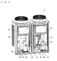
- Fig. 2 is a perspective view showing the refrigeration apparatus according to Embodiment 1.
- the receiver 25 is located under the cascade condenser 51.
- the receiver 25 and the low-temperature side condenser 24 are connected to each other via a pipe 29 having an outer diameter of, for example, 15.88 mm.
- Fig. 2 illustrates the case where the cascade condenser 51 is composed of a pair of plate-type heat exchangers connected in series and disposed side by side.
- Fig. 2 illustrates the case where the cooling unit 41 is separated.
- the cooling unit 41 includes a low-temperature side first solenoid valve 42, a low-temperature side expansion valve 43, and a low-temperature side evaporator 44.
- the low-temperature side expansion valve 43 corresponds to the "second throttle device" in the present invention.
- the low-temperature side evaporator 44 corresponds to the "second evaporator" in the present invention.
- the low-temperature side first solenoid valve 42, the low-temperature side expansion valve 43, and the low-temperature side evaporator 44 are connected in series.
- the low-temperature side evaporator 44 is located in a refrigerating room.
- Examples of the refrigerating room include a freezing showcase installed in a super market or the like, and a freezing room of a unit cooler installed in a food processing plant.
- a cooling unit utilized in an existing refrigerating room may be employed as the cooling unit 41.
- a HFC refrigerant R410A, R404A, R32, R407C
- a HFO refrigerant R407C
- a HC refrigerant a HFC refrigerant
- a CO 2 refrigerant having a global warming potential (GWP) of 1 may be employed as the refrigerant in the low-temperature side cycle 21.
- At least the high-temperature side compressor 12, the low-temperature side compressor 22, the low-temperature side expansion valve 43, the temperature sensor 62, the low-temperature side high pressure sensor 63, and the low-temperature side low pressure sensor 64 are connected to the controller 61.
- the temperature sensor 62 detects the temperature of the object to be cooled, such as the air in the refrigerating room.
- the low-temperature side high pressure sensor 63 is located, for example, between the outlet side of the intermediate cooler 23 and the inlet side of the low-temperature side condenser 24, and detects the pressure on the high-pressure side of the low-temperature side cycle 21.
- the low-temperature side high pressure sensor 63 may be located at a desired position, provided that the position is between the outlet side of the low-temperature side compressor 22 and the inlet side of the low-temperature side expansion valve 43.
- the low-temperature side low pressure sensor 64 is located, for example, between the service valve 28 and the inlet side of the accumulator 26, and detects the pressure on the low-pressure side of the low-temperature side cycle 21.
- the low-temperature side low pressure sensor 64 may be located at a desired position, provided that the position is between the outlet side of the low-temperature side expansion valve 43 and the inlet side of the low-temperature side compressor 22.
- the refrigerant which has entered the high-temperature side condenser 13 is condensed and liquefied through heat exchange with outside air, and turns into high-pressure liquid phase refrigerant.
- the high-pressure liquid phase refrigerant is depressurized in the high-temperature side expansion valve 14, thus to turn into low-temperature/low-pressure gas-liquid two-phase refrigerant.
- the low-temperature/low-pressure gas-liquid two-phase refrigerant is heated in the cascade condenser 51 by the refrigerant in the low-temperature side cycle 21 (cools the refrigerant in the low-temperature side cycle 21) and evaporated, thus to turn into low-pressure gas phase refrigerant.
- the low-pressure gas phase refrigerant flows into the high-temperature side compressor 12.
- High-temperature/high-pressure gas phase refrigerant discharged from the low-temperature side compressor 22 is cooled in the intermediate cooler 23 and flows into the cascade condenser 51.
- the refrigerant which has entered the cascade condenser 51 is condensed and liquefied by the refrigerant in the high-temperature side cycle 11, and turns into high-pressure liquid phase refrigerant.
- the high-pressure liquid phase refrigerant flows into the low-temperature side expansion valve 43 through the receiver 25, the service valve 27, and the low-temperature side first solenoid valve 42.
- the high-pressure liquid phase refrigerant which has entered the low-temperature side expansion valve 43 is depressurized, thus to turn into low-temperature/low-pressure gas-liquid two-phase refrigerant.
- the low-temperature/low-pressure gas-liquid two-phase refrigerant is heated in the low-temperature side evaporator 44 by the air in the refrigerating room (cools the air in the refrigerating room) and evaporated, thus to turn into low-pressure gas phase refrigerant.
- the low-pressure gas phase refrigerant flows into the low-temperature side compressor 22 through the service valve 28 and the accumulator 26.
- controller 61 The operation of the controller 61 will be described hereunder.
- controller 61 The following is merely an example of the operation of the controller 61, and the present invention encompasses other operations of the controller 61.
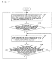
- Fig. 3 is a flowchart showing the operation of the controller in the refrigeration apparatus according to Embodiment 1.
- the controller 61 activates the high-temperature side compressor 12 and the low-temperature side compressor 22, and controls the opening degree of the low-temperature side expansion valve 43, so as to reduce the opening degree the closer the temperature detected by the temperature sensor 62 is to a target temperature.
- the controller 61 determines whether the pressure detected by the low-temperature side low pressure sensor 64 is equal to or lower than a predetermined lower-limit pressure (hereinafter, first predetermined lower-limit pressure).
- the first predetermined lower-limit pressure corresponds to the "third reference pressure" in the present invention.
- the controller 61 returns to step 31.
- step 33 the controller 61 proceeds to step 33.
- the controller 61 turns off the low-temperature side compressor 22, and turns on the high-temperature side compressor 12.
- the controller 61 determines whether the pressure detected by the low-temperature side low pressure sensor 64 is higher than another predetermined lower-limit pressure (hereinafter, second predetermined lower-limit pressure), and whether the pressure detected by the low-temperature side high pressure sensor 63 is equal to or lower than a predetermined upper-limit pressure (hereinafter, first predetermined upper-limit pressure).
- second predetermined lower-limit pressure another predetermined lower-limit pressure
- first predetermined upper-limit pressure hereinafter, first predetermined upper-limit pressure
- the second predetermined lower-limit pressure corresponds to the "first reference pressure" in the present invention.
- the first predetermined upper-limit pressure corresponds to the "second reference pressure" in the present invention.
- the controller 61 returns to step 33.
- step 31 the controller 61 proceeds to step 31.
- the second predetermined lower-limit pressure of step 34 may be the same as or different from the first predetermined lower-limit pressure of step 32.
- the first predetermined upper-limit pressure may be, for example, 6.9 MPa.
- a refrigerant of a low critical temperature such as a CO 2 refrigerant
- the refrigeration apparatus 1 is installed in an environment where outside air temperature is higher than the critical temperature
- the refrigerant in the low-temperature side cycle 21 is heated by the outside air and turns into gas phase when the circulation in the low-temperature side cycle 21 is stopped, and therefore the pressure in the low-temperature side cycle 21 increases.
- the critical temperature of the CO 2 refrigerant is approximately 31 degrees Celsius.
- the controller 61 turns on the high-temperature side compressor 12 when the circulation in the low-temperature side cycle 21 is stopped, to thereby activate the circulation in the high-temperature side cycle 11.
- the gas phase refrigerant in the low-temperature side cycle 21 is condensed and liquefied in the cascade condenser 51 by the refrigerant in the high-temperature side cycle 11, and turns into liquid phase refrigerant.
- the receiver 25 and the cascade condenser 51 have the same pressure, and therefore the liquid phase refrigerant drops onto the receiver 25 located under the cascade condenser 51 b through the pipe 29, because of the gravity.
- the receiver 25 since the receiver 25 is located under the cascade condenser 51, the refrigerant in the low-temperature side cycle 21 condensed and liquefied by the refrigerant in the high-temperature side cycle 11 is promptly collected in the receiver 25 when the circulation in the low-temperature side cycle 21 is stopped, and therefore an increase in pressure in the low-temperature side cycle 21 can be suppressed.
- the controller 61 simply turns on the high-temperature side compressor 12 when the circulation in the low-temperature side cycle 21 is stopped.
- the controller 61 may operate the high-temperature side compressor 12 while controlling at least one of the frequency thereof and the opening degree of the high-temperature side expansion valve 14, on the basis of the pressure detected by the low-temperature side high pressure sensor 63.
- Fig. 4 is a flowchart showing a variation of the operation of the controller in the refrigeration apparatus according to Embodiment 1.
- controller 61 works as shown in Fig. 4 .
- Steps 41, 42, and 44 are the same as steps 31, 32, and 34 in Fig. 3 .
- the controller 61 turns off the low-temperature side compressor 22, and operates the high-temperature side compressor 12 at a higher frequency while reducing the opening degree of the high-temperature side expansion valve 14, the higher the pressure detected by the low-temperature side high pressure sensor 63 is.
- At least one of the frequency of the high-temperature side compressor 12 and the opening degree of the high-temperature side expansion valve 14 may be controlled either linearly or stepwise, on the basis of the pressure detected by the low-temperature side high pressure sensor 63.
- the controller 61 may activate the high-temperature side compressor 12 only when the pressure detected by the low-temperature side high pressure sensor 63 is higher than a predetermined upper-limit pressure (hereinafter, second predetermined upper-limit pressure), at step 33 or strep 43.
- a predetermined upper-limit pressure hereinafter, second predetermined upper-limit pressure
- the second predetermined upper-limit pressure specified for the mentioned case may be the same as or different from the first predetermined upper-limit pressure of step 34 or step 44.
- the controller 61 may activate the high-temperature side compressor 12 only when a predetermined time (hereinafter, first predetermined time) has elapsed after the circulation in the low-temperature side cycle 21 is stopped.
- the controller 61 may operate the high-temperature side compressor 12 either continuously or intermittently, when the first predetermined time has elapsed after the circulation in the low-temperature side cycle 21 is stopped.
- controller 61 may monitor, based on the pressure detected by the low-temperature side high pressure sensor 63, whether the pressure in the low-temperature side cycle 21 has dropped, in other words whether the refrigerant is falling onto the receiver 25, at step 33 or step 43.
- the controller 61 determines that the refrigerant is not falling onto the receiver 25 in the mentioned case, the controller 61 outputs an alarm signal.
- a non-illustrated temperature sensor may be provided in the receiver 25, and the controller 61 may determine whether the refrigerant is falling onto the receiver 25 on the basis of the temperature detected by the temperature sensor.
- the cascade condenser 51 of the refrigeration apparatus according to Embodiment 1 includes a pair of plate-type heat exchangers connected in series and disposed side by side as shown in Fig. 2
- the cascade condenser 51 may be configured in a different form.
- the cascade condenser 51 may be a shell-and-tube heat exchanger, without limitation to the plate-type heat exchanger.
- the cascade condenser 51 may be constituted of a single heat exchanger, or three or more heat exchangers disposed side by side.
- the cascade condenser 51 may include a plurality of heat exchangers connected in parallel, or a plurality of heat exchangers aligned in a vertical direction.
- Fig. 5 is a perspective view showing a variation of the cascade condenser in the refrigeration apparatus according to Embodiment 1.
- the refrigerant in the low-temperature side cycle 21, which has been condensed and liquefied in the high-temperature side evaporator 15, can smoothly flow downward because of the gravity, thereby more effectively suppressing the increase in pressure in the low-temperature side cycle 21.
- Fig. 6 is a diagram showing the configuration of the refrigeration apparatus according to Embodiment 2.
- the refrigeration apparatus 2 includes the high-temperature side cycle 11, a low-temperature side cycle 30, the cascade condenser 51, and a controller 65.
- the low-temperature side cycle 30 includes a low-temperature side compressor 22, the intermediate cooler 23, the low-temperature side condenser 24, the receiver 25, the cooling unit 41, and the accumulator 26.
- a flow control valve 31 is provided between the outlet side of the low-temperature side condenser 24 and the inlet side of the receiver 25.
- At least the high-temperature side compressor 12, the low-temperature side compressor 22, the flow control valve 31, the low-temperature side expansion valve 43, the temperature sensor 62, the low-temperature side high pressure sensor 63, and the low-temperature side low pressure sensor 64 are connected to the controller 65.
- Fig. 7 is a flowchart showing the operation of the controller in the refrigeration apparatus according to Embodiment 2.
- the controller 65 works as shown in Fig. 7 .
- Steps 71, 72, and 74 are the same as steps 31, 32, and 34 in Fig. 3 .
- the controller 65 turns off the low-temperature side compressor 22 and turns on the high-temperature side compressor 12 while opening the flow control valve 31.
- the controller 65 may open the flow control valve 31 to a fixed opening degree.
- the controller 65 may open the flow control valve 31 to the higher opening degree, the higher the pressure detected by the low-temperature side high pressure sensor 63 is, at step 73.
- the opening degree of the flow control valve 31 may be adjusted either linearly or stepwise, on the basis of the pressure detected by the low-temperature side high pressure sensor 63.
- the controller 65 may open the flow control valve 31 to the fixed opening degree or to the opening degree based on the pressure detected by the low-temperature side high pressure sensor 63, only when the pressure detected by the low-temperature side high pressure sensor 63 is higher than a predetermined upper-limit pressure (hereinafter, third predetermined upper-limit pressure).
- a predetermined upper-limit pressure hereinafter, third predetermined upper-limit pressure
- the third predetermined upper-limit pressure specified for the mentioned case may be the same as or different from the first predetermined upper-limit pressure of step 74.
- the controller 65 may open the flow control valve 31 only when a predetermined time (hereinafter, second predetermined time) has elapsed after the circulation in the low-temperature side cycle 30 is stopped.
- the controller 65 may open the flow control valve 31 either continuously or intermittently, when the second predetermined time has elapsed after the circulation in the low-temperature side cycle 30 is stopped.
- the controller 65 activates the high-temperature side compressor 12 while opening the flow control valve 31, when the circulation of the refrigerant in the low-temperature side cycle 30 is stopped.
- the refrigerant can more smoothly fall onto the receiver 25 from the low-temperature side condenser 24, and hence the refrigerant condensed and liquefied by the refrigerant in the high-temperature side cycle 11 is more rapidly collected into the receiver 25. Consequently, the increase in pressure in the low-temperature side cycle 30 can be more effectively suppressed.
- controller 65 controls the opening and closing of the flow control valve 31 in the refrigeration apparatus according to Embodiment 2
- the flow control valve 31 may be manually opened and closed.
- the controller 65 simply turns on the high-temperature side compressor 12 when the circulation in the low-temperature side cycle 30 is stopped.
- the controller 65 may operate the high-temperature side compressor 12 while controlling at least one of the frequency thereof and the opening degree of the high-temperature side expansion valve 14, on the basis of the pressure detected by the low-temperature side high pressure sensor 63, as shown in Fig. 4 .
- Fig. 8 is a diagram showing the configuration of the refrigeration apparatus according to Embodiment 3.
- the refrigeration apparatus 3 includes the high-temperature side cycle 11, a low-temperature side cycle 32, the cascade condenser 51, and a controller 66.
- the low-temperature side cycle 32 includes the low-temperature side compressor 22, the intermediate cooler 23, the low-temperature side condenser 24, the receiver 25, the cooling unit 41, and the accumulator 26.
- the top portion of the receiver 25 and the inlet side of the low-temperature side condenser 24 are connected to each other via a bypass pipe 33.
- the bypass pipe 33 includes a low-temperature side second solenoid valve 34.
- At least the high-temperature side compressor 12, the low-temperature side compressor 22, the low-temperature side second solenoid valve 34, the low-temperature side expansion valve 43, the temperature sensor 62, the low-temperature side high pressure sensor 63, and the low-temperature side low pressure sensor 64 are connected to the controller 66.
- Fig. 9 is a flowchart showing the operation of the controller in the refrigeration apparatus according to Embodiment 3.
- the controller 66 works as shown in Fig. 9 .
- Steps 91, 92, and 94 are the same as steps 31, 32, and 34 in Fig. 3 .
- the controller 66 turns off the low-temperature side compressor 22 and turns on the high-temperature side compressor 12 while opening the low-temperature side second solenoid valve 34.
- the controller 66 may open the low-temperature side second solenoid valve 34, only when the pressure detected by the low-temperature side high pressure sensor 63 is higher than a predetermined upper-limit pressure (hereinafter, fourth predetermined upper-limit pressure).
- the fourth predetermined upper-limit pressure specified for the mentioned case may be the same as or different from the first predetermined upper-limit pressure of step 94.
- the controller 66 may open the low-temperature side second solenoid valve 34 only when a predetermined time (hereinafter, third predetermined time) has elapsed after the circulation in the low-temperature side cycle 32 is stopped.
- a predetermined time hereinafter, third predetermined time
- the controller 66 may open the low-temperature side second solenoid valve 34 either continuously or intermittently, when the third predetermined time has elapsed after the circulation in the low-temperature side cycle 32 is stopped.
- the controller 66 activates the high-temperature side compressor 12 while opening the low-temperature side second solenoid valve 34, when the circulation of the refrigerant in the low-temperature side cycle 32 is stopped.
- the refrigerant turned into gas phase is conducted to the low-temperature side condenser 24 through the bypass pipe 33, and hence the refrigerant condensed and liquefied by the refrigerant in the high-temperature side cycle 11 can more smoothly fall from the low-temperature side condenser 24 onto the receiver 25. Consequently, the increase in pressure in the low-temperature side cycle 32 can be more effectively suppressed.
- the controller 66 controls the opening and closing of the low-temperature side second solenoid valve 34 in the refrigeration apparatus according to Embodiment 3, the valve may be provided in the bypass pipe 33 and manually opened and closed.
- the controller 66 simply turns on the high-temperature side compressor 12 when the circulation in the low-temperature side cycle 32 is stopped.
- controller 66 may operate the high-temperature side compressor 12 while controlling at least one of the frequency thereof and the opening degree of the high-temperature side expansion valve 14, on the basis of the pressure detected by the low-temperature side high pressure sensor 63, as shown in Fig. 4 .
- the flow control valve 31 may be provided between the outlet side of the low-temperature side condenser 24 and the inlet side of the receiver 25, as in the refrigeration apparatus according to Embodiment 2.
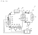
- Fig. 10 is a diagram showing the configuration of the refrigeration apparatus according to Embodiment 4.
- the refrigeration apparatus 4 includes a high-temperature side cycle 16, the low-temperature side cycle 21, the cascade condenser 51, and a controller 67.
- the high-temperature side cycle 16 includes the high-temperature side compressor 12, the high-temperature side condenser 13, the high-temperature side expansion valve 14, and the high-temperature side evaporator 15.
- a service valve 17 is provided between the outlet side of the high-temperature side expansion valve 14 and the inlet side of the high-temperature side evaporator 15.
- a service valve 18 is provided between the outlet side of the high-temperature side evaporator 15 and the inlet side of the high-temperature side compressor 12.
- the low-temperature side cycle 21 and the cascade condenser 51 can be separated from the refrigeration apparatus 4, by the service valves 17 and 18.
- the controller 67 includes a high-temperature side controller 68 and a low-temperature side controller 69.
- Fig. 11 is a drawing showing an arrangement of the components in the refrigeration apparatus according to Embodiment 4.
- the components of the refrigeration apparatus 4 are separately located in a high-temperature side casing 81 and a low-temperature side casing 82.
- Fig. 11 illustrates the case where the cooling unit 41 is separated.
- the high-temperature side casing 81 includes the high-temperature side compressor 12, the high-temperature side condenser 13, the high-temperature side expansion valve 14, and the high-temperature side controller 68.
- the low-temperature side casing 82 includes the low-temperature side compressor 22, the intermediate cooler 23, the receiver 25, the accumulator 26, the cascade condenser 51, and the low-temperature side controller 69.
- the high-temperature side casing 81 and the low-temperature side casing 82 are mounted on a pedestal 83.
- Forming the high-temperature side casing 81 and the low-temperature side casing 82 in the same shape enables the parts to be used in common, thereby contributing to reducing the cost of the refrigeration apparatus.
- the service valves 17 and 18 are located in the high-temperature side casing 81.
- the service valves 27 and 28 are located in the high-temperature side casing 82.
- the high-temperature side controller 68 includes an operation switch 70.
- At least the high-temperature side compressor 12, and an air-blowing device 84 that supplies outside air to the high-temperature side condenser 13 are connected to the high-temperature side controller 68.
- the low-temperature side controller 69 includes an operation switch 71.
- At least the low-temperature side compressor 22, the low-temperature side expansion valve 43, the temperature sensor 62, the low-temperature side high pressure sensor 63, the low-temperature side low pressure sensor 64, and an air-blowing device 85 that supplies outside air to the intermediate cooler 23 are connected to the low-temperature side controller 69.
- the components are separately located in the high-temperature side casing 81 and the low-temperature side casing 82.
- Such a configuration reduces the weight of each of the casings compared with the case where all the components are included in a single casing, thereby facilitating the transport and installment of the refrigeration apparatus 4.
- cascade condenser 51 is located in the low-temperature side casing 82.
- the low-temperature side casing 82 can be additionally connected on site to an existing refrigeration apparatus that includes a compressor, a condenser, and an expansion valve like the high-temperature side casing 81, and therefore the existing refrigeration apparatus can be easily converted into a plural refrigeration apparatus.
- the high-temperature side casing 81 and the low-temperature side casing 82 respectively include the high-temperature side controller 68 and the low-temperature side controller 69.
- the operator can turn on the operation switch 71 provided in the low-temperature side casing 82 thereby cooling an object to be cooled, such as the air in the refrigerating room.
- the service valve 17 is provided between the outlet side of the high-temperature side expansion valve 14 and the inlet side of the high-temperature side evaporator 15.
- the service valve 17 may be provided between the outlet side of the high-temperature side condenser 13 and the inlet side of the high-temperature side expansion valve 14, and the high-temperature side expansion valve 14 may be located in the low-temperature side casing 82.
- the cascade condenser 51 is located in the low-temperature side casing 82 in the refrigeration apparatus according to Embodiment 4, the service valves 17 and 18 may be provided in the low-temperature side cycle 21 and the cascade condenser 51 may be located in the high-temperature side casing 81.
- the pipes of the high-temperature side casing 81 and the pipe of the low-temperature side casing 82 are connected via the service valves 17 and 18 in the refrigeration apparatus according to Embodiment 4, the pipes may be connected by a different method, for example by brazing, instead of via the service valves 17 and 18.
- Embodiment 1 to Embodiment 4 have been described as above, the present invention is in no way limited to those Embodiments.
Landscapes
- Engineering & Computer Science (AREA)
- Physics & Mathematics (AREA)
- Mechanical Engineering (AREA)
- Thermal Sciences (AREA)
- General Engineering & Computer Science (AREA)
- Devices That Are Associated With Refrigeration Equipment (AREA)
Abstract
Description
- The present invention relates to a refrigeration apparatus including a plurality of refrigeration cycles (refrigerant circuits), and a control method of such a refrigeration apparatus.
- Some of existing refrigeration apparatuses include a high-temperature side (or higher side, primary side) refrigeration cycle (hereinafter, high-temperature side cycle) and a low-temperature side (or lower side, secondary side) refrigeration cycle (hereinafter, low-temperature side cycle) (for example, see Patent Literature 1).
- In such refrigeration apparatuses, an evaporator in the high-temperature side cycle and a condenser in the low-temperature side cycle constitute a cascade condenser.
- A refrigerant in the high-temperature side cycle and a refrigerant in the low-temperature side cycle exchange heat in the cascade condenser.
- The refrigerant in the low-temperature side cycle and an object to be cooled, such as air in a refrigerating room, exchange heat in the evaporator in the low-temperature side cycle.
- Patent Literature 1: Japanese Unexamined Patent Application Publication No.
2012-112615 Fig. 1 to Fig. 7 ) - In the refrigeration apparatus thus configured, when a refrigeration load in the low-temperature side cycle decreases the controller drives an expansion valve in the low-temperature side cycle so as to narrow the path, thereby reducing the refrigerant supply to a compressor in the low-temperature side cycle.
- When the refrigeration load in the low-temperature side cycle decreases further after the refrigerant supply to the compressor in the low-temperature side cycle reaches the minimum level, the controller turns off the compressor in the low-temperature side cycle, in other words stops the circulation in the low-temperature side cycle, to thereby prevent the compressor in the low-temperature side cycle from sucking an excessive amount of the refrigerant, thus preventing a pressure drop in the low-temperature side cycle.
- Such a control is called low-pressure cut-off control.
- In addition, when a malfunction arises, for example, when the compressor in the low-temperature side cycle becomes inoperative, the circulation in the low-temperature side cycle is stopped, as in the low-pressure cut-off control.
- Further, the circulation in the low-temperature side cycle may be stopped as in the low-pressure cut-off control, when the evaporator in the low-temperature side cycle is performing a defrosting operation.
- In such a refrigeration apparatus, a refrigerant of a low critical temperature such as a CO2 refrigerant is often employed as the refrigerant in the low-temperature side cycle.
- When such a refrigeration apparatus is used in an environment where outside air has a higher temperature than the critical temperature of the refrigerant, the refrigerant in the low-temperature side cycle is heated by the outside air thus turning into gas phase when the circulation in the low-temperature side cycle is stopped as above, and therefore the pressure in the low-temperature side cycle increases.
- Accordingly, in the conventional refrigeration apparatuses configured as above, the components constituting the low-temperature side cycle are required to have a rigid structure (for example, a sufficient wall thickness), in order to cope with the pressure increase in the low-temperature side cycle, which inevitably leads to an increase in cost as well as in weight.
- The present invention has been accomplished in view of the foregoing problem, and provides a refrigeration apparatus that suppresses an increase in pressure in a low-temperature side cycle when circulation in the low-temperature side cycle is stopped, and a control method performed by the refrigeration apparatus.
- In an aspect, the present invention provides a refrigeration apparatus includes a first refrigerant circuit in which a refrigerant circulates, the first refrigerant circuit including a first compressor, a first condenser, a first throttle device, and a first evaporator sequentially connected by piping, a second refrigerant circuit in which a refrigerant circulates, the second refrigerant circuit including a second compressor, a second condenser, a receiver, a second throttle device, and a second evaporator sequentially connected by piping, and a cascade condenser including the first evaporator and the second condenser and configured to heat exchange between the refrigerant flowing in the first evaporator and the refrigerant flowing in the second condenser. The receiver is located under the cascade condenser.
- In the refrigeration apparatus according to the present invention, the receiver is located under the cascade condenser. Accordingly, when the circulation in the second refrigerant circuit is stopped, the refrigerant in the second refrigerant circuit, which has been condensed and liquefied by the refrigerant in the first refrigerant circuit, is rapidly collected in the receiver, and therefore an increase in pressure in the second refrigerant circuit can be suppressed.
-
- [
Fig. 1] Fig. 1 is a diagram showing a configuration of a refrigeration apparatus according toEmbodiment 1 of the present invention. - [
Fig. 2] Fig. 2 is a perspective view showing the refrigeration apparatus according toEmbodiment 1 of the present invention. - [
Fig. 3] Fig. 3 is a flowchart showing an operation of a controller in the refrigeration apparatus according toEmbodiment 1 of the present invention. - [
Fig. 4] Fig. 4 is a flowchart showing a variation of the operation of the controller in the refrigeration apparatus according toEmbodiment 1 of the present invention. - [
Fig. 5] Fig. 5 is a perspective view showing a variation of a cascade condenser in the refrigeration apparatus according toEmbodiment 1 of the present invention. - [
Fig. 6] Fig. 6 is a diagram showing a configuration of a refrigeration apparatus according toEmbodiment 2 of the present invention. - [
Fig. 7] Fig. 7 is a flowchart showing an operation of a controller in the refrigeration apparatus according toEmbodiment 2 of the present invention. - [
Fig. 8] Fig. 8 is a diagram showing a configuration of a refrigeration apparatus according toEmbodiment 3 of the present invention. - [
Fig. 9] Fig. 9 is a flowchart showing an operation of a controller in the refrigeration apparatus according toEmbodiment 3 of the present invention. - [
Fig. 10] Fig. 10 is a diagram showing a configuration of a refrigeration apparatus according toEmbodiment 4 of the present invention. - [
Fig. 11] Fig. 11 is a drawing showing an arrangement of components in the refrigeration apparatus according toEmbodiment 4 of the present invention. Description of Embodiments - A refrigeration apparatus according to the present invention will be described with reference to the drawings.
- Although the description given hereunder refers to a refrigeration apparatus having two refrigeration cycles (binary refrigeration apparatus), the present invention encompasses refrigeration apparatuses having three or more refrigeration cycles (plural refrigeration apparatus).
- In the drawings, portions of minor importance may be simplified or excluded.
- In addition, duplicate description will be simplified or skipped, as the case may be.
- Hereunder, a refrigeration apparatus according to
Embodiment 1 will be described. - The description given below refers to the case where circulation in a low-temperature side cycle is stopped under a low-pressure cut-off control, however the present invention also encompasses the case where the circulation in the low-temperature side cycle is stopped for another reason than the low-pressure cut-off control, such as a failure of a compressor in the low-temperature side cycle or defrosting operation of an evaporator in the low-temperature side cycle.
- The configuration of the refrigeration apparatus according to
Embodiment 1 will be described hereunder. -
Fig. 1 is a diagram showing the configuration of the refrigeration apparatus according toEmbodiment 1 of the present invention. - As shown in
Fig. 1 , therefrigeration apparatus 1 includes a high-temperature side cycle 11, a low-temperature side cycle 21, acascade condenser 51, and acontroller 61. - The high-
temperature side cycle 11 corresponds to the "first refrigerant circuit" in the present invention. - The low-
temperature side cycle 21 corresponds to the "second refrigerant circuit" in the present invention. - The high-
temperature side cycle 11 includes a high-temperature side compressor 12, a high-temperature side condenser 13, a high-temperatureside expansion valve 14, and a high-temperature side evaporator 15. - The high-
temperature side compressor 12 corresponds to the "first compressor" in the present invention. - The high-
temperature side condenser 13 corresponds to the "first condenser" in the present invention. - The high-temperature
side expansion valve 14 corresponds to the "first throttle device" in the present invention. - The high-
temperature side evaporator 15 corresponds to the "first evaporator" in the present invention. - The high-
temperature side compressor 12, the high-temperature side condenser 13, the high-temperatureside expansion valve 14, and the high-temperature side evaporator 15 are connected in series. - The low-
temperature side cycle 21 includes a low-temperature side compressor 22, anintermediate cooler 23, a low-temperature side condenser 24, areceiver 25, acooling unit 41, and anaccumulator 26. - The low-
temperature side compressor 22 corresponds to the "second compressor" in the present invention. - The low-
temperature side condenser 24 corresponds to the "second condenser" in the present invention. - The low-
temperature side compressor 22, theintermediate cooler 23, the low-temperature side condenser 24, thereceiver 25, thecooling unit 41, and theaccumulator 26 are connected in series. - A
service valve 27 is provided between the outlet side of thereceiver 25 and the inlet side of thecooling unit 41. - A
service valve 28 is provided between the outlet side of thecooling unit 41 and the inlet side of theaccumulator 26. - The
cooling unit 41 can be separated from therefrigeration apparatus 1 by theservice valves - The
service valves cooling unit 41 may be inseparable. - Here, a non-illustrated sight glass for confirming the amount or condition of the refrigerant, and a non-illustrated drier for absorbing moisture in the pipe may be provided in the low-
temperature side cycle 21. - The high-
temperature side evaporator 15 and the low-temperature side condenser 24 constitute acascade condenser 51. - The refrigerant in the high-
temperature side cycle 11 and the refrigerant in the low-temperature side cycle 21 exchange heat with each other in thecascade condenser 51. -
Fig. 2 is a perspective view showing the refrigeration apparatus according toEmbodiment 1. - As shown in
Fig. 2 , thereceiver 25 is located under thecascade condenser 51. - The
receiver 25 and the low-temperature side condenser 24 are connected to each other via apipe 29 having an outer diameter of, for example, 15.88 mm. -
Fig. 2 illustrates the case where thecascade condenser 51 is composed of a pair of plate-type heat exchangers connected in series and disposed side by side. - In addition,
Fig. 2 illustrates the case where the coolingunit 41 is separated. - The cooling
unit 41 includes a low-temperature sidefirst solenoid valve 42, a low-temperatureside expansion valve 43, and a low-temperature side evaporator 44. - The low-temperature
side expansion valve 43 corresponds to the "second throttle device" in the present invention. - The low-
temperature side evaporator 44 corresponds to the "second evaporator" in the present invention. - The low-temperature side
first solenoid valve 42, the low-temperatureside expansion valve 43, and the low-temperature side evaporator 44 are connected in series. - The low-
temperature side evaporator 44 is located in a refrigerating room. - Examples of the refrigerating room include a freezing showcase installed in a super market or the like, and a freezing room of a unit cooler installed in a food processing plant.
- A cooling unit utilized in an existing refrigerating room may be employed as the cooling
unit 41. - As the refrigerant in the high-
temperature side cycle 11, for example a HFC refrigerant (R410A, R404A, R32, R407C), a HFO refrigerant, or a HC refrigerant may be employed. - As the refrigerant in the low-
temperature side cycle 21, for example a CO2 refrigerant having a global warming potential (GWP) of 1 may be employed. - At least the high-
temperature side compressor 12, the low-temperature side compressor 22, the low-temperatureside expansion valve 43, thetemperature sensor 62, the low-temperature sidehigh pressure sensor 63, and the low-temperature sidelow pressure sensor 64 are connected to thecontroller 61. - The
temperature sensor 62 detects the temperature of the object to be cooled, such as the air in the refrigerating room. - The low-temperature side
high pressure sensor 63 is located, for example, between the outlet side of theintermediate cooler 23 and the inlet side of the low-temperature side condenser 24, and detects the pressure on the high-pressure side of the low-temperature side cycle 21. - The low-temperature side
high pressure sensor 63 may be located at a desired position, provided that the position is between the outlet side of the low-temperature side compressor 22 and the inlet side of the low-temperatureside expansion valve 43. - The low-temperature side
low pressure sensor 64 is located, for example, between theservice valve 28 and the inlet side of theaccumulator 26, and detects the pressure on the low-pressure side of the low-temperature side cycle 21. - The low-temperature side
low pressure sensor 64 may be located at a desired position, provided that the position is between the outlet side of the low-temperatureside expansion valve 43 and the inlet side of the low-temperature side compressor 22. - The operation of the refrigeration apparatus according to
Embodiment 1 will be described hereunder. - First, the operation of the high-
temperature side cycle 11 will be described. - High-temperature/high-pressure gas phase refrigerant discharged from the high-
temperature side compressor 12 flows into the high-temperature side condenser 13. - The refrigerant which has entered the high-
temperature side condenser 13 is condensed and liquefied through heat exchange with outside air, and turns into high-pressure liquid phase refrigerant. - The high-pressure liquid phase refrigerant is depressurized in the high-temperature
side expansion valve 14, thus to turn into low-temperature/low-pressure gas-liquid two-phase refrigerant. - The low-temperature/low-pressure gas-liquid two-phase refrigerant is heated in the
cascade condenser 51 by the refrigerant in the low-temperature side cycle 21 (cools the refrigerant in the low-temperature side cycle 21) and evaporated, thus to turn into low-pressure gas phase refrigerant. - The low-pressure gas phase refrigerant flows into the high-
temperature side compressor 12. - The operation of the low-
temperature side cycle 21 will now be described. - High-temperature/high-pressure gas phase refrigerant discharged from the low-
temperature side compressor 22 is cooled in theintermediate cooler 23 and flows into thecascade condenser 51. - The refrigerant which has entered the
cascade condenser 51 is condensed and liquefied by the refrigerant in the high-temperature side cycle 11, and turns into high-pressure liquid phase refrigerant. - The high-pressure liquid phase refrigerant flows into the low-temperature
side expansion valve 43 through thereceiver 25, theservice valve 27, and the low-temperature sidefirst solenoid valve 42. - The high-pressure liquid phase refrigerant which has entered the low-temperature
side expansion valve 43 is depressurized, thus to turn into low-temperature/low-pressure gas-liquid two-phase refrigerant. - The low-temperature/low-pressure gas-liquid two-phase refrigerant is heated in the low-temperature side evaporator 44 by the air in the refrigerating room (cools the air in the refrigerating room) and evaporated, thus to turn into low-pressure gas phase refrigerant.
- The low-pressure gas phase refrigerant flows into the low-
temperature side compressor 22 through theservice valve 28 and theaccumulator 26. - The operation of the
controller 61 will be described hereunder. - The following is merely an example of the operation of the
controller 61, and the present invention encompasses other operations of thecontroller 61. -
Fig. 3 is a flowchart showing the operation of the controller in the refrigeration apparatus according toEmbodiment 1. - At
step 31, thecontroller 61 activates the high-temperature side compressor 12 and the low-temperature side compressor 22, and controls the opening degree of the low-temperatureside expansion valve 43, so as to reduce the opening degree the closer the temperature detected by thetemperature sensor 62 is to a target temperature. - At
step 32, thecontroller 61 determines whether the pressure detected by the low-temperature sidelow pressure sensor 64 is equal to or lower than a predetermined lower-limit pressure (hereinafter, first predetermined lower-limit pressure). - The first predetermined lower-limit pressure corresponds to the "third reference pressure" in the present invention.
- In the case of No, the
controller 61 returns to step 31. - In the case of Yes, the
controller 61 proceeds to step 33. - At
step 33, thecontroller 61 turns off the low-temperature side compressor 22, and turns on the high-temperature side compressor 12. - At
step 34, thecontroller 61 determines whether the pressure detected by the low-temperature sidelow pressure sensor 64 is higher than another predetermined lower-limit pressure (hereinafter, second predetermined lower-limit pressure), and whether the pressure detected by the low-temperature sidehigh pressure sensor 63 is equal to or lower than a predetermined upper-limit pressure (hereinafter, first predetermined upper-limit pressure). - The second predetermined lower-limit pressure corresponds to the "first reference pressure" in the present invention.
- The first predetermined upper-limit pressure corresponds to the "second reference pressure" in the present invention.
- In the case of No, the
controller 61 returns to step 33. - In the case of Yes, the
controller 61 proceeds to step 31. - The second predetermined lower-limit pressure of
step 34 may be the same as or different from the first predetermined lower-limit pressure ofstep 32. - The first predetermined upper-limit pressure may be, for example, 6.9 MPa.
- When the circulation in the low-
temperature side cycle 21 is stopped for another reason than the low-pressure cut-off control, for example because of a failure of the low-temperature side compressor 22 or defrosting operation by the low-temperature side evaporator 44, the foregoing steps other thanstep 33 are skipped. - The operation of the refrigeration apparatus according to
Embodiment 1 will be described hereunder. - In the case where a refrigerant of a low critical temperature such as a CO2 refrigerant is employed in the low-
temperature side cycle 21, and therefrigeration apparatus 1 is installed in an environment where outside air temperature is higher than the critical temperature, the refrigerant in the low-temperature side cycle 21 is heated by the outside air and turns into gas phase when the circulation in the low-temperature side cycle 21 is stopped, and therefore the pressure in the low-temperature side cycle 21 increases. - Here, the critical temperature of the CO2 refrigerant is approximately 31 degrees Celsius.
- In the refrigeration apparatus according to
Embodiment 1, thecontroller 61 turns on the high-temperature side compressor 12 when the circulation in the low-temperature side cycle 21 is stopped, to thereby activate the circulation in the high-temperature side cycle 11. - Accordingly, the gas phase refrigerant in the low-
temperature side cycle 21 is condensed and liquefied in thecascade condenser 51 by the refrigerant in the high-temperature side cycle 11, and turns into liquid phase refrigerant. - The
receiver 25 and thecascade condenser 51 have the same pressure, and therefore the liquid phase refrigerant drops onto thereceiver 25 located under the cascade condenser 51 b through thepipe 29, because of the gravity. - Thus, in the refrigeration apparatus according to
Embodiment 1, since thereceiver 25 is located under thecascade condenser 51, the refrigerant in the low-temperature side cycle 21 condensed and liquefied by the refrigerant in the high-temperature side cycle 11 is promptly collected in thereceiver 25 when the circulation in the low-temperature side cycle 21 is stopped, and therefore an increase in pressure in the low-temperature side cycle 21 can be suppressed. - Consequently, the cost as well as the weight of the components constituting the low-
temperature side cycle 21 can be reduced. - In the refrigeration apparatus according to
Embodiment 1, thecontroller 61 simply turns on the high-temperature side compressor 12 when the circulation in the low-temperature side cycle 21 is stopped. - Alternatively, the
controller 61 may operate the high-temperature side compressor 12 while controlling at least one of the frequency thereof and the opening degree of the high-temperatureside expansion valve 14, on the basis of the pressure detected by the low-temperature sidehigh pressure sensor 63. -
Fig. 4 is a flowchart showing a variation of the operation of the controller in the refrigeration apparatus according toEmbodiment 1. - In the aforementioned case, the
controller 61 works as shown inFig. 4 . -
Steps steps Fig. 3 . - At
step 43, thecontroller 61 turns off the low-temperature side compressor 22, and operates the high-temperature side compressor 12 at a higher frequency while reducing the opening degree of the high-temperatureside expansion valve 14, the higher the pressure detected by the low-temperature sidehigh pressure sensor 63 is. - At least one of the frequency of the high-
temperature side compressor 12 and the opening degree of the high-temperatureside expansion valve 14 may be controlled either linearly or stepwise, on the basis of the pressure detected by the low-temperature sidehigh pressure sensor 63. - The
controller 61 may activate the high-temperature side compressor 12 only when the pressure detected by the low-temperature sidehigh pressure sensor 63 is higher than a predetermined upper-limit pressure (hereinafter, second predetermined upper-limit pressure), atstep 33 orstrep 43. - The second predetermined upper-limit pressure specified for the mentioned case may be the same as or different from the first predetermined upper-limit pressure of
step 34 orstep 44. - At
step 33 orstep 43, thecontroller 61 may activate the high-temperature side compressor 12 only when a predetermined time (hereinafter, first predetermined time) has elapsed after the circulation in the low-temperature side cycle 21 is stopped. - In such a case, the
controller 61 may operate the high-temperature side compressor 12 either continuously or intermittently, when the first predetermined time has elapsed after the circulation in the low-temperature side cycle 21 is stopped. - Further, the
controller 61 may monitor, based on the pressure detected by the low-temperature sidehigh pressure sensor 63, whether the pressure in the low-temperature side cycle 21 has dropped, in other words whether the refrigerant is falling onto thereceiver 25, atstep 33 orstep 43. - When the
controller 61 determines that the refrigerant is not falling onto thereceiver 25 in the mentioned case, thecontroller 61 outputs an alarm signal. - Alternatively, a non-illustrated temperature sensor may be provided in the
receiver 25, and thecontroller 61 may determine whether the refrigerant is falling onto thereceiver 25 on the basis of the temperature detected by the temperature sensor. - Although the
cascade condenser 51 of the refrigeration apparatus according toEmbodiment 1 includes a pair of plate-type heat exchangers connected in series and disposed side by side as shown inFig. 2 , thecascade condenser 51 may be configured in a different form. - The
cascade condenser 51 may be a shell-and-tube heat exchanger, without limitation to the plate-type heat exchanger. - The
cascade condenser 51 may be constituted of a single heat exchanger, or three or more heat exchangers disposed side by side. - The
cascade condenser 51 may include a plurality of heat exchangers connected in parallel, or a plurality of heat exchangers aligned in a vertical direction. -
Fig. 5 is a perspective view showing a variation of the cascade condenser in the refrigeration apparatus according toEmbodiment 1. - In the case where a plurality of heat exchangers are aligned in the vertical direction as shown in
Fig. 5 , the refrigerant in the low-temperature side cycle 21, which has been condensed and liquefied in the high-temperature side evaporator 15, can smoothly flow downward because of the gravity, thereby more effectively suppressing the increase in pressure in the low-temperature side cycle 21. - Hereunder, the refrigeration apparatus according to
Embodiment 2 will be described. - The description of the same aspects as those of the refrigeration apparatus according to
Embodiment 1 will be simplified or skipped, as the case may be. - The configuration of the refrigeration apparatus according to
Embodiment 2 will be described hereunder. -
Fig. 6 is a diagram showing the configuration of the refrigeration apparatus according toEmbodiment 2. - As shown in
Fig. 6 , therefrigeration apparatus 2 includes the high-temperature side cycle 11, a low-temperature side cycle 30, thecascade condenser 51, and acontroller 65. - The low-
temperature side cycle 30 includes a low-temperature side compressor 22, theintermediate cooler 23, the low-temperature side condenser 24, thereceiver 25, the coolingunit 41, and theaccumulator 26. - A
flow control valve 31 is provided between the outlet side of the low-temperature side condenser 24 and the inlet side of thereceiver 25. - At least the high-
temperature side compressor 12, the low-temperature side compressor 22, theflow control valve 31, the low-temperatureside expansion valve 43, thetemperature sensor 62, the low-temperature sidehigh pressure sensor 63, and the low-temperature sidelow pressure sensor 64 are connected to thecontroller 65. - The operation of the refrigeration apparatus according to
Embodiment 2 will be described hereunder. -
Fig. 7 is a flowchart showing the operation of the controller in the refrigeration apparatus according toEmbodiment 2. - The
controller 65 works as shown inFig. 7 . -
Steps steps Fig. 3 . - At step 73, the
controller 65 turns off the low-temperature side compressor 22 and turns on the high-temperature side compressor 12 while opening theflow control valve 31. - At step 73, the
controller 65 may open theflow control valve 31 to a fixed opening degree. - Alternatively, the
controller 65 may open theflow control valve 31 to the higher opening degree, the higher the pressure detected by the low-temperature sidehigh pressure sensor 63 is, at step 73. - In such a case, the opening degree of the
flow control valve 31 may be adjusted either linearly or stepwise, on the basis of the pressure detected by the low-temperature sidehigh pressure sensor 63. - At step 73, the
controller 65 may open theflow control valve 31 to the fixed opening degree or to the opening degree based on the pressure detected by the low-temperature sidehigh pressure sensor 63, only when the pressure detected by the low-temperature sidehigh pressure sensor 63 is higher than a predetermined upper-limit pressure (hereinafter, third predetermined upper-limit pressure). - The third predetermined upper-limit pressure specified for the mentioned case may be the same as or different from the first predetermined upper-limit pressure of
step 74. - At step 73, the
controller 65 may open theflow control valve 31 only when a predetermined time (hereinafter, second predetermined time) has elapsed after the circulation in the low-temperature side cycle 30 is stopped. - In such a case, the
controller 65 may open theflow control valve 31 either continuously or intermittently, when the second predetermined time has elapsed after the circulation in the low-temperature side cycle 30 is stopped. - The advantageous effects of the refrigeration apparatus according to
Embodiment 2 will be described hereunder. - In the refrigeration apparatus according to
Embodiment 2, thecontroller 65 activates the high-temperature side compressor 12 while opening theflow control valve 31, when the circulation of the refrigerant in the low-temperature side cycle 30 is stopped. - Accordingly, the refrigerant can more smoothly fall onto the
receiver 25 from the low-temperature side condenser 24, and hence the refrigerant condensed and liquefied by the refrigerant in the high-temperature side cycle 11 is more rapidly collected into thereceiver 25. Consequently, the increase in pressure in the low-temperature side cycle 30 can be more effectively suppressed. - Although the
controller 65 controls the opening and closing of theflow control valve 31 in the refrigeration apparatus according toEmbodiment 2, theflow control valve 31 may be manually opened and closed. - In the refrigeration apparatus according to
Embodiment 2, thecontroller 65 simply turns on the high-temperature side compressor 12 when the circulation in the low-temperature side cycle 30 is stopped. - Alternatively, the
controller 65 may operate the high-temperature side compressor 12 while controlling at least one of the frequency thereof and the opening degree of the high-temperatureside expansion valve 14, on the basis of the pressure detected by the low-temperature sidehigh pressure sensor 63, as shown inFig. 4 . - Hereunder, the refrigeration apparatus according to
Embodiment 3 will be described. - The description of the same aspects as those of the refrigeration apparatus according to
Embodiment 1 andEmbodiment 2 will be simplified or skipped, as the case may be. - The configuration of the refrigeration apparatus according to
Embodiment 3 will be described hereunder. -
Fig. 8 is a diagram showing the configuration of the refrigeration apparatus according toEmbodiment 3. - As shown in
Fig. 8 , therefrigeration apparatus 3 includes the high-temperature side cycle 11, a low-temperature side cycle 32, thecascade condenser 51, and acontroller 66. - The low-
temperature side cycle 32 includes the low-temperature side compressor 22, theintermediate cooler 23, the low-temperature side condenser 24, thereceiver 25, the coolingunit 41, and theaccumulator 26. - The top portion of the
receiver 25 and the inlet side of the low-temperature side condenser 24 are connected to each other via abypass pipe 33. - The
bypass pipe 33 includes a low-temperature sidesecond solenoid valve 34. - At least the high-
temperature side compressor 12, the low-temperature side compressor 22, the low-temperature sidesecond solenoid valve 34, the low-temperatureside expansion valve 43, thetemperature sensor 62, the low-temperature sidehigh pressure sensor 63, and the low-temperature sidelow pressure sensor 64 are connected to thecontroller 66. - The operation of the refrigeration apparatus according to
Embodiment 3 will be described hereunder. -
Fig. 9 is a flowchart showing the operation of the controller in the refrigeration apparatus according toEmbodiment 3. - The
controller 66 works as shown inFig. 9 . - Steps 91, 92, and 94 are the same as
steps Fig. 3 . - At step 93, the
controller 66 turns off the low-temperature side compressor 22 and turns on the high-temperature side compressor 12 while opening the low-temperature sidesecond solenoid valve 34. - At step 93, the
controller 66 may open the low-temperature sidesecond solenoid valve 34, only when the pressure detected by the low-temperature sidehigh pressure sensor 63 is higher than a predetermined upper-limit pressure (hereinafter, fourth predetermined upper-limit pressure). - The fourth predetermined upper-limit pressure specified for the mentioned case may be the same as or different from the first predetermined upper-limit pressure of step 94.
- At step 93, the
controller 66 may open the low-temperature sidesecond solenoid valve 34 only when a predetermined time (hereinafter, third predetermined time) has elapsed after the circulation in the low-temperature side cycle 32 is stopped. - In such a case, the
controller 66 may open the low-temperature sidesecond solenoid valve 34 either continuously or intermittently, when the third predetermined time has elapsed after the circulation in the low-temperature side cycle 32 is stopped. - The advantageous effects of the refrigeration apparatus according to
Embodiment 3 will be described hereunder. - In the refrigeration apparatus according to
Embodiment 3, thecontroller 66 activates the high-temperature side compressor 12 while opening the low-temperature sidesecond solenoid valve 34, when the circulation of the refrigerant in the low-temperature side cycle 32 is stopped. - Accordingly, the refrigerant turned into gas phase is conducted to the low-
temperature side condenser 24 through thebypass pipe 33, and hence the refrigerant condensed and liquefied by the refrigerant in the high-temperature side cycle 11 can more smoothly fall from the low-temperature side condenser 24 onto thereceiver 25. Consequently, the increase in pressure in the low-temperature side cycle 32 can be more effectively suppressed. - Although the
controller 66 controls the opening and closing of the low-temperature sidesecond solenoid valve 34 in the refrigeration apparatus according toEmbodiment 3, the valve may be provided in thebypass pipe 33 and manually opened and closed. - In the refrigeration apparatus according to
Embodiment 3, thecontroller 66 simply turns on the high-temperature side compressor 12 when the circulation in the low-temperature side cycle 32 is stopped. - Alternatively, the
controller 66 may operate the high-temperature side compressor 12 while controlling at least one of the frequency thereof and the opening degree of the high-temperatureside expansion valve 14, on the basis of the pressure detected by the low-temperature sidehigh pressure sensor 63, as shown inFig. 4 . - Further, the
flow control valve 31 may be provided between the outlet side of the low-temperature side condenser 24 and the inlet side of thereceiver 25, as in the refrigeration apparatus according toEmbodiment 2. - Hereunder, the refrigeration apparatus according to
Embodiment 4 will be described. - The description of the same aspects as those of the refrigeration apparatus according to
Embodiment 1 toEmbodiment 3 will be simplified or skipped, as the case may be. - The configuration of the refrigeration apparatus according to
Embodiment 4 will be described hereunder. -
Fig. 10 is a diagram showing the configuration of the refrigeration apparatus according toEmbodiment 4. - As shown in
Fig. 10 , therefrigeration apparatus 4 includes a high-temperature side cycle 16, the low-temperature side cycle 21, thecascade condenser 51, and acontroller 67. - The high-
temperature side cycle 16 includes the high-temperature side compressor 12, the high-temperature side condenser 13, the high-temperatureside expansion valve 14, and the high-temperature side evaporator 15. - A
service valve 17 is provided between the outlet side of the high-temperatureside expansion valve 14 and the inlet side of the high-temperature side evaporator 15. - A
service valve 18 is provided between the outlet side of the high-temperature side evaporator 15 and the inlet side of the high-temperature side compressor 12. - The low-
temperature side cycle 21 and thecascade condenser 51 can be separated from therefrigeration apparatus 4, by theservice valves - The
controller 67 includes a high-temperature side controller 68 and a low-temperature side controller 69. -
Fig. 11 is a drawing showing an arrangement of the components in the refrigeration apparatus according toEmbodiment 4. - As shown in
Fig. 11 , the components of therefrigeration apparatus 4 are separately located in a high-temperature side casing 81 and a low-temperature side casing 82. - Here,
Fig. 11 illustrates the case where the coolingunit 41 is separated. - The high-
temperature side casing 81 includes the high-temperature side compressor 12, the high-temperature side condenser 13, the high-temperatureside expansion valve 14, and the high-temperature side controller 68. - The low-
temperature side casing 82 includes the low-temperature side compressor 22, theintermediate cooler 23, thereceiver 25, theaccumulator 26, thecascade condenser 51, and the low-temperature side controller 69. - The high-
temperature side casing 81 and the low-temperature side casing 82 are mounted on apedestal 83. - Forming the high-
temperature side casing 81 and the low-temperature side casing 82 in the same shape enables the parts to be used in common, thereby contributing to reducing the cost of the refrigeration apparatus. - The
service valves temperature side casing 81. - Placing the
service valves temperature side casing 82 improves the operability of the valves. - The
service valves temperature side casing 82. - Placing the
service valves temperature side casing 81 improves the operability of the valves. - Placing the
cascade condenser 51 on the nearer side to the high-temperature side casing 81 allows the pipe connecting between the high-temperature side evaporator 15 and theservice valves - The high-
temperature side controller 68 includes anoperation switch 70. - At least the high-
temperature side compressor 12, and an air-blowingdevice 84 that supplies outside air to the high-temperature side condenser 13 are connected to the high-temperature side controller 68. - The low-
temperature side controller 69 includes anoperation switch 71. - At least the low-
temperature side compressor 22, the low-temperatureside expansion valve 43, thetemperature sensor 62, the low-temperature sidehigh pressure sensor 63, the low-temperature sidelow pressure sensor 64, and an air-blowingdevice 85 that supplies outside air to theintermediate cooler 23 are connected to the low-temperature side controller 69. - The advantageous effects of the refrigeration apparatus according to
Embodiment 4 will be described hereunder. - In the refrigeration apparatus according to
Embodiment 4, the components are separately located in the high-temperature side casing 81 and the low-temperature side casing 82. - Such a configuration reduces the weight of each of the casings compared with the case where all the components are included in a single casing, thereby facilitating the transport and installment of the
refrigeration apparatus 4. - Further, the
cascade condenser 51 is located in the low-temperature side casing 82. - Accordingly, the low-
temperature side casing 82 can be additionally connected on site to an existing refrigeration apparatus that includes a compressor, a condenser, and an expansion valve like the high-temperature side casing 81, and therefore the existing refrigeration apparatus can be easily converted into a plural refrigeration apparatus. - In the refrigeration apparatus according to
Embodiment 4, further, the high-temperature side casing 81 and the low-temperature side casing 82 respectively include the high-temperature side controller 68 and the low-temperature side controller 69. - Accordingly, even when the circulation in the high-
temperature side cycle 16 is stopped, for example because of a failure of the high-temperature side compressor 12 or maintenance work for the high-temperature side cycle 16, the operator can turn on theoperation switch 71 provided in the low-temperature side casing 82 thereby cooling an object to be cooled, such as the air in the refrigerating room. - In the refrigeration apparatus according to
Embodiment 4, theservice valve 17 is provided between the outlet side of the high-temperatureside expansion valve 14 and the inlet side of the high-temperature side evaporator 15. Alternatively, theservice valve 17 may be provided between the outlet side of the high-temperature side condenser 13 and the inlet side of the high-temperatureside expansion valve 14, and the high-temperatureside expansion valve 14 may be located in the low-temperature side casing 82. - Although the
cascade condenser 51 is located in the low-temperature side casing 82 in the refrigeration apparatus according toEmbodiment 4, theservice valves temperature side cycle 21 and thecascade condenser 51 may be located in the high-temperature side casing 81. - Although the pipe of the high-
temperature side casing 81 and the pipe of the low-temperature side casing 82 are connected via theservice valves Embodiment 4, the pipes may be connected by a different method, for example by brazing, instead of via theservice valves - Although
Embodiment 1 toEmbodiment 4 have been described as above, the present invention is in no way limited to those Embodiments. - For example, two or more of Embodiments or variations thereof may be combined as desired.
-
- 1, 2, 3, 4: refrigeration apparatus, 11, 16: high-temperature side cycle, 12: high-temperature side compressor, 13: high-temperature side condenser, 14: high-temperature side expansion valve, 15: high-temperature side evaporator, 17, 18, 27, 28: service valve, 21, 30, 32: low-temperature side cycle, 22: low-temperature side compressor, 23: intermediate cooler, 24: low-temperature side condenser, 25: receiver, 26: accumulator, 29: pipe, 31: flow control valve, 33: bypass pipe, 34: low-temperature side second solenoid valve, 41: cooling unit, 42: low-temperature side first solenoid valve, 43: low-temperature side expansion valve, 44: low-temperature side evaporator, 51: cascade condenser, 61, 65, 66, 67: controller, 62: temperature sensor, 63: low-temperature side high pressure sensor, 64: low-temperature side low pressure sensor, 68: high-temperature side controller, 69: low-temperature side controller, 70, 71: operation switch, 81: high-temperature side casing, 82: low-temperature side casing, 83: pedestal, 84, 85: air-blowing device.
Claims (8)
- A refrigeration apparatus comprising:a first refrigerant circuit in which a refrigerant circulates, the first refrigerant circuit including a first compressor, a first condenser, a first expansion device, and a first evaporator sequentially connected by piping;a second refrigerant circuit in which a refrigerant circulates, the second refrigerant circuit including a second compressor, a second condenser, a receiver, a second expansion device, and a second evaporator sequentially connected by piping; anda cascade condenser including the first evaporator and the second condenser and configured to heat exchange between the refrigerant flowing in the first evaporator and the refrigerant flowing in the second condenser,wherein the receiver is located under the cascade condenser.
- The refrigeration apparatus of claim 1, further comprising a controller that controls operation of the first compressor and the second compressor,
wherein the controller activates the first compressor when the second compressor is off. - The refrigeration apparatus of claim 2,
wherein the controller controls at least one of frequency of the first compressor and an opening degree of the first expansion device on the basis of a pressure on a high-pressure side of the second refrigerant circuit, when the second compressor is off and the first compressor is on. - The refrigeration apparatus of claim 2 or 3,
wherein a flow control valve is provided to a pipe connecting between an outlet side of the second condenser and the receiver, and
the controller opens the flow control valve when the second compressor is off and the first compressor is on. - The refrigeration apparatus of any one of claims 2 to 4,
wherein a top portion of the receiver and an inlet side of the second condenser are connected to each other via a bypass pipe and a solenoid valve, and
wherein the controller opens the solenoid valve when the second compressor is off and the first compressor is on. - The refrigeration apparatus of any one of claims 2 to 5,
wherein the controller activates the first compressor and the second compressor when a pressure on a low-pressure side of the second refrigerant circuit is higher than a first predetermined reference pressure and a pressure on the high-pressure side of the second refrigerant circuit is equal to or lower than a second predetermined reference pressure. - The refrigeration apparatus of any one of claims 2 to 6,
wherein the controller turns off the second compressor when the pressure on the low-pressure side of the second refrigerant circuit is equal to or lower than a third predetermined reference pressure. - A control method of a refrigeration apparatus including a first refrigerant circuit in which a refrigerant circulates, the first refrigerant circuit including a first compressor, a first condenser, a first expansion device, and a first evaporator sequentially connected by piping; a second refrigerant circuit in which a refrigerant circulates, the second refrigerant circuit including a second compressor, a second condenser, a receiver, a second expansion device, and a second evaporator sequentially connected by piping; and a cascade condenser including the first evaporator and the second condenser and configured to heat exchange between the refrigerant flowing in the first evaporator and the refrigerant flowing in the second condenser, the receiver being located under the cascade condenser, the method comprising:activating the first compressor when the second compressor is off.
Applications Claiming Priority (1)
| Application Number | Priority Date | Filing Date | Title |
|---|---|---|---|
| PCT/JP2012/074214 WO2014045400A1 (en) | 2012-09-21 | 2012-09-21 | Refrigeration device and method for controlling same |
Publications (3)
| Publication Number | Publication Date |
|---|---|
| EP2910870A1 true EP2910870A1 (en) | 2015-08-26 |
| EP2910870A4 EP2910870A4 (en) | 2016-07-20 |
| EP2910870B1 EP2910870B1 (en) | 2020-01-01 |
Family
ID=50340753
Family Applications (1)
| Application Number | Title | Priority Date | Filing Date |
|---|---|---|---|
| EP12884923.9A Active EP2910870B1 (en) | 2012-09-21 | 2012-09-21 | Refrigeration device and method for controlling same |
Country Status (3)
| Country | Link |
|---|---|
| EP (1) | EP2910870B1 (en) |
| JP (1) | JP5800994B2 (en) |
| WO (1) | WO2014045400A1 (en) |
Cited By (10)
| Publication number | Priority date | Publication date | Assignee | Title |
|---|---|---|---|---|
| EP3064865A1 (en) * | 2015-03-05 | 2016-09-07 | Rivacold S.R.L. | Pressure controlled multistage cooling plant and control method |
| RU188096U1 (en) * | 2018-12-18 | 2019-03-29 | Акционерное общество "Научно-технический комплекс "Криогенная техника" | Transcritical carbon dioxide refrigeration unit |
| EP3479903A1 (en) * | 2017-11-06 | 2019-05-08 | Sigma Laborzentrifugen GmbH | Centrifuge |
| EP3812668A1 (en) * | 2019-10-24 | 2021-04-28 | M.D. Mechanical Devices Ltd. | Cooling system with controlled biphase mixing of refrigerant and a method for cooling with the cooling system |
| US11293670B2 (en) | 2017-06-23 | 2022-04-05 | Daikin Industries, Ltd. | Chiller with an outdoor unit transferring heat to an indoor unit using carbon dioxide |
| CN115111796A (en) * | 2021-03-18 | 2022-09-27 | 东莞市升微机电设备科技有限公司 | Cascade refrigerating system |
| EP4257894A4 (en) * | 2020-12-01 | 2024-05-29 | Daikin Industries, Ltd. | REFRIGERATION CYCLE SYSTEM |
| US12385675B2 (en) | 2020-05-08 | 2025-08-12 | Daikin Industries, Ltd. | Refrigeration cycle apparatus |
| US12391097B2 (en) | 2015-11-03 | 2025-08-19 | Carrier Corporation | Transport refrigeration system and method of operating |
| TWI898214B (en) * | 2022-06-02 | 2025-09-21 | 日商神鋼壓縮機股份有限公司 | Binary Refrigeration Device |
Families Citing this family (23)
| Publication number | Priority date | Publication date | Assignee | Title |
|---|---|---|---|---|
| JP6160555B2 (en) * | 2014-05-08 | 2017-07-12 | 三菱重工冷熱株式会社 | Capacity control method for compressor of multi-source refrigeration system |
| EP3617612B1 (en) * | 2017-04-25 | 2021-09-01 | Mitsubishi Electric Corporation | Binary refrigeration device |
| JP6937608B2 (en) * | 2017-05-09 | 2021-09-22 | エア・ウォーター株式会社 | Cooling device for superconducting cable and cooling method of superconducting cable using it |
| KR101825636B1 (en) * | 2017-07-06 | 2018-03-22 | 주식회사 이너지테크놀러지스 | Heat pump with cooling, heating, hot water supply |
| US11493244B2 (en) | 2017-12-18 | 2022-11-08 | Daikin Industries, Ltd. | Air-conditioning unit |
| US11441819B2 (en) | 2017-12-18 | 2022-09-13 | Daikin Industries, Ltd. | Refrigeration cycle apparatus |
| US11365335B2 (en) | 2017-12-18 | 2022-06-21 | Daikin Industries, Ltd. | Composition comprising refrigerant, use thereof, refrigerating machine having same, and method for operating said refrigerating machine |
| WO2019123898A1 (en) | 2017-12-18 | 2019-06-27 | ダイキン工業株式会社 | Refrigeration machine oil for refrigerant or refrigerant composition, method for using refrigeration machine oil, and use of refrigeration machine oil |
| US11441802B2 (en) | 2017-12-18 | 2022-09-13 | Daikin Industries, Ltd. | Air conditioning apparatus |
| US11506425B2 (en) | 2017-12-18 | 2022-11-22 | Daikin Industries, Ltd. | Refrigeration cycle apparatus |
| US11820933B2 (en) | 2017-12-18 | 2023-11-21 | Daikin Industries, Ltd. | Refrigeration cycle apparatus |
| US11906207B2 (en) | 2017-12-18 | 2024-02-20 | Daikin Industries, Ltd. | Refrigeration apparatus |
| US11549695B2 (en) | 2017-12-18 | 2023-01-10 | Daikin Industries, Ltd. | Heat exchange unit |
| US12270575B2 (en) | 2017-12-18 | 2025-04-08 | Daikin Industries, Ltd. | Warm-water generating apparatus |
| US11435118B2 (en) | 2017-12-18 | 2022-09-06 | Daikin Industries, Ltd. | Heat source unit and refrigeration cycle apparatus |
| CN111511874A (en) | 2017-12-18 | 2020-08-07 | 大金工业株式会社 | Refrigeration cycle device |
| KR20200098565A (en) | 2017-12-18 | 2020-08-20 | 다이킨 고교 가부시키가이샤 | Composition containing a refrigerant, its use, a refrigerator having the same, and a method of operating the refrigerator |
| US12379140B2 (en) | 2017-12-18 | 2025-08-05 | Daikin Industries., Ltd. | Air conditioner |
| US11549041B2 (en) | 2017-12-18 | 2023-01-10 | Daikin Industries, Ltd. | Composition containing refrigerant, use of said composition, refrigerator having said composition, and method for operating said refrigerator |
| JP7456107B2 (en) * | 2019-09-24 | 2024-03-27 | 富士電機株式会社 | binary refrigerator |
| WO2023012960A1 (en) * | 2021-08-05 | 2023-02-09 | 三菱電機株式会社 | Refrigeration circuit device and refrigeration circuit control method |
| WO2023012961A1 (en) * | 2021-08-05 | 2023-02-09 | 三菱電機株式会社 | Refrigeration circuit device and control method for refrigeration circuit device |
| WO2023223558A1 (en) * | 2022-05-20 | 2023-11-23 | 三菱電機株式会社 | Dual refrigeration device |
Family Cites Families (7)
| Publication number | Priority date | Publication date | Assignee | Title |
|---|---|---|---|---|
| JP2000035262A (en) * | 1998-07-16 | 2000-02-02 | Daikin Ind Ltd | Refrigeration equipment |
| JP3175706B2 (en) * | 1998-09-30 | 2001-06-11 | ダイキン工業株式会社 | Binary refrigeration equipment |
| JP3094997B2 (en) * | 1998-09-30 | 2000-10-03 | ダイキン工業株式会社 | Refrigeration equipment |
| JP4377634B2 (en) * | 2003-09-02 | 2009-12-02 | 幸信 池本 | Operation method of cooling system |
| JP4734611B2 (en) * | 2006-12-20 | 2011-07-27 | 株式会社前川製作所 | Renewal unit of air conditioning equipment and construction method of air conditioning equipment using the same |
| JP5323023B2 (en) * | 2010-10-19 | 2013-10-23 | 三菱電機株式会社 | Refrigeration equipment |
| JP5627416B2 (en) | 2010-11-26 | 2014-11-19 | 三菱電機株式会社 | Dual refrigeration equipment |
-
2012
- 2012-09-21 JP JP2014536501A patent/JP5800994B2/en not_active Expired - Fee Related
- 2012-09-21 WO PCT/JP2012/074214 patent/WO2014045400A1/en not_active Ceased
- 2012-09-21 EP EP12884923.9A patent/EP2910870B1/en active Active
Cited By (15)
| Publication number | Priority date | Publication date | Assignee | Title |
|---|---|---|---|---|
| EP3064865A1 (en) * | 2015-03-05 | 2016-09-07 | Rivacold S.R.L. | Pressure controlled multistage cooling plant and control method |
| US12391097B2 (en) | 2015-11-03 | 2025-08-19 | Carrier Corporation | Transport refrigeration system and method of operating |
| US11293670B2 (en) | 2017-06-23 | 2022-04-05 | Daikin Industries, Ltd. | Chiller with an outdoor unit transferring heat to an indoor unit using carbon dioxide |
| US11739990B2 (en) | 2017-06-23 | 2023-08-29 | Daikin Industries, Ltd. | Chiller with an outdoor unit transferring heat to an indoor unit using carbon dioxide |
| EP3479903A1 (en) * | 2017-11-06 | 2019-05-08 | Sigma Laborzentrifugen GmbH | Centrifuge |
| RU188096U1 (en) * | 2018-12-18 | 2019-03-29 | Акционерное общество "Научно-технический комплекс "Криогенная техника" | Transcritical carbon dioxide refrigeration unit |
| EP3812668A1 (en) * | 2019-10-24 | 2021-04-28 | M.D. Mechanical Devices Ltd. | Cooling system with controlled biphase mixing of refrigerant and a method for cooling with the cooling system |
| US20210381729A1 (en) * | 2019-10-24 | 2021-12-09 | M.D. Mechanical Devices Ltd. | Cooling system with controlled biphase mixing of refrigerant |
| US12098869B2 (en) | 2019-10-24 | 2024-09-24 | M.D. Mechanical Devices Ltd. | Cooling system with controlled biphase mixing of refrigerant |
| US11112147B2 (en) | 2019-10-24 | 2021-09-07 | M.D, Mechanical Devices Ltd. | Cooling system with controlled biphase mixing of refrigerant |
| US12385675B2 (en) | 2020-05-08 | 2025-08-12 | Daikin Industries, Ltd. | Refrigeration cycle apparatus |
| EP4257894A4 (en) * | 2020-12-01 | 2024-05-29 | Daikin Industries, Ltd. | REFRIGERATION CYCLE SYSTEM |
| US12449165B2 (en) | 2020-12-01 | 2025-10-21 | Daikin Industries, Ltd. | Refrigeration cycle system |
| CN115111796A (en) * | 2021-03-18 | 2022-09-27 | 东莞市升微机电设备科技有限公司 | Cascade refrigerating system |
| TWI898214B (en) * | 2022-06-02 | 2025-09-21 | 日商神鋼壓縮機股份有限公司 | Binary Refrigeration Device |
Also Published As
| Publication number | Publication date |
|---|---|
| JPWO2014045400A1 (en) | 2016-08-18 |
| EP2910870B1 (en) | 2020-01-01 |
| JP5800994B2 (en) | 2015-10-28 |
| EP2910870A4 (en) | 2016-07-20 |
| WO2014045400A1 (en) | 2014-03-27 |
Similar Documents
| Publication | Publication Date | Title |
|---|---|---|
| EP2910870B1 (en) | Refrigeration device and method for controlling same | |
| US10247454B2 (en) | Refrigerating apparatus | |
| JP5595245B2 (en) | Refrigeration equipment | |
| EP3205955A1 (en) | Air conditioner | |
| EP3205954B1 (en) | Refrigeration cycle device | |
| EP3203163B1 (en) | Refrigeration cycle device | |
| US10161647B2 (en) | Air-conditioning apparatus | |
| US11022354B2 (en) | Air conditioner | |
| JP6463470B2 (en) | Refrigeration equipment | |
| JP2010526985A (en) | Refrigerant vapor compression system with flash tank economizer | |
| US10180269B2 (en) | Refrigeration device | |
| US11821666B2 (en) | Refrigeration system with transfer system | |
| JPWO2018198203A1 (en) | Dual refrigeration equipment | |
| JP5819006B2 (en) | Refrigeration equipment | |
| CN114151935A (en) | Air conditioning system | |
| WO2015136654A1 (en) | Refrigerating device | |
| JPWO2019106764A1 (en) | Refrigeration equipment and outdoor units | |
| JP2014070829A (en) | Refrigerator |
Legal Events
| Date | Code | Title | Description |
|---|---|---|---|
| PUAI | Public reference made under article 153(3) epc to a published international application that has entered the european phase |
Free format text: ORIGINAL CODE: 0009012 |
|
| 17P | Request for examination filed |
Effective date: 20150316 |
|
| AK | Designated contracting states |
Kind code of ref document: A1 Designated state(s): AL AT BE BG CH CY CZ DE DK EE ES FI FR GB GR HR HU IE IS IT LI LT LU LV MC MK MT NL NO PL PT RO RS SE SI SK SM TR |
|
| AX | Request for extension of the european patent |
Extension state: BA ME |
|
| DAX | Request for extension of the european patent (deleted) | ||
| RA4 | Supplementary search report drawn up and despatched (corrected) |
Effective date: 20160616 |
|
| RIC1 | Information provided on ipc code assigned before grant |
Ipc: F25B 7/00 20060101AFI20160610BHEP Ipc: F25B 1/00 20060101ALI20160610BHEP |
|
| GRAP | Despatch of communication of intention to grant a patent |
Free format text: ORIGINAL CODE: EPIDOSNIGR1 |
|
| STAA | Information on the status of an ep patent application or granted ep patent |
Free format text: STATUS: GRANT OF PATENT IS INTENDED |
|
| INTG | Intention to grant announced |
Effective date: 20190624 |
|
| GRAJ | Information related to disapproval of communication of intention to grant by the applicant or resumption of examination proceedings by the epo deleted |
Free format text: ORIGINAL CODE: EPIDOSDIGR1 |
|
| GRAJ | Information related to disapproval of communication of intention to grant by the applicant or resumption of examination proceedings by the epo deleted |
Free format text: ORIGINAL CODE: EPIDOSDIGR1 |
|
| GRAP | Despatch of communication of intention to grant a patent |
Free format text: ORIGINAL CODE: EPIDOSNIGR1 |
|
| STAA | Information on the status of an ep patent application or granted ep patent |
Free format text: STATUS: REQUEST FOR EXAMINATION WAS MADE |
|
| GRAP | Despatch of communication of intention to grant a patent |
Free format text: ORIGINAL CODE: EPIDOSNIGR1 |
|
| STAA | Information on the status of an ep patent application or granted ep patent |
Free format text: STATUS: GRANT OF PATENT IS INTENDED |
|
| INTC | Intention to grant announced (deleted) | ||
| INTG | Intention to grant announced |
Effective date: 20190807 |
|
| GRAS | Grant fee paid |
Free format text: ORIGINAL CODE: EPIDOSNIGR3 |
|
| GRAA | (expected) grant |
Free format text: ORIGINAL CODE: 0009210 |
|
| STAA | Information on the status of an ep patent application or granted ep patent |
Free format text: STATUS: THE PATENT HAS BEEN GRANTED |
|
| AK | Designated contracting states |
Kind code of ref document: B1 Designated state(s): AL AT BE BG CH CY CZ DE DK EE ES FI FR GB GR HR HU IE IS IT LI LT LU LV MC MK MT NL NO PL PT RO RS SE SI SK SM TR |
|
| REG | Reference to a national code |
Ref country code: GB Ref legal event code: FG4D |
|
| REG | Reference to a national code |
Ref country code: AT Ref legal event code: REF Ref document number: 1220257 Country of ref document: AT Kind code of ref document: T Effective date: 20200115 Ref country code: CH Ref legal event code: EP |
|
| REG | Reference to a national code |
Ref country code: DE Ref legal event code: R096 Ref document number: 602012067013 Country of ref document: DE |
|
| REG | Reference to a national code |
Ref country code: IE Ref legal event code: FG4D |
|
| REG | Reference to a national code |
Ref country code: NL Ref legal event code: MP Effective date: 20200101 |
|
| REG | Reference to a national code |
Ref country code: LT Ref legal event code: MG4D |
|
| PG25 | Lapsed in a contracting state [announced via postgrant information from national office to epo] |
Ref country code: NO Free format text: LAPSE BECAUSE OF FAILURE TO SUBMIT A TRANSLATION OF THE DESCRIPTION OR TO PAY THE FEE WITHIN THE PRESCRIBED TIME-LIMIT Effective date: 20200401 Ref country code: FI Free format text: LAPSE BECAUSE OF FAILURE TO SUBMIT A TRANSLATION OF THE DESCRIPTION OR TO PAY THE FEE WITHIN THE PRESCRIBED TIME-LIMIT Effective date: 20200101 Ref country code: NL Free format text: LAPSE BECAUSE OF FAILURE TO SUBMIT A TRANSLATION OF THE DESCRIPTION OR TO PAY THE FEE WITHIN THE PRESCRIBED TIME-LIMIT Effective date: 20200101 Ref country code: RS Free format text: LAPSE BECAUSE OF FAILURE TO SUBMIT A TRANSLATION OF THE DESCRIPTION OR TO PAY THE FEE WITHIN THE PRESCRIBED TIME-LIMIT Effective date: 20200101 Ref country code: LT Free format text: LAPSE BECAUSE OF FAILURE TO SUBMIT A TRANSLATION OF THE DESCRIPTION OR TO PAY THE FEE WITHIN THE PRESCRIBED TIME-LIMIT Effective date: 20200101 Ref country code: PT Free format text: LAPSE BECAUSE OF FAILURE TO SUBMIT A TRANSLATION OF THE DESCRIPTION OR TO PAY THE FEE WITHIN THE PRESCRIBED TIME-LIMIT Effective date: 20200527 Ref country code: CZ Free format text: LAPSE BECAUSE OF FAILURE TO SUBMIT A TRANSLATION OF THE DESCRIPTION OR TO PAY THE FEE WITHIN THE PRESCRIBED TIME-LIMIT Effective date: 20200101 |
|
| PG25 | Lapsed in a contracting state [announced via postgrant information from national office to epo] |
Ref country code: BG Free format text: LAPSE BECAUSE OF FAILURE TO SUBMIT A TRANSLATION OF THE DESCRIPTION OR TO PAY THE FEE WITHIN THE PRESCRIBED TIME-LIMIT Effective date: 20200401 Ref country code: HR Free format text: LAPSE BECAUSE OF FAILURE TO SUBMIT A TRANSLATION OF THE DESCRIPTION OR TO PAY THE FEE WITHIN THE PRESCRIBED TIME-LIMIT Effective date: 20200101 Ref country code: LV Free format text: LAPSE BECAUSE OF FAILURE TO SUBMIT A TRANSLATION OF THE DESCRIPTION OR TO PAY THE FEE WITHIN THE PRESCRIBED TIME-LIMIT Effective date: 20200101 Ref country code: SE Free format text: LAPSE BECAUSE OF FAILURE TO SUBMIT A TRANSLATION OF THE DESCRIPTION OR TO PAY THE FEE WITHIN THE PRESCRIBED TIME-LIMIT Effective date: 20200101 Ref country code: GR Free format text: LAPSE BECAUSE OF FAILURE TO SUBMIT A TRANSLATION OF THE DESCRIPTION OR TO PAY THE FEE WITHIN THE PRESCRIBED TIME-LIMIT Effective date: 20200402 Ref country code: IS Free format text: LAPSE BECAUSE OF FAILURE TO SUBMIT A TRANSLATION OF THE DESCRIPTION OR TO PAY THE FEE WITHIN THE PRESCRIBED TIME-LIMIT Effective date: 20200501 |
|
| REG | Reference to a national code |
Ref country code: DE Ref legal event code: R097 Ref document number: 602012067013 Country of ref document: DE |
|
| PG25 | Lapsed in a contracting state [announced via postgrant information from national office to epo] |
Ref country code: RO Free format text: LAPSE BECAUSE OF FAILURE TO SUBMIT A TRANSLATION OF THE DESCRIPTION OR TO PAY THE FEE WITHIN THE PRESCRIBED TIME-LIMIT Effective date: 20200101 Ref country code: SK Free format text: LAPSE BECAUSE OF FAILURE TO SUBMIT A TRANSLATION OF THE DESCRIPTION OR TO PAY THE FEE WITHIN THE PRESCRIBED TIME-LIMIT Effective date: 20200101 Ref country code: EE Free format text: LAPSE BECAUSE OF FAILURE TO SUBMIT A TRANSLATION OF THE DESCRIPTION OR TO PAY THE FEE WITHIN THE PRESCRIBED TIME-LIMIT Effective date: 20200101 Ref country code: SM Free format text: LAPSE BECAUSE OF FAILURE TO SUBMIT A TRANSLATION OF THE DESCRIPTION OR TO PAY THE FEE WITHIN THE PRESCRIBED TIME-LIMIT Effective date: 20200101 Ref country code: DK Free format text: LAPSE BECAUSE OF FAILURE TO SUBMIT A TRANSLATION OF THE DESCRIPTION OR TO PAY THE FEE WITHIN THE PRESCRIBED TIME-LIMIT Effective date: 20200101 Ref country code: ES Free format text: LAPSE BECAUSE OF FAILURE TO SUBMIT A TRANSLATION OF THE DESCRIPTION OR TO PAY THE FEE WITHIN THE PRESCRIBED TIME-LIMIT Effective date: 20200101 |
|
| PLBE | No opposition filed within time limit |
Free format text: ORIGINAL CODE: 0009261 |
|
| STAA | Information on the status of an ep patent application or granted ep patent |
Free format text: STATUS: NO OPPOSITION FILED WITHIN TIME LIMIT |
|
| REG | Reference to a national code |
Ref country code: AT Ref legal event code: MK05 Ref document number: 1220257 Country of ref document: AT Kind code of ref document: T Effective date: 20200101 |
|
| 26N | No opposition filed |
Effective date: 20201002 |
|
| PG25 | Lapsed in a contracting state [announced via postgrant information from national office to epo] |
Ref country code: AT Free format text: LAPSE BECAUSE OF FAILURE TO SUBMIT A TRANSLATION OF THE DESCRIPTION OR TO PAY THE FEE WITHIN THE PRESCRIBED TIME-LIMIT Effective date: 20200101 Ref country code: IT Free format text: LAPSE BECAUSE OF FAILURE TO SUBMIT A TRANSLATION OF THE DESCRIPTION OR TO PAY THE FEE WITHIN THE PRESCRIBED TIME-LIMIT Effective date: 20200101 |
|
| PG25 | Lapsed in a contracting state [announced via postgrant information from national office to epo] |
Ref country code: PL Free format text: LAPSE BECAUSE OF FAILURE TO SUBMIT A TRANSLATION OF THE DESCRIPTION OR TO PAY THE FEE WITHIN THE PRESCRIBED TIME-LIMIT Effective date: 20200101 Ref country code: SI Free format text: LAPSE BECAUSE OF FAILURE TO SUBMIT A TRANSLATION OF THE DESCRIPTION OR TO PAY THE FEE WITHIN THE PRESCRIBED TIME-LIMIT Effective date: 20200101 |
|
| PG25 | Lapsed in a contracting state [announced via postgrant information from national office to epo] |
Ref country code: MC Free format text: LAPSE BECAUSE OF FAILURE TO SUBMIT A TRANSLATION OF THE DESCRIPTION OR TO PAY THE FEE WITHIN THE PRESCRIBED TIME-LIMIT Effective date: 20200101 |
|
| REG | Reference to a national code |
Ref country code: CH Ref legal event code: PL |
|
| REG | Reference to a national code |
Ref country code: BE Ref legal event code: MM Effective date: 20200930 |
|
| PG25 | Lapsed in a contracting state [announced via postgrant information from national office to epo] |
Ref country code: LU Free format text: LAPSE BECAUSE OF NON-PAYMENT OF DUE FEES Effective date: 20200921 |
|
| PG25 | Lapsed in a contracting state [announced via postgrant information from national office to epo] |
Ref country code: FR Free format text: LAPSE BECAUSE OF NON-PAYMENT OF DUE FEES Effective date: 20200930 |
|
| PG25 | Lapsed in a contracting state [announced via postgrant information from national office to epo] |
Ref country code: CH Free format text: LAPSE BECAUSE OF NON-PAYMENT OF DUE FEES Effective date: 20200930 Ref country code: BE Free format text: LAPSE BECAUSE OF NON-PAYMENT OF DUE FEES Effective date: 20200930 Ref country code: IE Free format text: LAPSE BECAUSE OF NON-PAYMENT OF DUE FEES Effective date: 20200921 Ref country code: LI Free format text: LAPSE BECAUSE OF NON-PAYMENT OF DUE FEES Effective date: 20200930 |
|
| PGFP | Annual fee paid to national office [announced via postgrant information from national office to epo] |
Ref country code: GB Payment date: 20210811 Year of fee payment: 10 Ref country code: DE Payment date: 20210810 Year of fee payment: 10 |
|
| PG25 | Lapsed in a contracting state [announced via postgrant information from national office to epo] |
Ref country code: TR Free format text: LAPSE BECAUSE OF FAILURE TO SUBMIT A TRANSLATION OF THE DESCRIPTION OR TO PAY THE FEE WITHIN THE PRESCRIBED TIME-LIMIT Effective date: 20200101 Ref country code: MT Free format text: LAPSE BECAUSE OF FAILURE TO SUBMIT A TRANSLATION OF THE DESCRIPTION OR TO PAY THE FEE WITHIN THE PRESCRIBED TIME-LIMIT Effective date: 20200101 Ref country code: CY Free format text: LAPSE BECAUSE OF FAILURE TO SUBMIT A TRANSLATION OF THE DESCRIPTION OR TO PAY THE FEE WITHIN THE PRESCRIBED TIME-LIMIT Effective date: 20200101 |
|
| PG25 | Lapsed in a contracting state [announced via postgrant information from national office to epo] |
Ref country code: MK Free format text: LAPSE BECAUSE OF FAILURE TO SUBMIT A TRANSLATION OF THE DESCRIPTION OR TO PAY THE FEE WITHIN THE PRESCRIBED TIME-LIMIT Effective date: 20200101 Ref country code: AL Free format text: LAPSE BECAUSE OF FAILURE TO SUBMIT A TRANSLATION OF THE DESCRIPTION OR TO PAY THE FEE WITHIN THE PRESCRIBED TIME-LIMIT Effective date: 20200101 |
|
| REG | Reference to a national code |
Ref country code: DE Ref legal event code: R119 Ref document number: 602012067013 Country of ref document: DE |
|
| GBPC | Gb: european patent ceased through non-payment of renewal fee |
Effective date: 20220921 |
|
| PG25 | Lapsed in a contracting state [announced via postgrant information from national office to epo] |
Ref country code: DE Free format text: LAPSE BECAUSE OF NON-PAYMENT OF DUE FEES Effective date: 20230401 |
|
| PG25 | Lapsed in a contracting state [announced via postgrant information from national office to epo] |
Ref country code: GB Free format text: LAPSE BECAUSE OF NON-PAYMENT OF DUE FEES Effective date: 20220921 |