EP2910792A1 - Connecting device for the fluid connection of a fluid tube section with another fluid tube section - Google Patents
Connecting device for the fluid connection of a fluid tube section with another fluid tube section Download PDFInfo
- Publication number
- EP2910792A1 EP2910792A1 EP15153459.1A EP15153459A EP2910792A1 EP 2910792 A1 EP2910792 A1 EP 2910792A1 EP 15153459 A EP15153459 A EP 15153459A EP 2910792 A1 EP2910792 A1 EP 2910792A1
- Authority
- EP
- European Patent Office
- Prior art keywords
- pipe end
- connecting device
- end portion
- pipe
- section
- Prior art date
- Legal status (The legal status is an assumption and is not a legal conclusion. Google has not performed a legal analysis and makes no representation as to the accuracy of the status listed.)
- Withdrawn
Links
Images

Classifications
-
- F—MECHANICAL ENGINEERING; LIGHTING; HEATING; WEAPONS; BLASTING
- F16—ENGINEERING ELEMENTS AND UNITS; GENERAL MEASURES FOR PRODUCING AND MAINTAINING EFFECTIVE FUNCTIONING OF MACHINES OR INSTALLATIONS; THERMAL INSULATION IN GENERAL
- F16L—PIPES; JOINTS OR FITTINGS FOR PIPES; SUPPORTS FOR PIPES, CABLES OR PROTECTIVE TUBING; MEANS FOR THERMAL INSULATION IN GENERAL
- F16L33/00—Arrangements for connecting hoses to rigid members; Rigid hose connectors, i.e. single members engaging both hoses
-
- F—MECHANICAL ENGINEERING; LIGHTING; HEATING; WEAPONS; BLASTING
- F16—ENGINEERING ELEMENTS AND UNITS; GENERAL MEASURES FOR PRODUCING AND MAINTAINING EFFECTIVE FUNCTIONING OF MACHINES OR INSTALLATIONS; THERMAL INSULATION IN GENERAL
- F16L—PIPES; JOINTS OR FITTINGS FOR PIPES; SUPPORTS FOR PIPES, CABLES OR PROTECTIVE TUBING; MEANS FOR THERMAL INSULATION IN GENERAL
- F16L21/00—Joints with sleeve or socket
- F16L21/08—Joints with sleeve or socket with additional locking means
-
- F—MECHANICAL ENGINEERING; LIGHTING; HEATING; WEAPONS; BLASTING
- F02—COMBUSTION ENGINES; HOT-GAS OR COMBUSTION-PRODUCT ENGINE PLANTS
- F02B—INTERNAL-COMBUSTION PISTON ENGINES; COMBUSTION ENGINES IN GENERAL
- F02B39/00—Component parts, details, or accessories relating to, driven charging or scavenging pumps, not provided for in groups F02B33/00 - F02B37/00
-
- F—MECHANICAL ENGINEERING; LIGHTING; HEATING; WEAPONS; BLASTING
- F04—POSITIVE - DISPLACEMENT MACHINES FOR LIQUIDS; PUMPS FOR LIQUIDS OR ELASTIC FLUIDS
- F04D—NON-POSITIVE-DISPLACEMENT PUMPS
- F04D25/00—Pumping installations or systems
- F04D25/02—Units comprising pumps and their driving means
- F04D25/024—Units comprising pumps and their driving means the driving means being assisted by a power recovery turbine
-
- F—MECHANICAL ENGINEERING; LIGHTING; HEATING; WEAPONS; BLASTING
- F04—POSITIVE - DISPLACEMENT MACHINES FOR LIQUIDS; PUMPS FOR LIQUIDS OR ELASTIC FLUIDS
- F04D—NON-POSITIVE-DISPLACEMENT PUMPS
- F04D29/00—Details, component parts, or accessories
- F04D29/40—Casings; Connections of working fluid
- F04D29/42—Casings; Connections of working fluid for radial or helico-centrifugal pumps
- F04D29/4206—Casings; Connections of working fluid for radial or helico-centrifugal pumps especially adapted for elastic fluid pumps
- F04D29/4213—Casings; Connections of working fluid for radial or helico-centrifugal pumps especially adapted for elastic fluid pumps suction ports
-
- F—MECHANICAL ENGINEERING; LIGHTING; HEATING; WEAPONS; BLASTING
- F04—POSITIVE - DISPLACEMENT MACHINES FOR LIQUIDS; PUMPS FOR LIQUIDS OR ELASTIC FLUIDS
- F04D—NON-POSITIVE-DISPLACEMENT PUMPS
- F04D29/00—Details, component parts, or accessories
- F04D29/60—Mounting; Assembling; Disassembling
- F04D29/601—Mounting; Assembling; Disassembling specially adapted for elastic fluid pumps
-
- F—MECHANICAL ENGINEERING; LIGHTING; HEATING; WEAPONS; BLASTING
- F16—ENGINEERING ELEMENTS AND UNITS; GENERAL MEASURES FOR PRODUCING AND MAINTAINING EFFECTIVE FUNCTIONING OF MACHINES OR INSTALLATIONS; THERMAL INSULATION IN GENERAL
- F16L—PIPES; JOINTS OR FITTINGS FOR PIPES; SUPPORTS FOR PIPES, CABLES OR PROTECTIVE TUBING; MEANS FOR THERMAL INSULATION IN GENERAL
- F16L37/00—Couplings of the quick-acting type
- F16L37/08—Couplings of the quick-acting type in which the connection between abutting or axially overlapping ends is maintained by locking members
- F16L37/10—Couplings of the quick-acting type in which the connection between abutting or axially overlapping ends is maintained by locking members using a rotary external sleeve or ring on one part
- F16L37/107—Bayonet-type couplings
-
- F—MECHANICAL ENGINEERING; LIGHTING; HEATING; WEAPONS; BLASTING
- F16—ENGINEERING ELEMENTS AND UNITS; GENERAL MEASURES FOR PRODUCING AND MAINTAINING EFFECTIVE FUNCTIONING OF MACHINES OR INSTALLATIONS; THERMAL INSULATION IN GENERAL
- F16L—PIPES; JOINTS OR FITTINGS FOR PIPES; SUPPORTS FOR PIPES, CABLES OR PROTECTIVE TUBING; MEANS FOR THERMAL INSULATION IN GENERAL
- F16L37/00—Couplings of the quick-acting type
- F16L37/08—Couplings of the quick-acting type in which the connection between abutting or axially overlapping ends is maintained by locking members
- F16L37/12—Couplings of the quick-acting type in which the connection between abutting or axially overlapping ends is maintained by locking members using hooks, pawls or other movable or insertable locking members
-
- F—MECHANICAL ENGINEERING; LIGHTING; HEATING; WEAPONS; BLASTING
- F16—ENGINEERING ELEMENTS AND UNITS; GENERAL MEASURES FOR PRODUCING AND MAINTAINING EFFECTIVE FUNCTIONING OF MACHINES OR INSTALLATIONS; THERMAL INSULATION IN GENERAL
- F16L—PIPES; JOINTS OR FITTINGS FOR PIPES; SUPPORTS FOR PIPES, CABLES OR PROTECTIVE TUBING; MEANS FOR THERMAL INSULATION IN GENERAL
- F16L37/00—Couplings of the quick-acting type
- F16L37/24—Couplings of the quick-acting type in which the connection is made by inserting one member axially into the other and rotating it to a limited extent, e.g. with bayonet action
- F16L37/244—Couplings of the quick-acting type in which the connection is made by inserting one member axially into the other and rotating it to a limited extent, e.g. with bayonet action the coupling being co-axial with the pipe
- F16L37/248—Bayonet-type couplings
Definitions
- the invention relates to a connecting device for the fluidic connection of a fluid pipe section with a further fluid pipe section, in particular a turbocharger with a charge air pipe.
- US 2012/0298063 A1 discloses a connection device for connecting a charge air pipe to a turbocharger.
- the connecting device has a bayonet lock.
- connection devices must either be produced consuming and expensive or are not only due to the cramped installation conditions in the engine compartment of a motor vehicle mounted in a complicated way.
- the cost of producing such a connection device are critical, above all, because the connection devices in question are mass products.
- the invention has for its object to provide a connecting device for the fluidic connection of a fluid pipe section with another fluid pipe section, in particular a turbocharger with a charge air pipe, which is both inexpensive to produce and easy and convenient to install.
- the connecting device for the fluidic connection of a fluid pipe section with a further fluid pipe section, in particular for the connection of a turbocharger with a charge air pipe, comprises a first Rohrendabrough and a second Rohrendabrough, wherein at the first Rohrendabrough a holding element of the connecting device is arranged, which at least limited to the The longitudinal axis of the first pipe end portion is rotatable, wherein the holding member and the first pipe end portion having a plurality of projections which form a bayonet between the first pipe end portion and the holding member, wherein the holding member has a tab with a through-hole in which a screw of the holding member is guided the second tubular element has a recess into which the screw can be screwed.
- the connecting device thus has two mutually connectable Rohrendabitese.
- a first pipe end section has a holding element which is rotatable at least limitedly about the longitudinal axis of the first pipe end section.
- the holding element has a tab which is provided with a through-hole.
- a screw is guided in the fürgangsaus foundedung.
- the screw thus extends through the passage recess of the tab of the retaining element and can be screwed into a recess of the second pipe end section, ie screwed.
- the recess of the second Rohrendabitess can be provided with an internal thread, which corresponds to an external thread of the screw.
- a bayonet closure is formed by means of a plurality of projections.
- the bayonet closure limits at least the possibility of movement of the retaining element in the direction of the pipe end of the first pipe end portion in the connected state of the connecting device.
- the connection of Both Rohrendabitese thus takes place from the first Rohrendabites on the bayonet lock to the retaining element with the tab and on to the screw which is screwed into the second Rohrendabites.
- the connecting device has a simple structural design and is therefore inexpensive to produce. Furthermore, it can be easily mounted in a cramped engine compartment.
- the retaining element only has to be plugged onto the first pipe end section and subsequently rotated relative to the first pipe end section about its longitudinal axis in order thus to transfer the bayonet closure into its locking position and thereby to connect the retaining element to the first pipe end section in a tensile-resistant manner. Therefore, to close the bayonet closure, the entire tube end section does not have to be turned.
- the final fastening of the connecting device takes place by screwing the single screw into the recess of the second pipe end section. As a result, the two pipe end sections are tensile and rotatably connected. Compared with known "stertheen” thus a screw is saved and simplifies the installation as a whole.
- connection is particularly stable when the projections of the retaining element, which form part of the bayonet closure, are integrally formed, i. in one piece, are formed with the other components of the retaining element.
- the projections of the first pipe end section are preferably formed integrally with the further components of the pipe end section.
- the Rohrendabitese are preferably inserted into one another.
- the first pipe end section can be inserted into the second pipe end section.
- the second pipe end section can be inserted into the first pipe end section.
- the first pipe end section may have at least one stop, which limits the rotation of the retaining element about the first pipe end section.
- the tab can have a guide section for locating the correct mounting position of the tab on the second tube end section.
- the guide portion may be formed as an angled edge portion of the tab, which cooperates with a guide surface of the second pipe end portion.
- the retaining element may have a fastening section for mounting the retaining element on the first pipe end section, which comprises more than half of the circumference of the first pipe end section.
- the retaining element can thereby be designed in the form of a clamp which can be pressed onto the first pipe end section.
- the attachment portion is preferably substantially annular, wherein the attachment portion completely surrounds the circumference of the first tube end portion.
- the tab is a particularly heavily loaded part of the connecting device according to the invention.
- a simultaneously solid and cost-effective design of the connecting device is made possible in that the tab is formed from sheet metal.
- the stability of the connecting device is particularly high when the tab is formed integrally with the mounting portion.
- the holding element may in particular consist of metal or of a fiber composite material.
- an elastic sealing member may be arranged or formed to achieve a particularly airtight connection of the Rohrendabitese.
- the elastic sealing element may in particular be a radial sealing element.
- the elastic sealing element may be formed integrally with a part of the connecting device.
- the sealing element can also be designed in the form of a sealing ring, so that a standardized, cost-effective sealing element can be used.
- the first pipe end section may be a pipe end section of the turbocharger and the second pipe end section may be a pipe end section of the charge air pipe.
- the first pipe end section can be formed integrally with a turbocharger housing.
- the first pipe end section may be a pipe end section of the charge air pipe and the second pipe end section may be a pipe end section of the turbocharger.
- the second pipe end portion may be formed integrally with a turbocharger housing.
- the connecting device according to the invention can be used for connecting pipes for conducting air.
- the connecting device can furthermore be designed to connect pipes for conducting other media.
- Fig. 1 shows a connecting device 10 according to the invention in a connected state using the example of a connecting device of a turbocharger with a charge air pipe.
- the connecting device 10 connects a first pipe end section 12 to a second pipe end section 13.
- the second pipe end section 13 is part of a turbocharger 16.
- the first pipe end section is part of a charge air pipe 18.
- the charge air pipe 18 can connect the turbocharger 16 to a resonator, a damper or the like ,
- Fig. 2 1 shows the first pipe end section 12 with a holding element 14 which can be pushed onto the first pipe end section 12.
- the first pipe end section 12 has three projections 22, 24, 26. Due to the perspective view of the projection 26 in Fig. 2 not visible and therefore provided with a dashed reference line.
- the projections 22, 24, 26 are formed equidistant from the longitudinal axis 28 of the first pipe end portion 12. Furthermore, the projections 22, 24, 26 are formed equidistantly on the circumference 30 of the first pipe end portion 12.
- the projections 22, 24, 26 of the first pipe end portion 12 are formed substantially rectangular.
- the projections 22, 24, 26 of the first pipe end portion 12 by matching recesses 32, 34, 36 feasible. More specifically, the projection 22 through the recess 32, the projection 24 through the recess 34 and the projection 26 through the recess 36 guided or pushed.
- the holding element 14 has three projections 38, 40, 42, which in the connected state the connecting device 10 (see Fig. 1 ) engage behind the projections 22, 24, 26 of the retaining element 12. Due to the perspective view of the holding element 14, the projection 40 in Fig. 2 not visible and therefore provided with a dashed reference line. In the closed state of the connecting device 10, the projection 38 engages behind the projection 22, the projection 40, the projection 24 and the projection 42, the projection 26. The projections 22, 24, 26, 38, 40, 42 thus form a bayonet lock. In order to achieve a particularly high strength of the connection, the projections 22, 24, 26 are integrally formed with the first pipe end portion 12 and the projections 38, 40, 42 integrally with the holding element 14.
- Fig. 3 shows the first end pipe section 12 with retaining element 14 pushed thereon Fig. 3
- the holding element 14 has a substantially annular mounting portion 44 which completely surrounds the periphery 30 of the first pipe end portion 12.
- the attachment portion 44 may also be substantially clamp-shaped and comprise the periphery 30 only for more than half thereof. In the latter case, the attachment portion 44 can be clipped onto the periphery 30 of the first pipe end portion 12.
- the attachment portion 44 is formed of sheet metal.
- the attachment portion 44 is integrally formed with a tab 46 of the holding member 14. The sliding of the retaining element 14 on the first pipe end 12 is in Fig. 3 indicated by an arrow 47.
- the first pipe end section 12 has an elastic sealing element 48 which, for reasons of clarity, is not shown in the following figures.
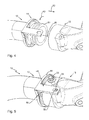
- Fig. 4 shows the second end pipe section 13 and the first end pipe section 12 with retaining element 14 arranged thereon. From a comparison of FIG Fig. 4 With Fig. 3 it can be seen that the holding element 14 has been rotated about the longitudinal axis 28 of the first pipe end portion 12. The holding element 14 was rotated in the direction of arrow 49. As a result, the projections 22, 24, 26 are engaged behind by the projections 38, 40, 42. In other words, the possibility of movement of the retaining element 14 in the direction of the pipe end 50 of the first pipe end portion is formed by the bayonet closure, which is formed by the said projections 22, 24, 26, 38, 40, 42 12 limited. The bayonet closure thus prevents movement of the holding element 14 in the direction of an arrow 52. The bayonet closure can furthermore be designed such that it also prevents a movement in the direction of the arrow 52.
- Fig. 5 shows the connecting device 10, wherein the second pipe end portion 13 is partially pushed onto the first pipe end portion 12. The pushing was done against the direction of the arrow 52 (see Fig. 4 ).
- the tab 46 has a through-hole 54.
- the passage recess 54 is formed in the end region of the tab 46 facing away from the attachment section 44.
- the through-hole 54 is aligned with a recess 56 of the second pipe end portion 13.
- a screw 58 may be partially passed through the through-hole 54 and partially screwed into the recess 56, ie, screwed to fix the first pipe end 12 at the second pipe end portion 13.
- the through-hole 54 is designed in the form of a slot in order to play the first pipe end portion 12 along its longitudinal axis 28 (see Fig. 4 ) relative to the second pipe end portion 13.
- the through-hole 54 is formed such that the second pipe end portion 13 can move toward the first pipe end portion 12, but can not move away from the first pipe end portion 12.
- the tab 46 has a guide portion 60 for abutment with the second pipe end portion 13.
- the guide portion 60 is substantially parallel to the longitudinal axis 28 (see Fig. 4 ) of the first tube end portion 12.
- the invention relates to a connecting device for fluidly sealed connection of two Rohrendabitese.
- the connecting device has a Garelelement which is mountable by a bayonet lock on a first Rohrendabites.
- the holding element has a tab which can be fastened by means of a screw of the connecting device to a second pipe end section.
- the Connecting device is structurally particularly simple design, creates a tight connection and can be mounted even in tight spaces.
Abstract
Die Erfindung betrifft eine Verbindungseinrichtung (10) zur fluidisch dichten Verbindung zweier Rohrendabschnitte (12, 13). Die Verbindungseinrichtung (10) weist ein Halteelement auf, das durch einen Bajonettverschluss an einem ersten Rohrendabschnitt (12) montierbar ist. Das Halteelement weist eine Lasche (46) auf, die mittels einer Schraube (58) der Verbindungseinrichtung (10) an einem zweiten Rohrendabschnitt (13) befestigbar ist. Die Verbindungseinrichtung (10) ist dadurch konstruktiv besonders einfach ausgebildet, schafft eine dichte Verbindung und kann auch bei beengten Verhältnissen auf einfache Weise montiert werden.The invention relates to a connecting device (10) for the fluidically sealed connection of two pipe end sections (12, 13). The connecting device (10) has a holding element which can be mounted by a bayonet catch on a first pipe end section (12). The retaining element has a tab (46) which can be fastened by means of a screw (58) of the connecting device (10) to a second pipe end section (13). The connecting device (10) is structurally particularly simple design, creates a tight connection and can be easily mounted even in tight spaces.
Description
Die Erfindung betrifft eine Verbindungseinrichtung für die fluidische Verbindung eines Fluidrohrabschnitts mit einem weiteren Fluidrohrabschnitt, insbesondere eines Turboladers mit einem Ladeluftrohr.The invention relates to a connecting device for the fluidic connection of a fluid pipe section with a further fluid pipe section, in particular a turbocharger with a charge air pipe.
Aus dem Stand der Technik ist es bekannt, einen Turbolader über ein Ladeluftrohr fluidisch mit einer weiteren Vorrichtung, beispielsweise einem Resonator, zu verbinden. Ein solches Ladeluftrohr wird auch als Ladeluftschlauch bezeichnet.From the prior art it is known to fluidly connect a turbocharger via a charge air pipe with another device, such as a resonator. Such a charge air pipe is also referred to as charge air hose.
Aus der
Schließlich werden am Markt Verbindungseinrichtungen in Form von "Schraublösungen" eingesetzt, die eine Lasche aufweisen, wobei die Lasche zwei Rohrendabschnitte verbindet und durch jeweils eine Schraube an einem Rohrendabschnitt befestigt ist.Finally, in the market connecting means in the form of "Schraublösungen" are used, which have a tab, wherein the tab connects two Rohrendabschnitte and is secured by a respective screw to a pipe end.
Die bekannten Verbindungseinrichtungen müssen entweder aufwändig und teuer produziert werden oder sind nicht zuletzt aufgrund der beengten Einbauverhältnisse im Motorraum eines Kraftfahrzeugs nur auf umständliche Art und Weise montierbar. Die Kosten zur Herstellung einer solchen Verbindungseinrichtung sind dabei vor allem deshalb kritisch, weil es sich bei den in Rede stehenden Verbindungseinrichtungen um Massenprodukte handelt.The known connecting devices must either be produced consuming and expensive or are not only due to the cramped installation conditions in the engine compartment of a motor vehicle mounted in a complicated way. The cost of producing such a connection device are critical, above all, because the connection devices in question are mass products.
Der Erfindung liegt die Aufgabe zugrunde, eine Verbindungseinrichtung für die fluidische Verbindung eines Fluidrohrabschnitts mit einem weiteren Fluidrohrabschnitt, insbesondere eines Turboladers mit einem Ladeluftrohr, bereitzustellen, die sowohl kostengünstig produzierbar als auch einfach und bequem montierbar ist.The invention has for its object to provide a connecting device for the fluidic connection of a fluid pipe section with another fluid pipe section, in particular a turbocharger with a charge air pipe, which is both inexpensive to produce and easy and convenient to install.
Diese Aufgabe wird durch eine Verbindungseinrichtung mit den Merkmalen des Anspruchs 1 gelöst. Die Unteransprüche geben zweckmäßige Weiterbildungen an.This object is achieved by a connecting device with the features of claim 1. The dependent claims indicate expedient developments.
Die erfindungsgemäße Verbindungseinrichtung für die fluidische Verbindung eines Fluidrohrabschnitts mit einem weiteren Fluidrohrabschnitt, insbesondere für die Verbindung eines Turboladers mit einem Ladeluftrohr, umfasst einen ersten Rohrendabschnitt und einen zweiten Rohrendabschnitt, wobei an dem ersten Rohrendabschnitt ein Halteelement der Verbindungseinrichtung angeordnet ist, das zumindest begrenzt um die Längsachse des ersten Rohrendabschnitts drehbar ist, wobei das Halteelement und der erste Rohrendabschnitt mehrere Vorsprünge aufweisen, die einen Bajonettverschluss zwischen dem ersten Rohrendabschnitt und dem Halteelement bilden, wobei das Halteelement eine Lasche mit einer Durchgangsausnehmung aufweist, in der eine Schraube des Halteelements geführt ist und wobei das zweite Rohrelement eine Ausnehmung aufweist, in die die Schraube eindrehbar ist.The connecting device according to the invention for the fluidic connection of a fluid pipe section with a further fluid pipe section, in particular for the connection of a turbocharger with a charge air pipe, comprises a first Rohrendabschnitt and a second Rohrendabschnitt, wherein at the first Rohrendabschnitt a holding element of the connecting device is arranged, which at least limited to the The longitudinal axis of the first pipe end portion is rotatable, wherein the holding member and the first pipe end portion having a plurality of projections which form a bayonet between the first pipe end portion and the holding member, wherein the holding member has a tab with a through-hole in which a screw of the holding member is guided the second tubular element has a recess into which the screw can be screwed.
Die Verbindungseinrichtung weist somit zwei miteinander verbindbare Rohrendabschnitte auf. Ein erster Rohrendabschnitt weist ein Halteelement auf, das zumindest begrenzt um die Längsachse des ersten Rohrendabschnitts drehbar ist. Das Halteelement weist eine Lasche auf, die mit einer Durchgangsausnehmung versehen ist. In der Durchgangsausnehmung ist eine Schraube geführt. Die Schraube erstreckt sich mithin durch die Durchgangsausnehmung der Lasche des Halteelements hindurch und ist in eine Ausnehmung des zweiten Rohrendabschnitts eindrehbar, d.h. einschraubbar. Die Ausnehmung des zweiten Rohrendabschnitts kann dazu mit einem Innengewinde versehen sein, das zu einem Außengewinde der Schraube korrespondiert. Zwischen dem Halteelement und dem ersten Rohrendabschnitt ist mittels mehrerer Vorsprünge ein Bajonettverschluss ausgebildet. Der Bajonettverschluss begrenzt zumindest die Bewegungsmöglichkeit des Halteelements in Richtung des Rohrendes des ersten Rohrendabschnitts in verbundenem Zustand der Verbindungseinrichtung. Die Verbindung der beiden Rohrendabschnitte erfolgt somit von dem ersten Rohrendabschnitt über den Bajonettverschluss zum Halteelement mit der Lasche und weiter zur Schraube, die in den zweiten Rohrendabschnitt eingedreht wird.The connecting device thus has two mutually connectable Rohrendabschnitte. A first pipe end section has a holding element which is rotatable at least limitedly about the longitudinal axis of the first pipe end section. The holding element has a tab which is provided with a through-hole. In the Durchgangsausnehmung a screw is guided. The screw thus extends through the passage recess of the tab of the retaining element and can be screwed into a recess of the second pipe end section, ie screwed. The recess of the second Rohrendabschnitts can be provided with an internal thread, which corresponds to an external thread of the screw. Between the retaining element and the first pipe end portion a bayonet closure is formed by means of a plurality of projections. The bayonet closure limits at least the possibility of movement of the retaining element in the direction of the pipe end of the first pipe end portion in the connected state of the connecting device. The connection of Both Rohrendabschnitte thus takes place from the first Rohrendabschnitt on the bayonet lock to the retaining element with the tab and on to the screw which is screwed into the second Rohrendabschnitt.
Die Verbindungseinrichtung weist einen einfachen konstruktiven Aufbau auf und ist dadurch kostengünstig produzierbar. Weiterhin ist sie in einem beengten Motorraum auf einfache Weise montierbar. Das Halteelement muss lediglich auf den ersten Rohrendabschnitt aufgesteckt und nachfolgend relativ zum ersten Rohrendabschnitt um dessen Längsachse verdreht werden, um so den Bajonettverschluss in seine Verriegelungsstellung zu überführen und dadurch das Halteelement zugfest mit dem ersten Rohrendabschnitt zu verkoppeln. Zum Schließen des Bajonettverschlusses muss daher nicht der gesamte Rohrendabschnitt gedreht werden. Die endgültige Befestigung der Verbindungseinrichtung erfolgt durch das Einschrauben der einzelnen Schraube in die Ausnehmung des zweiten Rohrendabschnitts. Dadurch sind die beiden Rohrendabschnitte zugfest und drehfest miteinander verbunden. Gegenüber bekannten "Schraublösungen" wird somit eine Schraube eingespart und die Montage insgesamt vereinfacht.The connecting device has a simple structural design and is therefore inexpensive to produce. Furthermore, it can be easily mounted in a cramped engine compartment. The retaining element only has to be plugged onto the first pipe end section and subsequently rotated relative to the first pipe end section about its longitudinal axis in order thus to transfer the bayonet closure into its locking position and thereby to connect the retaining element to the first pipe end section in a tensile-resistant manner. Therefore, to close the bayonet closure, the entire tube end section does not have to be turned. The final fastening of the connecting device takes place by screwing the single screw into the recess of the second pipe end section. As a result, the two pipe end sections are tensile and rotatably connected. Compared with known "Schraublösungen" thus a screw is saved and simplifies the installation as a whole.
Die Verbindung ist besonders stabil ausgebildet, wenn die Vorsprünge des Halteelements, die einen Teil des Bajonettverschlusses darstellen, einteilig, d.h. einstückig, mit den weiteren Bestandteilen des Halteelements ausgebildet sind. Alternativ oder zusätzlich dazu sind zur stabilen Ausbildung der Verbindung die Vorsprünge des ersten Rohrendabschnitts bevorzugt einteilig mit den weiteren Bestandteilen des Rohrendabschnitts ausgebildet.The connection is particularly stable when the projections of the retaining element, which form part of the bayonet closure, are integrally formed, i. in one piece, are formed with the other components of the retaining element. Alternatively or additionally, for the stable formation of the connection, the projections of the first pipe end section are preferably formed integrally with the further components of the pipe end section.
Die Rohrendabschnitte sind vorzugsweise ineinander einschiebbar. Beispielsweise kann der erste Rohrendabschnitt in den zweiten Rohrendabschnitt einführbar sein. Alternativ dazu kann der zweite Rohrendabschnitt in den ersten Rohrendabschnitt einführbar sein. Hierdurch kann eine fluidisch besonders dichte Verbindung erzielt werden.The Rohrendabschnitte are preferably inserted into one another. For example, the first pipe end section can be inserted into the second pipe end section. Alternatively, the second pipe end section can be inserted into the first pipe end section. As a result, a particularly fluidly sealed connection can be achieved.
Um die Handhabung der Verbindungseinrichtung für einen Monteur nochmals weiter zu vereinfachen, kann der erste Rohrendabschnitt zumindest einen Anschlag aufweisen, der die Drehung des Halteelements um den ersten Rohrendabschnitt begrenzt. Hierdurch muss der Monteur das Halteelement lediglich "bis zum Anschlag" drehen, um den korrekten Verschluss des Bajonettverschlusses sicherzustellen.In order to further simplify the handling of the connecting device for a fitter, the first pipe end section may have at least one stop, which limits the rotation of the retaining element about the first pipe end section. As a result, the fitter only has to turn the holding element "all the way" to ensure the correct closure of the bayonet closure.
Die Lasche kann erfindungsgemäß einen Führungsabschnitt zum Auffinden der korrekten Montageposition der Lasche am zweiten Rohrendabschnitt aufweisen. Der Führungsabschnitt kann dabei als ein abgewinkelter Randabschnitt der Lasche ausgebildet sein, der mit einer Führungsfläche des zweiten Rohrendabschnitts zusammenwirkt.According to the invention, the tab can have a guide section for locating the correct mounting position of the tab on the second tube end section. The guide portion may be formed as an angled edge portion of the tab, which cooperates with a guide surface of the second pipe end portion.
Das Halteelement kann einen Befestigungsabschnitt zur Lagerung des Halteelements an dem ersten Rohrendabschnitt aufweisen, der mehr als die Hälfte des Umfangs des ersten Rohrendabschnitts umfasst. Das Halteelement kann dadurch in Form einer auf den ersten Rohrendabschnitt aufpressbaren Klammer ausgebildet sein.The retaining element may have a fastening section for mounting the retaining element on the first pipe end section, which comprises more than half of the circumference of the first pipe end section. The retaining element can thereby be designed in the form of a clamp which can be pressed onto the first pipe end section.
Um eine besonders feste Verbindung zu erzielen, ist der Befestigungsabschnitt vorzugsweise im Wesentlichen ringförmig ausgebildet, wobei der Befestigungsabschnitt den Umfang des ersten Rohrendabschnitts vollständig umfasst.In order to achieve a particularly strong connection, the attachment portion is preferably substantially annular, wherein the attachment portion completely surrounds the circumference of the first tube end portion.
Die Lasche stellt ein besonders stark beanspruchtes Teil der erfindungsgemäßen Verbindungseinrichtung dar. Eine gleichzeitig feste und kostengünstige Ausbildung der Verbindungseinrichtung wird dadurch ermöglicht, dass die Lasche aus Blech ausgebildet ist.The tab is a particularly heavily loaded part of the connecting device according to the invention. A simultaneously solid and cost-effective design of the connecting device is made possible in that the tab is formed from sheet metal.
Die Stabilität der Verbindungseinrichtung ist besonders hoch, wenn die Lasche einteilig mit dem Befestigungsabschnitt ausgebildet ist. Das Halteelement kann insbesondere aus Metall oder aus einem Faserverbundwerkstoff bestehen.The stability of the connecting device is particularly high when the tab is formed integrally with the mounting portion. The holding element may in particular consist of metal or of a fiber composite material.
Zwischen dem ersten Rohrendabschnitt und dem zweiten Rohrendabschnitt kann ein elastisches Dichtungselement angeordnet oder ausgebildet sein, um eine besonders luftdichte Verbindung der Rohrendabschnitte zu erzielen. Das elastische Dichtungselement kann insbesondere ein Radialdichtungselement sein.Between the first pipe end portion and the second pipe end portion, an elastic sealing member may be arranged or formed to achieve a particularly airtight connection of the Rohrendabschnitte. The elastic sealing element may in particular be a radial sealing element.
Das elastische Dichtungselement kann einteilig mit einem Teil der Verbindungseinrichtung ausgebildet sein. Das Dichtungselement kann demgegenüber auch in Form eines Dichtringes ausgebildet sein, so dass ein kostengünstig erwerbbares, standardisiertes Dichtungselement eingesetzt wird.The elastic sealing element may be formed integrally with a part of the connecting device. In contrast, the sealing element can also be designed in the form of a sealing ring, so that a standardized, cost-effective sealing element can be used.
In einer Ausführung der erfindungsgemäßen Verbindungseinrichtung für die fluidische Verbindung eines Turboladers mit einem Ladeluftrohr kann der erste Rohrendabschnitt ein Rohrendabschnitt des Turboladers und der zweite Rohrendabschnitt ein Rohrendabschnitt des Ladeluftrohrs sein. Der erste Rohrendabschnitt kann dabei einteilig mit einem Turboladergehäuse ausgebildet sein.In one embodiment of the connecting device according to the invention for the fluidic connection of a turbocharger with a charge air pipe, the first pipe end section may be a pipe end section of the turbocharger and the second pipe end section may be a pipe end section of the charge air pipe. The first pipe end section can be formed integrally with a turbocharger housing.
Alternativ dazu kann in der Ausführung der erfindungsgemäßen Verbindungseinrichtung für die fluidische Verbindung eines Turboladers mit einem Ladeluftrohr der erste Rohrendabschnitt ein Rohrendabschnitt des Ladeluftrohrs und der zweite Rohrendabschnitt ein Rohrendabschnitt des Turboladers sein. Der zweite Rohrendabschnitt kann dabei einteilig mit einem Turboladergehäuse ausgebildet sein.Alternatively, in the embodiment of the connecting device according to the invention for the fluidic connection of a turbocharger with a charge air pipe, the first pipe end section may be a pipe end section of the charge air pipe and the second pipe end section may be a pipe end section of the turbocharger. The second pipe end portion may be formed integrally with a turbocharger housing.
Die erfindungsgemäße Verbindungseinrichtung kann zur Verbindung von Rohren zur Leitung von Luft eingesetzt werden. Die Verbindungseinrichtung kann weiterhin zur Verbindung von Rohren zur Leitung anderer Medien ausgebildet sein.The connecting device according to the invention can be used for connecting pipes for conducting air. The connecting device can furthermore be designed to connect pipes for conducting other media.
Weitere Merkmale und Vorteile der Erfindung ergeben sich aus der nachfolgenden detaillierten Beschreibung eines Ausführungsbeispiels der Erfindung, anhand der Figuren, der Zeichnung, die erfindungswesentliche Einzelheiten zeigt sowie aus den Ansprüchen.Further features and advantages of the invention will become apparent from the following detailed description of an embodiment of the invention, based on the figures, the drawing, the invention essential details shows and from the claims.
Die in der Zeichnung gezeigten Merkmale sind derart dargestellt, dass die erfindungsgemäßen Besonderheiten deutlich sichtbar gemacht werden können. Die verschiedenen Merkmale können je einzeln für sich oder zu mehreren in beliebigen Kombinationen bei Varianten der Erfindung verwirklicht sein.The features shown in the drawing are shown such that the features of the invention can be made clearly visible. The various features may be implemented individually for themselves or for a plurality of combinations in variants of the invention.
Die Zeichnung stellt die Montage einer erfindungsgemäßen Verbindungseinrichtung in Einzelschritten (
- Fig. 1
- eine perspektivische Ansicht einer Verbindungseinrichtung in verbundenem Zustand;
- Fig. 2
- eine perspektivische Ansicht eines ersten Rohrendabschnitts der Verbindungseinrichtung beim Überstreifen eines Halteelements;
- Fig. 3
- eine perspektivische Ansicht des ersten Rohrendabschnittes mit aufgezogenem Halteelement;
- Fig. 4
- eine perspektivische Ansicht der Verbindungseinrichtung beim Aufschieben eines zweiten Rohrendabschnitts auf den ersten Rohrendabschnitt; und
- Fig. 5
- eine perspektivische Ansicht der Verbindungseinrichtung beim Montieren einer Schraube zur Befestigung einer Lasche der Verbindungseinrichtung an dem zweiten Rohrendabschnitt.
- Fig. 1
- a perspective view of a connecting device in the connected state;
- Fig. 2
- a perspective view of a first pipe end portion of the connecting means when gluing a holding element;
- Fig. 3
- a perspective view of the first Rohrendabschnittes with retracted holding element;
- Fig. 4
- a perspective view of the connecting device when pushing a second pipe end portion on the first pipe end portion; and
- Fig. 5
- a perspective view of the connecting device when mounting a screw for attaching a tab of the connecting device to the second Rohrendabschnitt.
Beim Aufschieben des Halteelements 14 sind die Vorsprünge 22, 24, 26 des ersten Rohrendabschnitts 12 durch passende Ausnehmungen 32, 34, 36 führbar. Genauer gesagt ist der Vorsprung 22 durch die Ausnehmung 32, der Vorsprung 24 durch die Ausnehmung 34 und der Vorsprung 26 durch die Ausnehmung 36 führbar bzw. hindurchschiebbar.When sliding the retaining
Das Halteelement 14 weist drei Vorsprünge 38, 40, 42 auf, die in verbundenem Zustand der Verbindungseinrichtung 10 (siehe
Um eine besonders dichte Verbindung auszubilden, weist der erste Rohrendabschnitt 12 ein elastisches Dichtungselement 48 auf, das aus Gründen der Übersichtlichkeit in den folgenden Figuren nicht dargestellt ist.In order to form a particularly tight connection, the first
Die Durchgangsausnehmung 54 ist in Form eines Langlochs ausgebildet, um ein Spiel des ersten Rohrendabschnitts 12 entlang dessen Längsachse 28 (siehe
Die Lasche 46 weist einen Führungsabschnitt 60 zur Anlage an dem zweiten Rohrendabschnitt 13 auf. Der Führungsabschnitt 60 verläuft im Wesentlichen parallel zu der Längsachse 28 (siehe
Zusammenfassend betrifft die Erfindung eine Verbindungseinrichtung zur fluidisch dichten Verbindung zweier Rohrendabschnitte. Die Verbindungseinrichtung weist ein Halteelelement auf, das durch einen Bajonettverschluss an einem ersten Rohrendabschnitt montierbar ist. Das Halteelement weist eine Lasche auf, die mittels einer Schraube der Verbindungseinrichtung an einem zweiten Rohrendabschnitt befestigbar ist. Die Verbindungseinrichtung ist dadurch konstruktiv besonders einfach ausgebildet, schafft eine dichte Verbindung und kann auch bei beengten Verhältnissen montiert werden.In summary, the invention relates to a connecting device for fluidly sealed connection of two Rohrendabschnitte. The connecting device has a Halteelelement which is mountable by a bayonet lock on a first Rohrendabschnitt. The holding element has a tab which can be fastened by means of a screw of the connecting device to a second pipe end section. The Connecting device is structurally particularly simple design, creates a tight connection and can be mounted even in tight spaces.
Claims (11)
einen ersten Rohrendabschnitt (12) und einen zweiten Rohrendabschnitt (13), wobei an dem ersten Rohrendabschnitt (12) ein Halteelement (14) der Verbindungseinrichtung (10) angeordnet ist, das zumindest begrenzt um die Längsachse (28) des ersten Rohrendabschnitts (12) drehbar ist,
wobei das Halteelement (14) und der erste Rohrendabschnitt (12) mehrere Vorsprünge (22, 24, 26, 38, 40, 42) aufweisen, die einen Bajonettverschluss zwischen dem ersten Rohrendabschnitt (12) und dem Halteelement (14) bilden,
wobei das Halteelement (14) eine Lasche (46) mit einer Durchgangsausnehmung (54) aufweist, in der eine Schraube (58) des Halteelements (14) geführt ist und wobei das zweite Rohrelement (13) eine Ausnehmung (56) aufweist, in die die Schraube (58) eindrehbar ist.Connection device (10) for the fluidic connection of a fluid pipe section (16) with a further fluid pipe section (18)
a first pipe end section (12) and a second pipe end section (13), wherein at the first pipe end section (12) a holding element (14) of the connecting device (10) is arranged, which is at least limited around the longitudinal axis (28) of the first pipe end section (12). is rotatable,
the retaining element (14) and the first pipe end section (12) having a plurality of projections (22, 24, 26, 38, 40, 42) forming a bayonet joint between the first pipe end section (12) and the retaining element (14),
wherein the holding element (14) has a lug (46) with a passage recess (54) in which a screw (58) of the holding element (14) is guided and wherein the second tube element (13) has a recess (56) into which the screw (58) can be screwed in.
Applications Claiming Priority (1)
| Application Number | Priority Date | Filing Date | Title |
|---|---|---|---|
| DE102014002240.4A DE102014002240B3 (en) | 2014-02-20 | 2014-02-20 | Connecting device for the fluidic connection of a turbocharger with a charge air pipe |
Publications (1)
| Publication Number | Publication Date |
|---|---|
| EP2910792A1 true EP2910792A1 (en) | 2015-08-26 |
Family
ID=51618614
Family Applications (1)
| Application Number | Title | Priority Date | Filing Date |
|---|---|---|---|
| EP15153459.1A Withdrawn EP2910792A1 (en) | 2014-02-20 | 2015-02-02 | Connecting device for the fluid connection of a fluid tube section with another fluid tube section |
Country Status (4)
| Country | Link |
|---|---|
| US (1) | US20150233507A1 (en) |
| EP (1) | EP2910792A1 (en) |
| CN (1) | CN104864205A (en) |
| DE (1) | DE102014002240B3 (en) |
Families Citing this family (2)
| Publication number | Priority date | Publication date | Assignee | Title |
|---|---|---|---|---|
| US10543555B2 (en) * | 2016-08-16 | 2020-01-28 | Lincoln Global, Inc. | Torch clamp |
| DE102016225506A1 (en) * | 2016-12-19 | 2018-06-21 | Bayerische Motoren Werke Aktiengesellschaft | Retaining element and charge air tube system for a motor vehicle |
Citations (5)
| Publication number | Priority date | Publication date | Assignee | Title |
|---|---|---|---|---|
| BE390443A (en) * | ||||
| DE8910784U1 (en) * | 1989-09-09 | 1989-12-07 | Firma Walter Reinger, 7896 Wutoeschingen, De | |
| DE102004056600A1 (en) * | 2004-11-24 | 2006-06-01 | Volkswagen Ag | Fluid carrying pipes or container connecting arrangement for internal combustion engine, has plug with lug movable by swiveling pipe in free installation space between outer contour of another pipe/fluid container and resting projection |
| US20070216161A1 (en) | 2006-03-17 | 2007-09-20 | Mann & Hummel Gmbh | Connector for a tubular air conducting element on a turbocharger |
| US20120298063A1 (en) | 2009-12-11 | 2012-11-29 | Andreas Schieszl | Coupling device and fresh air system |
Family Cites Families (4)
| Publication number | Priority date | Publication date | Assignee | Title |
|---|---|---|---|---|
| US4858960A (en) * | 1988-11-10 | 1989-08-22 | Michael Pharaon | Hose coupling lock |
| JP2008002326A (en) * | 2006-06-21 | 2008-01-10 | Works Bell:Kk | Joint hose disconnection preventive tool |
| DE102011101506B4 (en) * | 2010-05-17 | 2015-06-18 | GM Global Technology Operations LLC (n. d. Ges. d. Staates Delaware) | Motor assembly and method of manufacture |
| ITTO20110668A1 (en) * | 2011-07-25 | 2013-01-26 | Elbi Int Spa | SYSTEM FOR REALIZING A QUICK CONNECTION OF A TUBE WITH A RECEIVING BODY, PARTICULARLY FOR USE IN MURAL AND SIMILAR BOILERS |
-
2014
- 2014-02-20 DE DE102014002240.4A patent/DE102014002240B3/en active Active
-
2015
- 2015-02-02 EP EP15153459.1A patent/EP2910792A1/en not_active Withdrawn
- 2015-02-17 CN CN201510085097.5A patent/CN104864205A/en active Pending
- 2015-02-17 US US14/623,801 patent/US20150233507A1/en not_active Abandoned
Patent Citations (5)
| Publication number | Priority date | Publication date | Assignee | Title |
|---|---|---|---|---|
| BE390443A (en) * | ||||
| DE8910784U1 (en) * | 1989-09-09 | 1989-12-07 | Firma Walter Reinger, 7896 Wutoeschingen, De | |
| DE102004056600A1 (en) * | 2004-11-24 | 2006-06-01 | Volkswagen Ag | Fluid carrying pipes or container connecting arrangement for internal combustion engine, has plug with lug movable by swiveling pipe in free installation space between outer contour of another pipe/fluid container and resting projection |
| US20070216161A1 (en) | 2006-03-17 | 2007-09-20 | Mann & Hummel Gmbh | Connector for a tubular air conducting element on a turbocharger |
| US20120298063A1 (en) | 2009-12-11 | 2012-11-29 | Andreas Schieszl | Coupling device and fresh air system |
Also Published As
| Publication number | Publication date |
|---|---|
| US20150233507A1 (en) | 2015-08-20 |
| CN104864205A (en) | 2015-08-26 |
| DE102014002240B3 (en) | 2014-10-16 |
Similar Documents
| Publication | Publication Date | Title |
|---|---|---|
| EP3009694B1 (en) | Fastening element and assembly of fastening element and holding element | |
| EP2957809B1 (en) | Coupling element for flexible connection of two elements for conducting media | |
| DE202006004407U1 (en) | Connection for a tubular air guide element on a turbocharger | |
| EP3379129B1 (en) | Connector | |
| DE102014113123A1 (en) | Coupling piece and clamp for a coupling piece | |
| DE102014103535A1 (en) | Device for fastening a component to a carrier component | |
| WO2019096596A1 (en) | Fluid conduit coupling having securing clamp | |
| EP2522894B1 (en) | Bayonet lock | |
| DE202007012400U1 (en) | Connecting device for media lines in the region of a wall duct and wall element | |
| DE102015222005A1 (en) | Conveyor | |
| DE102018108830A1 (en) | System of an attachment and a holding element | |
| DE102009036463B4 (en) | Vehicle air conditioning system and method for coupling a tubular element of a vehicle air conditioning system | |
| EP2133615B2 (en) | Fresh air assembly and coupling device | |
| DE102014002240B3 (en) | Connecting device for the fluidic connection of a turbocharger with a charge air pipe | |
| DE102016223355A1 (en) | connecting device | |
| DE102016221128A1 (en) | mounting assembly | |
| DE102009048481A1 (en) | Electrical connector | |
| DE102009021512A1 (en) | Air filter i.e. drum air filter, for internal combustion engine of e.g. motor vehicle, has filter element forming part of housing wall, where housing elements are made of flexible material i.e. silicone-like natural rubber | |
| DE202015103634U1 (en) | Pull-push rod with connecting bolt | |
| DE102007014003B4 (en) | Pipe connecting device | |
| DE102013020183A1 (en) | Holding arrangement of a conduit member to a holding part of a vehicle | |
| DE102011002186A1 (en) | Pipeline holding device for use in complex pipeline systems for holding pipelines, comprises primary holding element for holding a pipeline, and secondary holding element for holding another pipeline | |
| DE102009047957A1 (en) | Device for connecting components of fuel cell system utilized for driving vehicle, has fastening device movable in axial direction opposite to holding device such that fastening device and holding device are connected with each other | |
| EP3361134B1 (en) | Connecting unit | |
| DE102016117339A1 (en) | Device for attaching a cover to a housing |
Legal Events
| Date | Code | Title | Description |
|---|---|---|---|
| PUAI | Public reference made under article 153(3) epc to a published international application that has entered the european phase |
Free format text: ORIGINAL CODE: 0009012 |
|
| AK | Designated contracting states |
Kind code of ref document: A1 Designated state(s): AL AT BE BG CH CY CZ DE DK EE ES FI FR GB GR HR HU IE IS IT LI LT LU LV MC MK MT NL NO PL PT RO RS SE SI SK SM TR |
|
| AX | Request for extension of the european patent |
Extension state: BA ME |
|
| 17P | Request for examination filed |
Effective date: 20160219 |
|
| RBV | Designated contracting states (corrected) |
Designated state(s): AL AT BE BG CH CY CZ DE DK EE ES FI FR GB GR HR HU IE IS IT LI LT LU LV MC MK MT NL NO PL PT RO RS SE SI SK SM TR |
|
| 17Q | First examination report despatched |
Effective date: 20170116 |
|
| STAA | Information on the status of an ep patent application or granted ep patent |
Free format text: STATUS: THE APPLICATION IS DEEMED TO BE WITHDRAWN |
|
| 18D | Application deemed to be withdrawn |
Effective date: 20170527 |