EP2910390A1 - Pneumatic tire and production method therefor - Google Patents
Pneumatic tire and production method therefor Download PDFInfo
- Publication number
- EP2910390A1 EP2910390A1 EP13852743.7A EP13852743A EP2910390A1 EP 2910390 A1 EP2910390 A1 EP 2910390A1 EP 13852743 A EP13852743 A EP 13852743A EP 2910390 A1 EP2910390 A1 EP 2910390A1
- Authority
- EP
- European Patent Office
- Prior art keywords
- bead
- tire
- core
- cord
- bead cord
- Prior art date
- Legal status (The legal status is an assumption and is not a legal conclusion. Google has not performed a legal analysis and makes no representation as to the accuracy of the status listed.)
- Granted
Links
- 238000004519 manufacturing process Methods 0.000 title claims description 12
- 239000011324 bead Substances 0.000 claims abstract description 122
- 238000004804 winding Methods 0.000 claims abstract description 39
- 238000000926 separation method Methods 0.000 abstract 1
- 238000000034 method Methods 0.000 description 9
- 229920001971 elastomer Polymers 0.000 description 6
- 239000005060 rubber Substances 0.000 description 6
- 238000012360 testing method Methods 0.000 description 6
- 238000004073 vulcanization Methods 0.000 description 5
- 229920000297 Rayon Polymers 0.000 description 4
- 239000004760 aramid Substances 0.000 description 4
- 229920003235 aromatic polyamide Polymers 0.000 description 4
- 230000000694 effects Effects 0.000 description 4
- 239000002964 rayon Substances 0.000 description 4
- 238000010586 diagram Methods 0.000 description 2
- 238000010438 heat treatment Methods 0.000 description 2
- 241000254043 Melolonthinae Species 0.000 description 1
- 230000001133 acceleration Effects 0.000 description 1
- 230000015572 biosynthetic process Effects 0.000 description 1
- 238000012790 confirmation Methods 0.000 description 1
- 238000011156 evaluation Methods 0.000 description 1
- 230000002349 favourable effect Effects 0.000 description 1
- 239000000835 fiber Substances 0.000 description 1
- 239000000463 material Substances 0.000 description 1
- 238000003825 pressing Methods 0.000 description 1
- 230000003014 reinforcing effect Effects 0.000 description 1
- 238000011160 research Methods 0.000 description 1
Images





Classifications
-
- B—PERFORMING OPERATIONS; TRANSPORTING
- B60—VEHICLES IN GENERAL
- B60C—VEHICLE TYRES; TYRE INFLATION; TYRE CHANGING; CONNECTING VALVES TO INFLATABLE ELASTIC BODIES IN GENERAL; DEVICES OR ARRANGEMENTS RELATED TO TYRES
- B60C15/00—Tyre beads, e.g. ply turn-up or overlap
- B60C15/04—Bead cores
- B60C15/05—Bead cores multiple, i.e. with two or more cores in each bead
-
- B—PERFORMING OPERATIONS; TRANSPORTING
- B29—WORKING OF PLASTICS; WORKING OF SUBSTANCES IN A PLASTIC STATE IN GENERAL
- B29D—PRODUCING PARTICULAR ARTICLES FROM PLASTICS OR FROM SUBSTANCES IN A PLASTIC STATE
- B29D30/00—Producing pneumatic or solid tyres or parts thereof
- B29D30/06—Pneumatic tyres or parts thereof (e.g. produced by casting, moulding, compression moulding, injection moulding, centrifugal casting)
- B29D30/08—Building tyres
- B29D30/10—Building tyres on round cores, i.e. the shape of the core is approximately identical with the shape of the completed tyre
-
- B—PERFORMING OPERATIONS; TRANSPORTING
- B29—WORKING OF PLASTICS; WORKING OF SUBSTANCES IN A PLASTIC STATE IN GENERAL
- B29D—PRODUCING PARTICULAR ARTICLES FROM PLASTICS OR FROM SUBSTANCES IN A PLASTIC STATE
- B29D30/00—Producing pneumatic or solid tyres or parts thereof
- B29D30/06—Pneumatic tyres or parts thereof (e.g. produced by casting, moulding, compression moulding, injection moulding, centrifugal casting)
- B29D30/08—Building tyres
- B29D30/10—Building tyres on round cores, i.e. the shape of the core is approximately identical with the shape of the completed tyre
- B29D30/18—Fitting the bead-rings or bead-cores; Folding the textile layers around the rings or cores
-
- B—PERFORMING OPERATIONS; TRANSPORTING
- B29—WORKING OF PLASTICS; WORKING OF SUBSTANCES IN A PLASTIC STATE IN GENERAL
- B29D—PRODUCING PARTICULAR ARTICLES FROM PLASTICS OR FROM SUBSTANCES IN A PLASTIC STATE
- B29D30/00—Producing pneumatic or solid tyres or parts thereof
- B29D30/06—Pneumatic tyres or parts thereof (e.g. produced by casting, moulding, compression moulding, injection moulding, centrifugal casting)
- B29D30/48—Bead-rings or bead-cores; Treatment thereof prior to building the tyre
-
- B—PERFORMING OPERATIONS; TRANSPORTING
- B60—VEHICLES IN GENERAL
- B60C—VEHICLE TYRES; TYRE INFLATION; TYRE CHANGING; CONNECTING VALVES TO INFLATABLE ELASTIC BODIES IN GENERAL; DEVICES OR ARRANGEMENTS RELATED TO TYRES
- B60C15/00—Tyre beads, e.g. ply turn-up or overlap
- B60C15/0009—Tyre beads, e.g. ply turn-up or overlap features of the carcass terminal portion
- B60C15/0018—Tyre beads, e.g. ply turn-up or overlap features of the carcass terminal portion not folded around the bead core, e.g. floating or down ply
-
- B—PERFORMING OPERATIONS; TRANSPORTING
- B60—VEHICLES IN GENERAL
- B60C—VEHICLE TYRES; TYRE INFLATION; TYRE CHANGING; CONNECTING VALVES TO INFLATABLE ELASTIC BODIES IN GENERAL; DEVICES OR ARRANGEMENTS RELATED TO TYRES
- B60C15/00—Tyre beads, e.g. ply turn-up or overlap
- B60C15/04—Bead cores
-
- B—PERFORMING OPERATIONS; TRANSPORTING
- B60—VEHICLES IN GENERAL
- B60C—VEHICLE TYRES; TYRE INFLATION; TYRE CHANGING; CONNECTING VALVES TO INFLATABLE ELASTIC BODIES IN GENERAL; DEVICES OR ARRANGEMENTS RELATED TO TYRES
- B60C5/00—Inflatable pneumatic tyres or inner tubes
- B60C5/12—Inflatable pneumatic tyres or inner tubes without separate inflatable inserts, e.g. tubeless tyres with transverse section open to the rim
-
- B—PERFORMING OPERATIONS; TRANSPORTING
- B60—VEHICLES IN GENERAL
- B60C—VEHICLE TYRES; TYRE INFLATION; TYRE CHANGING; CONNECTING VALVES TO INFLATABLE ELASTIC BODIES IN GENERAL; DEVICES OR ARRANGEMENTS RELATED TO TYRES
- B60C9/00—Reinforcements or ply arrangement of pneumatic tyres
- B60C9/02—Carcasses
-
- B—PERFORMING OPERATIONS; TRANSPORTING
- B29—WORKING OF PLASTICS; WORKING OF SUBSTANCES IN A PLASTIC STATE IN GENERAL
- B29D—PRODUCING PARTICULAR ARTICLES FROM PLASTICS OR FROM SUBSTANCES IN A PLASTIC STATE
- B29D30/00—Producing pneumatic or solid tyres or parts thereof
- B29D30/06—Pneumatic tyres or parts thereof (e.g. produced by casting, moulding, compression moulding, injection moulding, centrifugal casting)
- B29D30/48—Bead-rings or bead-cores; Treatment thereof prior to building the tyre
- B29D2030/487—Forming devices for manufacturing the beads
-
- B—PERFORMING OPERATIONS; TRANSPORTING
- B60—VEHICLES IN GENERAL
- B60C—VEHICLE TYRES; TYRE INFLATION; TYRE CHANGING; CONNECTING VALVES TO INFLATABLE ELASTIC BODIES IN GENERAL; DEVICES OR ARRANGEMENTS RELATED TO TYRES
- B60C9/00—Reinforcements or ply arrangement of pneumatic tyres
- B60C9/02—Carcasses
- B60C9/04—Carcasses the reinforcing cords of each carcass ply arranged in a substantially parallel relationship
- B60C2009/0416—Physical properties or dimensions of the carcass cords
-
- B—PERFORMING OPERATIONS; TRANSPORTING
- B60—VEHICLES IN GENERAL
- B60C—VEHICLE TYRES; TYRE INFLATION; TYRE CHANGING; CONNECTING VALVES TO INFLATABLE ELASTIC BODIES IN GENERAL; DEVICES OR ARRANGEMENTS RELATED TO TYRES
- B60C15/00—Tyre beads, e.g. ply turn-up or overlap
- B60C15/04—Bead cores
- B60C2015/044—Bead cores characterised by a wrapping layer
Definitions
- the present invention relates to a pneumatic tire and a production method thereof having a bead structure where a radially inner end portion of a carcass ply is held between axially inner and outer core pieces.
- a production method by use of a rigid core (a) having an outer surface configuration being nearly identical to a tire inner surface configuration of a vulcanized tire (hereinafter called "core method") has been proposed.
- core method ti re components such as an inner liner rubber, a carcass ply, a bead core, a belt ply, a sidewall rubber and a tread rubber are sequentially applied on the rigid core (a).
- the unvulcanized tire (t) is set in a vulcanization mold (b) with the rigid core (a) and vulcanized between the rigid core (a) as an inner mold and the vulcanization mold (b) as an outer mold.
- Patent Document 1 discloses a structure shown in Fig. 11 (B) . That is to say, the bead core (d) is divided into axially inner and outer core pieces (d1, d2). And, the both end portions of the carcass ply (c) are held between the inner and outer core pieces (d1, d2).
- the inner and outer core pieces (d1, d2) are formed as a helical body formed by helically wi ndi ng a bead cord (steal cord) (e) around the tire axis.
- Patent Document 1 Japanese published unexamined application No. 2006-160236
- the present invention is grounded in limiting a final twisting direction and a winding direction of the bead cord in inner and outer core pieces and being capable of applying the tension to a carcass cord while suppressing the loosing of the carcass cord from the inner and outer core pieces so as to intend to provide a pneumatic ti re which can improve steering stability, and a manufacturing method thereof.
- a pneumatic tire comprises a carcass comprising a carcass ply extending from a tread portion through a sidewall portion to a bead core of a bead portion.
- the bead core is made of an axially inner and outer core pieces, and radially inner end portion of the carcass ply is held between the inner and outer core pieces without turning-up around the bead core.
- the inner and outer core pieces are formed of a helical body by helically winding a bead cord made of a plurality of twisted steal wires around a tire axis from radially inward to outward.
- the final twisting di recti on of the bead cord is the same as the winding direction of the bead cord around the tire axis in a side view from an axial outward of the tire.
- the final twisting direction of the bead cord is opposite to the winding direction of the bead cord around the tire axis in the side view from the axial outward of the tire.
- a production method for a pneumatic tire comprises a carcass comprising a carcass ply extending from a tread portion through a sidewall portion to a bead core of a bead portion.
- the production method comprises a green tire forming step of forming a green tire by use of a rigid core having a tire forming surface on the outer surface by sequentially applying unvulcanized tire components including the bead core and the carcass pl y on the tire forming surface.
- the green tire forming step comprises a first core piece step of forming an inner core piece on the tire forming surface by helically winding a bead cord made of a plurality of twisted steal wires around the tire axis from radially inward to outward, a carcass forming step comprising a step of applying a radially inner end portion of the carcass ply to the axially outsi de su rface of the inner core pi ece, and a second core piece step of forming the outer core piece on the axial outward of the tire of the radially inner end portion of the carcass ply by helically winding the bead cord around the tire axis from radially inward to outward.
- the final twisting di recti on of the bead cord is the same as the winding direction of the bead cord around the tire axis in the side view from the axial outward of the ti re.
- the final twisting direction of the bead cord is opposite to the winding direction of the bead cord around the tire axis in the side view from the axial outward of the tire.
- the belt layer 7 is formed of at least one belt ply, two belt plies 7A, 7B in the present embodiment, where belt cords are arranged at an angle of 10 to 35 degrees with respect to the tire circumferential direction, for example.
- the belt cords of the belt layer 7 intersect one another between plies. This increases belt rigidity and strongly reinforces the tread portion 2.
- the carcass 6 is formed of at least one carcass ply, one carcass ply 6A in the present embodiment, where an organic fiber carcass cord is arranged at an angle of 70 to 90 degrees with respect to the tire circumferential di rection, for example.
- the carcass ply 6A has a toroidal form extending between the bead portions 4, 4. And the radially inner end portion 6AE of the carcass ply 6A is not turned up around the bead core 5 but is held in the bead cores 5.
- the inner and outer core pi eces 5i, 5o are formed of a hel i cal body made by hel i cally wi ndi ng a bead cord 10 from the radially inward to the radially outward around the tire axis J.
- the present embodiment shows a case that, as shown in Fig. 1 , each of the core pieces 5i, 5o forms a line in the tire axial direction.
- the radial height of the core piece 5i, 5o can be set at a maximum, the area of contact with the carcass ply 6A can be increased, and the locking force to the both end portions 6AE of the carcass ply 6A can be improved.
- one or both of the core pi eces 5i, 5o can be also formed in two lines to improve bead rigidity.
- a z-twist cord of whi ch fi nal twi sti ng di recti on Ti is "counter clockwise rotation”, is employed as the bead cord 10i .
- This final twisting di recti on Ti is the same di recti on as the wi ndi ng di recti on Ri.
- a 5-twist cord of which final twisting direction To is "clockwise rotation”, is employed as the bead cord 10o.
- This final twi sti ng di recti on To is the opposi te di recti on to the wi ndi ng di recti on Ro.
- the bead cord 10i is, as shown in Fig. 5 , made of a pl ural i ty of steal wires F by twi sti ng together.
- the bead cord 10i has a layer twisting structure comprising a core 11 made by twisting three steal wires F together, and a sheath 12 made by twisting eight steal wires F together disposed outside thereof.
- the twisting direction of the sheath 12 (equivalent to the final twisting direction Ti) is defined as the "counterclockwise rotation" (z-twist).
- twisting structures can be employed such as a bundl e-twi sti ng structure (1 ⁇ n) made by twisting n number of steal wires F, a slash-twisting structure (m/n) made by twisting to have the same twisting direction and the same twisting pitch, and a multi-twisting structure (mxn) made by twisting m number of strands (each strand obtained by first twisting n number of steal wires F), for example.
- a bundl e-twi sti ng structure (1 ⁇ n) made by twisting n number of steal wires F
- m/n slash-twisting structure
- mxn multi-twisting structure
- the steering stability is more effectively improved when the heat shrinkage of the carcass cord 6c at 180 degrees is preferably not less than 1.5%, more preferably not less than 2.0%.
- the above-mentioned "heat shrinkage” means a dry-heat shrinkage after heating of the cord for five minutes at 180 degrees c under no-load.
- This production method comprises a green tire forming step and a vulcanizing step (shown in Fig. 11 (A) ).
- a green tire forming step by use of a rigid core (a) provided with a tire forming surface (as) on an outer surface (shown in Fig. 4 ), unvulcanized ti re components are serially applied on the tire forming surface (as). Thus a green tire (t) is formed.
- the green tire (t) is set in a vulcanization mold (b) with the rigid core (a) and vulcanized and formed.
- the green tire forming step as shown in Figs. 10 (A) - (C) , comprises a first core piece step S1, a carcass forming step S2, and a second core pi ece step S3.
- the bead cord 10i rubberized with an unvulcanized tire is helically winding from radially inward to outward around the tire axis on the tire forming surface (as) so as to form the inner core piece 5i.
- the sign 16 means an inner liner rubber.
- the carcass forming step S2 comprises a step S2a of applying the radially inner end portion 6AE of the carcass pl y 6A to the axially outside surface of the inner core piece 5i.
- the bead cord shown in Table 1 has the same specifications such as a twi sti ng structure (2/7 ⁇ 0.37), diameter of cord of 1.41 mm, and twisting pi tch of 50 mm, except the twi sti ng direction,
- cords are PET of 1670/2 dtex, rayon of 1840/2 dtex, aramid of 1100/2 dtex.
Landscapes
- Engineering & Computer Science (AREA)
- Mechanical Engineering (AREA)
- Tires In General (AREA)
- Tyre Moulding (AREA)
Abstract
Description
- The present invention relates to a pneumatic tire and a production method thereof having a bead structure where a radially inner end portion of a carcass ply is held between axially inner and outer core pieces.
- In recent years, as shown in
Fig. 11 (A) , a production method by use of a rigid core (a) having an outer surface configuration being nearly identical to a tire inner surface configuration of a vulcanized tire (hereinafter called "core method") has been proposed. In this core method, ti re components such as an inner liner rubber, a carcass ply, a bead core, a belt ply, a sidewall rubber and a tread rubber are sequentially applied on the rigid core (a). This forms an unvulcanized tire (t). The unvulcanized tire (t) is set in a vulcanization mold (b) with the rigid core (a) and vulcanized between the rigid core (a) as an inner mold and the vulcanization mold (b) as an outer mold. - In this core method, it is difficult to employing a structure that both end portions of the carcass ply are turned up around each bead core as a conventional tire. Therefore, the following
Patent Document 1 discloses a structure shown inFig. 11 (B) . That is to say, the bead core (d) is divided into axially inner and outer core pieces (d1, d2). And, the both end portions of the carcass ply (c) are held between the inner and outer core pieces (d1, d2). The inner and outer core pieces (d1, d2) are formed as a helical body formed by helically wi ndi ng a bead cord (steal cord) (e) around the tire axis. - However, i n case where the ti re was formed in the core method, a su rvey found that the tension of the carcass cord was not enough, and this possibly reduced steering stability. On the ground of this, during vulcanization, binding force of the bead core (d) to the carcass ply (c) became insufficient, the carcass ply (c) possibly moved from between the core pieces (d1, d2) in the loosing direction (radially outwardly). As a result, even if the heat shrinkage occurs in the carcass cords during the vulcanization, the tension in the carcass cord direction is not sufficiently applied owing to the movement in the loosing direction.
- And the results of the inventor's research, it was found that, the twisting di recti on T of a bead cord (e) and a wi ndi ng di recti on R around the tire axis J of the bead cord (e) caused the movement in the loosing di recti on as shown in
Fig. 12 (A) . That is, in the conventional core pi eces (d1, d2), the winding direction R of the bead cord (e) around the tire axis J was the same, and the bead cord (e) had the same twisting di recti on T. Therefore, as shown inFig. 12(B) , when the heat shrinkage (f) occurred the carcass cords (c1), in one of the inner and outer core pieces (d1, d2) (the outer core piece d2 inFig. 12 (B) ), the bead cord (e) was rotated in the untwi sti ng direction. Since the steal wi re of the cord easily moved in the untwi sti ng di recti on, the carcass pl y (c) easily moved in the heat shrinkage direction, and the tensile force did not subject. - Patent Document 1: Japanese published unexamined application No.
2006-160236 - The present invention is grounded in limiting a final twisting direction and a winding direction of the bead cord in inner and outer core pieces and being capable of applying the tension to a carcass cord while suppressing the loosing of the carcass cord from the inner and outer core pieces so as to intend to provide a pneumatic ti re which can improve steering stability, and a manufacturing method thereof.
- According to the first invention of the present application, a pneumatic tire comprises a carcass comprising a carcass ply extending from a tread portion through a sidewall portion to a bead core of a bead portion. The bead core is made of an axially inner and outer core pieces, and radially inner end portion of the carcass ply is held between the inner and outer core pieces without turning-up around the bead core. The inner and outer core pieces are formed of a helical body by helically winding a bead cord made of a plurality of twisted steal wires around a tire axis from radially inward to outward. And in the inner core pi ece, the final twisting di recti on of the bead cord is the same as the winding direction of the bead cord around the tire axis in a side view from an axial outward of the tire. In the outer core piece, the final twisting direction of the bead cord is opposite to the winding direction of the bead cord around the tire axis in the side view from the axial outward of the tire.
- According to the second invention of the present application, a production method for a pneumatic tire comprises a carcass comprising a carcass ply extending from a tread portion through a sidewall portion to a bead core of a bead portion. The production method comprises a green tire forming step of forming a green tire by use of a rigid core having a tire forming surface on the outer surface by sequentially applying unvulcanized tire components including the bead core and the carcass pl y on the tire forming surface. The green tire forming step comprises a first core piece step of forming an inner core piece on the tire forming surface by helically winding a bead cord made of a plurality of twisted steal wires around the tire axis from radially inward to outward, a carcass forming step comprising a step of applying a radially inner end portion of the carcass ply to the axially outsi de su rface of the inner core pi ece, and a second core piece step of forming the outer core piece on the axial outward of the tire of the radially inner end portion of the carcass ply by helically winding the bead cord around the tire axis from radially inward to outward. In the first core piece step, the final twisting di recti on of the bead cord is the same di recti on as the winding di recti on of the bead cord around the tire axis in the side view from the axial outward of the tire. In the second core piece step, the final twisting direction of the bead cord is opposite to the winding direction of the bead cord around the tire axis in the side view from the axial outward of the tire.
- In the inner core piece of the present invention, as disclosed above, the final twisting di recti on of the bead cord is the same as the winding direction of the bead cord around the tire axis in the side view from the axial outward of the ti re. In contrast, in the outer core pi ece, the final twisting direction of the bead cord is opposite to the winding direction of the bead cord around the tire axis in the side view from the axial outward of the tire.
- Therefore, when the heat shrinkage occurs in the carcass cord, the bead cords of the inner and outer core pieces are all twisted in the tightening direction. Thus, the binding force in the direction of the heat shrinkage increases, and it is possible to apply the tension to the carcass cord. As a result, the steering stability can be improved.
-
- [
Fig. 1 ] is a cross-sectional view showing an example of a pneumatic ti re according to the present invention. - [
Fig. 2 ] is a side view showing a core piece of a bead core. - [
Fig. 3 ] is a conceptual di agram showing a twi sti ng di recti on and a wi ndi ng direction of the bead cord in the inner and outer core pieces. - [
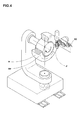
Fig. 4 ] is a diagrammatic perspective vi ew showing an example of a method of formation of the core piece. - [
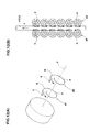
Figs. 5 ] (A) and (B) are a cross-sectional view and a diagrammatic perspective view showing the bead cord for the inner core piece in this embodiment. - [
Figs. 6 ] (A) and (B) are a cross-sectional view and a diagrammatic perspective view showing the bead cord for the outer core piece in this embodiment. - [
Fig. 7 ] is a cross-sectional view of the bead core expl ai ni ng the function effect of the present invention. - [
Fig. 8 ] is a conceptual diagram showing another example of the twisting direction and the winding direction of the bead cords in the inner and outer core pieces. - [
Figs. 9 ] (A) and (B) are brief cross-sectional views showing an example of a bead structure having a carcass made of a plurality of carcass plies. - [
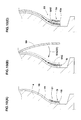
Figs. 10 ] (A) to (C) are cross-sectional views showing a fi rst core piece step, a carcass forming step, and a second core piece step. - [
Figs. 11 ] (A) is a cross-sectional view explaining a core method, and (B) is a cross-sectional view showing a bead structure to be used in the tire of the core method. - [
Figs. 12 ] (A) is a conceptual diagram showing a core piece of a conventional bead core, and (B) is a cross-sectional view showing problem points thereof. - Hereinafter, an embodiment of the present invention will be descri bed in detail.
- As shown in
Fig. 1 , apneumatic tire 1 according to the present embodiment comprises acarcass 6 extending from atread portion 2 through asidewall portion 3 to abead core 5 of abead portion 4. In the present embodiment, abelt layer 7 is disposed radially outward of thecarcass 6 and inside thetread portion 2. - The
belt layer 7 is formed of at least one belt ply, twobelt plies belt layer 7 intersect one another between plies. This increases belt rigidity and strongly reinforces thetread portion 2. - In this embodiment, radially outside of the
belt layer 7, there is provided aband layer 9 made of a band cord spirally wound with respect to the circumferential direction for improving high-speed durability and the like. For theband layer 9, a pair of edge band plies to cover only the axially outer end portion of thebelt layer 7 and a full band ply to cover substantially overall width of thebelt layer 7 can be employed. The present embodiment shows a case that theband layer 9 is formed of a single full band ply. - The
carcass 6 is formed of at least one carcass ply, onecarcass ply 6A in the present embodiment, where an organic fiber carcass cord is arranged at an angle of 70 to 90 degrees with respect to the tire circumferential di rection, for example. Thecarcass ply 6A has a toroidal form extending between thebead portions carcass ply 6A is not turned up around thebead core 5 but is held in thebead cores 5. - Specifically, the
bead core 5 is made of axially inner andouter core pieces 5i , 5o. And the radially inner end portion 6AE of thecarcass ply 6A is held between the inner andouter core pieces 5i , 5o. Thebead portion 4 is provided with inner and outerbead apex rubbers 8i, 8o extending from the inner andouter core pieces 5i , 5o toward the radially outward respectively in a tapered manner, thereby reinforcing between thebead portion 4 and thesidewall portion 3. Thesign 15 in drawings means a chafer rubber for preventing rim shifting. - As shown in
Fig. 2 , the inner and outercore pi eces 5i, 5o are formed of a hel i cal body made by hel i cally wi ndi ng abead cord 10 from the radially inward to the radially outward around the tire axis J. The present embodiment shows a case that, as shown inFig. 1 , each of thecore pieces 5i, 5o forms a line in the tire axial direction. Therefore, within a limited winding number of thebead cord 10, the radial height of thecore piece 5i, 5o can be set at a maximum, the area of contact with thecarcass ply 6A can be increased, and the locking force to the both end portions 6AE of thecarcass ply 6A can be improved. Moreover, upon request, one or both of thecore pi eces 5i, 5o can be also formed in two lines to improve bead rigidity. - And in the present invention, as schematically shown in
Fig. 3 , - (1) in the
inner core piece 5i, the final twisting direction Ti of thebead cord 10i is the same as the winding direction Ri of thebead cord 10i around the tire axis J in the side view from the axial outward of the tire, and - (2) in the outer core piece 5o, the final twisting direction To of the bead cord 10o is opposite to the winding direction Ro of the bead cord 10o around the tire axis J in the side view from the axial outward of the tire. In other words, Ti = Ri and To ≠ Ro.
- For example, as schematically shown in
Fig. 4 , each of therespective core pieces 5i, 5o is formed as a helical form by pressing thebead cord 10 against a rotating rigid core (a). Thus, in a normal case, the winding di recti on Ri of thebead cord 10i in the innercore pi ece 5i and the wi ndi ng direction Ro of the bead cord 10o in the outer core piece 5o become the same (Ri =Ro.).Figs. 2 and3 show a case that each of the wi ndi ng di recti ons Ri and Ro is "counterclockwise rotation". - Therefore, in the present embodiment, for the
inner core piece 5i, a z-twist cord, of whi ch fi nal twi sti ng di recti on Ti is "counter clockwise rotation", is employed as thebead cord 10i . This final twisting di recti on Ti is the same di recti on as the wi ndi ng di recti on Ri. For the outer core piece 5o, a 5-twist cord, of which final twisting direction To is "clockwise rotation", is employed as the bead cord 10o. This final twi sti ng di recti on To is the opposi te di recti on to the wi ndi ng di recti on Ro. In other words, Ti ≠ To. - Specifically, the
bead cord 10i is, as shown inFig. 5 , made of a pl ural i ty of steal wires F by twi sti ng together. In the present embodiment, thebead cord 10i has a layer twisting structure comprising a core 11 made by twisting three steal wires F together, and asheath 12 made by twisting eight steal wires F together disposed outside thereof. In this time, the twisting direction of the sheath 12 (equivalent to the final twisting direction Ti) is defined as the "counterclockwise rotation" (z-twist). - However, the bead cord 10o has, as shown in
Fig. 6 , the same structure as thebead cord 10i except the twisting direction. And the twisting direction of the sheath 12 (equivalent to the final twisting direction To) is defined as the "clockwise rotation" (S-twist). - For the
bead cords 10i, 10o, when the final twisting directions Ti, To are identified, various twisting structures can be employed such as a bundl e-twi sti ng structure (1×n) made by twisting n number of steal wires F, a slash-twisting structure (m/n) made by twisting to have the same twisting direction and the same twisting pitch, and a multi-twisting structure (mxn) made by twisting m number of strands (each strand obtained by first twisting n number of steal wires F), for example. - To construct as above, as shown in
Fig. 7 , when heat shrinkage (f) occurs in thecarcass cord 6c, thebead cord 10i of theinner core piece 5i and the bead cord 10o of the outer core piece 5o are twisted in a ti ghteni ng di recti on of the outermost twi sti ng of the cord, respectively. This allows the binding force to work effectively against the direction of the heat shrinkage (f), and allow to give tensile force to thecarcass cord 6c, and to improve the steering stability. Such an effect is more produced when the cord has the final twisting pitch of not more than 50 mm. - Incidentally, when the heat shrinkage of the
carcass cord 6c itself is too small, it cannot improve the steering stability even if the binding force is improved since the tensile force is not given to thecarcass cord 6c. Therefore, in the present invention, the steering stability is more effectively improved when the heat shrinkage of thecarcass cord 6c at 180 degrees is preferably not less than 1.5%, more preferably not less than 2.0%. According to "Dry-heat shrinkage after heating (Method B)" shown in section 8.10 (b) of JIS-L1017, the above-mentioned "heat shrinkage" means a dry-heat shrinkage after heating of the cord for five minutes at 180 degrees c under no-load. - Naturally, when both of the winding direction Ri of the
bead cord 10i in theinner core piece 5i and the winding direction Ro of the bead cord 10o in the outer core piece 5o are "clockwise rotation", thebead cord 10i having the final twisting direction Ti of "clockwise rotation" (s-twist) is employed for theinner core piece 5i. And the bead cord 10o having the final twisting direction To of "counterclockwise rotation" (z-twist) is employed for the outer core piece 5o. - As conceptually shown in
Fig. 8 , when the winding direction Ri of thebead cord 10i in theinner core piece 5i is the "counterclockwise rotati on" and the wi ndi ng direction Ro of the bead cord 10o of the outer core piece 5o is the "clockwise rotation", the same cords having the final twisting direction Ti, To of the "counterclockwise rotation" (z-twist) can be employed for thebead cords 10i, 10o, respectively. Meanwhile, when the wi ndi ng di recti on Ri of thebead cord 10i in the innercore pi ece 5i is the "clockwise rotation" and the winding direction Ro of the bead cord 10o in the outer core piece 5o is the "counterclockwise rotation", the same cords having the final twisting directions Ti, To of the "clockwise rotation" (s-twist) can be employed for thebead cords 10i, 10o, respectively. - Further, when the number of the
carcass ply 6A is plural, two carcass plies 6A for example, as shown inFig. 9 (A) , the plurality of carcass plies 6Acan be hel d between the inner andouter core pieces 5i , 5o. However, as shown inFig. 9 (B) , it is preferable to provide a plurality of the pai rs of inner and outercore pi eces 5i, 5o and to hold each of the carcass plies 6A between the respective inner andouter core pieces 5i, 5o so as to improve the binding force. - Next, a method of manufacturing the
pneumatic tire 1wi 11 be descri bed in detail. This production method comprises a green tire forming step and a vulcanizing step (shown inFig. 11 (A) ). In the green tire forming step, by use of a rigid core (a) provided with a tire forming surface (as) on an outer surface (shown inFig. 4 ), unvulcanized ti re components are serially applied on the tire forming surface (as). Thus a green tire (t) is formed. In the vulcanizing step, the green tire (t) is set in a vulcanization mold (b) with the rigid core (a) and vulcanized and formed. - The green tire forming step, as shown in
Figs. 10 (A) - (C) , comprises a first core piece step S1, a carcass forming step S2, and a second core pi ece step S3. In the fi rst core pi ece step S1, thebead cord 10i rubberized with an unvulcanized tire is helically winding from radially inward to outward around the tire axis on the tire forming surface (as) so as to form theinner core piece 5i. Thesign 16 means an inner liner rubber. - The carcass forming step S2 comprises a step S2a of applying the radially inner end portion 6AE of the
carcass pl y 6A to the axially outside surface of theinner core piece 5i. - In the second core piece step S3, axially outward of the radially inner end portion 6AE of the
carcass ply 6A, the rubberized bead cord 10o is helically wound around the ti re axis from radially inward to outward so as to form the outer core piece 5o. - At this time, as shown in
Figs. 3 and8 , in the first core piece step S1, the final twisting direction Ti of thebead cord 10i has the same direction as the winding direction Ri of thebead cord 10i around the tire axis J in the side view from the axial outward of the tire. In the second core piece step S3, the final twisting direction To of the bead cord 10o has an opposite direction to the winding direction Ro of the bead cord 10o around the ti re axis J in the side view from the axial outward of the tire. - The above has described in detail a particularly preferred embodiment of the present invention, the invention is not limited to the embodiment shown, can be implemented by modifying to various aspects.
- For confirmation of the effects of the present invention, a pneumatic tire (225/40R18) having an inner structure shown in
Fig. 1 was made in the core method. The bead structure of each test tire was based on the specifications shown in Table 1. Each test tire was tested in steering stability, and the test results were compared. In each tire, the bead cores on one side and the other side of the tire equator have same structures as shown in Table 1. - The bead cord shown in Table 1 has the same specifications such as a twi sti ng structure (2/7×0.37), diameter of cord of 1.41 mm, and twisting pi tch of 50 mm, except the twi sti ng direction, In respect to the carcass cord, cords are PET of 1670/2 dtex, rayon of 1840/2 dtex, aramid of 1100/2 dtex.
- Under rim (8.5J) and internal pressu re (210 kPa), the test ti res were mounted on all four wheels of a vehicle (2000cc, FR car), and test was conducted on a course in Okayama International Circuit (five laps continuous running) in braking, turning, acceleration, handling, lap time. Evaluation was performed in a professional driver's feeling test and displayed on a scale of one to ten. The larger the numeric values were, the more favorable it was in the steering stability.
[Table 1] Com. Ex. 1 Com. Ex. 2 Com. Ex. 3 Com. Ex. 4 Com. Ex. 5 Ex. 1 Ex. 2 Ex. 3 Ex. 4 Com. Ex. 6 Com. Ex. 7 Com. Ex. 8 Com. Ex. 9 Carcass cord Material PET PET PET rayon aramid PET PET rayon aramid PET PET rayon aramid Heat shrinkage 4.0 4.0 2.0 1.5 0.0 4.0 2.0 1.5 0.0 4.0 2.0 1.5 0.0 Inner core piece winding direction of cord clockwise rotation clockwise rotation clockwise rotation Final twisting direction of cord clockwise rotation counterclockwise rotation clockwise rotation clockwise rotation clockwise rotation clockwise rotation counterclockwise rotation (s-twist) (z-twist) (s-twist) (s-twist) (s-twist) (s-twist) (z-twist) Outer core piece winding direction of cord clockwise rotation clockwise rotation clockwise rotation Final twisting direction of cord clockwise rotation counterclockwise rotation clockwise rotation clockwise rotation clockwise rotation counterclockwise rotation clockwise rotation (s-twist) (z-twist) (s-twist) (s-twist) (s-twist) (z-twist) (s-twist) Steering stability 7 7 5 6 5 9 6 7 5 6.5 4.5 5.5 5 - Tire of the present embodiment as shown in the table, excellent steering stability was confirmed.
-
- 1
- Pneumatic tire
- 2
- Tread portion
- 3
- sidewall portion
- 4
- Bead portion
- 5
- Bead core
- 5i
- Inner core piece
- 5o
- Outer core piece
- 6
- Carcass
- 6A
- Carcass ply
- 6AE
- inner end portion
- 10, 10i, 10o
- Bead cord
- F
- Steal wire
- Ri, Ro
- winding direction
- S1
- First core piece step
- S2
- Carcass forming step
- S3
- Second core piece step
- Ti, To
- Twisting direction
Claims (6)
- A pneumatic tire comprising a carcass comprising a carcass ply extending from a tread portion through a sidewall portion to a bead core of a bead portion; wherein
the bead core is made of an axially inner and outer core pieces, and radially inner end portion of the carcass ply is held between the inner and outer core pieces without turning-up around the bead core;
the inner and outer core pieces are formed of a helical body by helically winding a bead cord made of a plurality of twisted steal wires around a tire axis from radially inward to outward; and
in the inner core piece, the final twisting direction of the bead cord is the same as the winding direction of the bead cord around the tire axis in a side view from an axial outward of the tire, and in the outer core pi ece, the final twisting direction of the bead cord is opposite to the winding direction of the bead cord around the tire axis in the side view from the axial outward of the tire. - The pneumatic tire as set forth in claim 1, wherein the winding direction of the bead cord around the tire axis in the inner core piece is the same as the winding direction of the bead cord around the tire axis in the outer core piece.
- The pneumatic tire as set forth in claim 1 or 2, wherein the carcass ply has a carcass cord of which heat shrinkage at 180 degrees C is not less than 1.5%.
- A production method for a pneumatic tire comprising a carcass comprising a carcass ply extending from a tread portion through a sidewall portion to a bead core of a bead portion, wherein
the production method comprises a green tire forming step of forming a green tire by use of a rigid core having a tire forming surface on the outer surface by sequentially applying unvulcanized tire components including the bead core and the carcass ply on the tire forming surface;
the green tire forming step comprisesa fi rst core pi ece step of forming an inner core pi ece on the ti re forming surface by helically winding a bead cord made of a plurality of twisted steal wi res around the tire axis from radially inward to outward,a carcass forming step comprising a step of applying a radially inner end portion of the carcass ply to the axially outside surface of the inner core piece, anda second core piece step of forming an outer core piece on the axial outward of the ti re of the radially inner end portion of the carcass ply by helically winding the bead cord around the tire axis from radially inward to outward; andin the first core piece step, the final twisting direction of the bead cord is the same di recti on as the winding di recti on of the bead cord around the tire axis in a side view from the axial outward of the ti re, and
in the second core piece step, the final twisting direction of the bead cord is opposite to the winding direction of the bead cord around the tire axis in the side view from the axial outward of the tire. - The production method for a pneumatic tire as set forth in claim 4, wherein the winding direction of the bead cord in the first core piece step is the same as the winding di recti on of the bead cord in the second core piece step.
- The production method for a pneumatic tire as set forth in claim 4 or 5, wherein the carcass ply has a carcass cord of which heat shrinkage at 180 degrees c is not less than 1.5%.
Applications Claiming Priority (2)
| Application Number | Priority Date | Filing Date | Title |
|---|---|---|---|
| JP2012247715A JP6074230B2 (en) | 2012-11-09 | 2012-11-09 | Pneumatic tire and manufacturing method thereof |
| PCT/JP2013/077132 WO2014073303A1 (en) | 2012-11-09 | 2013-10-04 | Pneumatic tire and production method therefor |
Publications (3)
| Publication Number | Publication Date |
|---|---|
| EP2910390A1 true EP2910390A1 (en) | 2015-08-26 |
| EP2910390A4 EP2910390A4 (en) | 2016-05-25 |
| EP2910390B1 EP2910390B1 (en) | 2019-01-16 |
Family
ID=50684420
Family Applications (1)
| Application Number | Title | Priority Date | Filing Date |
|---|---|---|---|
| EP13852743.7A Active EP2910390B1 (en) | 2012-11-09 | 2013-10-04 | Pneumatic tire and production method therefor |
Country Status (5)
| Country | Link |
|---|---|
| US (1) | US10189317B2 (en) |
| EP (1) | EP2910390B1 (en) |
| JP (1) | JP6074230B2 (en) |
| CN (2) | CN108274959B (en) |
| WO (1) | WO2014073303A1 (en) |
Cited By (1)
| Publication number | Priority date | Publication date | Assignee | Title |
|---|---|---|---|---|
| EP2987657A4 (en) * | 2013-05-07 | 2016-12-28 | Sumitomo Rubber Ind | PNEUMATIC |
Families Citing this family (2)
| Publication number | Priority date | Publication date | Assignee | Title |
|---|---|---|---|---|
| JP6848262B2 (en) * | 2016-08-22 | 2021-03-24 | 住友ゴム工業株式会社 | Pneumatic tires |
| KR20230080418A (en) * | 2020-10-09 | 2023-06-07 | 꽁빠니 제네날 드 에따블리세망 미쉘린 | Tires comprising a single carcass layer |
Family Cites Families (23)
| Publication number | Priority date | Publication date | Assignee | Title |
|---|---|---|---|---|
| FR2299168A2 (en) * | 1975-01-29 | 1976-08-27 | Michelin & Cie | IMPROVEMENTS TO TIRE PACKAGES |
| FR2694521A1 (en) * | 1992-08-05 | 1994-02-11 | Sedepro | Anchoring the carcass of a tire. |
| FR2736006A1 (en) * | 1995-06-29 | 1997-01-03 | Sedepro | TIRE COMPRISING CIRCUMFERENTIAL CABLES FOR ANCHORING THE CARCASS, PROCESS FOR PREPARING SUCH CABLES |
| JP3777241B2 (en) * | 1997-05-06 | 2006-05-24 | 横浜ゴム株式会社 | Pneumatic radial tire |
| JP3735447B2 (en) * | 1997-06-09 | 2006-01-18 | 横浜ゴム株式会社 | Pneumatic tire |
| JP2001097010A (en) * | 1999-09-30 | 2001-04-10 | Bridgestone Corp | Pneumatic tire |
| ATE298674T1 (en) * | 1999-12-03 | 2005-07-15 | Michelin Soc Tech | BEAD FOR FLAT TIRES |
| EP1254034B1 (en) * | 1999-12-03 | 2005-08-03 | Société de Technologie Michelin | Tyre bead with extended mobility |
| JP2002012011A (en) * | 2000-06-29 | 2002-01-15 | Bridgestone Corp | Pneumatic tire |
| CN100391753C (en) * | 2002-07-23 | 2008-06-04 | 米其林技术公司 | Tires with non-linear fixed reinforcements |
| JP4235032B2 (en) * | 2003-05-23 | 2009-03-04 | 不二精工株式会社 | Bead core and pneumatic radial tire using the same |
| FR2870164B1 (en) * | 2004-05-12 | 2006-07-14 | Michelin Soc Tech | PNEUMATIC AND COMPOSITE METAL / RUBBER FOR PNEUMATIC |
| JP2006044339A (en) * | 2004-08-02 | 2006-02-16 | Yokohama Rubber Co Ltd:The | Pneumatic radial-ply tire |
| JP4695429B2 (en) * | 2004-11-11 | 2011-06-08 | 住友ゴム工業株式会社 | Pneumatic tire and manufacturing method thereof |
| DE102005000755A1 (en) * | 2005-01-04 | 2006-07-20 | Continental Aktiengesellschaft | Vehicle tires |
| JP4312173B2 (en) * | 2005-05-24 | 2009-08-12 | 住友ゴム工業株式会社 | Pneumatic tires for motorcycles |
| BRPI0710455A2 (en) | 2006-04-19 | 2011-08-16 | Pioneer Hi Bred Int | isolated polypeptide, isolated polynucleotide and methods for increasing the level of a polypeptide in a plant, modulating the level of a polypeptide in a plant and modifying plant growth |
| JP2010115957A (en) * | 2008-11-11 | 2010-05-27 | Bridgestone Corp | Bead part structure for pneumatic tire |
| JP5227392B2 (en) * | 2010-12-16 | 2013-07-03 | 住友ゴム工業株式会社 | Pneumatic tire and method for manufacturing pneumatic tire |
| JP5302987B2 (en) * | 2011-01-31 | 2013-10-02 | 住友ゴム工業株式会社 | Pneumatic tire manufacturing method |
| JP5144783B2 (en) | 2011-04-08 | 2013-02-13 | 住友ゴム工業株式会社 | Pneumatic tire and manufacturing method thereof |
| WO2013088936A1 (en) * | 2011-12-15 | 2013-06-20 | 住友ゴム工業株式会社 | Pneumatic tyre and manufacturing method therefor |
| JP6043553B2 (en) * | 2012-09-10 | 2016-12-14 | 住友ゴム工業株式会社 | Pneumatic tire |
-
2012
- 2012-11-09 JP JP2012247715A patent/JP6074230B2/en not_active Expired - Fee Related
-
2013
- 2013-10-04 CN CN201810182710.9A patent/CN108274959B/en active Active
- 2013-10-04 CN CN201380055847.3A patent/CN104768778B/en active Active
- 2013-10-04 WO PCT/JP2013/077132 patent/WO2014073303A1/en not_active Ceased
- 2013-10-04 EP EP13852743.7A patent/EP2910390B1/en active Active
- 2013-10-04 US US14/436,758 patent/US10189317B2/en active Active
Cited By (2)
| Publication number | Priority date | Publication date | Assignee | Title |
|---|---|---|---|---|
| EP2987657A4 (en) * | 2013-05-07 | 2016-12-28 | Sumitomo Rubber Ind | PNEUMATIC |
| US10112445B2 (en) | 2013-05-07 | 2018-10-30 | Sumitomo Rubber Industries, Ltd. | Pneumatic tire |
Also Published As
| Publication number | Publication date |
|---|---|
| EP2910390A4 (en) | 2016-05-25 |
| CN108274959A (en) | 2018-07-13 |
| JP2014094684A (en) | 2014-05-22 |
| CN104768778B (en) | 2018-09-21 |
| US20150258862A1 (en) | 2015-09-17 |
| CN104768778A (en) | 2015-07-08 |
| JP6074230B2 (en) | 2017-02-01 |
| EP2910390B1 (en) | 2019-01-16 |
| CN108274959B (en) | 2020-06-09 |
| US10189317B2 (en) | 2019-01-29 |
| WO2014073303A1 (en) | 2014-05-15 |
Similar Documents
| Publication | Publication Date | Title |
|---|---|---|
| JP2757940B2 (en) | Pneumatic tire | |
| EP2065223B1 (en) | Pneumatic radial tire | |
| EP2308694B1 (en) | Pneumatic tire | |
| EP2783842B1 (en) | Method for manufacturing pneumatic tire | |
| EP2017093A2 (en) | Pneumatic tire | |
| EP2684712B1 (en) | Pneumatic tire, and method for manufacturing same | |
| EP3135465B1 (en) | Pneumatic tire, and pneumatic tire production method | |
| EP2987657B1 (en) | Pneumatic tire | |
| JP7088350B2 (en) | Cord / rubber complex and pneumatic tire | |
| EP2910390B1 (en) | Pneumatic tire and production method therefor | |
| EP3061630B1 (en) | Pneumatic tire | |
| EP3106321B1 (en) | Pneumatic tire | |
| JPH0396402A (en) | Pneumatic radial tire | |
| EP2808178B1 (en) | Tire reinforcing member and pneumatic tire using same | |
| EP3792079B1 (en) | Heavy-duty pneumatic tire | |
| US12539717B2 (en) | Pneumatic tire | |
| EP3090885B1 (en) | Pneumatic tire | |
| CN113661075B (en) | Hybrid cord and tire having the same | |
| US20110139328A1 (en) | Process for building green tyre for vehicle wheels and tyres built by said process | |
| JP6247730B2 (en) | Pneumatic tire and manufacturing method thereof | |
| EP3335906B1 (en) | Pneumatic tire | |
| JPH10305711A (en) | Pneumatic radial tire | |
| WO2024134977A1 (en) | Motorcycle tire | |
| JP2015077884A (en) | Pneumatic tire |
Legal Events
| Date | Code | Title | Description |
|---|---|---|---|
| PUAI | Public reference made under article 153(3) epc to a published international application that has entered the european phase |
Free format text: ORIGINAL CODE: 0009012 |
|
| 17P | Request for examination filed |
Effective date: 20150519 |
|
| AK | Designated contracting states |
Kind code of ref document: A1 Designated state(s): AL AT BE BG CH CY CZ DE DK EE ES FI FR GB GR HR HU IE IS IT LI LT LU LV MC MK MT NL NO PL PT RO RS SE SI SK SM TR |
|
| AX | Request for extension of the european patent |
Extension state: BA ME |
|
| DAX | Request for extension of the european patent (deleted) | ||
| RA4 | Supplementary search report drawn up and despatched (corrected) |
Effective date: 20160428 |
|
| RIC1 | Information provided on ipc code assigned before grant |
Ipc: B60C 9/00 20060101ALI20160421BHEP Ipc: B29D 30/10 20060101ALI20160421BHEP Ipc: B60C 15/04 20060101ALI20160421BHEP Ipc: B60C 15/00 20060101AFI20160421BHEP |
|
| GRAP | Despatch of communication of intention to grant a patent |
Free format text: ORIGINAL CODE: EPIDOSNIGR1 |
|
| STAA | Information on the status of an ep patent application or granted ep patent |
Free format text: STATUS: GRANT OF PATENT IS INTENDED |
|
| INTG | Intention to grant announced |
Effective date: 20180802 |
|
| GRAS | Grant fee paid |
Free format text: ORIGINAL CODE: EPIDOSNIGR3 |
|
| GRAA | (expected) grant |
Free format text: ORIGINAL CODE: 0009210 |
|
| STAA | Information on the status of an ep patent application or granted ep patent |
Free format text: STATUS: THE PATENT HAS BEEN GRANTED |
|
| AK | Designated contracting states |
Kind code of ref document: B1 Designated state(s): AL AT BE BG CH CY CZ DE DK EE ES FI FR GB GR HR HU IE IS IT LI LT LU LV MC MK MT NL NO PL PT RO RS SE SI SK SM TR |
|
| REG | Reference to a national code |
Ref country code: GB Ref legal event code: FG4D |
|
| REG | Reference to a national code |
Ref country code: CH Ref legal event code: EP |
|
| REG | Reference to a national code |
Ref country code: IE Ref legal event code: FG4D |
|
| REG | Reference to a national code |
Ref country code: DE Ref legal event code: R096 Ref document number: 602013050043 Country of ref document: DE |
|
| REG | Reference to a national code |
Ref country code: AT Ref legal event code: REF Ref document number: 1089444 Country of ref document: AT Kind code of ref document: T Effective date: 20190215 |
|
| REG | Reference to a national code |
Ref country code: NL Ref legal event code: MP Effective date: 20190116 |
|
| REG | Reference to a national code |
Ref country code: LT Ref legal event code: MG4D |
|
| PG25 | Lapsed in a contracting state [announced via postgrant information from national office to epo] |
Ref country code: NL Free format text: LAPSE BECAUSE OF FAILURE TO SUBMIT A TRANSLATION OF THE DESCRIPTION OR TO PAY THE FEE WITHIN THE PRESCRIBED TIME-LIMIT Effective date: 20190116 |
|
| REG | Reference to a national code |
Ref country code: AT Ref legal event code: MK05 Ref document number: 1089444 Country of ref document: AT Kind code of ref document: T Effective date: 20190116 |
|
| PG25 | Lapsed in a contracting state [announced via postgrant information from national office to epo] |
Ref country code: PT Free format text: LAPSE BECAUSE OF FAILURE TO SUBMIT A TRANSLATION OF THE DESCRIPTION OR TO PAY THE FEE WITHIN THE PRESCRIBED TIME-LIMIT Effective date: 20190516 Ref country code: ES Free format text: LAPSE BECAUSE OF FAILURE TO SUBMIT A TRANSLATION OF THE DESCRIPTION OR TO PAY THE FEE WITHIN THE PRESCRIBED TIME-LIMIT Effective date: 20190116 Ref country code: SE Free format text: LAPSE BECAUSE OF FAILURE TO SUBMIT A TRANSLATION OF THE DESCRIPTION OR TO PAY THE FEE WITHIN THE PRESCRIBED TIME-LIMIT Effective date: 20190116 Ref country code: NO Free format text: LAPSE BECAUSE OF FAILURE TO SUBMIT A TRANSLATION OF THE DESCRIPTION OR TO PAY THE FEE WITHIN THE PRESCRIBED TIME-LIMIT Effective date: 20190416 Ref country code: FI Free format text: LAPSE BECAUSE OF FAILURE TO SUBMIT A TRANSLATION OF THE DESCRIPTION OR TO PAY THE FEE WITHIN THE PRESCRIBED TIME-LIMIT Effective date: 20190116 Ref country code: PL Free format text: LAPSE BECAUSE OF FAILURE TO SUBMIT A TRANSLATION OF THE DESCRIPTION OR TO PAY THE FEE WITHIN THE PRESCRIBED TIME-LIMIT Effective date: 20190116 Ref country code: LT Free format text: LAPSE BECAUSE OF FAILURE TO SUBMIT A TRANSLATION OF THE DESCRIPTION OR TO PAY THE FEE WITHIN THE PRESCRIBED TIME-LIMIT Effective date: 20190116 |
|
| PG25 | Lapsed in a contracting state [announced via postgrant information from national office to epo] |
Ref country code: BG Free format text: LAPSE BECAUSE OF FAILURE TO SUBMIT A TRANSLATION OF THE DESCRIPTION OR TO PAY THE FEE WITHIN THE PRESCRIBED TIME-LIMIT Effective date: 20190416 Ref country code: GR Free format text: LAPSE BECAUSE OF FAILURE TO SUBMIT A TRANSLATION OF THE DESCRIPTION OR TO PAY THE FEE WITHIN THE PRESCRIBED TIME-LIMIT Effective date: 20190417 Ref country code: HR Free format text: LAPSE BECAUSE OF FAILURE TO SUBMIT A TRANSLATION OF THE DESCRIPTION OR TO PAY THE FEE WITHIN THE PRESCRIBED TIME-LIMIT Effective date: 20190116 Ref country code: RS Free format text: LAPSE BECAUSE OF FAILURE TO SUBMIT A TRANSLATION OF THE DESCRIPTION OR TO PAY THE FEE WITHIN THE PRESCRIBED TIME-LIMIT Effective date: 20190116 Ref country code: LV Free format text: LAPSE BECAUSE OF FAILURE TO SUBMIT A TRANSLATION OF THE DESCRIPTION OR TO PAY THE FEE WITHIN THE PRESCRIBED TIME-LIMIT Effective date: 20190116 Ref country code: IS Free format text: LAPSE BECAUSE OF FAILURE TO SUBMIT A TRANSLATION OF THE DESCRIPTION OR TO PAY THE FEE WITHIN THE PRESCRIBED TIME-LIMIT Effective date: 20190516 |
|
| REG | Reference to a national code |
Ref country code: DE Ref legal event code: R097 Ref document number: 602013050043 Country of ref document: DE |
|
| PG25 | Lapsed in a contracting state [announced via postgrant information from national office to epo] |
Ref country code: IT Free format text: LAPSE BECAUSE OF FAILURE TO SUBMIT A TRANSLATION OF THE DESCRIPTION OR TO PAY THE FEE WITHIN THE PRESCRIBED TIME-LIMIT Effective date: 20190116 Ref country code: CZ Free format text: LAPSE BECAUSE OF FAILURE TO SUBMIT A TRANSLATION OF THE DESCRIPTION OR TO PAY THE FEE WITHIN THE PRESCRIBED TIME-LIMIT Effective date: 20190116 Ref country code: SK Free format text: LAPSE BECAUSE OF FAILURE TO SUBMIT A TRANSLATION OF THE DESCRIPTION OR TO PAY THE FEE WITHIN THE PRESCRIBED TIME-LIMIT Effective date: 20190116 Ref country code: RO Free format text: LAPSE BECAUSE OF FAILURE TO SUBMIT A TRANSLATION OF THE DESCRIPTION OR TO PAY THE FEE WITHIN THE PRESCRIBED TIME-LIMIT Effective date: 20190116 Ref country code: EE Free format text: LAPSE BECAUSE OF FAILURE TO SUBMIT A TRANSLATION OF THE DESCRIPTION OR TO PAY THE FEE WITHIN THE PRESCRIBED TIME-LIMIT Effective date: 20190116 Ref country code: DK Free format text: LAPSE BECAUSE OF FAILURE TO SUBMIT A TRANSLATION OF THE DESCRIPTION OR TO PAY THE FEE WITHIN THE PRESCRIBED TIME-LIMIT Effective date: 20190116 Ref country code: AT Free format text: LAPSE BECAUSE OF FAILURE TO SUBMIT A TRANSLATION OF THE DESCRIPTION OR TO PAY THE FEE WITHIN THE PRESCRIBED TIME-LIMIT Effective date: 20190116 Ref country code: AL Free format text: LAPSE BECAUSE OF FAILURE TO SUBMIT A TRANSLATION OF THE DESCRIPTION OR TO PAY THE FEE WITHIN THE PRESCRIBED TIME-LIMIT Effective date: 20190116 |
|
| PLBE | No opposition filed within time limit |
Free format text: ORIGINAL CODE: 0009261 |
|
| STAA | Information on the status of an ep patent application or granted ep patent |
Free format text: STATUS: NO OPPOSITION FILED WITHIN TIME LIMIT |
|
| PG25 | Lapsed in a contracting state [announced via postgrant information from national office to epo] |
Ref country code: SM Free format text: LAPSE BECAUSE OF FAILURE TO SUBMIT A TRANSLATION OF THE DESCRIPTION OR TO PAY THE FEE WITHIN THE PRESCRIBED TIME-LIMIT Effective date: 20190116 |
|
| 26N | No opposition filed |
Effective date: 20191017 |
|
| PG25 | Lapsed in a contracting state [announced via postgrant information from national office to epo] |
Ref country code: SI Free format text: LAPSE BECAUSE OF FAILURE TO SUBMIT A TRANSLATION OF THE DESCRIPTION OR TO PAY THE FEE WITHIN THE PRESCRIBED TIME-LIMIT Effective date: 20190116 |
|
| PG25 | Lapsed in a contracting state [announced via postgrant information from national office to epo] |
Ref country code: TR Free format text: LAPSE BECAUSE OF FAILURE TO SUBMIT A TRANSLATION OF THE DESCRIPTION OR TO PAY THE FEE WITHIN THE PRESCRIBED TIME-LIMIT Effective date: 20190116 |
|
| PG25 | Lapsed in a contracting state [announced via postgrant information from national office to epo] |
Ref country code: MC Free format text: LAPSE BECAUSE OF FAILURE TO SUBMIT A TRANSLATION OF THE DESCRIPTION OR TO PAY THE FEE WITHIN THE PRESCRIBED TIME-LIMIT Effective date: 20190116 |
|
| REG | Reference to a national code |
Ref country code: CH Ref legal event code: PL |
|
| PG25 | Lapsed in a contracting state [announced via postgrant information from national office to epo] |
Ref country code: CH Free format text: LAPSE BECAUSE OF NON-PAYMENT OF DUE FEES Effective date: 20191031 Ref country code: LI Free format text: LAPSE BECAUSE OF NON-PAYMENT OF DUE FEES Effective date: 20191031 Ref country code: LU Free format text: LAPSE BECAUSE OF NON-PAYMENT OF DUE FEES Effective date: 20191004 |
|
| REG | Reference to a national code |
Ref country code: BE Ref legal event code: MM Effective date: 20191031 |
|
| PG25 | Lapsed in a contracting state [announced via postgrant information from national office to epo] |
Ref country code: BE Free format text: LAPSE BECAUSE OF NON-PAYMENT OF DUE FEES Effective date: 20191031 |
|
| GBPC | Gb: european patent ceased through non-payment of renewal fee |
Effective date: 20191004 |
|
| PG25 | Lapsed in a contracting state [announced via postgrant information from national office to epo] |
Ref country code: GB Free format text: LAPSE BECAUSE OF NON-PAYMENT OF DUE FEES Effective date: 20191004 Ref country code: IE Free format text: LAPSE BECAUSE OF NON-PAYMENT OF DUE FEES Effective date: 20191004 |
|
| PG25 | Lapsed in a contracting state [announced via postgrant information from national office to epo] |
Ref country code: CY Free format text: LAPSE BECAUSE OF FAILURE TO SUBMIT A TRANSLATION OF THE DESCRIPTION OR TO PAY THE FEE WITHIN THE PRESCRIBED TIME-LIMIT Effective date: 20190116 |
|
| PG25 | Lapsed in a contracting state [announced via postgrant information from national office to epo] |
Ref country code: MT Free format text: LAPSE BECAUSE OF FAILURE TO SUBMIT A TRANSLATION OF THE DESCRIPTION OR TO PAY THE FEE WITHIN THE PRESCRIBED TIME-LIMIT Effective date: 20190116 Ref country code: HU Free format text: LAPSE BECAUSE OF FAILURE TO SUBMIT A TRANSLATION OF THE DESCRIPTION OR TO PAY THE FEE WITHIN THE PRESCRIBED TIME-LIMIT; INVALID AB INITIO Effective date: 20131004 |
|
| PG25 | Lapsed in a contracting state [announced via postgrant information from national office to epo] |
Ref country code: MK Free format text: LAPSE BECAUSE OF FAILURE TO SUBMIT A TRANSLATION OF THE DESCRIPTION OR TO PAY THE FEE WITHIN THE PRESCRIBED TIME-LIMIT Effective date: 20190116 |
|
| P01 | Opt-out of the competence of the unified patent court (upc) registered |
Effective date: 20230510 |
|
| PGFP | Annual fee paid to national office [announced via postgrant information from national office to epo] |
Ref country code: FR Payment date: 20240909 Year of fee payment: 12 |
|
| PGFP | Annual fee paid to national office [announced via postgrant information from national office to epo] |
Ref country code: DE Payment date: 20240828 Year of fee payment: 12 |