EP2910332A1 - Machine tool - Google Patents
Machine tool Download PDFInfo
- Publication number
- EP2910332A1 EP2910332A1 EP12886079.8A EP12886079A EP2910332A1 EP 2910332 A1 EP2910332 A1 EP 2910332A1 EP 12886079 A EP12886079 A EP 12886079A EP 2910332 A1 EP2910332 A1 EP 2910332A1
- Authority
- EP
- European Patent Office
- Prior art keywords
- axis
- axial movement
- manual operation
- attachment device
- machine tool
- Prior art date
- Legal status (The legal status is an assumption and is not a legal conclusion. Google has not performed a legal analysis and makes no representation as to the accuracy of the status listed.)
- Granted
Links
Images



Classifications
-
- G—PHYSICS
- G05—CONTROLLING; REGULATING
- G05B—CONTROL OR REGULATING SYSTEMS IN GENERAL; FUNCTIONAL ELEMENTS OF SUCH SYSTEMS; MONITORING OR TESTING ARRANGEMENTS FOR SUCH SYSTEMS OR ELEMENTS
- G05B19/00—Program-control systems
- G05B19/02—Program-control systems electric
- G05B19/18—Numerical control [NC], i.e. automatically operating machines, in particular machine tools, e.g. in a manufacturing environment, so as to execute positioning, movement or co-ordinated operations by means of program data in numerical form
- G05B19/409—Numerical control [NC], i.e. automatically operating machines, in particular machine tools, e.g. in a manufacturing environment, so as to execute positioning, movement or co-ordinated operations by means of program data in numerical form characterised by using manual data input [MDI] or by using control panel, e.g. controlling functions with the panel; characterised by control panel details or by setting parameters
-
- B—PERFORMING OPERATIONS; TRANSPORTING
- B23—MACHINE TOOLS; METAL-WORKING NOT OTHERWISE PROVIDED FOR
- B23Q—DETAILS, COMPONENTS, OR ACCESSORIES FOR MACHINE TOOLS, e.g. ARRANGEMENTS FOR COPYING OR CONTROLLING; MACHINE TOOLS IN GENERAL CHARACTERISED BY THE CONSTRUCTION OF PARTICULAR DETAILS OR COMPONENTS; COMBINATIONS OR ASSOCIATIONS OF METAL-WORKING MACHINES, NOT DIRECTED TO A PARTICULAR RESULT
- B23Q11/00—Accessories fitted to machine tools for keeping tools or parts of the machine in good working condition or for cooling work; Safety devices specially combined with or arranged in, or specially adapted for use in connection with, machine tools
- B23Q11/08—Protective coverings for parts of machine tools; Splash guards
- B23Q11/0891—Protective coverings for parts of machine tools; Splash guards arranged between the working area and the operator
-
- B—PERFORMING OPERATIONS; TRANSPORTING
- B23—MACHINE TOOLS; METAL-WORKING NOT OTHERWISE PROVIDED FOR
- B23Q—DETAILS, COMPONENTS, OR ACCESSORIES FOR MACHINE TOOLS, e.g. ARRANGEMENTS FOR COPYING OR CONTROLLING; MACHINE TOOLS IN GENERAL CHARACTERISED BY THE CONSTRUCTION OF PARTICULAR DETAILS OR COMPONENTS; COMBINATIONS OR ASSOCIATIONS OF METAL-WORKING MACHINES, NOT DIRECTED TO A PARTICULAR RESULT
- B23Q1/00—Members which are comprised in the general build-up of a form of machine, particularly relatively large fixed members
- B23Q1/0009—Energy-transferring means or control lines for movable machine parts; Control panels or boxes; Control parts
- B23Q1/0045—Control panels or boxes
-
- G—PHYSICS
- G05—CONTROLLING; REGULATING
- G05B—CONTROL OR REGULATING SYSTEMS IN GENERAL; FUNCTIONAL ELEMENTS OF SUCH SYSTEMS; MONITORING OR TESTING ARRANGEMENTS FOR SUCH SYSTEMS OR ELEMENTS
- G05B7/00—Arrangements for obtaining smooth engagement or disengagement of automatic control
- G05B7/02—Arrangements for obtaining smooth engagement or disengagement of automatic control electric
-
- G—PHYSICS
- G05—CONTROLLING; REGULATING
- G05D—SYSTEMS FOR CONTROLLING OR REGULATING NON-ELECTRIC VARIABLES
- G05D3/00—Control of position or direction
-
- B—PERFORMING OPERATIONS; TRANSPORTING
- B23—MACHINE TOOLS; METAL-WORKING NOT OTHERWISE PROVIDED FOR
- B23C—MILLING
- B23C1/00—Milling machines not designed for particular work or special operations
- B23C1/06—Milling machines not designed for particular work or special operations with one vertical working-spindle
-
- B—PERFORMING OPERATIONS; TRANSPORTING
- B23—MACHINE TOOLS; METAL-WORKING NOT OTHERWISE PROVIDED FOR
- B23Q—DETAILS, COMPONENTS, OR ACCESSORIES FOR MACHINE TOOLS, e.g. ARRANGEMENTS FOR COPYING OR CONTROLLING; MACHINE TOOLS IN GENERAL CHARACTERISED BY THE CONSTRUCTION OF PARTICULAR DETAILS OR COMPONENTS; COMBINATIONS OR ASSOCIATIONS OF METAL-WORKING MACHINES, NOT DIRECTED TO A PARTICULAR RESULT
- B23Q1/00—Members which are comprised in the general build-up of a form of machine, particularly relatively large fixed members
- B23Q1/25—Movable or adjustable work or tool supports
- B23Q1/44—Movable or adjustable work or tool supports using particular mechanisms
- B23Q1/50—Movable or adjustable work or tool supports using particular mechanisms with rotating pairs only, the rotating pairs being the first two elements of the mechanism
- B23Q1/54—Movable or adjustable work or tool supports using particular mechanisms with rotating pairs only, the rotating pairs being the first two elements of the mechanism two rotating pairs only
- B23Q1/5406—Movable or adjustable work or tool supports using particular mechanisms with rotating pairs only, the rotating pairs being the first two elements of the mechanism two rotating pairs only a single rotating pair followed perpendicularly by a single rotating pair
-
- B—PERFORMING OPERATIONS; TRANSPORTING
- B23—MACHINE TOOLS; METAL-WORKING NOT OTHERWISE PROVIDED FOR
- B23Q—DETAILS, COMPONENTS, OR ACCESSORIES FOR MACHINE TOOLS, e.g. ARRANGEMENTS FOR COPYING OR CONTROLLING; MACHINE TOOLS IN GENERAL CHARACTERISED BY THE CONSTRUCTION OF PARTICULAR DETAILS OR COMPONENTS; COMBINATIONS OR ASSOCIATIONS OF METAL-WORKING MACHINES, NOT DIRECTED TO A PARTICULAR RESULT
- B23Q1/00—Members which are comprised in the general build-up of a form of machine, particularly relatively large fixed members
- B23Q1/25—Movable or adjustable work or tool supports
- B23Q1/44—Movable or adjustable work or tool supports using particular mechanisms
- B23Q1/56—Movable or adjustable work or tool supports using particular mechanisms with sliding pairs only, the sliding pairs being the first two elements of the mechanism
- B23Q1/60—Movable or adjustable work or tool supports using particular mechanisms with sliding pairs only, the sliding pairs being the first two elements of the mechanism two sliding pairs only, the sliding pairs being the first two elements of the mechanism
- B23Q1/62—Movable or adjustable work or tool supports using particular mechanisms with sliding pairs only, the sliding pairs being the first two elements of the mechanism two sliding pairs only, the sliding pairs being the first two elements of the mechanism with perpendicular axes, e.g. cross-slides
- B23Q1/621—Movable or adjustable work or tool supports using particular mechanisms with sliding pairs only, the sliding pairs being the first two elements of the mechanism two sliding pairs only, the sliding pairs being the first two elements of the mechanism with perpendicular axes, e.g. cross-slides a single sliding pair followed perpendicularly by a single sliding pair
- B23Q1/626—Movable or adjustable work or tool supports using particular mechanisms with sliding pairs only, the sliding pairs being the first two elements of the mechanism two sliding pairs only, the sliding pairs being the first two elements of the mechanism with perpendicular axes, e.g. cross-slides a single sliding pair followed perpendicularly by a single sliding pair followed perpendicularly by a single sliding pair
-
- G—PHYSICS
- G05—CONTROLLING; REGULATING
- G05B—CONTROL OR REGULATING SYSTEMS IN GENERAL; FUNCTIONAL ELEMENTS OF SUCH SYSTEMS; MONITORING OR TESTING ARRANGEMENTS FOR SUCH SYSTEMS OR ELEMENTS
- G05B2219/00—Program-control systems
- G05B2219/30—Nc systems
- G05B2219/33—Director till display
- G05B2219/33004—Manual control of manipulator, machine
-
- G—PHYSICS
- G05—CONTROLLING; REGULATING
- G05B—CONTROL OR REGULATING SYSTEMS IN GENERAL; FUNCTIONAL ELEMENTS OF SUCH SYSTEMS; MONITORING OR TESTING ARRANGEMENTS FOR SUCH SYSTEMS OR ELEMENTS
- G05B2219/00—Program-control systems
- G05B2219/30—Nc systems
- G05B2219/35—Nc in input of data, input till input file format
- G05B2219/35472—Mode selection
-
- G—PHYSICS
- G05—CONTROLLING; REGULATING
- G05B—CONTROL OR REGULATING SYSTEMS IN GENERAL; FUNCTIONAL ELEMENTS OF SUCH SYSTEMS; MONITORING OR TESTING ARRANGEMENTS FOR SUCH SYSTEMS OR ELEMENTS
- G05B2219/00—Program-control systems
- G05B2219/30—Nc systems
- G05B2219/35—Nc in input of data, input till input file format
- G05B2219/35489—Discriminate, different colour, highlight between two states
-
- G—PHYSICS
- G05—CONTROLLING; REGULATING
- G05B—CONTROL OR REGULATING SYSTEMS IN GENERAL; FUNCTIONAL ELEMENTS OF SUCH SYSTEMS; MONITORING OR TESTING ARRANGEMENTS FOR SUCH SYSTEMS OR ELEMENTS
- G05B2219/00—Program-control systems
- G05B2219/30—Nc systems
- G05B2219/36—Nc in input of data, input key till input tape
- G05B2219/36153—Two, several consoles, displays, panels, two different input, joystick
Definitions
- the present invention relates to a machine tool.
- a workpiece is machined by a tool attached to a tool spindle (not illustrated) in a machining area 13 that is covered with a splash guard 10 or the like.
- the splash guard 10 or the like is provided with a window 11 into which a transparent plate 12 is fitted.
- a worker M is able to monitor the machining area 13 through the window 11.
- an operation panel 14 is rotatably supported on a part of the splash guard 10 close to the window 11 so that the operation panel can be operated by the worker M who monitors the machining area through the window 11.
- the operation panel 14 is capable of being fixed at arbitrary angles within it's movable range by the worker M, such as a position where an operation surface 14a of the operation panel 14 faces a front side as illustrated in FIG. 16(b) , and in a direction in which the operation surface 14a intersects the window 11 as illustrated in FIG. 17(b) , for example, a position where the operation surface 14a is orthogonal to the front splash guard 10. If the operation panel 14 is rotatably provided in this way, the rotational position of the operation panel 14 can be changed according to a worker's standing position. Therefore, there is an advantage that the operation of the operation panel 14 can be performed without changing of the worker's standing position.
- the operation surface 14a of the operation panel 14 is provided with automatic operation mode buttons 15 and manual operation mode buttons 16, and mode selection of an automatic operation mode or a manual operation mode is enabled by operating any one of these buttons.
- a tape operation mode button 15a, a memory operation mode button 15b, and MDI (a manual data input) operation mode button 15c are included in the automatic operation mode buttons 15, and manual pulse mode buttons 16a, a jog mode button 16b, a rapid mode button 16c, and an origin return mode button 16d are included in the manual operation mode buttons 16.
- the manual pulse mode buttons 16a include a manual pulse 0.0001 mm mode button 16a(1), a manual pulse 0.001 mm mode button 16a(2), a manual pulse 0.01 mm mode button 16a(3), and a manual pulse 0.1 mm mode button 16a(4) for selecting a movement distance per one pulse of pulses generated from a manual pulse generator.
- the operation surface 14a of the operation panel 14 is provided with various axis selection buttons 20 to 29 for manually operating respective axes of the machine tool. If any one of the axis selection buttons is operated, a constituent member of the machine tool can be moved in the direction of an axis corresponding to the axis selection button or can be rotated around the axis. For example, in an example illustrated in FIG.
- the axis selection buttons include a +X axis selection button 20, a -X axis selection button 21, a +Y axis selection button 22, a -Y axis selection button 23, a +Z axis selection button 24, a -Z axis selection button 25, a +A axis selection button 26, a -A axis selection button 27, a +C axis selection button 28, and a -C axis selection button 29.
- the +X axis selection button 20, as illustrated in FIG. 7(a) is located on a right side as seen from the front, and the -X axis selection button 21 is located on a left side.
- a manual operation mode for example, a jog mode is selected and the +X axis selection button 20, or the -X axis selection button 21 is operated, it is possible to move the tool spindle or the table in a plus (+) direction or a minus (-) direction of the X axis.
- the operation surface 14a is located so as to face the worker M located near the window 11 side. Therefore, there is an advantage that the worker M easily performs the button operation of the operation surface 14a while monitoring the machining area 13.
- the alignment of the +X axis selection button 20 and the -X axis selection button 21 of the operation panel 14, as illustrated in FIG. 17(b) does not coincide with that of the plus (+) direction and the minus (-) direction of the X axis in the machine tool. For this reason, a worker who is inexperienced in operation has a fear of an erroneous operation.
- the Y axis is a front-back direction of the machine tool, whereas the +Y axis selection button and the -Y axis selection button on the operation surface 14a are arranged in an up-down direction. For this reason, a worker who is inexperienced in operation has a fear of performing an erroneous operation regarding the -Y axis and the +Y axis also. There may also be the problems as described above regarding other axis selection buttons.
- a machining information projection device provided in a machine tool.
- the machining information projection device includes a half mirror, and display means for emitting light to display machining information.
- the half mirror is provided at a position where a machining area of the machine tool is capable of being monitored and where an image emitted from the display means is reflected on a worker, and further is provided so that a portion of the incident light from the machining area is transmitted therethrough to the worker side.
- the worker can simultaneously view an image of the machining information emitted from the display means and reflected by the half mirror, and an actual image of the machining area that is visible through the half mirror.
- PTL 1 only the machining information in automatic operation is displayed. PTL 1 does not disclose the above problems and the means for solving the problems, in a case where a manual operation mode is selected in order to manually operate the machining tool.
- An object of the invention is to provide a machine tool that can avoid a worker's erroneous operation of the axis selection button by means of displaying the movement direction of an axis selection button on a window provided in order for the worker to monitor a machining area of a machine tool in a case where being operated in a manual operation mode.
- a machine tool includes a tool attachment device to which a machining tool is to be mounted; a workpiece attachment device to which a workpiece to be mounted, the workpiece is machined by the machining tool; a control unit configured to control the axial movements of at least one of the tool attachment device and the workpiece attachment device; a mode selecting unit configured to select a manual operation mode or an automatic operation mode; an axis selection switch to select a target axis for the axial movement by the control unit in a case where the manual operation mode is selected; a cover portion to cover a machining area in which the machining tool is to machine the workpiece; a window provided in the cover portion through which the machining area are monitored; and the machine tool further comprises a manual operation auxiliary display unit configured to display directions of the plurality of axes included in the machine tool as an axis configuration model in the window in a case where the manual operation mode is selected.
- the worker is able to understand the movement direction of an axis in a case where the axis selection switch is operated, by comparing the positional relationship between respective constituent members inside the machine tool that are seen from the window to the axis configuration model, and is able to perform the operation of the axis correctly and quickly.
- an erroneous operation of the axis selection switch can be avoided, and a worker's burden can be made very small.
- the machining time for a first article in which manual intervention is frequently performed can be shortened.
- the machine tool further includes an axis selection button as the axis selection switch.
- the axis selection button specifies the target axis for the axial movement by the control unit, and outputs an axial movement command signal to the target axis.
- the axial movements are performed based on the axial movement command signal from the axis selection button.
- the manual operation auxiliary display unit highlights a movement direction with respect to the axis selected by the axis selection button in the axis configuration model, and the control unit performs the axial movement in a delayed manner from the highlighting of the movement direction by the manual operation auxiliary display unit.
- the axial movement is performed in a delayed manner after the highlighting of the axial movement direction is performed. For this reason, the worker can stop the operation of the axis selection switch during the delayed time, in a case where the movement direction highlighted in the axis configuration model is not the movement direction desired.
- the axis selection button comprises a pushbutton switch that further outputs two different signals depending on push-in amounts other than an OFF signal.
- the manual operation auxiliary display unit highlights a movement direction with respect to the axis specified by an output at a shallow operation position of the axis selection button in the axis configuration model, and the control unit performs the axial movement according to an output at a deep operation position of the axis selection button.
- the movement direction of an axis is highlighted by operating the axis selection button with a light force at first, and then, the axial movement is performed by operating the axis selection button with a stronger force. For this reason, the worker does not further push in the axis selection switch, in a case where the movement direction of the highlighted axis is not the movement direction of a desired axis, such that the worker can avoid an erroneous operation of the axial movement.
- the machine tool further includes an axial movement command signal generator configured to output an axial movement command signal in the manual operation mode.
- the axial movements are performed based on the signal from the axial movement command signal generator with respect to the axis selected by the axis selection switch.
- the manual operation auxiliary display unit highlights the axis selected by the axis selection switch in the axis configuration model.
- control unit has an interlock function for prohibiting the axial movement of the at least one of the tool attachment device and the workpiece attachment device in a specific direction in a case where the at least one of the tool attachment device and the workpiece attachment device is located in a specific place, and the manual operation auxiliary display unit displays an axial movement prohibition state regarding a direction of an axis to which an axial movement of the at least one of the tool attachment device and the workpiece attachment device is prohibited in the axis configuration model.
- the machine tool further includes means for inputting respective models of the tool attachment device and the workpiece attachment device as a barrier zone, and a barrier function which performs a movement simulation with a model inside the control unit, performs slow movement after speed reduction in a slow-moving zone right before the barrier zone, and performs a stop at a boundary line of the barrier zone so that no interference accompanying an axial movement occurs, in a case where at least any one of the tool attachment device and the workpiece attachment device is operated in the manual operation mode.
- the manual operation auxiliary display unit displays in the axis configuration model, a slow-moving state regarding a direction for slow movinge in which any device is located in the slow-moving zone.
- the worker can perform an operation without discomfort even if movement is performed not at a desired speed but at a slow-moving speed. Additionally, the worker can easily know an avoidance direction of an interference by knowing a slow-moving direction.
- the axis configuration model displays an arrow indicating the direction of the axis.
- the manual operation auxiliary display unit shows the direction of the axis with the arrow, the worker can perform an operation without mistaking about an axis or a moving direction.
- the axis configuration model includes a symbol representing a movable constituent member of the machine tool, and an arrow indicating the movement direction of the constituent member.
- the manual operation auxiliary display unit displays the symbol by animation by moving the symbol toward a movement direction.
- the manual operation auxiliary display unit displays the symbol by animation to be moved toward the movement direction, it is much easier to know which constituent member moves in which direction.
- FIGs. 1 to 15 an embodiment of a machine tool in which the present invention is embodied will be described with reference to FIGs. 1 to 15 .
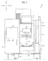
- a machine tool 30 of the present embodiment is a five-axis machine tool, and as illustrated in FIG. 1 , includes an apparatus body 31, a splash guard 33 that surrounds the apparatus body 31, and an operation panel 14.
- the components of the operation panel 14 that are the same as or equivalent to those described in the aforementioned related-art example are designated by the same reference numerals.
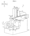
- a plurality of linear guide rails 34 are respectively provided parallel to each other in an X axis direction, that is, a left-right direction of the machine, on an upper surface of a rear portion of a bed 32 of the apparatus body 31.
- the linear guide rails 34 are engaged with linear guide blocks 35 provided on a lower surface of a saddle 36, and the saddle 36 is guided by the linear guide rails 34, such that the saddle 36 is movable in the X axis direction.
- the lower surface of the saddle 36 is mounted with a ball screw nut (not illustrated), and the ball screw nut is screwed to a ball screw shaft (not illustrated) provided at the bed 32.
- the saddle 36 is reciprocally movable in the X axis direction by the ball screw shaft being normally and reversely rotated by an X axis drive motor Mx (illustrated in FIG. 4 ) that is provided at the bed 32.
- a plurality of linear guide rails 38 are respectively provided parallel to each other in a Y axis direction, that is, a front-back direction of the machine, on an upper surface of the saddle 36.
- the linear guide rails 38 are engaged with linear guide blocks 41 provided on a lower surface of a column 40, and the column 40 is guided by the linear guide rails 38 such that the column 40 is movable in the Y axis direction.
- the lower surface of the column 40 is mounted with a ball screw nut (not illustrated), and the ball screw nut is screwed to a ball screw shaft (not illustrated) that is provided at the saddle 36.
- the column 40 is reciprocally movable in the Y axis direction by the ball screw shaft being normally and reversely rotated by a Y axis drive motor My (illustrated in FIG. 4 ) that is provided at the saddle 36.
- a plurality of linear guide blocks 42 are respectively provided parallel to each other in a Z axis direction, that is, an up-down direction of the machine, on the side surfaces of the column 40 on a front side.
- Linear guide rails 44 are engaged with the linear guide blocks 42.
- the linear guide rails 44 are provided on a side surface of a tool spindle head 46 on the column side, are guided by the linear guide blocks 42, and are movable in the Z axis direction.
- a ball screw nut (not illustrated) is provided on the side surface of the tool spindle head 46 on the column side, and the ball screw nut is screwed to a ball screw shaft (not illustrated) that is provided at the column 40.
- the tool spindle head 46 is reciprocally movable in the Z axis direction by the ball screw shaft being normally and reversely rotated by a Z axis drive motor Mz (illustrated in FIG. 4 ) that is provided at the column 40.
- the tool spindle head 46 includes a built-in type tool spindle motor Ms (refer to FIG. 4 ), and a spindle 47 is capable of being rotatably driven by the tool spindle motor Ms.
- a machining tool 48 for performing milling is attachable to the spindle 47.
- the saddle 36, the column 40, and the tool spindle head 46 are an example of a tool attachment device.
- a table 50 formed in the shape of a disk is provided on the bed 32.
- the table 50 is a tilt type rotary table.
- a table supporting base 54 is supported in a rotatable manner around an A axis by a supporting member 52 supported on the bed 32, and the table 50 is provided on the table supporting base 54 in a rotatable manner around a C axis orthogonal to the A axis.
- the table supporting base 54 is rotatable in a +A-direction and a -A-direction around the A axis by an A axis drive motor Ma (refer to FIG. 4 ), provided at the supporting member 52, being normally and reversely rotated.
- the table 50 is rotatable in a +C-direction and a -C-direction around the C axis by a C axis drive motor Mc (refer to FIG. 4 ), provided at the table supporting base 54, being normally and reversely rotated.
- Mc C axis drive motor
- a space where the machining tool 48 machines a workpiece with the respective operations of the saddle 36, the column 40, and the tool spindle head 46 that are the tool attachment device is referred to as a machining area 70.
- the supporting member 52, the table supporting base 54, and the table 50 are an example of the workpiece attachment device.
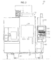
- the splash guard 33 provided on the front side of the apparatus body 31 is provided with an opening 33a, and a door 37, which opens and closes the opening 33a, is provided in an openable and closable manner at the splash guard 33. That is, the door 37 is provided so as to be slidable in a lateral direction between a closed position where the opening 33a illustrated in FIG. 2 is closed and an open position illustrated in FIG. 1 . If the door 37 is opened, a worker can access to the machining area 70 through the opening 33a.
- the splash guard 33 provided on the front side of the apparatus body 31 has functions of splash prevention and collection of chips or coolant generated in the machining area 70.
- the door 37 is provided with a window 39.
- the window 39 is fitted by a transmissive display device 60.
- a transmissive liquid crystal panel or a transmissive organic EL panel is used as the transmissive display device 60.
- the transmissive display device 60 is a hardware example of the manual operation auxiliary display unit.
- the transmissive display device 60 is a flat display that has a transparent display surface 60a so that the machining area 70 can be seen through. Additionally, as illustrated in FIG. 5 , the display surface 60a is formed in a quadrangular planar shape in the present embodiment, and has display areas 60b, 60c, and 60d at its periphery and corners where information, including characters, images, or moving images is displayed.
- the worker can monitor the machining of a workpiece, the operation of the machining tool 48, or the like in the machining area 70 through the transmissive display device 60 of the window 39.
- the operation panel 14 is rotatably supported via a bracket 62 adjacent to the opening 33a with respect to the splash guard 33 provided on the front side.
- the operation panel 14 includes an operation surface 14a, a display 14b made of a liquid crystal display or the like, and an input key group 14c.
- the operation surface 14a is provided with automatic operation mode buttons 15 of a tape operation mode button 15a, a memory operation mode button 15b, and an MDI operation mode button 15c, manual operation mode buttons 16 of manual pulse mode buttons 16a, a jog mode button 16b, a rapid mode button 16c, an origin return mode button 16d, and various axis selection buttons 20 to 29 to be used in manual operation modes.
- the buttons 15a to 15c, 16a to 16d, and 20 to 29 are self-return type pushbutton switches, and are binary switches that generate binary signals of an ON signal at an ON position where the buttons are pushed into the operation panel from the operation surface 14a as illustrated in FIG. 9(b) and an OFF signal at an OFF position where the buttons protrude further toward the outside of the operation panel than the ON position as illustrated in FIG. 9(a) .
- Each of the axis selection buttons 20 to 29 specifies an axis to be operated in the manual operation modes, and outputs a command to perform the axial movement.
- the axial movement can be performed to the corresponding axis.
- the operation surface 14a is provided with a handle 165 of a manual pulse generator 162, an axis selection dial 166, a rapid feed rate adjustment switch 167, and a jog feed rate adjustment switch 168.
- the handle 165 of the manual pulse generator 162 is a dial type handle for generating the movement distance of an axis.
- One pulse can be generated by rotating the dial type handle by one graduation.
- a pulse train of which the signs are inverted can be generated, and axes can be moved in a plus (+) direction or a minus (-) direction.
- the manual pulse generator 162 is an example of an axial movement command signal generator, and the pulse is an example of an axial movement command signal.
- the axis selection dial 166 is a dial type switch for selecting a target axis of which the axial movement is performed in a manual pulse mode. Specifically, OFF, X, Z, C, Y, and A are marked at every predetermined angle on the operation surface 14a, and a target axis of which the axial movement is performed in a manual pulse mode is selected by matching a pointer on the dial 166 with any one of positions where X, Z, C, Y, and A are marked.
- the rapid feed rate adjustment switch 167 which is a dial type switch, is provided for selecting a rapid feed override by which a rapid feed rate is multiplied, that is, a multiplying factor, in a case where the axis selection buttons 20 to 29 are ON-operated in the rapid mode and the origin return mode or at the time of a positioning operation (G00) to be executed in the automatic operation modes.
- the jog feed rate adjustment switch 168 which is a dial type switch, is provided for selecting a jog feed rate in the case that the axis selection buttons 20 to 29 are ON-operated in a jog mode or for selecting a cutting feed override by which a cutting feed rate that is commanded in a machining program in the automatic operation modes is multiplied.
- the automatic operation mode buttons 15 are buttons for changing the machine tool 30 into the various automatic operation modes in a case where being ON-operated. There are a tape operation mode in which operations are executed according to a machining program from the outside via an input interface (not illustrated), a memory operation mode in which operations are executed according to a machining program stored in a machining program memory 120 of a CNC control device 100 to be described below, and a MDI (manual data input) operation mode in which a worker inputs a single execution code on the spot from the operation panel and the operation is executed according to the input code, but the description thereof will be omitted herein.
- a tape operation mode in which operations are executed according to a machining program from the outside via an input interface (not illustrated)
- a memory operation mode in which operations are executed according to a machining program stored in a machining program memory 120 of a CNC control device 100 to be described below
- MDI manual data input
- the manual pulse mode buttons 16a are mode selection buttons for setting manual pulse modes. There are four manual pulse mode buttons 16a, and the respective mode buttons are provided in order to select a movement distance per one pulse of pulses generated by the manual pulse generator 162 from four types of 0.0001 mm, 0.001 mm, 0.01 mm, and 0.1 mm.
- the jog mode button 16b is a mode selection button for performing an axial movement at a jog feed using the axis selection buttons 20 to 29.
- a movement speed is based on the selection of the jog feed rate adjustment switch 168.
- the rapid mode button 16c is a mode selection button for performing an axial movement at a rapid feed using the axis selection buttons 20 to 29.
- a movement speed is based on the selection of the rapid feed rate adjustment switch 167.
- the origin return mode button 16d is a mode selection button that selects an origin return mode in which an axial movement to the origin position of an axis using the axis selection buttons 20 to 29.
- a movement speed is based on the selection of the rapid feed rate adjustment switch 167.
- the input key group 14c provided at the operation surface 14a includes various keys, such as a keyboard for data input, and ten keys, and function keys.
- the automatic operation mode buttons 15 and the manual operation mode buttons 16 are an example of a mode selecting unit.
- the axis selection buttons 20 to 29 and the axis selection dial 166 are examples of axis selection switches.
- the door 37 and the splash guard 33 that are located on the front side of the apparatus body 31 are an example of a cover portion.
- the machine tool 30 is provided with the CNC control device 100 illustrated in FIG. 4 .
- the CNC control device 100 has a main control unit 110 made of a CPU.
- a machining program memory 120 in which a machining program is stored, a system program memory 130 in which a program for an overall system is stored, a working memory 140, a machining control unit 150, a display data memory 170, a display controller 172 that performs the display control of the display 14b, a display controller 174 that performs the display control of the transmissive display device 60, an interface 164 electrically connected to the operation panel 14 and the manual pulse generator 162, and the like are connected to the main control unit 110 via a bus line 105.
- the various signals generated by the operation of the various buttons and the switches provided on the operation surface 14a of the operation panel 14 are input to the main control unit 110 via the interface 164. Additionally, the pulse signal generated by the manual pulse generator 162 is also input to the main control unit 110 via the interface 164.
- Various kinds of display data for displaying on the display 14b and the transmissive display device 60, respectively, are stored in the display data memory 170. Symbols for indicating the directions of axes, various kinds of warning display data, various kinds of prohibition display data, display data showing the state of the current machine tool, display data that prompts a worker to perform various kinds of operations, and the like are included in the display data for displaying on the transmissive display device 60.
- the display controller 172 performs the display control of the display 14b of the operation panel 14, and is widely known for NC machine tools, the detailed description thereof will be omitted.
- the display controller 174 performs the display control of the transmissive display device 60 to display the various kinds of display data stored in the display data memory 170 on the display areas in a case where the machine tool is operated in the manual operation modes.
- an X axis control unit 200, a Y axis control unit 210, a Z axis control unit 220, an A axis control unit 230, a C axis control unit 240, and a spindle control unit 250 are connected to the main control unit 110 via the bus line 105.
- the respective axis control units receive movement commands for respective axes (five axes) from the main control unit 110 and output the movement commands for the respective axes to drive circuits 202, 212, 222, 232, 242, and 252.
- the respective drive circuits receive the movement commands, and drive the motors Mx, My, Mz, Ma, Mc, and Ms for the respective axes (X, Y, Z, A, C, and tool spindle).
- the main control unit 110 is an example of a control unit that performs axial movements.
- an ON signal of the selected manual operation mode button is input to the main control unit 110 via the interface 164 illustrated in FIG. 4 .
- the main control unit 110 is switched to the selected manual operation mode, and transmits the ON signal to the display controller 174.
- the display controller 174 reads axis configuration display data, which is data for display of an axis configuration model 179 showing the directions of the axes of the machine tool, from the display data memory 170, and as illustrated in FIG. 5 , displays the axis configuration display data on the display area 60b at a corner in the display surface 60a of the transmissive display device 60.
- the axis configuration model 179 as illustrated in FIG.
- axis names and directions, +X, -X, +Y, -Y, +Z, -Z, +A, -A, +C, and -C are applied to the respective axes.
- the display controller 174 performs the display of "HANDLE MODE", "JOG MODE”, “RAPID MODE”, or "ORIGIN RETURN MODE” according to the ON signal, that is, the ON signal of the selected manual operation mode, in order to show the manual operation mode in an upper area of the axis configuration model 179.
- the display of "HANDLE MODE” is performed by the ON operation of the buttons 16a(1) to 16a(4)
- the display of "JOG MODE” is performed by the ON operation of the button 16b
- the display of the "RAPID MODE” is performed by the ON operation of the button 16c
- the display of the "ORIGIN RETURN MODE” is performed by the ON operation of the button 16d.
- the movement distance per one pulse based on an input manual operation mode signal in the case of a manual pulse mode, the jog feed rate selected by the jog feed rate adjustment switch 168 in the case of the jog mode, and a rapid feed override value selected by the rapid feed rate adjustment switch 167 in the case of the rapid mode and the origin return mode are respectively displayed in a lower display area of the axis configuration model 179.
- a signal selected by the jog feed rate adjustment switch 168 and a signal selected by the rapid feed rate adjustment switch 167, which have been input from the operation panel 14 via the interface 164 to the main control unit 110, are transmitted from the main control unit 110 to the display controller 174.
- the configuration of the axes included in the machine tool is displayed on the window 39 if selecting a manual operation mode is performed.
- a worker can confirm which axis is an axis for an axial movement and its direction, by comparing the posture of an actual machine or workpiece to the configuration of the axes, the direction of the axis can be determined without mistake.
- the worker M confirms the axis names and directions in the axis configuration model 179 displayed on the window.
- the worker does not concern over the operation, and the possibility of erroneous operation also becomes extremely low.
- the axis selection buttons 20 to 29 illustrated in FIG. 7(a) are switches that perform an axial movement in the jog mode, the rapid mode, and the origin return mode.
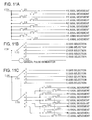
- An example of an interface circuit is illustrated in FIG. 11(a) .
- An axial movement is performed by signals +X, -X, +Y, -Y, +Z, -Z, +A, -A, +C, and -C that are output from the axis selection buttons 20 to 29.
- the main control unit 110 specifies an axis and a direction that are specified on the basis of a signal from an axis selection button and outputs the specified result to the display controller 174, if any one of the axis selection buttons 20 to 29 is operated to the ON position by the worker M illustrated in FIG. 9(b) .
- the display controller 174 highlights an arrow for the direction of the specified axis, that is, a movement direction of the axis. In a case where the arrow for the direction of the axis is highlighted, a half of the specified axis is highlighted, which indicates the specified direction of the arrow.
- An example of display in a case where a +Z axis selection button 24 is pushed in the rapid mode is illustrated in FIG. 8 .
- any one arrow indicating a specified direction is highlighted.
- the method of the highlighting is not limited, for example, a portion that is not highlighted is displayed with an inconspicuous color, whereas a portion to be highlighted is displayed with a conspicuous color. Otherwise, the portion to be highlighted is displayed by blinking, and the portion that is not highlighted is displayed by light reduction. Otherwise, the portion to be highlighted is displayed with a high degree of brightness, and the portion that is not highlighted is displayed with a low degree of brightness.
- the main control unit 110 controls axial movement of an axis specified by the axis selection button, at a jog feed rate selected by the jog feed rate adjustment switch 168 or with a multiplying factor selected by the rapid feed rate adjustment switch 167, that is, a rapid feed override.
- a jog feed rate selected by the jog feed rate adjustment switch 168 or with a multiplying factor selected by the rapid feed rate adjustment switch 167, that is, a rapid feed override.
- the machine tool configured as described above includes the transmissive display device 60 that highlights the movement directions of the axes specified by the operated axis selection buttons 20 to 29 on the window 39. Keeping pushing the axis selection buttons 20 to 29 makes first the specified movement direction of the axis be highlighted, and makes axial movement start after a predetermined time.
- the predetermined time is a time based on a value that is input to and stored in a memory in advance, and is changeable.
- the worker is able to acquire information on the movement directions of the axis selection buttons 20 to 29 without changing the direction of his/her eyes, and even if the buttons are erroneously operated, the worker can be aware of the erroneous operation and stop the operation before axial movement is actually performed.
- the axis selection buttons 20 to 29 are the binary switches.
- self-return type ternary switches may be used instead of the binary switches.
- the ternary switches are capable of taking three positions. These positions are an OFF position, a first ON position where an operation position is at a height lower than the OFF position, that is, a shallow operation position, and a second ON position where the operation position is at a height further lower than the first ON position, that is, a deep operation position.
- the display controller 174 highlights an arrow indicating an axial movement direction of an axis specified by the operated button of the axis selection buttons 20 to 29, on the basis of an ON signal generated at the first ON position.
- the main control unit 110 operates a drive motor, that is, starts axial movement of an axis selected by the operated button of the axis selection buttons 20 to 29, on the basis of an ON signal generated at the second ON position by the operated button of the axis selection buttons 20 to 29.
- the movement directions of the axes can be highlighted and the worker can intentionally adjust the delay time of actual axial movement depending on the intensity of pushing forces with which the axis selection buttons 20 to 29 are operated, in the jog mode, the rapid mode, or the origin return mode.
- a worker who is not yet experienced in machine operation can strongly push an axis selection button to perform an axial movement after the worker first pushes the button lightly and confirms the movement direction of the axis, and can safely and comfortably perform an axial movement operation.
- a worker experienced in the operation of the machine can strongly push an axis selection button from the start, thereby axial movement is quickly performed.
- the manual pulse generator 162 illustrated in FIG. 7(a) is an axial movement command signal generator.
- the manual pulse generator 162 is operated in a manual pulse mode to perform an axial movement.
- a target axis of which an axial movement is performed is selected by the axis selection dial 166 that is an axis selection switch.
- An example of an interface circuit is illustrated in FIG. 11(b) .
- an axis selected by the axis selection dial 166 is highlighted in the axis configuration model 179.
- the main control unit 110 specifies an axis selected by the axis selection dial 166 on the basis of the signal from the axis selection dial 166, and outputs the specified result to the display controller 174.
- the display controller 174 highlights the axis selected by the axis selection dial 166. Since the highlighting method is the same as that of the jog mode or the like except for a portion to be highlighted that will be described below, the description thereof will be omitted.
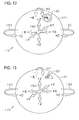
- the arrow of the direction of the axis selected as illustrated in FIG. 8 that is, an arrow of a specific direction of a specific axis is highlighted.
- the overall arrow of the axis selected as illustrated in FIG. 6 that is, both the plus (+) direction and the minus (-) direction of the selected axis are highlighted.
- the same axis selection dial 169 as that in the manual pulse modes as illustrated in FIG. 7(b) may be included as an axis selection switch in the jog mode, the rapid mode, and the origin return mode, and a plus (+) direction button 160 and a minus (-) direction button 161 are included as axial movement command signal generators so that an axial movement can be performed by pushing a button of a plus (+) direction or a minus (-) direction after selecting the target axis in a manual operation mode.
- an axis selected by the axis selection switch can be highlighted while any mode of the jog mode, the rapid mode, and the origin return mode is selected.
- An example of an interface circuit in this case is illustrated in FIG. 11(c) .
- an axis selected by the axis selection switch is highlighted on the window. Therefore, a worker can confirm whether or not the axis selected by the axis selection switch is an axis intended by the worker before the axial movement is operated.
- the main control unit 110 performs prohibition display or warning display in a case where there is a certain hindrance as follows in the manual pulse modes and the other manual operation modes.
- a mechanical origin is set to stroke ends in plus (+) directions in the case of X, Y, and Z axes that are linear axes, and minus (-) zone of the respective axes also serve as machining areas. That is, movement in the plus (+) directions from an origin position of the respective linear axes is prohibited, and interlock for axial movement prohibition is applied. Additionally, even in rotational axes, stroke ends in plus (+) directions and minus (-) directions are set, and interlock for axial movement prohibition is applied to outward directions from the stroke ends.
- the display controller 174 reads prohibition display symbolic data from the display data memory 170, and as illustrated in FIG. 12 , displays a prohibition display symbol 185 representing prohibition in the vicinity of an arrow head portion indicating an axial movement direction. That is, the display controller displays an axial movement prohibition state regarding the direction of an axis to which interlock is applied.
- FIG. 12 The example of FIG.
- the stroke end is not limited to the mechanical origin. It is needless to say that, even in a case where a point other than the mechanical origin is used as the stroke end, axial movement is prohibited and axial movement prohibition is displayed with respect to a direction out of an effective stroke at the stroke end.
- the machine tool in which automatic tool exchange (ATC) is executed out of a machining area, the machine tool is configured so that the movement of any one axis of the X axis, the Y axis, and the Z axis to an ATC position is allowed only while the ATC is executed.
- an ATC cover is provided so that cutting chips or a coolant is not splashed out of the machining area.
- An ATC standby position of any one axis of the X axis, the Y axis, and the Z axis is set at a stroke end nearest to the ATC position out of the machining area.
- the machine tool of the present embodiment is equipped with the barrier function.
- the operation panel 14 is provided with the input key group 14c for inputting models of respective constituent members mentioned in the examples of the tool attachment device and the workpiece attachment device as the barrier zone.
- the input key group 14c is an example of means to input models as the barrier zone, and the means is not limited to the input key group 14c.
- the main control unit 110 is capable of executing an axial movement simulation with an internal model for a set barrier zone not only in the automatic operation modes but also in the manual operation modes, and avoiding an interference.
- the main control unit 110 is configured so that, if the tool attachment device enters a slow-moving zone set right before the set barrier zone, the tool attachment device is reduced in speed and slowly moved and is stopped on the boundary line of the barrier zone.
- the slow-moving zone is set as a slow-moving distance with a parameter. If the tool attachment device rushes into this slow-moving zone, the main control unit 110 controls the movement of the tool attachment device at the lower one of speed sets by the rapid feed rate adjustment switch 167 or the jog feed rate adjustment switch 168, and a slow-moving speed in the slow-moving zone. Thus, this gives operational discomfort to a worker.
- the main control unit 110 outputs a warning display showing that the tool attachment device is located in the slow-moving zone, that is, the tool attachment device is moving slowly, to the display controller 174.
- the display controller 174 reads warning display symbol data from the display data memory 170, and displays the warning display symbol in the vicinity of an arrow head portion indicating an axial movement direction.
- FIG. 13 is an example in which, in a case where axial movement to +A is performed, a warning display symbol 186 for slow movement is displayed in the vicinity of the +A.
- the axial movement simulation is performed with the model inside the control unit, and if the tool attachment device enters the slow-moving zone set right before the barrier zone, the tool attachment device is reduced in speed and slowly moved and is stopped on the boundary line of the barrier zone.
- the axial movement simulation may be performed with the model inside the control unit, and if the workpiece attachment device enters the slow-moving zone set right before the barrier zone, the workpiece attachment device may be slowly moved after reduction in speed and be stopped on the boundary line of the barrier zone.
- the axial movement simulation may be performed with the model inside the control unit, and if at least one of the tool attachment device and the workpiece attachment device similarly enters the slow-moving zone set right before the barrier zone, such device may be slowly moved after reduction in speed and be stopped on the boundary line of the barrier zone.
- an interlock function for the axial movement prohibition for example, speed is reduced slightly right before a stroke end, the axial movement is stopped at the stroke end, and the interlock state of the axial movement prohibition is brought about.
- the above warning display may be performed even during the speed reduction.
- the arrows indicating the directions of the axes included in the machine tool are displayed as an axis configuration model 179. Accordingly, by comparing the posture of the actual machine to the axis configuration model, the worker can intuitively understand an axis and a moving direction in a case where an axial movement operation is performed in the manual operation modes.
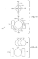
- an axis configuration model 198 may be constituted of a tool spindle symbol 190, an arrow 191 indicating the movement direction of the tool spindle symbol 190 on the X axis and the Y axis, a table symbol 192, a symbol 193 for a supporting member that supports the table supporting base, and arrows 194, 195, 196, and 197 indicating the movement directions of the A axis and the C axis, in a top plan view of a machine tool as illustrated in FIG. 14 .
- FIG. 15 is an example in which a case where the tool spindle symbol 190 moves in the +X axis direction is illustrated by animation. Accordingly, the axial movement direction of the tool spindle can be more intuitively understood.
- the display controller 174 may display a warning display symbol 187 representing that an alarm is generated, on the display area 60d at a corner of the display surface 60a.
- the display area is not limited to the display area 60d, and may be around the display surface 60a.
- a central portion of the display surface 60a may be used as the display area if the central portion does not become a hindrance when the inside of the machine is viewed.
- the display surface 60a has been described to have a quadrangular flat shape, the display surface 60a may be a quadrangular curved surface shape or may be a circular flat shape.
- the window 39 including the transmissive display device 60 is provided in the door 37.
- the window 39 may be provided at the splash guard 33 that covers the machining area 70. The same effects as those of the embodiment can be achieved even in this case.
- the invention has been implemented in the five-axis machine tool having the tilt type rotary table.
- the invention is not limited to the tilt type rotary table. It is also possible to implement the invention in other machine tools, such as three-axis or four-axis machine tools, or other types of five-axis machine.
- an XY table that is movable in the XY directions may be used as the table 50.
- the invention has been implemented in the machine tool that controls the axial movement of both the tool attachment device and the workpiece attachment device.
- the number of axes is five in the machine tool of the embodiment, the invention is not limited to this axis number.
- the transmissive display device 60 has been used as the manual operation auxiliary display unit.
- a projector type display device in which a half mirror is fitted into the window 39 and an image is projected on the half mirror may be provided instead of the transmissive display device 60, and an image indicating axial movement directions may be projected, that is, displayed on the half mirror in real time in the display device. Even in this case, the worker M can simultaneously view the machining area 70 and the image via the window.
Landscapes
- Engineering & Computer Science (AREA)
- Mechanical Engineering (AREA)
- Physics & Mathematics (AREA)
- General Physics & Mathematics (AREA)
- Automation & Control Theory (AREA)
- Human Computer Interaction (AREA)
- Manufacturing & Machinery (AREA)
- Numerical Control (AREA)
- Machine Tool Sensing Apparatuses (AREA)
Abstract
Description
- The present invention relates to a machine tool.
- In a conventional machine tool, as illustrated in
FIGs. 16(a) and 16(b) , a workpiece is machined by a tool attached to a tool spindle (not illustrated) in amachining area 13 that is covered with asplash guard 10 or the like. Thesplash guard 10 or the like is provided with awindow 11 into which atransparent plate 12 is fitted. A worker M is able to monitor themachining area 13 through thewindow 11. Additionally, anoperation panel 14 is rotatably supported on a part of thesplash guard 10 close to thewindow 11 so that the operation panel can be operated by the worker M who monitors the machining area through thewindow 11. Theoperation panel 14 is capable of being fixed at arbitrary angles within it's movable range by the worker M, such as a position where anoperation surface 14a of theoperation panel 14 faces a front side as illustrated inFIG. 16(b) , and in a direction in which theoperation surface 14a intersects thewindow 11 as illustrated inFIG. 17(b) , for example, a position where theoperation surface 14a is orthogonal to thefront splash guard 10. If theoperation panel 14 is rotatably provided in this way, the rotational position of theoperation panel 14 can be changed according to a worker's standing position. Therefore, there is an advantage that the operation of theoperation panel 14 can be performed without changing of the worker's standing position. - Additionally, as illustrated in
FIG. 7(a) , theoperation surface 14a of theoperation panel 14 is provided with automaticoperation mode buttons 15 and manualoperation mode buttons 16, and mode selection of an automatic operation mode or a manual operation mode is enabled by operating any one of these buttons. - A tape
operation mode button 15a, a memoryoperation mode button 15b, and MDI (a manual data input)operation mode button 15c are included in the automaticoperation mode buttons 15, and manualpulse mode buttons 16a, ajog mode button 16b, arapid mode button 16c, and an originreturn mode button 16d are included in the manualoperation mode buttons 16. Moreover, the manualpulse mode buttons 16a include a manual pulse 0.0001mm mode button 16a(1), a manual pulse 0.001mm mode button 16a(2), a manual pulse 0.01mm mode button 16a(3), and a manual pulse 0.1mm mode button 16a(4) for selecting a movement distance per one pulse of pulses generated from a manual pulse generator. Additionally, as illustrated inFIG. 7(a) , theoperation surface 14a of theoperation panel 14 is provided with variousaxis selection buttons 20 to 29 for manually operating respective axes of the machine tool. If any one of the axis selection buttons is operated, a constituent member of the machine tool can be moved in the direction of an axis corresponding to the axis selection button or can be rotated around the axis. For example, in an example illustrated inFIG. 7(a) , the axis selection buttons include a +Xaxis selection button 20, a -Xaxis selection button 21, a +Yaxis selection button 22, a -Yaxis selection button 23, a +Zaxis selection button 24, a -Zaxis selection button 25, a +Aaxis selection button 26, a -Aaxis selection button 27, a +Caxis selection button 28, and a -Caxis selection button 29. The +Xaxis selection button 20, as illustrated inFIG. 7(a) , is located on a right side as seen from the front, and the -Xaxis selection button 21 is located on a left side. - If a manual operation mode, for example, a jog mode is selected and the +X
axis selection button 20, or the -Xaxis selection button 21 is operated, it is possible to move the tool spindle or the table in a plus (+) direction or a minus (-) direction of the X axis. - Here, in a case where the
operation panel 14 faces a position illustrated inFIG. 16(b) , that is, theoperation surface 14a faces the front, an alignment of the +Xaxis selection button 20 and the -Xaxis selection button 21 coincides with that of the plus (+) direction and the minus (-) direction of the X axis of the machine tool. However, since the worker M is located near thewindow 11 side in order to monitor themachining area 13 and is away from theoperation surface 14a, it is difficult for him to perform a button operation of theoperation surface 14a. On the contrary, in a case where the worker M stands in front of theoperation surface 14a in order to perform an operation, there is a problem in that themachining area 13 is not easily be seen. - Meanwhile, in a case where the
operation panel 14 faces a position illustrated inFIGs. 17(a) and 17(b) , that is, is fixed at an angle where theoperation surface 14a intersects thewindow 11, theoperation surface 14a is located so as to face the worker M located near thewindow 11 side. Therefore, there is an advantage that the worker M easily performs the button operation of theoperation surface 14a while monitoring themachining area 13. - However, the alignment of the +X
axis selection button 20 and the -Xaxis selection button 21 of theoperation panel 14, as illustrated inFIG. 17(b) , does not coincide with that of the plus (+) direction and the minus (-) direction of the X axis in the machine tool. For this reason, a worker who is inexperienced in operation has a fear of an erroneous operation. - In addition, although it has been described about the alignment of the +X
axis selection button 20 and the -Xaxis selection button 21 as an example, there is another example in which the directions of the axes of the machine tool do not coincide with alignments of related buttons on the operation panel, and the above example is merely an example. In a machine tool having a configuration of a plurality of axes, the combination of the axes is three-dimensionally arranged, whereas theoperation surfaces 14a are two-dimensional. Therefore, it is necessary to virtually arrange alignment of the axis selection buttons. For example, in the example illustrated inFIG. 7(a) , the Y axis is a front-back direction of the machine tool, whereas the +Y axis selection button and the -Y axis selection button on theoperation surface 14a are arranged in an up-down direction. For this reason, a worker who is inexperienced in operation has a fear of performing an erroneous operation regarding the -Y axis and the +Y axis also. There may also be the problems as described above regarding other axis selection buttons. - In
PTL 1, a machining information projection device provided in a machine tool is proposed. The machining information projection device includes a half mirror, and display means for emitting light to display machining information. The half mirror is provided at a position where a machining area of the machine tool is capable of being monitored and where an image emitted from the display means is reflected on a worker, and further is provided so that a portion of the incident light from the machining area is transmitted therethrough to the worker side. In the machining information projection device, the worker can simultaneously view an image of the machining information emitted from the display means and reflected by the half mirror, and an actual image of the machining area that is visible through the half mirror. - However, in
PTL 1, only the machining information in automatic operation is displayed.PTL 1 does not disclose the above problems and the means for solving the problems, in a case where a manual operation mode is selected in order to manually operate the machining tool. - PTL 1: Japanese Laid-open Patent Publication No.
11-156677 - An object of the invention is to provide a machine tool that can avoid a worker's erroneous operation of the axis selection button by means of displaying the movement direction of an axis selection button on a window provided in order for the worker to monitor a machining area of a machine tool in a case where being operated in a manual operation mode.
- In order to solve the above-described problem, a machine tool according to the invention includes a tool attachment device to which a machining tool is to be mounted; a workpiece attachment device to which a workpiece to be mounted, the workpiece is machined by the machining tool; a control unit configured to control the axial movements of at least one of the tool attachment device and the workpiece attachment device; a mode selecting unit configured to select a manual operation mode or an automatic operation mode; an axis selection switch to select a target axis for the axial movement by the control unit in a case where the manual operation mode is selected; a cover portion to cover a machining area in which the machining tool is to machine the workpiece; a window provided in the cover portion through which the machining area are monitored; and the machine tool further comprises a manual operation auxiliary display unit configured to display directions of the plurality of axes included in the machine tool as an axis configuration model in the window in a case where the manual operation mode is selected.
- According to this configuration, the worker is able to understand the movement direction of an axis in a case where the axis selection switch is operated, by comparing the positional relationship between respective constituent members inside the machine tool that are seen from the window to the axis configuration model, and is able to perform the operation of the axis correctly and quickly. As a result, an erroneous operation of the axis selection switch can be avoided, and a worker's burden can be made very small. Additionally, since the operation of the axis selection switch can be correctly and quickly performed, the machining time for a first article in which manual intervention is frequently performed can be shortened.
- Preferably, the machine tool further includes an axis selection button as the axis selection switch. The axis selection button specifies the target axis for the axial movement by the control unit, and outputs an axial movement command signal to the target axis. In the manual operation mode, the axial movements are performed based on the axial movement command signal from the axis selection button. In a case where the axis selection button is pushed in the manual operation mode, the manual operation auxiliary display unit highlights a movement direction with respect to the axis selected by the axis selection button in the axis configuration model, and the control unit performs the axial movement in a delayed manner from the highlighting of the movement direction by the manual operation auxiliary display unit.
- According to this configuration, in a case where the axis selection button is pushed in the manual operation mode, the axial movement is performed in a delayed manner after the highlighting of the axial movement direction is performed. For this reason, the worker can stop the operation of the axis selection switch during the delayed time, in a case where the movement direction highlighted in the axis configuration model is not the movement direction desired.
- Preferably, the axis selection button comprises a pushbutton switch that further outputs two different signals depending on push-in amounts other than an OFF signal. In a case where the axis selection button is pushed in the manual operation mode, the manual operation auxiliary display unit highlights a movement direction with respect to the axis specified by an output at a shallow operation position of the axis selection button in the axis configuration model, and the control unit performs the axial movement according to an output at a deep operation position of the axis selection button.
- According to this configuration, in a case where the axis selection button is operated in the manual operation mode, the movement direction of an axis is highlighted by operating the axis selection button with a light force at first, and then, the axial movement is performed by operating the axis selection button with a stronger force. For this reason, the worker does not further push in the axis selection switch, in a case where the movement direction of the highlighted axis is not the movement direction of a desired axis, such that the worker can avoid an erroneous operation of the axial movement.
- Preferably, the machine tool further includes an axial movement command signal generator configured to output an axial movement command signal in the manual operation mode. In the manual operation mode, the axial movements are performed based on the signal from the axial movement command signal generator with respect to the axis selected by the axis selection switch. In a case where the manual operation mode is selected, the manual operation auxiliary display unit highlights the axis selected by the axis selection switch in the axis configuration model.
- According to this configuration, since an axis selected by the axis selection switch is highlighted in the axis configuration model on the window, in a case where the manual operation mode is selected, the worker can confirm the axis selected by the axis selection switch before the axial movement is operated.
- Preferably, the control unit has an interlock function for prohibiting the axial movement of the at least one of the tool attachment device and the workpiece attachment device in a specific direction in a case where the at least one of the tool attachment device and the workpiece attachment device is located in a specific place, and the manual operation auxiliary display unit displays an axial movement prohibition state regarding a direction of an axis to which an axial movement of the at least one of the tool attachment device and the workpiece attachment device is prohibited in the axis configuration model.
- According to this configuration, since information is displayed on the window that an axis is in the axial movement prohibition state regarding the axis, which is interlocked as axial movement prohibition state, the worker can know that the axis to be operated by the axis selection switch is in the axial movement prohibition state, before he actually operates it.
- Preferably, the machine tool further includes means for inputting respective models of the tool attachment device and the workpiece attachment device as a barrier zone, and a barrier function which performs a movement simulation with a model inside the control unit, performs slow movement after speed reduction in a slow-moving zone right before the barrier zone, and performs a stop at a boundary line of the barrier zone so that no interference accompanying an axial movement occurs, in a case where at least any one of the tool attachment device and the workpiece attachment device is operated in the manual operation mode. The manual operation auxiliary display unit displays in the axis configuration model, a slow-moving state regarding a direction for slow movinge in which any device is located in the slow-moving zone.
- According to this configuration, since the slow-moving state is displayed, the worker can perform an operation without discomfort even if movement is performed not at a desired speed but at a slow-moving speed. Additionally, the worker can easily know an avoidance direction of an interference by knowing a slow-moving direction.
- Preferably, the axis configuration model displays an arrow indicating the direction of the axis.
- According to this configuration, since the manual operation auxiliary display unit shows the direction of the axis with the arrow, the worker can perform an operation without mistaking about an axis or a moving direction.
- Preferably, the axis configuration model includes a symbol representing a movable constituent member of the machine tool, and an arrow indicating the movement direction of the constituent member.
- According to this configuration, since which constituent member moves in which direction is displayed clearly, erroneous operation in the axial movement of manual operation decreases.
- Preferably, the manual operation auxiliary display unit displays the symbol by animation by moving the symbol toward a movement direction.
- According to this configuration, since the manual operation auxiliary display unit displays the symbol by animation to be moved toward the movement direction, it is much easier to know which constituent member moves in which direction.
-
- [
FIG. 1] FIG. 1 is a front view of a machine tool in a door open state. - [
FIG. 2] FIG. 2 is a front view of the machine tool in a door closed state. - [
FIG. 3] FIG. 3 is perspective view of essential portions of the machine tool. - [
FIG. 4] FIG. 4 is a block diagram of a control device of the machine tool. - [
FIG. 5] FIG. 5 is a front view of a manual operation auxiliary display unit that is provided at a window. - [
FIG. 6] FIG. 6 is an explanatory view of a display aspect illustrating directions of axes. - [
FIG. 7 ] (a) is a front view of an operation surface of an operation panel, and (b) is a front view of part of an operation surface in another embodiment. - [
FIG.8] FIG. 8 is an explanatory view of a display aspect illustrating directions of axes. - [
FIG. 9 ] (a) is an explanatory view of the position of axis selection buttons in an OFF state, and (b) is an explanatory view of the position of the axis selection buttons in an ON state. - [
FIG. 10 ] (a) is an explanatory view of the position of axis selection buttons in an OFF state in another embodiment, (b) is an explanatory view of the position of the axis selection buttons in an ON state at a shallow operation position, and (c) is an explanatory view of the position of the axis selection buttons in an ON state at a deep operation position. - [
FIG. 11 ] (a) is an interface circuit diagram illustrating that axial movements are operated with axis selection buttons of an example, (b) is an interface circuit diagram illustrating that axial movements are operated with an axis selection dial and a manual pulse generator of the example, and (c) is an interface circuit diagram illustrating axial movements are operated with axis selection dials and axial buttons of another example. - [
FIG. 12] FIG. 12 is an explanatory view of a display aspect illustrating axis to which the axial movement prohibition is applied by means of the interlock function. - [
FIG. 13] FIG. 13 is an explanatory view of a display aspect illustrating axis that is slowly moving in a case where there is a concern of interference with other members due to axial movements. - [
FIG. 14] FIG. 14 is an explanatory view of a display aspect illustrating movement directions of axes in a case where a movable portion of the machine tool is simplified and viewed in a plan view. - [
FIG. 15] FIG. 15 is an explanatory view of a display aspect illustrating movement directions of axes by animating the movable portion, in a case where the movable portion of the machine tool is simplified and viewed in a plan view. - [
FIG. 16 ] (a) is a front view around a window of the machine tool in a case where the operation surface of the operation panel is directed to a front side, and (b) is a schematic plan view around the window in the same case ofFig.16 (a) . - [
FIG. 17 ] (a) is a front view around the window of the machine tool in a case where the operation surface of the operation panel is directed perpendicularly to the window, and (b) is a schematic plan view around the window in the same case ofFig.17 (a) . - Hereinafter, an embodiment of a machine tool in which the present invention is embodied will be described with reference to
FIGs. 1 to 15 . - A
machine tool 30 of the present embodiment is a five-axis machine tool, and as illustrated inFIG. 1 , includes anapparatus body 31, asplash guard 33 that surrounds theapparatus body 31, and anoperation panel 14. In addition, the components of theoperation panel 14 that are the same as or equivalent to those described in the aforementioned related-art example are designated by the same reference numerals. - As illustrated in
FIG. 3 , a plurality oflinear guide rails 34 are respectively provided parallel to each other in an X axis direction, that is, a left-right direction of the machine, on an upper surface of a rear portion of abed 32 of theapparatus body 31. Thelinear guide rails 34 are engaged with linear guide blocks 35 provided on a lower surface of asaddle 36, and thesaddle 36 is guided by thelinear guide rails 34, such that thesaddle 36 is movable in the X axis direction. In addition, the lower surface of thesaddle 36 is mounted with a ball screw nut (not illustrated), and the ball screw nut is screwed to a ball screw shaft (not illustrated) provided at thebed 32. Thesaddle 36 is reciprocally movable in the X axis direction by the ball screw shaft being normally and reversely rotated by an X axis drive motor Mx (illustrated inFIG. 4 ) that is provided at thebed 32. - A plurality of
linear guide rails 38 are respectively provided parallel to each other in a Y axis direction, that is, a front-back direction of the machine, on an upper surface of thesaddle 36. Thelinear guide rails 38 are engaged with linear guide blocks 41 provided on a lower surface of acolumn 40, and thecolumn 40 is guided by thelinear guide rails 38 such that thecolumn 40 is movable in the Y axis direction. In addition, the lower surface of thecolumn 40 is mounted with a ball screw nut (not illustrated), and the ball screw nut is screwed to a ball screw shaft (not illustrated) that is provided at thesaddle 36. Thecolumn 40 is reciprocally movable in the Y axis direction by the ball screw shaft being normally and reversely rotated by a Y axis drive motor My (illustrated inFIG. 4 ) that is provided at thesaddle 36. - A plurality of linear guide blocks 42 are respectively provided parallel to each other in a Z axis direction, that is, an up-down direction of the machine, on the side surfaces of the
column 40 on a front side. Linear guide rails 44 are engaged with the linear guide blocks 42. The linear guide rails 44 are provided on a side surface of atool spindle head 46 on the column side, are guided by the linear guide blocks 42, and are movable in the Z axis direction. A ball screw nut (not illustrated) is provided on the side surface of thetool spindle head 46 on the column side, and the ball screw nut is screwed to a ball screw shaft (not illustrated) that is provided at thecolumn 40. Thetool spindle head 46 is reciprocally movable in the Z axis direction by the ball screw shaft being normally and reversely rotated by a Z axis drive motor Mz (illustrated inFIG. 4 ) that is provided at thecolumn 40. - The
tool spindle head 46 includes a built-in type tool spindle motor Ms (refer toFIG. 4 ), and aspindle 47 is capable of being rotatably driven by the tool spindle motor Ms.A machining tool 48 for performing milling is attachable to thespindle 47. - The
saddle 36, thecolumn 40, and thetool spindle head 46 are an example of a tool attachment device. - A table 50 formed in the shape of a disk is provided on the
bed 32. The table 50 is a tilt type rotary table. Atable supporting base 54 is supported in a rotatable manner around an A axis by a supportingmember 52 supported on thebed 32, and the table 50 is provided on thetable supporting base 54 in a rotatable manner around a C axis orthogonal to the A axis. Thetable supporting base 54 is rotatable in a +A-direction and a -A-direction around the A axis by an A axis drive motor Ma (refer toFIG. 4 ), provided at the supportingmember 52, being normally and reversely rotated. The table 50 is rotatable in a +C-direction and a -C-direction around the C axis by a C axis drive motor Mc (refer toFIG. 4 ), provided at thetable supporting base 54, being normally and reversely rotated. - A space where the
machining tool 48 machines a workpiece with the respective operations of thesaddle 36, thecolumn 40, and thetool spindle head 46 that are the tool attachment device is referred to as amachining area 70. Additionally, the supportingmember 52, thetable supporting base 54, and the table 50 are an example of the workpiece attachment device. - As illustrated in
FIG. 1 , thesplash guard 33 provided on the front side of theapparatus body 31 is provided with an opening 33a, and adoor 37, which opens and closes the opening 33a, is provided in an openable and closable manner at thesplash guard 33. That is, thedoor 37 is provided so as to be slidable in a lateral direction between a closed position where the opening 33a illustrated inFIG. 2 is closed and an open position illustrated inFIG. 1 . If thedoor 37 is opened, a worker can access to themachining area 70 through the opening 33a. - The
splash guard 33 provided on the front side of theapparatus body 31 has functions of splash prevention and collection of chips or coolant generated in themachining area 70. - The
door 37 is provided with awindow 39. Thewindow 39 is fitted by atransmissive display device 60. A transmissive liquid crystal panel or a transmissive organic EL panel is used as thetransmissive display device 60. Thetransmissive display device 60 is a hardware example of the manual operation auxiliary display unit. - The
transmissive display device 60 is a flat display that has atransparent display surface 60a so that themachining area 70 can be seen through. Additionally, as illustrated inFIG. 5 , thedisplay surface 60a is formed in a quadrangular planar shape in the present embodiment, and hasdisplay areas - The worker can monitor the machining of a workpiece, the operation of the
machining tool 48, or the like in themachining area 70 through thetransmissive display device 60 of thewindow 39. - A method for displaying various kinds of information in the
transmissive display device 60 will be described below. - As illustrated in
FIGs. 1 and2 , theoperation panel 14 is rotatably supported via abracket 62 adjacent to the opening 33a with respect to thesplash guard 33 provided on the front side. Theoperation panel 14 includes anoperation surface 14a, adisplay 14b made of a liquid crystal display or the like, and an inputkey group 14c. - As illustrated in
FIG. 7(a) , theoperation surface 14a is provided with automaticoperation mode buttons 15 of a tapeoperation mode button 15a, a memoryoperation mode button 15b, and an MDIoperation mode button 15c, manualoperation mode buttons 16 of manualpulse mode buttons 16a, ajog mode button 16b, arapid mode button 16c, an originreturn mode button 16d, and variousaxis selection buttons 20 to 29 to be used in manual operation modes. Thebuttons 15a to 15c, 16a to 16d, and 20 to 29 are self-return type pushbutton switches, and are binary switches that generate binary signals of an ON signal at an ON position where the buttons are pushed into the operation panel from theoperation surface 14a as illustrated inFIG. 9(b) and an OFF signal at an OFF position where the buttons protrude further toward the outside of the operation panel than the ON position as illustrated inFIG. 9(a) . - Each of the
axis selection buttons 20 to 29 specifies an axis to be operated in the manual operation modes, and outputs a command to perform the axial movement. By pushing one of theaxis selection buttons 20 to 29 in a case where the jog mode, the rapid mode, or the origin return mode is selected, the axial movement can be performed to the corresponding axis. - The
operation surface 14a is provided with ahandle 165 of amanual pulse generator 162, anaxis selection dial 166, a rapid feedrate adjustment switch 167, and a jog feedrate adjustment switch 168. - The
handle 165 of themanual pulse generator 162 is a dial type handle for generating the movement distance of an axis. One pulse can be generated by rotating the dial type handle by one graduation. By rotating the dial type handle in left-right opposite directions, a pulse train of which the signs are inverted can be generated, and axes can be moved in a plus (+) direction or a minus (-) direction. Themanual pulse generator 162 is an example of an axial movement command signal generator, and the pulse is an example of an axial movement command signal. - The
axis selection dial 166 is a dial type switch for selecting a target axis of which the axial movement is performed in a manual pulse mode. Specifically, OFF, X, Z, C, Y, and A are marked at every predetermined angle on theoperation surface 14a, and a target axis of which the axial movement is performed in a manual pulse mode is selected by matching a pointer on thedial 166 with any one of positions where X, Z, C, Y, and A are marked. - The rapid feed
rate adjustment switch 167, which is a dial type switch, is provided for selecting a rapid feed override by which a rapid feed rate is multiplied, that is, a multiplying factor, in a case where theaxis selection buttons 20 to 29 are ON-operated in the rapid mode and the origin return mode or at the time of a positioning operation (G00) to be executed in the automatic operation modes. - The jog feed
rate adjustment switch 168, which is a dial type switch, is provided for selecting a jog feed rate in the case that theaxis selection buttons 20 to 29 are ON-operated in a jog mode or for selecting a cutting feed override by which a cutting feed rate that is commanded in a machining program in the automatic operation modes is multiplied. - The automatic
operation mode buttons 15 are buttons for changing themachine tool 30 into the various automatic operation modes in a case where being ON-operated. There are a tape operation mode in which operations are executed according to a machining program from the outside via an input interface (not illustrated), a memory operation mode in which operations are executed according to a machining program stored in amachining program memory 120 of aCNC control device 100 to be described below, and a MDI (manual data input) operation mode in which a worker inputs a single execution code on the spot from the operation panel and the operation is executed according to the input code, but the description thereof will be omitted herein. - The manual
pulse mode buttons 16a are mode selection buttons for setting manual pulse modes. There are four manualpulse mode buttons 16a, and the respective mode buttons are provided in order to select a movement distance per one pulse of pulses generated by themanual pulse generator 162 from four types of 0.0001 mm, 0.001 mm, 0.01 mm, and 0.1 mm. - The
jog mode button 16b is a mode selection button for performing an axial movement at a jog feed using theaxis selection buttons 20 to 29. A movement speed is based on the selection of the jog feedrate adjustment switch 168. - The
rapid mode button 16c is a mode selection button for performing an axial movement at a rapid feed using theaxis selection buttons 20 to 29. A movement speed is based on the selection of the rapid feedrate adjustment switch 167. - The origin
return mode button 16d is a mode selection button that selects an origin return mode in which an axial movement to the origin position of an axis using theaxis selection buttons 20 to 29. A movement speed is based on the selection of the rapid feedrate adjustment switch 167. - Additionally, the input
key group 14c provided at theoperation surface 14a includes various keys, such as a keyboard for data input, and ten keys, and function keys. - The automatic
operation mode buttons 15 and the manualoperation mode buttons 16 are an example of a mode selecting unit. Theaxis selection buttons 20 to 29 and theaxis selection dial 166 are examples of axis selection switches. - The
door 37 and thesplash guard 33 that are located on the front side of theapparatus body 31 are an example of a cover portion. - The
machine tool 30 is provided with theCNC control device 100 illustrated inFIG. 4 . TheCNC control device 100 has amain control unit 110 made of a CPU. Amachining program memory 120 in which a machining program is stored, asystem program memory 130 in which a program for an overall system is stored, a workingmemory 140, amachining control unit 150, adisplay data memory 170, adisplay controller 172 that performs the display control of thedisplay 14b, adisplay controller 174 that performs the display control of thetransmissive display device 60, aninterface 164 electrically connected to theoperation panel 14 and themanual pulse generator 162, and the like are connected to themain control unit 110 via abus line 105. - The various signals generated by the operation of the various buttons and the switches provided on the
operation surface 14a of theoperation panel 14 are input to themain control unit 110 via theinterface 164. Additionally, the pulse signal generated by themanual pulse generator 162 is also input to themain control unit 110 via theinterface 164. - Various kinds of display data for displaying on the
display 14b and thetransmissive display device 60, respectively, are stored in thedisplay data memory 170. Symbols for indicating the directions of axes, various kinds of warning display data, various kinds of prohibition display data, display data showing the state of the current machine tool, display data that prompts a worker to perform various kinds of operations, and the like are included in the display data for displaying on thetransmissive display device 60. - Since the
display controller 172 performs the display control of thedisplay 14b of theoperation panel 14, and is widely known for NC machine tools, the detailed description thereof will be omitted. - The
display controller 174 performs the display control of thetransmissive display device 60 to display the various kinds of display data stored in thedisplay data memory 170 on the display areas in a case where the machine tool is operated in the manual operation modes. - Additionally, an X
axis control unit 200, a Yaxis control unit 210, a Zaxis control unit 220, an Aaxis control unit 230, a Caxis control unit 240, and aspindle control unit 250 are connected to themain control unit 110 via thebus line 105. The respective axis control units receive movement commands for respective axes (five axes) from themain control unit 110 and output the movement commands for the respective axes to drivecircuits main control unit 110 is an example of a control unit that performs axial movements. - Next, the working of the
machine tool 30 configured as described above will be described. - Working common to the respective modes, in a case where mode change to one mode of the manual operation modes is performed, will be described.
- If a worker M ON-operates any of the manual operation mode buttons of a manual pulse 0.0001
mm mode button 16a (1), a manual pulse 0.001mm mode button 16a(2), a manual pulse 0.01mm mode button 16a(3), a manual pulse 0.1mm mode button 16a(4), thejog mode button 16b, therapid mode button 16c, and the originreturn mode button 16d illustrated inFIG. 7(a) , an ON signal of the selected manual operation mode button is input to themain control unit 110 via theinterface 164 illustrated inFIG. 4 . By means of the input of the ON signal, themain control unit 110 is switched to the selected manual operation mode, and transmits the ON signal to thedisplay controller 174. - By means of the input of the ON signal, the
display controller 174 reads axis configuration display data, which is data for display of anaxis configuration model 179 showing the directions of the axes of the machine tool, from thedisplay data memory 170, and as illustrated inFIG. 5 , displays the axis configuration display data on thedisplay area 60b at a corner in thedisplay surface 60a of thetransmissive display device 60. Theaxis configuration model 179, as illustrated inFIG. 6 , includes asymbol 180 for a rectangular coordinates axis in which respective plus (+) directions and minus (-) directions of the X axis, the Y axis, and the Z axis are arrowed, asphere 181 at the center of which thesymbol 180 is arranged,arrows sphere 181, and anarrow 184 indicating the movement direction about the A axis. Additionally, as illustrated inFIG. 6 , in theaxis configuration model 179, axis names and directions, +X, -X, +Y, -Y, +Z, -Z, +A, -A, +C, and -C are applied to the respective axes. - Additionally, although illustration is omitted for convenience of explanation in
FIG. 5 , as illustrated inFIG. 6 , thedisplay controller 174 performs the display of "HANDLE MODE", "JOG MODE", "RAPID MODE", or "ORIGIN RETURN MODE" according to the ON signal, that is, the ON signal of the selected manual operation mode, in order to show the manual operation mode in an upper area of theaxis configuration model 179. Namely, the display of "HANDLE MODE" is performed by the ON operation of thebuttons 16a(1) to 16a(4), the display of "JOG MODE" is performed by the ON operation of thebutton 16b, the display of the "RAPID MODE" is performed by the ON operation of thebutton 16c, and the display of the "ORIGIN RETURN MODE" is performed by the ON operation of thebutton 16d. - Additionally, the movement distance per one pulse based on an input manual operation mode signal in the case of a manual pulse mode, the jog feed rate selected by the jog feed
rate adjustment switch 168 in the case of the jog mode, and a rapid feed override value selected by the rapid feedrate adjustment switch 167 in the case of the rapid mode and the origin return mode are respectively displayed in a lower display area of theaxis configuration model 179. A signal selected by the jog feedrate adjustment switch 168 and a signal selected by the rapid feedrate adjustment switch 167, which have been input from theoperation panel 14 via theinterface 164 to themain control unit 110, are transmitted from themain control unit 110 to thedisplay controller 174. - According to the above working, the configuration of the axes included in the machine tool is displayed on the
window 39 if selecting a manual operation mode is performed. Thus, since a worker can confirm which axis is an axis for an axial movement and its direction, by comparing the posture of an actual machine or workpiece to the configuration of the axes, the direction of the axis can be determined without mistake. For example, even in a case where the worker M stands at the positions illustrated inFIGs. 17(a) and 17(b) and alignment of axis selection buttons on operation panels do not coincide with the directions of the axes of the machine tool, the worker M confirms the axis names and directions in theaxis configuration model 179 displayed on the window. Thus, the worker does not concern over the operation, and the possibility of erroneous operation also becomes extremely low. - Since the operation of an axis selection button can be correctly and quickly performed, the machining time for a first article in which manual intervention is frequently performed can be shortened. Moreover, it is possible to greatly contribute to beginners' operation education or assistance for machine tools with a complicated axis configuration.
- (In Case of Manual Operation Mode where Operation Is Performed to Simultaneously Output Axis Selection Signal and Movement Command Signal) The
axis selection buttons 20 to 29 illustrated inFIG. 7(a) are switches that perform an axial movement in the jog mode, the rapid mode, and the origin return mode. An example of an interface circuit is illustrated inFIG. 11(a) . An axial movement is performed by signals +X, -X, +Y, -Y, +Z, -Z, +A, -A, +C, and -C that are output from theaxis selection buttons 20 to 29. - The
main control unit 110 specifies an axis and a direction that are specified on the basis of a signal from an axis selection button and outputs the specified result to thedisplay controller 174, if any one of theaxis selection buttons 20 to 29 is operated to the ON position by the worker M illustrated inFIG. 9(b) . Thedisplay controller 174 highlights an arrow for the direction of the specified axis, that is, a movement direction of the axis. In a case where the arrow for the direction of the axis is highlighted, a half of the specified axis is highlighted, which indicates the specified direction of the arrow. An example of display in a case where a +Zaxis selection button 24 is pushed in the rapid mode is illustrated inFIG. 8 . If directions are expressed by two arrows like thearrows - After the worker keeps pushing an operated axis selection button for a predetermined time, the
main control unit 110 controls axial movement of an axis specified by the axis selection button, at a jog feed rate selected by the jog feedrate adjustment switch 168 or with a multiplying factor selected by the rapid feedrate adjustment switch 167, that is, a rapid feed override. In addition, since the details of control in the jog mode, the rapid mode, or the origin return mode are widely known, the description of the control will be omitted. - The machine tool configured as described above includes the
transmissive display device 60 that highlights the movement directions of the axes specified by the operatedaxis selection buttons 20 to 29 on thewindow 39. Keeping pushing theaxis selection buttons 20 to 29 makes first the specified movement direction of the axis be highlighted, and makes axial movement start after a predetermined time. In addition, the predetermined time is a time based on a value that is input to and stored in a memory in advance, and is changeable. - According to this configuration, the worker is able to acquire information on the movement directions of the
axis selection buttons 20 to 29 without changing the direction of his/her eyes, and even if the buttons are erroneously operated, the worker can be aware of the erroneous operation and stop the operation before axial movement is actually performed. - In the above embodiment, the
axis selection buttons 20 to 29 are the binary switches. However, as illustrated inFIGs. 10(a) to 10(c) , in the configuration of the embodiment, self-return type ternary switches may be used instead of the binary switches. The ternary switches are capable of taking three positions. These positions are an OFF position, a first ON position where an operation position is at a height lower than the OFF position, that is, a shallow operation position, and a second ON position where the operation position is at a height further lower than the first ON position, that is, a deep operation position. In a case where any one of theaxis selection buttons 20 to 29 is operated to the first ON position, thedisplay controller 174 highlights an arrow indicating an axial movement direction of an axis specified by the operated button of theaxis selection buttons 20 to 29, on the basis of an ON signal generated at the first ON position. - Additionally, in a case where any one of the
axis selection buttons 20 to 29 is operated to the second ON position, themain control unit 110 operates a drive motor, that is, starts axial movement of an axis selected by the operated button of theaxis selection buttons 20 to 29, on the basis of an ON signal generated at the second ON position by the operated button of theaxis selection buttons 20 to 29. - According to such configuration, the movement directions of the axes can be highlighted and the worker can intentionally adjust the delay time of actual axial movement depending on the intensity of pushing forces with which the
axis selection buttons 20 to 29 are operated, in the jog mode, the rapid mode, or the origin return mode. For this reason, a worker who is not yet experienced in machine operation can strongly push an axis selection button to perform an axial movement after the worker first pushes the button lightly and confirms the movement direction of the axis, and can safely and comfortably perform an axial movement operation. Meanwhile, a worker experienced in the operation of the machine can strongly push an axis selection button from the start, thereby axial movement is quickly performed. - The
manual pulse generator 162 illustrated inFIG. 7(a) is an axial movement command signal generator. In this example, themanual pulse generator 162 is operated in a manual pulse mode to perform an axial movement. A target axis of which an axial movement is performed is selected by theaxis selection dial 166 that is an axis selection switch. An example of an interface circuit is illustrated inFIG. 11(b) . - In a case where a manual pulse mode is selected, an axis selected by the
axis selection dial 166 is highlighted in theaxis configuration model 179. Specifically, themain control unit 110 specifies an axis selected by theaxis selection dial 166 on the basis of the signal from theaxis selection dial 166, and outputs the specified result to thedisplay controller 174. Thedisplay controller 174 highlights the axis selected by theaxis selection dial 166. Since the highlighting method is the same as that of the jog mode or the like except for a portion to be highlighted that will be described below, the description thereof will be omitted. - With respect to the portion to be highlighted, in the jog mode or the like, the arrow of the direction of the axis selected as illustrated in
FIG. 8 , that is, an arrow of a specific direction of a specific axis is highlighted. However, in this mode, the overall arrow of the axis selected as illustrated inFIG. 6 , that is, both the plus (+) direction and the minus (-) direction of the selected axis are highlighted. - Since the axial movement in the manual pulse modes is widely known, the description thereof will be omitted.
- In addition, the same
axis selection dial 169 as that in the manual pulse modes as illustrated inFIG. 7(b) may be included as an axis selection switch in the jog mode, the rapid mode, and the origin return mode, and a plus (+)direction button 160 and a minus (-)direction button 161 are included as axial movement command signal generators so that an axial movement can be performed by pushing a button of a plus (+) direction or a minus (-) direction after selecting the target axis in a manual operation mode. By adopting such a configuration, an axis selected by the axis selection switch can be highlighted while any mode of the jog mode, the rapid mode, and the origin return mode is selected. An example of an interface circuit in this case is illustrated inFIG. 11(c) . - As a result, in a manual operation mode where an axis to be operated is selected by the axis selection switch and axial movement is operated by an axial movement command signal generator, an axis selected by the axis selection switch is highlighted on the window. Therefore, a worker can confirm whether or not the axis selected by the axis selection switch is an axis intended by the worker before the axial movement is operated.
- In the present embodiment, the
main control unit 110 performs prohibition display or warning display in a case where there is a certain hindrance as follows in the manual pulse modes and the other manual operation modes. - Generally, a mechanical origin is set to stroke ends in plus (+) directions in the case of X, Y, and Z axes that are linear axes, and minus (-) zone of the respective axes also serve as machining areas. That is, movement in the plus (+) directions from an origin position of the respective linear axes is prohibited, and interlock for axial movement prohibition is applied. Additionally, even in rotational axes, stroke ends in plus (+) directions and minus (-) directions are set, and interlock for axial movement prohibition is applied to outward directions from the stroke ends. In order for a worker to easily understand that interlock for axial movement prohibition to the outside of the stroke end is applied in the manual operation modes in a case where each axis is located at its stroke end, the
display controller 174 reads prohibition display symbolic data from thedisplay data memory 170, and as illustrated inFIG. 12 , displays aprohibition display symbol 185 representing prohibition in the vicinity of an arrow head portion indicating an axial movement direction. That is, the display controller displays an axial movement prohibition state regarding the direction of an axis to which interlock is applied. The example ofFIG. 12 is an example in which theprohibition display symbol 185 is displayed in the vicinity of +A because the supporting member is located at a stroke end of the A axis in a plus (+) direction and axial movement cannot be performed any more in the plus (+) direction around the A axis. - In addition, although a mechanical origin has been described as the stroke end for convenience of description, the stroke end is not limited to the mechanical origin. It is needless to say that, even in a case where a point other than the mechanical origin is used as the stroke end, axial movement is prohibited and axial movement prohibition is displayed with respect to a direction out of an effective stroke at the stroke end.
- Additionally, in the case of a machine tool in which automatic tool exchange (ATC) is executed out of a machining area, the machine tool is configured so that the movement of any one axis of the X axis, the Y axis, and the Z axis to an ATC position is allowed only while the ATC is executed. Generally, an ATC cover is provided so that cutting chips or a coolant is not splashed out of the machining area. An ATC standby position of any one axis of the X axis, the Y axis, and the Z axis is set at a stroke end nearest to the ATC position out of the machining area. When the spindle is positioned at the ATC standby position in a state that the ATC cover is closed, axial movement of any one axis of the X axis, the Y axis, and the Z axis is prohibited because the ATC standby position is determined at the stroke end, and the
prohibition display symbol 185 is displayed in the vicinity of an arrow head portion indicating a direction toward the ATC position. Thereafter, when the ATC cover is opened, the axial movement prohibition is released, and theprohibition display symbol 185 that has been displayed is erased. In this way, since the axial movement prohibition state is displayed even in a case where an interlock state changes with the opening and closing of the cover, a worker can know whether or not operating conditions are ready, without actually operating the machine tool. - Additionally, even in a case where the axial movement has stopped on a boundary line of a barrier zone by a barrier function to be described below, axial movement in a direction toward the barrier zone is prohibited, and the
prohibition display symbol 185 is displayed. By means of the display of this prohibition display symbol, a worker can know in advance that axial movement cannot be performed even if axial movement is operated, and can avoid unnecessary confusion. - Since the supporting
member 52 and thetable supporting base 54 are present in themachining area 70 and the posture thereof in themachining area 70 changes depending on an A axis position, a risk that an interference between the supporting member or the table supporting base and thespindle 47 or themachining tool 48 may occur is high. Therefore, the machine tool of the present embodiment is equipped with the barrier function. Theoperation panel 14 is provided with the inputkey group 14c for inputting models of respective constituent members mentioned in the examples of the tool attachment device and the workpiece attachment device as the barrier zone. In addition, the inputkey group 14c is an example of means to input models as the barrier zone, and the means is not limited to the inputkey group 14c. - The
main control unit 110 is capable of executing an axial movement simulation with an internal model for a set barrier zone not only in the automatic operation modes but also in the manual operation modes, and avoiding an interference. - In this case, the
main control unit 110 is configured so that, if the tool attachment device enters a slow-moving zone set right before the set barrier zone, the tool attachment device is reduced in speed and slowly moved and is stopped on the boundary line of the barrier zone. In addition, the slow-moving zone is set as a slow-moving distance with a parameter. If the tool attachment device rushes into this slow-moving zone, themain control unit 110 controls the movement of the tool attachment device at the lower one of speed sets by the rapid feedrate adjustment switch 167 or the jog feedrate adjustment switch 168, and a slow-moving speed in the slow-moving zone. Thus, this gives operational discomfort to a worker. In order to eliminate this discomfort, themain control unit 110 outputs a warning display showing that the tool attachment device is located in the slow-moving zone, that is, the tool attachment device is moving slowly, to thedisplay controller 174. Thedisplay controller 174, as illustrated inFIG. 13 , reads warning display symbol data from thedisplay data memory 170, and displays the warning display symbol in the vicinity of an arrow head portion indicating an axial movement direction. The example ofFIG. 13 is an example in which, in a case where axial movement to +A is performed, awarning display symbol 186 for slow movement is displayed in the vicinity of the +A. - In addition, in the above description, in the case of the machine tool in which the tool attachment device is movable, the axial movement simulation is performed with the model inside the control unit, and if the tool attachment device enters the slow-moving zone set right before the barrier zone, the tool attachment device is reduced in speed and slowly moved and is stopped on the boundary line of the barrier zone. On the contrary, in the case of a machine tool in which the workpiece attachment device is movable, the axial movement simulation may be performed with the model inside the control unit, and if the workpiece attachment device enters the slow-moving zone set right before the barrier zone, the workpiece attachment device may be slowly moved after reduction in speed and be stopped on the boundary line of the barrier zone. Additionally, in a case where both the tool attachment device and the workpiece attachment device are controllable for movement, the axial movement simulation may be performed with the model inside the control unit, and if at least one of the tool attachment device and the workpiece attachment device similarly enters the slow-moving zone set right before the barrier zone, such device may be slowly moved after reduction in speed and be stopped on the boundary line of the barrier zone.
- Additionally, in an interlock function for the axial movement prohibition, for example, speed is reduced slightly right before a stroke end, the axial movement is stopped at the stroke end, and the interlock state of the axial movement prohibition is brought about. However, the above warning display may be performed even during the speed reduction.
- In the present embodiment, the arrows indicating the directions of the axes included in the machine tool are displayed as an
axis configuration model 179. Accordingly, by comparing the posture of the actual machine to the axis configuration model, the worker can intuitively understand an axis and a moving direction in a case where an axial movement operation is performed in the manual operation modes. - Additionally, instead of the
axis configuration model 179 constituted of thesymbol 180, thesphere 181, and thearrows FIGs. 6 and8 , an axis configuration model 198 may be constituted of atool spindle symbol 190, anarrow 191 indicating the movement direction of thetool spindle symbol 190 on the X axis and the Y axis, atable symbol 192, asymbol 193 for a supporting member that supports the table supporting base, andarrows FIG. 14 . Since the symbols (thetool spindle symbol 190 and the table symbol 192) representing the movable constituent members of the machine tool are displayed and thearrows - Additionally, as illustrated in
FIG. 15 , in case the tool spindle or the table moves, the symbol of the tool spindle or the table may be moved in the axial movement direction by animation.FIG. 15 is an example in which a case where thetool spindle symbol 190 moves in the +X axis direction is illustrated by animation. Accordingly, the axial movement direction of the tool spindle can be more intuitively understood. - In addition, the invention is not limited to the embodiment and may be performed as follows.
- Although description is omitted in the above embodiment, for example, in a case where the warning display or the prohibition display is given as mentioned above in the manual pulse modes and the manual operation modes, the
display controller 174, as illustrated inFIG. 5 , may display awarning display symbol 187 representing that an alarm is generated, on the display area 60d at a corner of thedisplay surface 60a. In addition, the display area is not limited to the display area 60d, and may be around thedisplay surface 60a. Additionally, a central portion of thedisplay surface 60a may be used as the display area if the central portion does not become a hindrance when the inside of the machine is viewed. Moreover, although thedisplay surface 60a has been described to have a quadrangular flat shape, thedisplay surface 60a may be a quadrangular curved surface shape or may be a circular flat shape. - Although the function of assisting a worker's operation by displaying the axis configuration model has been added, additionally displaying data, such as the current position coordinates of the respective axes, selected tool numbers, tool correction data, and workpiece coordinate data, on the transmissive display device makes the state of the machine or an NC device recognizable, even if the display device on the operation panel is not viewed, and operability is further improved.
- In addition, in the above embodiment, the
window 39 including thetransmissive display device 60 is provided in thedoor 37. However, thewindow 39 may be provided at thesplash guard 33 that covers themachining area 70. The same effects as those of the embodiment can be achieved even in this case. - In addition, in the above embodiment, the invention has been implemented in the five-axis machine tool having the tilt type rotary table. However, the invention is not limited to the tilt type rotary table. It is also possible to implement the invention in other machine tools, such as three-axis or four-axis machine tools, or other types of five-axis machine. For example, an XY table that is movable in the XY directions may be used as the table 50.
- In the above embodiment, the invention has been implemented in the machine tool that controls the axial movement of both the tool attachment device and the workpiece attachment device. However, it is also possible to implement the invention in a machine tool that controls the axial movement of any one of the tool attachment device and the workpiece attachment device. Additionally, although the number of axes is five in the machine tool of the embodiment, the invention is not limited to this axis number.
- In the above embodiment, the
transmissive display device 60 has been used as the manual operation auxiliary display unit. However, a projector type display device in which a half mirror is fitted into thewindow 39 and an image is projected on the half mirror may be provided instead of thetransmissive display device 60, and an image indicating axial movement directions may be projected, that is, displayed on the half mirror in real time in the display device. Even in this case, the worker M can simultaneously view themachining area 70 and the image via the window. -
- 15:
- AUTOMATIC OPERATION MODE BUTTON
- 16:
- MANUAL OPERATION MODE BUTTON
- 20 to 29:
- AXIS SELECTION BUTTON
- 30:
- MACHINE TOOL
- 39:
- WINDOW
- 60:
- TRANSMISSIVE DISPLAY DEVICE
- 70:
- MACHINING AREA
- 110:
- MAIN CONTROL UNIT
- 166:
- AXIS SELECTION DIAL
Claims (9)
- A machine tool comprising:a tool attachment device to which a machining tool is to be mounted;a workpiece attachment device to which a workpiece to be mounted, the workpiece is machined by the machining tool;a control unit configured to control axial movements of at least one of the tool attachment device and the workpiece attachment device;a mode selecting unit configured to select a manual operation mode or an automatic operation mode;an axis selection switch to select a target axis for the axial movements-by the control unit in a case where the manual operation mode is selected;a cover portion to cover a machining area in which the machining tool is to machine the workpiece;a window provided in the cover portion for a worker to monitor the machining area through the window; andcharacterized in thatthe machine tool further comprising a manual operation auxiliary display unit configured to display directions of the plurality of axes included in the machine tool as an axis configuration model in the window in a case where the manual operation mode is selected.
- The machine tool according to Claim 1, further comprising:an axis selection button as the axis selection switch,wherein the axis selection button specifies the target axis for the axial movement by the control unit, and outputs an axial movement command signal to the target axis,wherein in the manual operation mode, the axial movements are performed based on the axial movement command signal from the axis selection button,wherein in a case where the axis selection button is pushed in the manual operation mode, the manual operation auxiliary display unit highlights a movement direction with respect to the target axis selected by the axis selection button in the axis configuration model, andthe control unit performs the axial movement in a delayed manner from the highlighting of the movement direction by the manual operation auxiliary display unit.
- The machine tool according to Claim 1, further comprising:an axis selection button as the axis selection switch,wherein the axis selection button specifies the target axis for the axial movement by the control unit, and outputs an axial movement command signal to the target axis,wherein in the manual operation mode, the axial movements are performed based on the axial movement command signal from the axis selection button,wherein the axis selection button comprises a pushbutton switch that further outputs two different signals depending on push-in amounts other than an OFF signal, andwherein in a case where the axis selection button is pushed in the manual operation mode, the manual operation auxiliary display unit highlights a movement direction with respect to the target axis specified by an output at a shallow operation position of the axis selection button in the axis configuration model, andthe control unit performs the axial movement according to an output at a deep operation position of the axis selection button.
- The machine tool according to Claim 1, further comprising:an axial movement command signal generator configured to output an axial movement command signal in the manual operation mode,wherein in the manual operation mode, the axial movements are performed based on the axial movement command signal from the axial movement command signal generator with respect to the target axis selected by the axis selection switch, andwherein in a case where the manual operation mode is selected, the manual operation auxiliary display unit highlights the target axis selected by the axis selection switch in the axis configuration model.
- The machine tool according to any one of Claims 1 to 4,
wherein the control unit has an interlock function of prohibiting the axial movement of the at least one of the tool attachment device and the workpiece attachment device in a specific direction in a case where the at least one of the tool attachment device and the workpiece attachment device is located in a specific place, and
wherein the manual operation auxiliary display unit displays an axial movement prohibition state regarding a direction of an axis with respect to which an axial movement of the at least one of the tool attachment device and the workpiece attachment device is prohibited in the axis configuration model. - The machine tool according to any one of Claims 1 to 5, further comprising:means for inputting respective models of the tool attachment device and the workpiece attachment device as a barrier zone,wherein a barrier function which performs an axial movement simulation with a model inside the control unit, performs slow movement after speed reduction in a slow-moving zone right before the barrier zone, and performs a stop at a boundary line of the barrier zone so that no interference accompanying an axial movement occurs, in a case where at least any one of the tool attachment device and the workpiece attachment device is operated in the manual operation mode, andwherein the manual operation auxiliary display unit displays in the axis configuration model a slow-moving state regarding a direction for slow moving in which any device is located in the slow-moving zone.
- The machine tool according to any one of Claims 1 to 6,
wherein the axis configuration model displays an arrow indicating the direction of the axis. - The machine tool according to any one of Claims 1 to 6,
wherein the axis configuration model displays a symbol representing a movable constituent member of the machine tool, and an arrow indicating the movement direction of the constituent member. - The machine tool according to Claim 8,
wherein the manual operation auxiliary display unit displays the symbol by animation by moving the symbol toward the movement direction.
Applications Claiming Priority (1)
| Application Number | Priority Date | Filing Date | Title |
|---|---|---|---|
| PCT/JP2012/075423 WO2014054104A1 (en) | 2012-10-01 | 2012-10-01 | Machine tool |
Publications (3)
| Publication Number | Publication Date |
|---|---|
| EP2910332A1 true EP2910332A1 (en) | 2015-08-26 |
| EP2910332A4 EP2910332A4 (en) | 2016-11-23 |
| EP2910332B1 EP2910332B1 (en) | 2018-07-25 |
Family
ID=50434466
Family Applications (1)
| Application Number | Title | Priority Date | Filing Date |
|---|---|---|---|
| EP12886079.8A Not-in-force EP2910332B1 (en) | 2012-10-01 | 2012-10-01 | Machine tool |
Country Status (5)
| Country | Link |
|---|---|
| US (1) | US9529354B2 (en) |
| EP (1) | EP2910332B1 (en) |
| JP (1) | JP5795445B2 (en) |
| CN (1) | CN104619461B (en) |
| WO (1) | WO2014054104A1 (en) |
Cited By (1)
| Publication number | Priority date | Publication date | Assignee | Title |
|---|---|---|---|---|
| WO2016026602A1 (en) * | 2014-08-20 | 2016-02-25 | Sig Technology Ag | Processing installation, method for operating a processing installation, and use of a processing installation |
Families Citing this family (30)
| Publication number | Priority date | Publication date | Assignee | Title |
|---|---|---|---|---|
| US20150234373A1 (en) * | 2014-02-20 | 2015-08-20 | Lincoln Global, Inc. | Proportional jog controls |
| EP3159757B1 (en) * | 2014-06-20 | 2021-02-17 | Makino Milling Machine Co., Ltd. | Control device for machine tool |
| CN104485048A (en) * | 2014-07-29 | 2015-04-01 | 西北农林科技大学 | Miniature manually-operated lathe |
| DE102014012185A1 (en) * | 2014-08-20 | 2016-02-25 | Sig Technology Ag | Operating terminal for processing plants |
| USD765042S1 (en) * | 2014-12-22 | 2016-08-30 | Mitsubishi Electric Corporation | Data display for numerical controller |
| USD776627S1 (en) | 2014-12-22 | 2017-01-17 | Mitsubishi Electric Corporation | Data entry device for numerical controller |
| JP6441110B2 (en) * | 2015-02-09 | 2018-12-19 | 東芝機械株式会社 | Control device, molding device and industrial device |
| JP2016157400A (en) * | 2015-02-26 | 2016-09-01 | ファナック株式会社 | Numerical control device for performing axial control of machine tool by touch panel |
| JP6363567B2 (en) * | 2015-08-10 | 2018-07-25 | ファナック株式会社 | Numerical control device that limits the amount of movement in test operation near the stroke limit |
| CN105171514A (en) * | 2015-09-07 | 2015-12-23 | 南京腾达五金制品有限公司 | Discharge chute for vertical machining center |
| WO2018073946A1 (en) * | 2016-10-20 | 2018-04-26 | 三菱電機株式会社 | Numerical control device |
| JP6342974B2 (en) * | 2016-11-24 | 2018-06-13 | ファナック株式会社 | Manual pulse generator |
| JP6342973B2 (en) * | 2016-11-24 | 2018-06-13 | ファナック株式会社 | Manual pulse generator |
| JP2018094689A (en) | 2016-12-15 | 2018-06-21 | 中村留精密工業株式会社 | Machine tool |
| CN108247428A (en) * | 2016-12-29 | 2018-07-06 | 中村留精密工业株式会社 | Work mechanism |
| EP3348350B1 (en) | 2017-01-16 | 2020-05-06 | Nakamura-Tome Precision Industry Co., Ltd | Machine tool with camera |
| WO2018142547A1 (en) * | 2017-02-02 | 2018-08-09 | 株式会社Fuji | Mounting-related apparatus |
| US11583963B2 (en) * | 2017-09-06 | 2023-02-21 | Hirata Corporation | Processing device and processing system |
| US10871763B2 (en) * | 2017-10-27 | 2020-12-22 | Dr. Johannes Heidenhain Gmbh | Manually operated machine tool display |
| KR102413794B1 (en) * | 2017-12-11 | 2022-06-28 | 주식회사 디엔솔루션즈 | Preloading device of machine tool spindle |
| JP6738843B2 (en) * | 2018-02-14 | 2020-08-12 | Dmg森精機株式会社 | Control device and machine tool |
| JP7124391B2 (en) * | 2018-03-30 | 2022-08-24 | ブラザー工業株式会社 | Machine tool system and transport equipment |
| CN109857066B (en) * | 2019-03-18 | 2020-04-17 | 莱芜钢铁集团有限公司 | Numerical control machine tool control method and system |
| CN110076606B (en) * | 2019-05-21 | 2021-09-07 | 珠海格力智能装备有限公司 | Method and device for controlling tool magazine door to be opened, storage medium and processor |
| US20210146492A1 (en) * | 2019-11-15 | 2021-05-20 | Rockford Systems, LLC | Lighted Guard System |
| JP6775701B1 (en) * | 2020-04-21 | 2020-10-28 | Dmg森精機株式会社 | Processing systems, information processing equipment, information processing methods, and information processing programs |
| JP7033685B1 (en) | 2021-05-14 | 2022-03-10 | Dmg森精機株式会社 | Machine Tools |
| JP7179941B1 (en) | 2021-10-01 | 2022-11-29 | Dmg森精機株式会社 | Machine Tools |
| JP7846645B2 (en) * | 2021-12-22 | 2026-04-15 | Dmg森精機株式会社 | machine tool |
| WO2026047827A1 (en) * | 2024-08-27 | 2026-03-05 | ファナック株式会社 | Machine tool control device, and machine tool |
Family Cites Families (22)
| Publication number | Priority date | Publication date | Assignee | Title |
|---|---|---|---|---|
| JP2802867B2 (en) * | 1992-11-30 | 1998-09-24 | 株式会社牧野フライス製作所 | Machine tool with movement direction display function |
| JP2922115B2 (en) * | 1994-06-30 | 1999-07-19 | 株式会社牧野フライス製作所 | Operation type machine tool |
| JPH08106317A (en) * | 1994-10-05 | 1996-04-23 | Fanuc Ltd | Current position display system of cnc |
| US6243619B1 (en) * | 1996-05-10 | 2001-06-05 | Amada Company, Ltd. | Control method and apparatus for plate material processing machine |
| JPH11156677A (en) | 1997-11-21 | 1999-06-15 | Hitachi Seiki Co Ltd | Machine tool machining information projection device |
| JP2001138094A (en) * | 1999-11-10 | 2001-05-22 | Ishikawajima Harima Heavy Ind Co Ltd | Welding work support device |
| JP3405965B2 (en) * | 2000-07-06 | 2003-05-12 | ファナック株式会社 | Thermal displacement compensation method for machine tools |
| WO2003067345A1 (en) * | 2002-02-07 | 2003-08-14 | Mitsubishi Denki Kabushiki Kaisha | Numeric control method and numeric control system |
| JP2005100917A (en) * | 2003-06-23 | 2005-04-14 | Casio Comput Co Ltd | Signal generation device, operation signal generation device, operation input device, camera release device, and electronic camera |
| JP2005305602A (en) * | 2004-04-22 | 2005-11-04 | Fanuc Ltd | Machine tool |
| DE102004048037B4 (en) * | 2004-09-29 | 2007-11-15 | Index-Werke Gmbh & Co. Kg Hahn & Tessky | machine tool |
| JP4290639B2 (en) * | 2004-12-01 | 2009-07-08 | 三菱電機株式会社 | Numerical control device and numerical control machine tool |
| US7506423B2 (en) * | 2005-06-15 | 2009-03-24 | Mori Seiki Co., Ltd. | Multi-axis turning center and turning method |
| JP4580846B2 (en) * | 2005-08-26 | 2010-11-17 | ヤマザキマザック株式会社 | NC machine tool |
| JP4955451B2 (en) * | 2007-05-16 | 2012-06-20 | ヤマザキマザック株式会社 | Control method of compound lathe device, compound lathe device, blade position registration device, and blade position detection device |
| EP2073085B1 (en) * | 2007-12-19 | 2011-04-27 | Klingelnberg AG | Production or automation facility with signal generation by means of a direct drive and method for generating signals in such a facility |
| US8688258B2 (en) * | 2008-09-11 | 2014-04-01 | Rockwell Automation Technologies, Inc. | Method of controlling a machine tool |
| CN102958632B (en) * | 2010-01-28 | 2013-08-14 | 山崎马扎克公司 | Tailstock device |
| JP2011255472A (en) * | 2010-06-10 | 2011-12-22 | Disco Corp | Machining device |
| CN201807944U (en) * | 2010-07-09 | 2011-04-27 | 宁波金凯机床制造有限公司 | Control box of numerical control machine tool |
| BR112013011303A2 (en) * | 2010-11-10 | 2020-07-07 | Interactive Machine Systems Pty Limited | assistance system for controlling a machine tool, method for controlling a machine tool, machine tool and software |
| CN202225007U (en) * | 2011-05-19 | 2012-05-23 | 杭州贝普曼数控机床有限公司 | CNC machine tool operation panel mechanism |
-
2012
- 2012-10-01 CN CN201280075700.6A patent/CN104619461B/en not_active Expired - Fee Related
- 2012-10-01 WO PCT/JP2012/075423 patent/WO2014054104A1/en not_active Ceased
- 2012-10-01 JP JP2014539500A patent/JP5795445B2/en active Active
- 2012-10-01 EP EP12886079.8A patent/EP2910332B1/en not_active Not-in-force
-
2015
- 2015-03-30 US US14/672,235 patent/US9529354B2/en not_active Expired - Fee Related
Cited By (2)
| Publication number | Priority date | Publication date | Assignee | Title |
|---|---|---|---|---|
| WO2016026602A1 (en) * | 2014-08-20 | 2016-02-25 | Sig Technology Ag | Processing installation, method for operating a processing installation, and use of a processing installation |
| US10359762B2 (en) | 2014-08-20 | 2019-07-23 | Sig Technology Ag | Processing unit, method for operating a processing unit and use of a processing unit |
Also Published As
| Publication number | Publication date |
|---|---|
| CN104619461A (en) | 2015-05-13 |
| US20150205287A1 (en) | 2015-07-23 |
| JP5795445B2 (en) | 2015-10-14 |
| EP2910332A4 (en) | 2016-11-23 |
| EP2910332B1 (en) | 2018-07-25 |
| CN104619461B (en) | 2016-05-04 |
| WO2014054104A1 (en) | 2014-04-10 |
| JPWO2014054104A1 (en) | 2016-08-25 |
| US9529354B2 (en) | 2016-12-27 |
Similar Documents
| Publication | Publication Date | Title |
|---|---|---|
| EP2910332B1 (en) | Machine tool | |
| US9869994B2 (en) | Simulation apparatus for manual operation of machine tool | |
| JP6144582B2 (en) | NC machine tool operation device | |
| US9415477B2 (en) | Method for operating a machine tool, projection device for a machine tool and machine tool with such a projection device | |
| US20080018287A1 (en) | Machine Tool Controller | |
| JP6144596B2 (en) | Display device | |
| US20090037025A1 (en) | Controller for robot having robot body and additional mechanism providing additional operation axes | |
| EP3159757B1 (en) | Control device for machine tool | |
| US9760261B2 (en) | Display apparatus for displaying at least an image of a movable structure of the numerical controller machine tool | |
| EP2676769A1 (en) | Machine tool | |
| JP6578857B2 (en) | Numerical control device and control method of numerical control device | |
| JP7474581B2 (en) | Operation board | |
| US20240391044A1 (en) | Machine tool | |
| JP3076466B2 (en) | General-purpose milling machine | |
| JP3049627B2 (en) | Combined machine tool | |
| JP7644228B2 (en) | Industrial Machine Control Device | |
| JP2024141391A (en) | Operation display system for work equipment | |
| JP2025146238A (en) | Teaching Device | |
| JPH04352202A (en) | Numerical controller | |
| JPH04261750A (en) | Manual input device for NC machine tools |
Legal Events
| Date | Code | Title | Description |
|---|---|---|---|
| PUAI | Public reference made under article 153(3) epc to a published international application that has entered the european phase |
Free format text: ORIGINAL CODE: 0009012 |
|
| 17P | Request for examination filed |
Effective date: 20150430 |
|
| AK | Designated contracting states |
Kind code of ref document: A1 Designated state(s): AL AT BE BG CH CY CZ DE DK EE ES FI FR GB GR HR HU IE IS IT LI LT LU LV MC MK MT NL NO PL PT RO RS SE SI SK SM TR |
|
| AX | Request for extension of the european patent |
Extension state: BA ME |
|
| DAX | Request for extension of the european patent (deleted) | ||
| RA4 | Supplementary search report drawn up and despatched (corrected) |
Effective date: 20161024 |
|
| RIC1 | Information provided on ipc code assigned before grant |
Ipc: G05B 19/409 20060101AFI20161018BHEP Ipc: B23Q 11/08 20060101ALI20161018BHEP Ipc: B23Q 17/00 20060101ALI20161018BHEP Ipc: B23Q 1/00 20060101ALI20161018BHEP |
|
| REG | Reference to a national code |
Ref country code: DE Ref legal event code: R079 Ref document number: 602012049021 Country of ref document: DE Free format text: PREVIOUS MAIN CLASS: B23Q0017000000 Ipc: G05B0019409000 |
|
| GRAP | Despatch of communication of intention to grant a patent |
Free format text: ORIGINAL CODE: EPIDOSNIGR1 |
|
| RIC1 | Information provided on ipc code assigned before grant |
Ipc: B23Q 1/00 20060101ALI20170925BHEP Ipc: B23Q 17/00 20060101ALI20170925BHEP Ipc: G05B 19/409 20060101AFI20170925BHEP Ipc: B23Q 11/08 20060101ALI20170925BHEP |
|
| INTG | Intention to grant announced |
Effective date: 20171018 |
|
| GRAJ | Information related to disapproval of communication of intention to grant by the applicant or resumption of examination proceedings by the epo deleted |
Free format text: ORIGINAL CODE: EPIDOSDIGR1 |
|
| INTC | Intention to grant announced (deleted) | ||
| GRAP | Despatch of communication of intention to grant a patent |
Free format text: ORIGINAL CODE: EPIDOSNIGR1 |
|
| INTG | Intention to grant announced |
Effective date: 20180207 |
|
| GRAS | Grant fee paid |
Free format text: ORIGINAL CODE: EPIDOSNIGR3 |
|
| GRAA | (expected) grant |
Free format text: ORIGINAL CODE: 0009210 |
|
| AK | Designated contracting states |
Kind code of ref document: B1 Designated state(s): AL AT BE BG CH CY CZ DE DK EE ES FI FR GB GR HR HU IE IS IT LI LT LU LV MC MK MT NL NO PL PT RO RS SE SI SK SM TR |
|
| REG | Reference to a national code |
Ref country code: GB Ref legal event code: FG4D |
|
| REG | Reference to a national code |
Ref country code: CH Ref legal event code: EP |
|
| REG | Reference to a national code |
Ref country code: AT Ref legal event code: REF Ref document number: 1022413 Country of ref document: AT Kind code of ref document: T Effective date: 20180815 |
|
| REG | Reference to a national code |
Ref country code: IE Ref legal event code: FG4D |
|
| REG | Reference to a national code |
Ref country code: DE Ref legal event code: R096 Ref document number: 602012049021 Country of ref document: DE |
|
| REG | Reference to a national code |
Ref country code: FR Ref legal event code: PLFP Year of fee payment: 7 |
|
| REG | Reference to a national code |
Ref country code: NL Ref legal event code: MP Effective date: 20180725 |
|
| REG | Reference to a national code |
Ref country code: LT Ref legal event code: MG4D |
|
| PG25 | Lapsed in a contracting state [announced via postgrant information from national office to epo] |
Ref country code: NL Free format text: LAPSE BECAUSE OF FAILURE TO SUBMIT A TRANSLATION OF THE DESCRIPTION OR TO PAY THE FEE WITHIN THE PRESCRIBED TIME-LIMIT Effective date: 20180725 |
|
| REG | Reference to a national code |
Ref country code: AT Ref legal event code: MK05 Ref document number: 1022413 Country of ref document: AT Kind code of ref document: T Effective date: 20180725 |
|
| PG25 | Lapsed in a contracting state [announced via postgrant information from national office to epo] |
Ref country code: PL Free format text: LAPSE BECAUSE OF FAILURE TO SUBMIT A TRANSLATION OF THE DESCRIPTION OR TO PAY THE FEE WITHIN THE PRESCRIBED TIME-LIMIT Effective date: 20180725 Ref country code: RS Free format text: LAPSE BECAUSE OF FAILURE TO SUBMIT A TRANSLATION OF THE DESCRIPTION OR TO PAY THE FEE WITHIN THE PRESCRIBED TIME-LIMIT Effective date: 20180725 Ref country code: LT Free format text: LAPSE BECAUSE OF FAILURE TO SUBMIT A TRANSLATION OF THE DESCRIPTION OR TO PAY THE FEE WITHIN THE PRESCRIBED TIME-LIMIT Effective date: 20180725 Ref country code: FI Free format text: LAPSE BECAUSE OF FAILURE TO SUBMIT A TRANSLATION OF THE DESCRIPTION OR TO PAY THE FEE WITHIN THE PRESCRIBED TIME-LIMIT Effective date: 20180725 Ref country code: SE Free format text: LAPSE BECAUSE OF FAILURE TO SUBMIT A TRANSLATION OF THE DESCRIPTION OR TO PAY THE FEE WITHIN THE PRESCRIBED TIME-LIMIT Effective date: 20180725 Ref country code: GR Free format text: LAPSE BECAUSE OF FAILURE TO SUBMIT A TRANSLATION OF THE DESCRIPTION OR TO PAY THE FEE WITHIN THE PRESCRIBED TIME-LIMIT Effective date: 20181026 Ref country code: BG Free format text: LAPSE BECAUSE OF FAILURE TO SUBMIT A TRANSLATION OF THE DESCRIPTION OR TO PAY THE FEE WITHIN THE PRESCRIBED TIME-LIMIT Effective date: 20181025 Ref country code: NO Free format text: LAPSE BECAUSE OF FAILURE TO SUBMIT A TRANSLATION OF THE DESCRIPTION OR TO PAY THE FEE WITHIN THE PRESCRIBED TIME-LIMIT Effective date: 20181025 Ref country code: IS Free format text: LAPSE BECAUSE OF FAILURE TO SUBMIT A TRANSLATION OF THE DESCRIPTION OR TO PAY THE FEE WITHIN THE PRESCRIBED TIME-LIMIT Effective date: 20181125 Ref country code: AT Free format text: LAPSE BECAUSE OF FAILURE TO SUBMIT A TRANSLATION OF THE DESCRIPTION OR TO PAY THE FEE WITHIN THE PRESCRIBED TIME-LIMIT Effective date: 20180725 |
|
| PG25 | Lapsed in a contracting state [announced via postgrant information from national office to epo] |
Ref country code: HR Free format text: LAPSE BECAUSE OF FAILURE TO SUBMIT A TRANSLATION OF THE DESCRIPTION OR TO PAY THE FEE WITHIN THE PRESCRIBED TIME-LIMIT Effective date: 20180725 Ref country code: LV Free format text: LAPSE BECAUSE OF FAILURE TO SUBMIT A TRANSLATION OF THE DESCRIPTION OR TO PAY THE FEE WITHIN THE PRESCRIBED TIME-LIMIT Effective date: 20180725 Ref country code: AL Free format text: LAPSE BECAUSE OF FAILURE TO SUBMIT A TRANSLATION OF THE DESCRIPTION OR TO PAY THE FEE WITHIN THE PRESCRIBED TIME-LIMIT Effective date: 20180725 |
|
| REG | Reference to a national code |
Ref country code: DE Ref legal event code: R097 Ref document number: 602012049021 Country of ref document: DE |
|
| PG25 | Lapsed in a contracting state [announced via postgrant information from national office to epo] |
Ref country code: RO Free format text: LAPSE BECAUSE OF FAILURE TO SUBMIT A TRANSLATION OF THE DESCRIPTION OR TO PAY THE FEE WITHIN THE PRESCRIBED TIME-LIMIT Effective date: 20180725 Ref country code: CZ Free format text: LAPSE BECAUSE OF FAILURE TO SUBMIT A TRANSLATION OF THE DESCRIPTION OR TO PAY THE FEE WITHIN THE PRESCRIBED TIME-LIMIT Effective date: 20180725 Ref country code: ES Free format text: LAPSE BECAUSE OF FAILURE TO SUBMIT A TRANSLATION OF THE DESCRIPTION OR TO PAY THE FEE WITHIN THE PRESCRIBED TIME-LIMIT Effective date: 20180725 Ref country code: EE Free format text: LAPSE BECAUSE OF FAILURE TO SUBMIT A TRANSLATION OF THE DESCRIPTION OR TO PAY THE FEE WITHIN THE PRESCRIBED TIME-LIMIT Effective date: 20180725 |
|
| PG25 | Lapsed in a contracting state [announced via postgrant information from national office to epo] |
Ref country code: SK Free format text: LAPSE BECAUSE OF FAILURE TO SUBMIT A TRANSLATION OF THE DESCRIPTION OR TO PAY THE FEE WITHIN THE PRESCRIBED TIME-LIMIT Effective date: 20180725 Ref country code: SM Free format text: LAPSE BECAUSE OF FAILURE TO SUBMIT A TRANSLATION OF THE DESCRIPTION OR TO PAY THE FEE WITHIN THE PRESCRIBED TIME-LIMIT Effective date: 20180725 Ref country code: DK Free format text: LAPSE BECAUSE OF FAILURE TO SUBMIT A TRANSLATION OF THE DESCRIPTION OR TO PAY THE FEE WITHIN THE PRESCRIBED TIME-LIMIT Effective date: 20180725 |
|
| PLBE | No opposition filed within time limit |
Free format text: ORIGINAL CODE: 0009261 |
|
| REG | Reference to a national code |
Ref country code: CH Ref legal event code: PL |
|
| STAA | Information on the status of an ep patent application or granted ep patent |
Free format text: STATUS: NO OPPOSITION FILED WITHIN TIME LIMIT |
|
| REG | Reference to a national code |
Ref country code: BE Ref legal event code: MM Effective date: 20181031 |
|
| PG25 | Lapsed in a contracting state [announced via postgrant information from national office to epo] |
Ref country code: LU Free format text: LAPSE BECAUSE OF NON-PAYMENT OF DUE FEES Effective date: 20181001 Ref country code: MC Free format text: LAPSE BECAUSE OF FAILURE TO SUBMIT A TRANSLATION OF THE DESCRIPTION OR TO PAY THE FEE WITHIN THE PRESCRIBED TIME-LIMIT Effective date: 20180725 |
|
| 26N | No opposition filed |
Effective date: 20190426 |
|
| REG | Reference to a national code |
Ref country code: IE Ref legal event code: MM4A |
|
| PG25 | Lapsed in a contracting state [announced via postgrant information from national office to epo] |
Ref country code: BE Free format text: LAPSE BECAUSE OF NON-PAYMENT OF DUE FEES Effective date: 20181031 Ref country code: SI Free format text: LAPSE BECAUSE OF FAILURE TO SUBMIT A TRANSLATION OF THE DESCRIPTION OR TO PAY THE FEE WITHIN THE PRESCRIBED TIME-LIMIT Effective date: 20180725 Ref country code: LI Free format text: LAPSE BECAUSE OF NON-PAYMENT OF DUE FEES Effective date: 20181031 Ref country code: CH Free format text: LAPSE BECAUSE OF NON-PAYMENT OF DUE FEES Effective date: 20181031 |
|
| PG25 | Lapsed in a contracting state [announced via postgrant information from national office to epo] |
Ref country code: IE Free format text: LAPSE BECAUSE OF NON-PAYMENT OF DUE FEES Effective date: 20181001 |
|
| PG25 | Lapsed in a contracting state [announced via postgrant information from national office to epo] |
Ref country code: MT Free format text: LAPSE BECAUSE OF NON-PAYMENT OF DUE FEES Effective date: 20181001 |
|
| PG25 | Lapsed in a contracting state [announced via postgrant information from national office to epo] |
Ref country code: TR Free format text: LAPSE BECAUSE OF FAILURE TO SUBMIT A TRANSLATION OF THE DESCRIPTION OR TO PAY THE FEE WITHIN THE PRESCRIBED TIME-LIMIT Effective date: 20180725 |
|
| PG25 | Lapsed in a contracting state [announced via postgrant information from national office to epo] |
Ref country code: PT Free format text: LAPSE BECAUSE OF FAILURE TO SUBMIT A TRANSLATION OF THE DESCRIPTION OR TO PAY THE FEE WITHIN THE PRESCRIBED TIME-LIMIT Effective date: 20180725 |
|
| PG25 | Lapsed in a contracting state [announced via postgrant information from national office to epo] |
Ref country code: MK Free format text: LAPSE BECAUSE OF NON-PAYMENT OF DUE FEES Effective date: 20180725 Ref country code: HU Free format text: LAPSE BECAUSE OF FAILURE TO SUBMIT A TRANSLATION OF THE DESCRIPTION OR TO PAY THE FEE WITHIN THE PRESCRIBED TIME-LIMIT; INVALID AB INITIO Effective date: 20121001 Ref country code: CY Free format text: LAPSE BECAUSE OF FAILURE TO SUBMIT A TRANSLATION OF THE DESCRIPTION OR TO PAY THE FEE WITHIN THE PRESCRIBED TIME-LIMIT Effective date: 20180725 |
|
| PGFP | Annual fee paid to national office [announced via postgrant information from national office to epo] |
Ref country code: IT Payment date: 20210910 Year of fee payment: 10 Ref country code: FR Payment date: 20210913 Year of fee payment: 10 |
|
| PGFP | Annual fee paid to national office [announced via postgrant information from national office to epo] |
Ref country code: GB Payment date: 20210901 Year of fee payment: 10 |
|
| PGFP | Annual fee paid to national office [announced via postgrant information from national office to epo] |
Ref country code: DE Payment date: 20210831 Year of fee payment: 10 |
|
| REG | Reference to a national code |
Ref country code: DE Ref legal event code: R119 Ref document number: 602012049021 Country of ref document: DE |
|
| GBPC | Gb: european patent ceased through non-payment of renewal fee |
Effective date: 20221001 |
|
| PG25 | Lapsed in a contracting state [announced via postgrant information from national office to epo] |
Ref country code: FR Free format text: LAPSE BECAUSE OF NON-PAYMENT OF DUE FEES Effective date: 20221031 Ref country code: DE Free format text: LAPSE BECAUSE OF NON-PAYMENT OF DUE FEES Effective date: 20230503 |
|
| PG25 | Lapsed in a contracting state [announced via postgrant information from national office to epo] |
Ref country code: IT Free format text: LAPSE BECAUSE OF NON-PAYMENT OF DUE FEES Effective date: 20221001 Ref country code: GB Free format text: LAPSE BECAUSE OF NON-PAYMENT OF DUE FEES Effective date: 20221001 |