EP2910313B1 - Ensemble d'écran - Google Patents
Ensemble d'écran Download PDFInfo
- Publication number
- EP2910313B1 EP2910313B1 EP15156120.6A EP15156120A EP2910313B1 EP 2910313 B1 EP2910313 B1 EP 2910313B1 EP 15156120 A EP15156120 A EP 15156120A EP 2910313 B1 EP2910313 B1 EP 2910313B1
- Authority
- EP
- European Patent Office
- Prior art keywords
- deck
- screen assembly
- sand
- frame
- apertures
- Prior art date
- Legal status (The legal status is an assumption and is not a legal conclusion. Google has not performed a legal analysis and makes no representation as to the accuracy of the status listed.)
- Active
Links
- 239000004576 sand Substances 0.000 claims description 25
- 239000000463 material Substances 0.000 claims description 15
- 239000002245 particle Substances 0.000 claims description 11
- 230000003014 reinforcing effect Effects 0.000 claims description 3
- 230000005484 gravity Effects 0.000 claims description 2
- XLYOFNOQVPJJNP-UHFFFAOYSA-N water Substances O XLYOFNOQVPJJNP-UHFFFAOYSA-N 0.000 description 11
- 239000011236 particulate material Substances 0.000 description 5
- 229920002635 polyurethane Polymers 0.000 description 4
- 239000004814 polyurethane Substances 0.000 description 4
- 229910000831 Steel Inorganic materials 0.000 description 2
- 239000000203 mixture Substances 0.000 description 2
- 239000010959 steel Substances 0.000 description 2
- 238000005406 washing Methods 0.000 description 2
- 240000005561 Musa balbisiana Species 0.000 description 1
- 235000018290 Musa x paradisiaca Nutrition 0.000 description 1
- 230000000903 blocking effect Effects 0.000 description 1
- 230000000717 retained effect Effects 0.000 description 1
- 238000011144 upstream manufacturing Methods 0.000 description 1
Images


Classifications
-
- B—PERFORMING OPERATIONS; TRANSPORTING
- B03—SEPARATION OF SOLID MATERIALS USING LIQUIDS OR USING PNEUMATIC TABLES OR JIGS; MAGNETIC OR ELECTROSTATIC SEPARATION OF SOLID MATERIALS FROM SOLID MATERIALS OR FLUIDS; SEPARATION BY HIGH-VOLTAGE ELECTRIC FIELDS
- B03B—SEPARATING SOLID MATERIALS USING LIQUIDS OR USING PNEUMATIC TABLES OR JIGS
- B03B5/00—Washing granular, powdered or lumpy materials; Wet separating
- B03B5/02—Washing granular, powdered or lumpy materials; Wet separating using shaken, pulsated or stirred beds as the principal means of separation
- B03B5/04—Washing granular, powdered or lumpy materials; Wet separating using shaken, pulsated or stirred beds as the principal means of separation on shaking tables
- B03B5/06—Constructional details of shaking tables, e.g. riffling
-
- B—PERFORMING OPERATIONS; TRANSPORTING
- B07—SEPARATING SOLIDS FROM SOLIDS; SORTING
- B07B—SEPARATING SOLIDS FROM SOLIDS BY SIEVING, SCREENING, SIFTING OR BY USING GAS CURRENTS; SEPARATING BY OTHER DRY METHODS APPLICABLE TO BULK MATERIAL, e.g. LOOSE ARTICLES FIT TO BE HANDLED LIKE BULK MATERIAL
- B07B1/00—Sieving, screening, sifting, or sorting solid materials using networks, gratings, grids, or the like
- B07B1/46—Constructional details of screens in general; Cleaning or heating of screens
- B07B1/4609—Constructional details of screens in general; Cleaning or heating of screens constructional details of screening surfaces or meshes
-
- B—PERFORMING OPERATIONS; TRANSPORTING
- B01—PHYSICAL OR CHEMICAL PROCESSES OR APPARATUS IN GENERAL
- B01D—SEPARATION
- B01D33/00—Filters with filtering elements which move during the filtering operation
- B01D33/01—Filters with filtering elements which move during the filtering operation with translationally moving filtering elements, e.g. pistons
- B01D33/03—Filters with filtering elements which move during the filtering operation with translationally moving filtering elements, e.g. pistons with vibrating filter elements
- B01D33/0346—Filters with filtering elements which move during the filtering operation with translationally moving filtering elements, e.g. pistons with vibrating filter elements with flat filtering elements
-
- B—PERFORMING OPERATIONS; TRANSPORTING
- B07—SEPARATING SOLIDS FROM SOLIDS; SORTING
- B07B—SEPARATING SOLIDS FROM SOLIDS BY SIEVING, SCREENING, SIFTING OR BY USING GAS CURRENTS; SEPARATING BY OTHER DRY METHODS APPLICABLE TO BULK MATERIAL, e.g. LOOSE ARTICLES FIT TO BE HANDLED LIKE BULK MATERIAL
- B07B1/00—Sieving, screening, sifting, or sorting solid materials using networks, gratings, grids, or the like
- B07B1/28—Moving screens not otherwise provided for, e.g. swinging, reciprocating, rocking, tilting or wobbling screens
- B07B1/286—Moving screens not otherwise provided for, e.g. swinging, reciprocating, rocking, tilting or wobbling screens with excentric shafts
-
- B—PERFORMING OPERATIONS; TRANSPORTING
- B07—SEPARATING SOLIDS FROM SOLIDS; SORTING
- B07B—SEPARATING SOLIDS FROM SOLIDS BY SIEVING, SCREENING, SIFTING OR BY USING GAS CURRENTS; SEPARATING BY OTHER DRY METHODS APPLICABLE TO BULK MATERIAL, e.g. LOOSE ARTICLES FIT TO BE HANDLED LIKE BULK MATERIAL
- B07B1/00—Sieving, screening, sifting, or sorting solid materials using networks, gratings, grids, or the like
- B07B1/46—Constructional details of screens in general; Cleaning or heating of screens
- B07B1/4609—Constructional details of screens in general; Cleaning or heating of screens constructional details of screening surfaces or meshes
- B07B1/4645—Screening surfaces built up of modular elements
Definitions
- This invention relates to a screen assembly, and in particular to a screen assembly for both grading and dewatering sand in a single stage.
- Vibrating screens are commonly used to separate excess water from particulate materials, for example in sand quarrying to remove excess water from sand following grading and/or washing processes, and are used to sort, grade or classify particulate material, such as sand.
- a typical vibrating screen comprises a frame, defied by a pair of substantially parallel side walls interconnected by transversely extending bridging members, upon which is mounted a substantially horizontal polyurethane deck having small openings or slots for water and/undersize particles to pass through.
- the frame is mounted on a base via resilient linkages, such as springs, and the frame, and thus the deck, is typically vibrated by means of a pair of counter rotating rotors defining eccentric masses, driven by one or more drive motors, to impart circular or reciprocating vibratory motion to the deck.
- resilient linkages such as springs
- Dewatering screens are used to separate excess water from particulate materials and are used in sand quarrying to remove excess water from sand following grading and/or washing processes.
- a typical dewatering screen comprises a frame upon which is mounted a substantially horizontal polyurethane deck having small openings (approximately 0.25mm diameter) for water to pass through.
- the deck is vibrated at high frequency to shake out excess water through the openings and to convey the material across the deck to one end of the screen whereby the dry material is discharged over the top of a weir onto a conveyor or into a collection hopper.
- Screens are also used to grade particulate material, in particular sand, by particle size.
- a grading screen the deck is arranged at a predetermined slope and material to be graded is delivered onto an upper end of the deck, typically entrained in a flow of water.
- the deck is vibrated at high frequency to convey the material over the deck and to cause undersize material (and water) to pass through the openings, oversize material being discharged from a lower end of the deck onto a conveyor or into a collection bay or hopper for subsequent dewatering.
- grading screens wherein the angle of declination of the screen deck varies along its length in order to control the speed of movement of material over the screen deck, for example to slow the material to allow it to be graded more effectively adjacent a lower end of the deck (such as that shown in CN201441973 ).
- Such screens are typically referred to as "banana screens" due to their arcuate profile.
- US 2003/173257 discloses a known triple deck grading screen.
- US 2005/0035033 discloses a known dewatering screen.
- CN203389407U discloses a dewatering screen with a downwards sloping first screen and an upwardly inclined second screen.
- a screen assembly for grading and dewatering sand comprising a frame upon which is mounted a deck having a plurality of apertures therein, the frame being mounted on a base and being provided with a vibration generating device for imparting vibration to the deck, wherein the deck comprises a first portion inclined downwardly from a first end to second end for grading sand thereon and a second portion for dewatering sand thereon, wherein the first portion of the deck is inclined downwardly at a first angle to the horizontal with respect to the normal direction of travel of material on the deck and the second portion being inclined upwardly at a second angle to the horizontal with respect to the normal direction of travel of material on the deck, the length of the first portion of the deck being greater than the length of the second portion of the deck, wherein, in use, sand may be delivered onto the deck at or adjacent the first end of the first portion, undersized particles of sand passing through the apertures in the first portion of the deck as oversized particles are conveyed over
- said second angle is less than 5°.
- said first angle is greater than 5°. In one embodiment the first angle may be approximately 25°.
- the apertures in the first portion of the deck are larger than the apertures in the second portion of the deck.
- the apertures in the first portion may be substantially the same size as the apertures in the second portion.
- the apertures in the first portion may be between 0.2 mm and 0.9 mm and the apertures in the second portion may be between 0.2 mm and 2 mm, more preferably between 0.3 mm and 1 mm.
- a raised weir may be provided at or adjacent a discharge end of the second portion of the deck for retaining sand on the second portion of the deck during dewatering.
- the frame may comprise a pair of substantially parallel side walls between which the deck is mounted.
- the side walls may be interconnected by a plurality of bridge members extending therebetween.
- the vibration generating device may comprise one or more eccentrically rotating shafts, preferably being housed within an elongate tubular housing extending between the side walls of the frame.
- the elongate housing may define a structural component of the frame. Preferably the elongate tubular housing is located above the deck.
- Each side wall may be formed from a plurality of parallel plates comprising an outer plate, and inner plate and at least one intermediate plate, the intermediate plate having cut-outs formed therein to define a plurality of elongate reinforcing ribs.
- Said plurality of parallel plates forming each side wall of the frame are preferably clamped together via a plurality of mechanical fasteners.
- the deck may be formed from one or more polyurethane sheets.
- the frame is supported on the base via resilient mountings permitting movement of the frame with respect to the base.
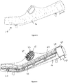
- the screen assembly 10 comprises a polyurethane deck 12 having a plurality of small slots formed therein.
- the deck 12 is mounted on a support frame comprises spaced apart side walls 14,16 joined by transversely extending bridging members extending beneath the deck (not shown).
- the support frame may be mounted on a base frame (not shown) via resilient mountings to allow the support frame to move with respect to the base frame.
- the support frame may be suspended from the base frame via suitable resilient mounts, such as springs.
- a vibration generating device is mounted between the side plates 14,16 of the support frame, extending transverse to the deck 12 of the screen assembly 10.
- the vibration generating device may comprise a pair of motor driven eccentrically loaded rotors (30,32, Figure 4 ) mounted within a support pipe 18 mounted between the side plates 14,16 for rotation about substantially parallel rotational axes extending transverse to the deck 12 or a single eccentrically driven rotor.
- the rotor or rotors may be adpated to generate a reciprocal or rotary motion to the deck 12. While the support pipe 18 housing the rotors is shown in drawings as being mounted above the deck 12, it is envisaged, that the or each rotor may be mounted beneath the deck 12, preferably within a tube mounted between the side plates.
- Rotation of the rotor or rotors causes a rotating out of balance force to be applied to the support frame, imparting a vibratory motion to the deck 12 and to the material carried thereon.
- Such vibratory motion causes the material placed on the deck 12 to be agitated, preventing blocking of the openings in the deck and causing material on the deck 12 to be conveyed towards one end of the screen assembly 10.
- the deck 12 is divided into a first or upstream portion comprising a grading section 20, upon which sand can be graded, undersize particles passing through the slots while oversized particles are retained on the deck, and a second or downstream portion comprising a dewatering section 22, upon which the sand, comprising the oversized particles, is dewatered.
- a feed box 34 is provided at an upper end of the deck 12 to feed water having sand entrained thereon onto the deck 12.
- the sand/water mix is passed into the feed box 34 via an inlet port 26 provided on a lower side of the feed box 34.
- the mixture passes out of the feed box 34 onto the deck via an elongate slot 38 provided in a side of the feed box 34.
- the grading section 20 of the deck is arranged to slope downwardly towards the dewatering section 22 at an angle to the horizontal suited to the grading operation, while the dewatering section 22 of the deck is arranged at a shallow upward angle sloping upwardly towards a discharge end of the dewatering section 22 to suite the dewatering operation.
- the grading section 20 of the deck may be arranged at an angle of about 25° to the horizontal.
- the dewatering section 22 of the deck slopes upwardly towards a discharge end thereof at an angle of between 0.5° and 5°.
- An upstanding weir 24 may be be provided at or adjacent a discharge end of the dewatering section 22 of the deck 12 to retaining sand upon the deck 12 during dewatering.
- the weir 24 may be omitted where the upward slope of the dewatering section 22 is sufficient to retain sand upon the deck during dewatering.
- the apertures or slots formed within the grading section 20 of the deck 22 may be between 0.2 mm and 2 mm wide while the apertures or slots in the dewatering section 22 of the deck 12 may be between 0.2 mm to 0.9 mm wide.
- the apertures in both the grading section 20 and the dewatering section 22 may be the same size.
- the length of the grading section 20 may be greater than the length of the dewatering section 22.
- Preferably the length of the grading section 20 is more than twice the length of the dewatering section 22.
- the side walls 14,16 of the frame are made up of a laminated assembly of approximately 4mm thick outer steel plates defining outer skins of the respective side wall and an approximately 20mm thick intermediate steel plate mounted therebetween.
- the outer skins and intermediate plate are clamped and connected together by nuts and bolts passing through the assembled plates.
- the intermediate plate may have a plurality of cut-outs formed therein defining hollow regions surrounded by elongate reinforcing webs and members.
- the shape and positions of the cut-outs can be selected to provide particular structural properties, such that the stiffness and strength of the side walls can be optimised while minimising the weight of the side walls 14,16 of the frame.
Claims (14)
- Ensemble formant crible (10) servant à classer et à égoutter du sable comportant un cadre sur lequel est monté un plateau (12) ayant une pluralité d'ouvertures dans celui-ci, le cadre étant monté sur une base et comportant un moyen générateur de vibrations (30, 32) servant à communiquer des vibrations au plateau, dans lequel le plateau (12) comporte une première partie (20) inclinée vers le bas depuis une première extrémité jusqu'à une deuxième extrémité servant à classer le sable se trouvant dessus et une deuxième partie (22) servant à égoutter le sable se trouvant dessus, dans lequel la première partie (20) du plateau (12) est inclinée vers le bas selon un premier angle par rapport à l'horizontale relativement à la direction normale d'avance de la matière sur le plateau et la deuxième partie (22) est inclinée vers le haut selon un deuxième angle par rapport à l'horizontale relativement à la direction normale d'avance de la matière sur le plateau (12), dans lequel, lors de l'utilisation, du sable peut être distribué sur le plateau (12) au niveau de la première extrémité de la première partie (20), ou de manière adjacente par rapport à celle-ci, les particules de sable de dimension inférieure passant au travers des ouvertures dans la première partie (20) du plateau alors que les particules de dimension supérieure sont transportées sur la première partie du plateau sous l'effet de la gravité avant de passer sur la deuxième partie (22) du plateau (12), ce par quoi les particules de dimension supérieure sont égouttées, caractérisé en ce que la longueur de la première partie (20) du plateau (12) est supérieure par rapport à la longueur de la deuxième partie (22) du plateau (12).
- Ensemble formant crible selon la revendication 1, dans lequel ledit deuxième angle est inférieur à 5°.
- Ensemble formant crible selon la revendication 1 ou la revendication 2, dans lequel ledit premier angle est supérieur à 5°.
- Ensemble formant crible selon la revendication 3, dans lequel le premier angle mesure approximativement 25°.
- Ensemble formant crible selon l'une quelconque des revendications précédentes, dans lequel les ouvertures dans la première partie (20) du plateau (12) sont plus grandes par rapport aux ouvertures dans la deuxième partie (22) du plateau (12).
- Ensemble formant crible selon l'une quelconque des revendications 1 à 4, dans lequel les ouvertures dans la première partie (20) du plateau sont sensiblement de la même dimension que les ouvertures dans la deuxième partie (22) du plateau.
- Ensemble formant crible selon l'une quelconque des revendications précédentes, dans lequel un déversoir surélevé (24) est mis en oeuvre au niveau d'une extrémité de décharge de la deuxième partie (22) du plateau (12), ou de manière adjacente par rapport à celle-ci, à des fins de retenue du sable sur la deuxième partie du plateau au cours de l'égouttage.
- Ensemble formant crible selon l'une quelconque des revendications précédentes, dans lequel le cadre comporte une paire de parois latérales sensiblement parallèles (14, 16) entre lesquelles le plateau (12) est monté.
- Ensemble formant crible selon la revendication 8, dans lequel les parois latérales (14, 16) sont interconnectées par une pluralité d'éléments formant pont s'étendant entre elles.
- Ensemble formant crible selon la revendication 8 ou la revendication 9, dans lequel ledit moyen générateur de vibrations comporte un ou plusieurs arbres tournants de manière excentrique (30, 32), lesdits un ou plusieurs arbres tournants de manière excentrique (30, 32) étant logés à l'intérieur d'un logement tubulaire allongé (18) s'étendant entre les parois latérales (14, 16) du cadre, ledit logement allongé définissant un composant de structure du cadre.
- Ensemble formant crible selon la revendication 10, dans lequel ledit logement tubulaire allongé (18) est situé au-dessus du plateau (12).
- Ensemble formant crible selon l'une quelconque des revendications 8 à 11, dans lequel chaque paroi latérale (14, 16) est formée à partir d'une pluralité de plaques parallèles comportant une plaque extérieure, et une plaque intérieure et au moins une plaque intermédiaire, la plaque intermédiaire ayant des découpes formées dans celle-ci pour définir une pluralité de nervures de renfort allongées.
- Ensemble formant crible selon la revendication 12, dans lequel ladite pluralité de plaques parallèles formant chaque paroi latérale (14, 16) du cadre sont serrées ensemble par le biais d'une pluralité d'attaches mécaniques.
- Ensemble formant crible selon l'une quelconque des revendications précédentes, dans lequel la longueur de la première partie (20) du plateau (12) mesure plus de deux fois la longueur de la deuxième partie (22) du plateau (12).
Applications Claiming Priority (2)
| Application Number | Priority Date | Filing Date | Title |
|---|---|---|---|
| GBGB1403245.2A GB201403245D0 (en) | 2014-02-25 | 2014-02-25 | Screen Assembly |
| GBGB1404507.4A GB201404507D0 (en) | 2014-02-25 | 2014-03-13 | Screen assembly |
Publications (2)
| Publication Number | Publication Date |
|---|---|
| EP2910313A1 EP2910313A1 (fr) | 2015-08-26 |
| EP2910313B1 true EP2910313B1 (fr) | 2019-01-09 |
Family
ID=50482724
Family Applications (1)
| Application Number | Title | Priority Date | Filing Date |
|---|---|---|---|
| EP15156120.6A Active EP2910313B1 (fr) | 2014-02-25 | 2015-02-23 | Ensemble d'écran |
Country Status (3)
| Country | Link |
|---|---|
| US (1) | US9409208B2 (fr) |
| EP (1) | EP2910313B1 (fr) |
| GB (3) | GB201403245D0 (fr) |
Families Citing this family (11)
| Publication number | Priority date | Publication date | Assignee | Title |
|---|---|---|---|---|
| GB201403245D0 (en) * | 2014-02-25 | 2014-04-09 | Cde Global Ltd | Screen Assembly |
| CN105149207B (zh) * | 2015-09-11 | 2018-01-09 | 凯迈(洛阳)机电有限公司 | 一种固液分离振动筛 |
| GB2550943A (en) | 2016-06-01 | 2017-12-06 | Cde Global Ltd | A Multi-deck screening assembly |
| CN106110734B (zh) * | 2016-07-24 | 2017-11-17 | 哈尔滨理工大学 | 具有振动功能的网格宽度连续调节滤网和连续调节方法 |
| CN107520114B (zh) * | 2017-08-07 | 2020-04-03 | 陕西航天泵阀科技集团有限公司 | 一种平动椭圆振动筛 |
| CN107759041A (zh) * | 2017-11-30 | 2018-03-06 | 福建帝凯农业综合开发有限公司 | 一种污水微生物处理系统 |
| GB2572332B (en) | 2018-03-26 | 2021-06-16 | Cde Global Ltd | Apparatus for grading and washing sand |
| CN111035983A (zh) * | 2020-01-06 | 2020-04-21 | 同济大学 | 一种用于生物硅藻土混合液中杂质去除的过滤装置 |
| GB2605811B (en) * | 2021-04-14 | 2023-05-10 | Cde Global Ltd | Dewatering screen |
| CN113857035A (zh) * | 2021-11-11 | 2021-12-31 | 怀化晶源建材有限公司 | 一种混凝土生产用除杂装置 |
| CN114682732B (zh) * | 2022-04-02 | 2024-01-26 | 福建省亿达精密铸造有限公司 | 铸造废砂刷洗回收机构 |
Citations (1)
| Publication number | Priority date | Publication date | Assignee | Title |
|---|---|---|---|---|
| CN203389407U (zh) * | 2013-06-05 | 2014-01-15 | 招远市创新矿山机械厂 | 一种振动脱水筛 |
Family Cites Families (11)
| Publication number | Priority date | Publication date | Assignee | Title |
|---|---|---|---|---|
| US2973865A (en) * | 1957-09-17 | 1961-03-07 | John F Cibula | Rocker screen vibrating machine with undulated screen cloth |
| US3452876A (en) | 1966-06-29 | 1969-07-01 | Bauer Bros Co | Dewatering equipment |
| US3835999A (en) | 1972-10-18 | 1974-09-17 | Bauer Bros Co | Screen units used for dewatering and classifying the contents of a liquid slurry |
| US3970549A (en) * | 1973-06-18 | 1976-07-20 | Linatex Corporation Of America | Screen assembly and dewatering technique |
| ZA743488B (en) * | 1973-06-18 | 1975-06-25 | Spargo Ltd R | Screen assembly and dewatering technique |
| DE2649376A1 (de) * | 1975-11-04 | 1977-05-12 | Terence Charles Adams | Verfahren zum herstellen eines siebes |
| US4519902A (en) * | 1982-04-30 | 1985-05-28 | Clinch River Corporation | Vibrating screening apparatus |
| US20050035033A1 (en) * | 1999-03-25 | 2005-02-17 | Adams Thomas C. | Methods for sealing screen assemblies on vibratory separators |
| US6889846B2 (en) * | 2002-03-15 | 2005-05-10 | Johnson Crushers International | Hybrid screen |
| CN202098880U (zh) * | 2011-05-30 | 2012-01-04 | 内蒙古电力勘测设计院 | 振动煤箅子 |
| GB201403245D0 (en) * | 2014-02-25 | 2014-04-09 | Cde Global Ltd | Screen Assembly |
-
2014
- 2014-02-25 GB GBGB1403245.2A patent/GB201403245D0/en not_active Ceased
- 2014-03-13 GB GBGB1404507.4A patent/GB201404507D0/en not_active Ceased
-
2015
- 2015-02-23 EP EP15156120.6A patent/EP2910313B1/fr active Active
- 2015-02-23 GB GB1502949.9A patent/GB2524651B/en active Active
- 2015-02-24 US US14/629,800 patent/US9409208B2/en active Active
Patent Citations (1)
| Publication number | Priority date | Publication date | Assignee | Title |
|---|---|---|---|---|
| CN203389407U (zh) * | 2013-06-05 | 2014-01-15 | 招远市创新矿山机械厂 | 一种振动脱水筛 |
Also Published As
| Publication number | Publication date |
|---|---|
| GB201404507D0 (en) | 2014-04-30 |
| US20150239013A1 (en) | 2015-08-27 |
| EP2910313A1 (fr) | 2015-08-26 |
| GB201403245D0 (en) | 2014-04-09 |
| GB2524651B (en) | 2016-12-14 |
| US9409208B2 (en) | 2016-08-09 |
| GB2524651A (en) | 2015-09-30 |
| GB201502949D0 (en) | 2015-04-08 |
Similar Documents
| Publication | Publication Date | Title |
|---|---|---|
| EP2910313B1 (fr) | Ensemble d'écran | |
| EP3463692B1 (fr) | Machine de criblage permettant de cribler des matériaux selon la taille | |
| EP2890505B1 (fr) | Tamis vibrant | |
| EP3061533A2 (fr) | Ensemble de criblage à plusieurs étages | |
| US9089877B2 (en) | Backing screen panels for vibrating screen separator | |
| AU2018200756B2 (en) | Method and apparatus for washing and grading aggregate | |
| EP3251759B1 (fr) | Ensemble de criblage à plusieurs étages | |
| AU4711297A (en) | Improved vibratory screening machine | |
| AU2018382236B2 (en) | A vibrating screen | |
| GB2318401A (en) | Vibratory screening machine | |
| US20230390804A1 (en) | Vibrating screen control arrangements | |
| KR101843016B1 (ko) | 골재의 선별 및 탈수장치 | |
| RU139262U1 (ru) | Вибрационный грохот | |
| GB2515489A (en) | Vibrating screen and support beam therefor | |
| RU2550607C2 (ru) | Вибрационный грохот | |
| IE20150194A1 (en) | Screen assembly |
Legal Events
| Date | Code | Title | Description |
|---|---|---|---|
| PUAI | Public reference made under article 153(3) epc to a published international application that has entered the european phase |
Free format text: ORIGINAL CODE: 0009012 |
|
| AK | Designated contracting states |
Kind code of ref document: A1 Designated state(s): AL AT BE BG CH CY CZ DE DK EE ES FI FR GB GR HR HU IE IS IT LI LT LU LV MC MK MT NL NO PL PT RO RS SE SI SK SM TR |
|
| AX | Request for extension of the european patent |
Extension state: BA ME |
|
| 17P | Request for examination filed |
Effective date: 20160218 |
|
| RBV | Designated contracting states (corrected) |
Designated state(s): AL AT BE BG CH CY CZ DE DK EE ES FI FR GB GR HR HU IE IS IT LI LT LU LV MC MK MT NL NO PL PT RO RS SE SI SK SM TR |
|
| RBV | Designated contracting states (corrected) |
Designated state(s): AL AT BE BG CH CY CZ DE DK EE ES FI FR GR HR HU IE IS IT LI LT LU LV MC MK MT NL NO PL PT RO RS SE SI SK SM TR |
|
| RIC1 | Information provided on ipc code assigned before grant |
Ipc: B01D 33/03 20060101ALI20180726BHEP Ipc: B07B 1/28 20060101AFI20180726BHEP Ipc: B07B 1/46 20060101ALI20180726BHEP |
|
| GRAP | Despatch of communication of intention to grant a patent |
Free format text: ORIGINAL CODE: EPIDOSNIGR1 |
|
| STAA | Information on the status of an ep patent application or granted ep patent |
Free format text: STATUS: GRANT OF PATENT IS INTENDED |
|
| INTG | Intention to grant announced |
Effective date: 20180905 |
|
| GRAS | Grant fee paid |
Free format text: ORIGINAL CODE: EPIDOSNIGR3 |
|
| GRAA | (expected) grant |
Free format text: ORIGINAL CODE: 0009210 |
|
| STAA | Information on the status of an ep patent application or granted ep patent |
Free format text: STATUS: THE PATENT HAS BEEN GRANTED |
|
| AK | Designated contracting states |
Kind code of ref document: B1 Designated state(s): AL AT BE BG CH CY CZ DE DK EE ES FI FR GR HR HU IE IS IT LI LT LU LV MC MK MT NL NO PL PT RO RS SE SI SK SM TR |
|
| REG | Reference to a national code |
Ref country code: CH Ref legal event code: EP Ref country code: AT Ref legal event code: REF Ref document number: 1086656 Country of ref document: AT Kind code of ref document: T Effective date: 20190115 |
|
| REG | Reference to a national code |
Ref country code: DE Ref legal event code: R096 Ref document number: 602015023038 Country of ref document: DE |
|
| REG | Reference to a national code |
Ref country code: IE Ref legal event code: FG4D |
|
| REG | Reference to a national code |
Ref country code: NL Ref legal event code: MP Effective date: 20190109 |
|
| REG | Reference to a national code |
Ref country code: LT Ref legal event code: MG4D |
|
| PG25 | Lapsed in a contracting state [announced via postgrant information from national office to epo] |
Ref country code: NL Free format text: LAPSE BECAUSE OF FAILURE TO SUBMIT A TRANSLATION OF THE DESCRIPTION OR TO PAY THE FEE WITHIN THE PRESCRIBED TIME-LIMIT Effective date: 20190109 |
|
| PG25 | Lapsed in a contracting state [announced via postgrant information from national office to epo] |
Ref country code: NO Free format text: LAPSE BECAUSE OF FAILURE TO SUBMIT A TRANSLATION OF THE DESCRIPTION OR TO PAY THE FEE WITHIN THE PRESCRIBED TIME-LIMIT Effective date: 20190409 Ref country code: FI Free format text: LAPSE BECAUSE OF FAILURE TO SUBMIT A TRANSLATION OF THE DESCRIPTION OR TO PAY THE FEE WITHIN THE PRESCRIBED TIME-LIMIT Effective date: 20190109 Ref country code: LT Free format text: LAPSE BECAUSE OF FAILURE TO SUBMIT A TRANSLATION OF THE DESCRIPTION OR TO PAY THE FEE WITHIN THE PRESCRIBED TIME-LIMIT Effective date: 20190109 Ref country code: PT Free format text: LAPSE BECAUSE OF FAILURE TO SUBMIT A TRANSLATION OF THE DESCRIPTION OR TO PAY THE FEE WITHIN THE PRESCRIBED TIME-LIMIT Effective date: 20190509 Ref country code: ES Free format text: LAPSE BECAUSE OF FAILURE TO SUBMIT A TRANSLATION OF THE DESCRIPTION OR TO PAY THE FEE WITHIN THE PRESCRIBED TIME-LIMIT Effective date: 20190109 Ref country code: SE Free format text: LAPSE BECAUSE OF FAILURE TO SUBMIT A TRANSLATION OF THE DESCRIPTION OR TO PAY THE FEE WITHIN THE PRESCRIBED TIME-LIMIT Effective date: 20190109 Ref country code: PL Free format text: LAPSE BECAUSE OF FAILURE TO SUBMIT A TRANSLATION OF THE DESCRIPTION OR TO PAY THE FEE WITHIN THE PRESCRIBED TIME-LIMIT Effective date: 20190109 |
|
| PG25 | Lapsed in a contracting state [announced via postgrant information from national office to epo] |
Ref country code: LV Free format text: LAPSE BECAUSE OF FAILURE TO SUBMIT A TRANSLATION OF THE DESCRIPTION OR TO PAY THE FEE WITHIN THE PRESCRIBED TIME-LIMIT Effective date: 20190109 Ref country code: RS Free format text: LAPSE BECAUSE OF FAILURE TO SUBMIT A TRANSLATION OF THE DESCRIPTION OR TO PAY THE FEE WITHIN THE PRESCRIBED TIME-LIMIT Effective date: 20190109 Ref country code: HR Free format text: LAPSE BECAUSE OF FAILURE TO SUBMIT A TRANSLATION OF THE DESCRIPTION OR TO PAY THE FEE WITHIN THE PRESCRIBED TIME-LIMIT Effective date: 20190109 Ref country code: IS Free format text: LAPSE BECAUSE OF FAILURE TO SUBMIT A TRANSLATION OF THE DESCRIPTION OR TO PAY THE FEE WITHIN THE PRESCRIBED TIME-LIMIT Effective date: 20190509 Ref country code: BG Free format text: LAPSE BECAUSE OF FAILURE TO SUBMIT A TRANSLATION OF THE DESCRIPTION OR TO PAY THE FEE WITHIN THE PRESCRIBED TIME-LIMIT Effective date: 20190409 Ref country code: GR Free format text: LAPSE BECAUSE OF FAILURE TO SUBMIT A TRANSLATION OF THE DESCRIPTION OR TO PAY THE FEE WITHIN THE PRESCRIBED TIME-LIMIT Effective date: 20190410 |
|
| REG | Reference to a national code |
Ref country code: CH Ref legal event code: PL |
|
| REG | Reference to a national code |
Ref country code: DE Ref legal event code: R097 Ref document number: 602015023038 Country of ref document: DE |
|
| PG25 | Lapsed in a contracting state [announced via postgrant information from national office to epo] |
Ref country code: DK Free format text: LAPSE BECAUSE OF FAILURE TO SUBMIT A TRANSLATION OF THE DESCRIPTION OR TO PAY THE FEE WITHIN THE PRESCRIBED TIME-LIMIT Effective date: 20190109 Ref country code: EE Free format text: LAPSE BECAUSE OF FAILURE TO SUBMIT A TRANSLATION OF THE DESCRIPTION OR TO PAY THE FEE WITHIN THE PRESCRIBED TIME-LIMIT Effective date: 20190109 Ref country code: CZ Free format text: LAPSE BECAUSE OF FAILURE TO SUBMIT A TRANSLATION OF THE DESCRIPTION OR TO PAY THE FEE WITHIN THE PRESCRIBED TIME-LIMIT Effective date: 20190109 Ref country code: IT Free format text: LAPSE BECAUSE OF FAILURE TO SUBMIT A TRANSLATION OF THE DESCRIPTION OR TO PAY THE FEE WITHIN THE PRESCRIBED TIME-LIMIT Effective date: 20190109 Ref country code: RO Free format text: LAPSE BECAUSE OF FAILURE TO SUBMIT A TRANSLATION OF THE DESCRIPTION OR TO PAY THE FEE WITHIN THE PRESCRIBED TIME-LIMIT Effective date: 20190109 Ref country code: SK Free format text: LAPSE BECAUSE OF FAILURE TO SUBMIT A TRANSLATION OF THE DESCRIPTION OR TO PAY THE FEE WITHIN THE PRESCRIBED TIME-LIMIT Effective date: 20190109 Ref country code: AL Free format text: LAPSE BECAUSE OF FAILURE TO SUBMIT A TRANSLATION OF THE DESCRIPTION OR TO PAY THE FEE WITHIN THE PRESCRIBED TIME-LIMIT Effective date: 20190109 Ref country code: MC Free format text: LAPSE BECAUSE OF FAILURE TO SUBMIT A TRANSLATION OF THE DESCRIPTION OR TO PAY THE FEE WITHIN THE PRESCRIBED TIME-LIMIT Effective date: 20190109 Ref country code: LU Free format text: LAPSE BECAUSE OF NON-PAYMENT OF DUE FEES Effective date: 20190223 |
|
| PLBE | No opposition filed within time limit |
Free format text: ORIGINAL CODE: 0009261 |
|
| STAA | Information on the status of an ep patent application or granted ep patent |
Free format text: STATUS: NO OPPOSITION FILED WITHIN TIME LIMIT |
|
| REG | Reference to a national code |
Ref country code: BE Ref legal event code: MM Effective date: 20190228 |
|
| PG25 | Lapsed in a contracting state [announced via postgrant information from national office to epo] |
Ref country code: SM Free format text: LAPSE BECAUSE OF FAILURE TO SUBMIT A TRANSLATION OF THE DESCRIPTION OR TO PAY THE FEE WITHIN THE PRESCRIBED TIME-LIMIT Effective date: 20190109 |
|
| 26N | No opposition filed |
Effective date: 20191010 |
|
| PG25 | Lapsed in a contracting state [announced via postgrant information from national office to epo] |
Ref country code: CH Free format text: LAPSE BECAUSE OF NON-PAYMENT OF DUE FEES Effective date: 20190228 Ref country code: LI Free format text: LAPSE BECAUSE OF NON-PAYMENT OF DUE FEES Effective date: 20190228 |
|
| PG25 | Lapsed in a contracting state [announced via postgrant information from national office to epo] |
Ref country code: SI Free format text: LAPSE BECAUSE OF FAILURE TO SUBMIT A TRANSLATION OF THE DESCRIPTION OR TO PAY THE FEE WITHIN THE PRESCRIBED TIME-LIMIT Effective date: 20190109 Ref country code: BE Free format text: LAPSE BECAUSE OF NON-PAYMENT OF DUE FEES Effective date: 20190228 |
|
| PG25 | Lapsed in a contracting state [announced via postgrant information from national office to epo] |
Ref country code: TR Free format text: LAPSE BECAUSE OF FAILURE TO SUBMIT A TRANSLATION OF THE DESCRIPTION OR TO PAY THE FEE WITHIN THE PRESCRIBED TIME-LIMIT Effective date: 20190109 |
|
| PG25 | Lapsed in a contracting state [announced via postgrant information from national office to epo] |
Ref country code: MT Free format text: LAPSE BECAUSE OF NON-PAYMENT OF DUE FEES Effective date: 20190223 |
|
| PG25 | Lapsed in a contracting state [announced via postgrant information from national office to epo] |
Ref country code: CY Free format text: LAPSE BECAUSE OF FAILURE TO SUBMIT A TRANSLATION OF THE DESCRIPTION OR TO PAY THE FEE WITHIN THE PRESCRIBED TIME-LIMIT Effective date: 20190109 |
|
| PG25 | Lapsed in a contracting state [announced via postgrant information from national office to epo] |
Ref country code: HU Free format text: LAPSE BECAUSE OF FAILURE TO SUBMIT A TRANSLATION OF THE DESCRIPTION OR TO PAY THE FEE WITHIN THE PRESCRIBED TIME-LIMIT; INVALID AB INITIO Effective date: 20150223 |
|
| REG | Reference to a national code |
Ref country code: AT Ref legal event code: UEP Ref document number: 1086656 Country of ref document: AT Kind code of ref document: T Effective date: 20190109 |
|
| PG25 | Lapsed in a contracting state [announced via postgrant information from national office to epo] |
Ref country code: MK Free format text: LAPSE BECAUSE OF FAILURE TO SUBMIT A TRANSLATION OF THE DESCRIPTION OR TO PAY THE FEE WITHIN THE PRESCRIBED TIME-LIMIT Effective date: 20190109 |
|
| PGFP | Annual fee paid to national office [announced via postgrant information from national office to epo] |
Ref country code: IE Payment date: 20230109 Year of fee payment: 9 Ref country code: FR Payment date: 20230221 Year of fee payment: 9 Ref country code: AT Payment date: 20230217 Year of fee payment: 9 |
|
| PGFP | Annual fee paid to national office [announced via postgrant information from national office to epo] |
Ref country code: DE Payment date: 20230216 Year of fee payment: 9 |
|
| P01 | Opt-out of the competence of the unified patent court (upc) registered |
Effective date: 20230530 |
|
| PGFP | Annual fee paid to national office [announced via postgrant information from national office to epo] |
Ref country code: IE Payment date: 20240124 Year of fee payment: 10 |