EP2910309A1 - Magnetic sorting apparatus, magnetic sorting method, and method for manufacturing iron source - Google Patents
Magnetic sorting apparatus, magnetic sorting method, and method for manufacturing iron source Download PDFInfo
- Publication number
- EP2910309A1 EP2910309A1 EP13846992.9A EP13846992A EP2910309A1 EP 2910309 A1 EP2910309 A1 EP 2910309A1 EP 13846992 A EP13846992 A EP 13846992A EP 2910309 A1 EP2910309 A1 EP 2910309A1
- Authority
- EP
- European Patent Office
- Prior art keywords
- conveyer
- belt
- magnetic
- powder
- granular material
- Prior art date
- Legal status (The legal status is an assumption and is not a legal conclusion. Google has not performed a legal analysis and makes no representation as to the accuracy of the status listed.)
- Granted
Links
Images






Classifications
-
- B—PERFORMING OPERATIONS; TRANSPORTING
- B03—SEPARATION OF SOLID MATERIALS USING LIQUIDS OR USING PNEUMATIC TABLES OR JIGS; MAGNETIC OR ELECTROSTATIC SEPARATION OF SOLID MATERIALS FROM SOLID MATERIALS OR FLUIDS; SEPARATION BY HIGH-VOLTAGE ELECTRIC FIELDS
- B03C—MAGNETIC OR ELECTROSTATIC SEPARATION OF SOLID MATERIALS FROM SOLID MATERIALS OR FLUIDS; SEPARATION BY HIGH-VOLTAGE ELECTRIC FIELDS
- B03C1/00—Magnetic separation
- B03C1/02—Magnetic separation acting directly on the substance being separated
- B03C1/16—Magnetic separation acting directly on the substance being separated with material carriers in the form of belts
- B03C1/18—Magnetic separation acting directly on the substance being separated with material carriers in the form of belts with magnets moving during operation
-
- B—PERFORMING OPERATIONS; TRANSPORTING
- B03—SEPARATION OF SOLID MATERIALS USING LIQUIDS OR USING PNEUMATIC TABLES OR JIGS; MAGNETIC OR ELECTROSTATIC SEPARATION OF SOLID MATERIALS FROM SOLID MATERIALS OR FLUIDS; SEPARATION BY HIGH-VOLTAGE ELECTRIC FIELDS
- B03C—MAGNETIC OR ELECTROSTATIC SEPARATION OF SOLID MATERIALS FROM SOLID MATERIALS OR FLUIDS; SEPARATION BY HIGH-VOLTAGE ELECTRIC FIELDS
- B03C1/00—Magnetic separation
- B03C1/02—Magnetic separation acting directly on the substance being separated
- B03C1/025—High gradient magnetic separators
- B03C1/031—Component parts; Auxiliary operations
- B03C1/033—Component parts; Auxiliary operations characterised by the magnetic circuit
- B03C1/0332—Component parts; Auxiliary operations characterised by the magnetic circuit using permanent magnets
-
- B—PERFORMING OPERATIONS; TRANSPORTING
- B03—SEPARATION OF SOLID MATERIALS USING LIQUIDS OR USING PNEUMATIC TABLES OR JIGS; MAGNETIC OR ELECTROSTATIC SEPARATION OF SOLID MATERIALS FROM SOLID MATERIALS OR FLUIDS; SEPARATION BY HIGH-VOLTAGE ELECTRIC FIELDS
- B03C—MAGNETIC OR ELECTROSTATIC SEPARATION OF SOLID MATERIALS FROM SOLID MATERIALS OR FLUIDS; SEPARATION BY HIGH-VOLTAGE ELECTRIC FIELDS
- B03C2201/00—Details of magnetic or electrostatic separation
- B03C2201/20—Magnetic separation of bulk or dry particles in mixtures
-
- B—PERFORMING OPERATIONS; TRANSPORTING
- B03—SEPARATION OF SOLID MATERIALS USING LIQUIDS OR USING PNEUMATIC TABLES OR JIGS; MAGNETIC OR ELECTROSTATIC SEPARATION OF SOLID MATERIALS FROM SOLID MATERIALS OR FLUIDS; SEPARATION BY HIGH-VOLTAGE ELECTRIC FIELDS
- B03C—MAGNETIC OR ELECTROSTATIC SEPARATION OF SOLID MATERIALS FROM SOLID MATERIALS OR FLUIDS; SEPARATION BY HIGH-VOLTAGE ELECTRIC FIELDS
- B03C2201/00—Details of magnetic or electrostatic separation
- B03C2201/22—Details of magnetic or electrostatic separation characterised by the magnetic field, e.g. its shape or generation
Definitions
- the present invention relates to a technology to magnetically separate (separate) ferromagnetic particles from a powder and granular material containing the ferromagnetic particles and relates to, for example, a magnetic separator and a magnetic separation method, which are suitable for separating an iron content from a slag obtained as a by-product of an ironmaking process, and a method for manufacturing an iron source.
- a slag (steelmaking slag) is generated as a by-product in a molten pig iron pretreatment or a converter decarbonization step.
- the slag is generated on the basis of reaction of a calcium based additive added to remove impurities and unnecessary elements in the molten pig iron and a molten steel (sometimes iron and steel are collectively called iron) with these impurities and unnecessary elements. Besides the removed impurities and unnecessary elements, a high proportion of iron content is also contained in the slag.
- the iron content has been separated and recovered.
- the iron content is separated and recovered by the following steps. Initially, the slag is sieved to remove large (several hundreds of millimeters) blocks included in the slag. In small blocks passed through a sieve, an iron content and a slag content adhere to each other. Therefore, rough crushing into the size of several tens of micrometers to several tens of millimeters is performed with a hammer crusher, a rod mill, or the like to facilitate liberation (separation of the iron content from the slag content). Thereafter, the iron content is separated with a magnetic separator.
- examples of apparatuses used as the magnetic separator include suspended electro magnets, magnetic drum separators, and magnetic pulleys.
- a slag is heated and is cooled for an appropriate time, followed by crushing. It is possible to separate only the adhering slag content without crushing iron blocks or micronize the slag into several tens of micrometers depending on the cooling time.
- the particle diameter of the slag is reduced by repeating mechanical crushing.
- the diameter may be reduced by a heat treatment.
- a magnetic separator shown in Fig. 8 has been previously used (for example, NPL 1).
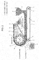
- This apparatus is a magnetic pulley type (belt conveyer style) magnetic separator, where a powder and granular material (a) containing ferromagnetic particles is supplied from a supply device 23 onto a conveyer belt 20, and ferromagnetic particles and non-magnetic particles are separated when the powder and granular material a is discharged from a conveyer end edge portion 27.
- magnets 22 are disposed in part of the circumferential direction.
- the magnets 22 are disposed in such a way that magnetic poles adjacent in the circumferential direction of the belt guide roll 21 are different from each other.
- the magnets 22 are stationary magnets disposed independently of the belt guide roll 21.
- the magnetic forces of the magnets 22 inside the belt guide roll 21 act on the powder and granular material a on the conveyer belt 20 in the conveyer end edge portion 27, non-magnetic particles not attracted by the magnets 22 fall first so as to be recovered by a magnetically not-attracted material recovery portion 24y, and the ferromagnetic particles attracted by the magnets 22 pass through a partition plate 25 disposed below the belt guide roll 21 and fall at positions at which the magnetic force is weakened, so as to be recovered by a magnetically attracted material recovery portion 24x.
- the micronized powder and granular material a is in the state in which ferromagnetic particles enclose non-magnetic particles, and the ferromagnetic particles and the non-magnetic particles are attracted by the magnet 22 at the same time, so that the ferromagnetic particles and the non-magnetic particles are not separated from each other easily. This becomes considerable as the particle diameter of the powder and granular material a decreases.
- PTL 1 proposes a method in which foreign matters are separated without over-crushing the slag by undergoing a plurality of specific steps.
- the separation flow becomes complicated and the treatment cost increases.
- a wet process is commonly applied in order to avoid agglomeration, but there is a problem that a waste fluid disposal cost increases considerably.
- the present inventors obtained the following findings on the magnetic separation.
- Fig. 1 (A) to (D) schematically show the above-described actions.
- the magnetic poles of the magnet of the portion facing the powder and granular material are referred to as the north pole and the south pole.
- the magnet is moved from the state in which the ferromagnetic particles on the conveyer belt 2 are attracted by the north pole, as shown in Fig. 1 (A) , to the state in which a space portion between the north pole and the south pole faces the powder and granular material, as shown in Fig. 1 (B) , the magnitude of the attractive force acted on the ferromagnetic particles is changed because of the strength of the magnetic field.
- the ferromagnetic particles are attracted in the direction of arrows because of the change in the magnetic pole from the north pole to the south pole and are moved to the magnet side while being rolled. Thereafter, as shown in Fig. 1 (C) , the ferromagnetic particles are attracted by the south pole and are further moved to the magnet side. The above-described actions are repeated and, thereby, the ferromagnetic particles originally distributed in the whole powder and granular material layer are gathered to the side nearest to the magnet in the powder and granular material layer, as shown in Fig. 1 (D) .
- This phenomenon always occurs if at least one of the magnet and the powder and granular material a is moved, and the same goes for the case where the magnet is fixed and only the powder and granular material a is moved.
- Fig. 1 (A) to (D) show the case where the magnets are moved from the right side to the left side in the drawing, although the same goes for the case where the magnets are moved from the left side to the right side in the drawing, in theory.
- the present inventors found that the ferromagnetic particles were able to be magnetically separated efficiently by applying the above-described mechanism to a belt conveyer style magnetic separator, disposing magnets inside the belt guide roll on the conveyer end edge side in such a way that adjacent magnetic poles in the portion facing the powder and granular material were arranged to become different from each other along the circumferential direction of the belt guide roll and, in addition, in such a way that adjacent magnetic poles in the portion facing the powder and granular material were arranged to become the same in the width direction of the belt guide roll, and moving the powder and granular material in the magnetic field formed by these magnets.
- the effect is further enhanced by rotating the magnets and, thereby, changing the strength and the direction of the magnetic field acted on the ferromagnetic particles at a high speed.
- the present invention has been made on the basis of the above-described findings and the gist is as described below.
- ferromagnetic particles are separated from a powder and granular material containing the ferromagnetic particles in one separation step efficiently and magnetic separation can be performed at a low cost without the need for complicated steps, waste fluid disposal, and the like even in the case where a large amount of powder and granular material containing ferromagnetic particles is treated and in the case where the layer of a supplied powder and granular material is thick.
- a magnetic separator and a magnetic separation method according to the present invention are to separate ferromagnetic particles from a powder and granular material containing the ferromagnetic particles by a magnetic force.
- the magnetic separator according to the present invention includes a belt to carry the powder and granular material, a rotatable belt guide roll having an outer circumference partly wound with the above-described or an other belt, and a magnetic field application device provided with a plurality of magnets disposed inside the guide roll.
- the magnets are arranged in such a way that the magnetic poles of the portion facing the powder and granular material come into alternate sequence along the circumferential direction of the belt guide roll and, in addition, are arranged in such a way that the magnetic poles of the portion facing the powder and granular material become the same in the width direction of the belt guide roll.
- the magnetic poles are the same in the width direction, a uniform magnetic field is formed and the force acted on the ferromagnetic particles also becomes uniform, and the separation efficiency of the ferromagnetic particles can be enhanced.
- the magnetic separation method according to the present invention separates ferromagnetic particles from a powder and granular material containing the ferromagnetic particles by using the magnetic separator having the above-described configuration.
- the magnetic field change frequency F (Hz), which is defined by the following formula (1) and which indicates changes in the strength of the magnetic field acted on the powder and granular material from the magnetic field application device, is specified to be 170 Hz or more.
- the magnetic field change frequency F is more preferably 200 Hz or more.
- F x ⁇ P / 60
- High-speed changes in the strength and the direction of the magnetic field acted on the powder and granular material are allowed to occur by specifying the magnetic field change frequency F (Hz) of the magnetic field application device to be 170 Hz or more, and preferably 200 Hz or more, so that it becomes possible to separate the ferromagnetic particles contained in the powder and granular material accurately.
- F magnetic field change frequency
- Fig. 2 is an explanatory diagram showing a magnetic separator according to a first embodiment of the present invention and an embodiment of a magnetic separation method by using this apparatus.
- the apparatus includes a first belt conveyer A to carry a powder and granular material (a) and a second belt conveyer B which is located above the belt conveyer A and which attracts and separates ferromagnetic particles, by magnets, from the powder and granular material a carried with the belt conveyer A.
- reference numeral 1 denotes a conveyer belt
- reference numeral 8 denotes a belt guide roll on the conveyer start edge portion 14 side
- reference numeral 9 denotes a belt guide roll on the conveyer end edge portion 10 side.
- the conveyer belt 1 is disposed between the belt guide rolls 8 and 9 and, thereby, the belt conveyer A is constructed.
- reference numeral 2 denotes a conveyer belt
- reference numeral 3 denotes a belt guide roll at the conveyer start edge portion 11 side
- reference numeral 13 denotes a belt guide roll at the conveyer end edge portion 12 side.
- the conveyer belt 2 is disposed between the belt guide rolls 3 and 13 and, thereby, the belt conveyer B is constructed.
- the belt guide roll 3 is configured to have a diameter larger than the diameter of the belt guide roll 13 and the axis of rotation of the belt guide roll 13 is located upper than the axis of rotation of the belt guide roll 3, so that the upper surface of the conveyer belt 2 (an upper belt portion between the belt guide rolls 3 and 13) is almost horizontal. However, the upper surface of the conveyer belt 2 may come down toward the belt guide roll 13.
- a supply device 6 to supply the powder and granular material a containing the ferromagnetic particles is disposed above the conveyer belt 1 and at the position near to the conveyer start edge portion 14 of the belt conveyer A.
- the ferromagnetic particles attracted and held on the belt conveyer B side are carried with the belt conveyer B and, thereafter, discharged from the conveyer end edge portion 12. Therefore, a magnetically attracted material recovery portion 7x is disposed below the conveyer end edge portion 12 of the belt conveyer B. Also, non-magnetic particles fall below the conveyer start edge portion 11 of the belt conveyer B, so that a magnetically not-attracted material recovery portion 7y is disposed at that position.
- the conveyer start edge portion 11 of the belt conveyer B is closely located above the conveyer end edge portion 10 of the belt conveyer A.
- the belt guide rolls 8 and 9 of the belt conveyer A and the belt guide rolls 3 and 13 of the belt conveyer B are rotated in the directions reverse to each other and the conveyer belts 1 and 2 are moved in the same direction in the conveyer end edge portion 10 of the belt conveyer A and the conveyer start edge portion 11 of the belt conveyer B.
- any one of the belt guide rolls 3 and 13 may be a driven roll driven by a drive device, e.g., a motor.
- the belt guide roll 13 is a driven roll and the belt guide roll 3 is a non-driven roll.
- the belt guide roll 3 is formed from a sleeve body with a hollow inside and is rotatably supported.
- a magnet roll 4r serving as a magnetic field application device provided with a plurality of magnets 5 is disposed inside the belt guide roll 3.
- the magnet roll 4r is configured to be be able to rotate independently of the belt guide roll 3.
- the magnet roll 4r is provided with the plurality of magnets 5 at predetermined intervals in the circumferential direction and the width direction of the belt guide roll 3.
- the plurality of magnets 5 are arranged with magnetic poles aligned in such a way that alternating north poles and south poles adjoin over 360°C in the roll circumference direction of the magnet roll 4r.
- the plurality of magnets 5 are arranged in such a way that the same magnetic poles are aligned in the width direction of the magnet roll 4r.
- the number of magnets 5 arranged in the roll circumferential direction, the interval of the magnets 5, and the like are not specifically limited. Higher speed of changes in the strength and the direction of the magnetic field are obtained by increasing the number of the magnets 5 or reducing the interval of the magnets 5. Put another way, high-speed changes in the magnetic field are obtained even when the rotational speed of the magnet roll 4r is low.
- the strength of the magnetic field due to the magnets 5 is not specifically limited.
- the magnets 5 are selected in such a way that about 0.01 to 0.5 T is ensured in the conveyer belt portion in contact with the belt guide roll 3 in accordance with an object. If the magnetic field is too weak, the effect of the magnet roll 4r is not obtained sufficiently. On the other hand, if the magnetic field is too strong, the attractive force acted on the ferromagnetic particles is too strong and, on the contrary, separation of the ferromagnetic particles may be hindered.
- the magnetic field is switched in the manner of strong ⁇ weak ⁇ strong ⁇ weak ⁇ ⁇ and the effect on the ferromagnetic particles in the powder and granular material layer is repeated in the manner of gathering ⁇ dispersion ⁇ gathering ⁇ dispersion ⁇ ⁇ because of the plurality of magnets 5 arranged at the predetermined interval and the space portions between adjacent magnets 5.
- the width of space portions between magnets 5 adjacent in the circumferential direction is not specifically limited, although about 1 to 50 mm is appropriate to obtain the above-described effects.
- Fig. 3 is a perspective view showing the structure of the belt guide roll of the magnetic separator according to the first embodiment shown in Fig. 2 .
- the magnet roll 4r provided with the plurality of magnets is disposed inside the belt guide roll 3.
- Reference numeral 40 denotes a roll shaft of the magnet roll 4r.
- Roll shafts 30 at both ends of the belt guide roll 3 are allowed to cover the roll shaft 40 of the magnet roll 4r disposed inside the belt guide roll 3 and are fitted to the roll shaft 40 with a bearing 15 (metal bearing, roller bearing, or the like) therebetween.
- the belt guide roll 3 and the magnet roll 4r can be rotated independently of each other and the roll shaft 30 and the roll shaft 40 can take various forms.
- the magnet roll 4r is a roll rotated by a device, e.g., a motor, and the rotational direction thereof may be the same as or reverse to the direction of the belt guide roll 3. In general, the rotation is in the direction reverse to the direction of the belt guide roll 3. In this regard, the magnet roll 4r is rotated at a speed higher than the speed of the belt guide roll 3.
- a device e.g., a motor
- the magnetic field change frequency F (Hz), which is defined by the following formula (1), of the magnet roll 4r is specified to be preferably 170 Hz or more.
- the magnetic field change frequency is more preferably 200 Hz or more.
- the upper limit of the magnetic field change frequency is about 1,000 Hz because there is a mechanical upper limit to the number of revolutions per minute of the magnet roll 4r and the effect of changes in the magnetic field may be saturated even when the frequency is increased.
- the size of the magnet 5 is not specifically limited insofar as the size is suitable for arranging the predetermined number of magnets 5.
- the magnetic poles of one magnet 5 are arranged in such a way that the magnetic pole on the inner circumferential side of the magnet roll 4r is different from the magnetic pole on the outer circumferential side.
- the magnets 5 may be disposed in such a way that the different magnetic poles of one magnet 5 are arranged in the circumferential direction of the magnet roll 4r.
- the north pole and the south pole are disposed alternately, so that the ferromagnetic particles can be separated efficiently.
- the north pole and the south pole may be disposed with a space portion therebetween.
- the north poles may be disposed with a space portion therebetween and the south poles may be disposed with a space portion therebetween.
- the space portions between the magnets 5 may be filled with a resin or the like, and a cover may be attached to the outer circumference of the magnet roll 4r.
- the rotational direction of the magnet roll 4r may be either (i) the direction reverse to the movement direction of the conveyer belt 2 (the rotational direction of the belt guide roll 3) or (ii) the same direction as the movement direction of the conveyer belt 2 (the rotational direction of the belt guide roll 3).
- a carrying force is exerted on the ferromagnetic particles to move in the direction reverse to the rotational direction of the magnet roll 4r because of the action of the magnetic field of the rotating magnet roll 4r.
- the carrying force exerted on the ferromagnetic particles by the magnetic field and the frictional force between the conveyer belt 2 and the ferromagnetic particles become the same direction.
- the ferromagnetic particle separation efficiency is slightly lower than that in the case of the item (ii), but the ferromagnetic particles do not stay on the conveyer belt 2 and, therefore, there is an advantage that the particles can be carried smoothly.
- the belt feed speeds of the conveyer belts 1 and 2 of the belt conveyers A and B may be specified to be speeds required for the treatment process.
- the rotational speed of the magnet roll 4r is determined in such a way that the speed of changes in the magnetic field becomes sufficiently high relative to this belt feed speed.
- the rotational speed of the magnet roll 4r be set in such a way as to satisfy the above-described condition represented by the formula (1).
- a sufficient thickness of powder and granular material a containing the ferromagnetic particles is supplied from the supply device 6 to the moving conveyer belt 1 of the belt conveyer A, while the belt conveyers A and B are operated.
- This powder and granular material a is carried to the conveyer end edge portion 10.
- the upper surface of the powder and granular material a carried with the conveyer belt 1 is brought into contact with the lower surface of the conveyer start edge portion 11 of the belt conveyer B in the vicinity of the conveyer end edge portion 10, and the powder and granular material a slips between the conveyer end edge portion 10 of the belt conveyer A and the conveyer start edge portion 11 of the belt conveyer B.
- the magnetic field of the magnetic field application device 4 of the belt conveyer B is exerted on the powder and granular material a.
- the ferromagnetic particles in the form of enclosing non-magnetic particles in the powder and granular material a are attached to the lower surface side of the belt conveyer B because of the magnetic force of the magnet roll 4r serving as the magnetic field application device 4 and are carried with the conveyer belt 2.
- the ferromagnetic particles in the powder and granular material a undergo action of the magnetic field of the magnets 5 included in the magnet roll 4r and the strength of the magnetic field is switched in the manner of strong ⁇ weak ⁇ strong ⁇ weak ⁇ ⁇ instantaneously because of the rotation of the magnet roll 4r.
- the effect in the manner of gathering ⁇ dispersion ⁇ gathering ⁇ dispersion ⁇ ⁇ is repeated on the ferromagnetic particles in the powder and granular material layer.
- the magnetic field application device is formed from the magnet roll 4r which is rotated independently of the belt guide roll 3, as in the embodiment shown in Fig. 2 , the ferromagnetic particles can be efficiently magnetically separated even when the thickness of the powder and granular material a supplied to the conveyer belt 1 is sufficiently increased, as shown in Fig.
- the ferromagnetic particles can be magnetically separated from the powder and granular material a efficiently, even if the thickness of the powder and granular material a supplied to the conveyer belt 1 is large. That is, the ferromagnetic particles can be magnetically separated from the powder and granular material a efficiently and quickly.
- the magnet roll 4r is rotated and, thereby, 100 times or more in number of changes in the strength and the direction of the magnetic field are given easily while the powder and granular material a is carried along the belt guide roll 3 of the belt conveyer B.
- the behavior of the ferromagnetic particles in the magnetic field is changed depending on the powder and granular material a concerned, so that the number of revolutions per minute of the magnet roll 4r can be adjusted to obtain appropriate performance.
- the magnetic separator according to the present first embodiment can magnetically separate the ferromagnetic particles from the powder and granular material a efficiently. Therefore, in magnetic separation of the powder and granular material a by using this apparatus, as shown in Fig. 2 , it is desirable that the powder and granular material be supplied from the supply device 6 to the conveyer belt 1 of the belt conveyer A with a layer thickness larger than the diameter of the smallest particle contained in the powder and granular material a and, in addition, with a layer thickness which allows the magnetic force to act sufficiently. Specifically, the thickness of the powder and granular material may be 20 to 30 mm.
- the powder and granular material which is the object of magnetic separation by the apparatus according to the present first embodiment is not specifically limited.
- examples thereof include slag, e.g., ironmaking slag, and tailing ores.
- slag e.g., ironmaking slag
- tailing ores e.g., ironmaking slag
- application to the magnetic separation of slag is favorable.
- the ironmaking slag is micronized. If the micronization is insufficient, the recovery rate of the iron content is not improved. There are various steps in the ironmaking and steelmaking processes to generate the ironmaking slag, so that various types of slags are generated.
- the slag particle diameter after the micronization is determined depending on the slag. In many cases, micronization to several tens of micrometers to about 1 millimeter is required depending on the form of iron contained. The common method for micronization is crushing.
- Crushing with a jaw crusher or a hammer crusher is performed as rough crushing and, thereafter, crushing is performed by using a ball mill, a rod mill, a jet mill, a pin mill, an impact mill, or the like for the purpose of micronization.
- a method in which heating to about 1,000°C to 1,300°C is performed and, thereafter, cooling is performed gradually is also mentioned.
- the magnetic separator according to the present invention, where the object is the micronized slag.
- the iron content can be separated and recovered from the slag efficiently by the present invention.
- magnets 5 are disposed over the width direction of the belt guide roll 3 (magnet roll 4r) in such a way that the magnetic poles of the portion facing the powder and granular material a become the same.
- a uniform magnetic field is formed and a force acted on the ferromagnetic particles becomes uniform.
- the magnets 5 are arranged in such a way that the magnetic poles are different in the width direction, the magnetic field becomes nonuniform and portions, where ferromagnetic particles are not separated, result locally, so that the separation efficiency is reduced.
- the members around the rotating magnet roll are influenced by an eddy-current effect due to the changing magnetic field, and metal members, which are even non-magnetic materials, are heated by the eddy current. Consequently, the conveyer belt 2 and the belt guide roll 3 of the belt conveyer B according to the present embodiment are formed from nonmetal, e.g., resin or ceramics.
- the apparatus according to the present first embodiment separates the ferromagnetic particles by allowing the magnetic field of the magnet roll 4r disposed inside the belt guide roll 3 on the conveyer start edge portion 11 side of the belt conveyer B to act on the powder and granular material a (powder and granular material layer) carried with the belt conveyer A and attracting and moving the ferromagnetic particles in the powder and granular material a to the lower surface side of the belt conveyer B. Therefore, the distance between the conveyer end edge portion 10 of the belt conveyer A and the conveyer start edge portion 11 of the belt conveyer B may be a dimension at which the magnetic force of the magnet roll 4r acts on the ferromagnetic particles in the powder and granular material a sufficiently.
- Fig. 4 is a diagram showing a magnetic separator according to the modified example 1 of the the first embodiment of the present invention.
- the positional relationship between the belt conveyer A and the belt conveyer B is specified to be a form different from the form shown in Fig. 1 . That is, the conveyer start edge portion 11 of the belt conveyer B is closely located above the conveyer end edge portion 10 of the belt conveyer A, and the belt guide rolls 8 and 9 of the belt conveyer A and the belt guide rolls 3 and 13 of the belt conveyer B are rotated in the same direction. Meanwhile, the conveyer belts 1 and 2 are moved in the directions reverse to each other in the conveyer end edge portion 10 of the belt conveyer A and the conveyer start edge portion 11 of the belt conveyer B.
- the ferromagnetic particles can be separated.
- the configuration other than the positional relationship between the belt conveyers A and B is substantially the same as the configuration of the first embodiment shown in Figs. 2 and 3 and, therefore, the explanations thereof will not be provided.
- FIG. 5 is an explanatory diagram showing the modified example 2 of the magnetic separator according to the first embodiment of the present invention and a magnetic separation method by using this apparatus.
- the belt guide roll 3 is formed from a sleeve body with a hollow inside and is rotatably supported.
- a magnetic field application device 4 provided with a plurality of magnets 5, which are arranged at a predetermined interval along the roll circumferential direction, is disposed inside the belt guide roll 3.
- the magnetic field application device 4 in the modified example 2 is not rotated in contrast to the magnet roll 4r in the first embodiment.
- the magnets 5 of the magnetic field application device 4 are disposed independently of the belt guide roll 3 and are stationary magnets which are not rotated.
- the magnets 5 of the magnetic field application device 4 are arranged in such a way that the magnetic poles adjacent in the roll circumferential direction are different from each other and, in addition, are arranged in such a way that the magnetic poles adjacent in the roll width direction are the same.
- the range of disposition of the magnets 5 in the roll circumferential direction is the range of at least about 180° (one-half the circumference of the belt guide roll 3) which is from the lower edge portion of the belt guide roll 3 (the position facing the conveyer end edge portion 10 of the belt conveyer A) to the top position of the belt guide roll 3.
- the range of disposition of the magnets 5 can be reduced by disposing the magnets 5 in such a way that the magnets 5 are fixed and are not rotated, as in the example 2.
- the ferromagnetic particles in the powder and granular material a are attracted by the magnetic field application device 4 provided with stationary magnets 5, and the powder and granular material a (or part thereof) having the form, in which the ferromagnetic particles enclose non-magnetic particles, is attached to (held by) the lower surface side of the belt conveyer B and are carried with the conveyer belt 2.
- the effect is small as compared with the effect of the magnet roll 4r shown in Fig.
- the ferromagnetic particles in the powder and granular material a undergo action of the magnetic force of the magnets 5 included in the magnetic field application device 4 and the magnetic field is switched in the manner of strong ⁇ weak ⁇ strong ⁇ weak ⁇ ⁇ during carrying with the conveyer belt 2. Consequently, the manner of gathering ⁇ dispersion ⁇ gathering ⁇ dispersion ⁇ ⁇ is repeated with respect to the ferromagnetic particles in the powder and granular material a, so that the same quality of effect as with the first embodiment shown in Fig. 2 is obtained.
- the magnetic field does not change at a high speed in contrast to the magnet roll 4r shown in Fig. 2 and, therefore, the magnetic separability and the treatment speed are low as compared with those in the first embodiment shown in Fig. 2 .
- the magnetic separator according to the modified example 2 has operation advantages, such as, (i) in the adopted basic system, the magnetic field by the magnetic field application device 4 included in the second belt conveyer B is acted on the powder and granular material a, which is discharged from the first belt conveyer A, from above to attract the ferromagnetic material contained in the powder and granular material a and move to the belt conveyer B side, so that enclosure and entanglement of the non-magnetic particles by the ferromagnetic particles can be reduced as compared with those of the apparatus in the related conventional art and, in addition, (ii) entanglement and enclosure of the non-magnetic particles by the ferromagnetic particles are resolved on the basis of changes in the magnetic field by the magnetic field application device 4.
- Fig. 6 is a perspective view showing the structure of a belt guide roll of a modified example 3 of the magnetic separator according to the first embodiment shown in Fig. 2 .
- magnets 5 are included in the magnet roll 4r, where a plurality of magnets 5 are disposed in the circumferential direction of the belt guide roll 3 (magnet roll 4r) and only one magnet 5 is disposed in the width direction of the belt guide roll 3 (magnet roll 4r).
- the magnets 5 are arranged in such a way that the magnetic poles facing the powder and granular material a come into alternate sequence along the circumferential direction.
- the magnets 5 may have the above-described configuration.
- Fig. 7 is an explanatory diagram showing an embodiment of a magnetic separator according to a second embodiment of the present invention and a magnetic separation method by using this apparatus.
- the magnetic separator according to the present second embodiment is a belt conveyer style magnetic separator as with the first embodiment.
- the magnetic separator according to the second embodiment supplies a powder and granular material (a) containing ferromagnetic particles from a supply device to a conveyer belt 201 and attracts and separates the ferromagnetic particles, by a magnetic force, from non-magnetic particles when the powder and granular material a is discharged from a conveyer end edge portion 2010.
- reference numeral 201 denotes a conveyer belt
- reference numeral 202 denotes a belt guide roll on the conveyer end edge portion 2010 side
- reference numeral 208 denotes a belt guide roll on the conveyer start edge portion 2011 side.
- the conveyer belt 201 is disposed between the belt guide rolls 202 and 208 and, thereby, the belt conveyer is formed.
- the belt guide roll 208 is driven by a drive device, e.g., a motor, and thereby, the conveyer belt 201 is rotated in the belt conveyer.
- the belt guide roll 202 is a non-driven roll and is formed from a sleeve body with a hollow inside.
- a magnet roll 203 is disposed inside the belt guide roll 202.
- the configuration of the magnet roll 203 is substantially the same as the configuration shown in Fig. 3 .
- the magnet roll 203 is provided with a plurality of magnets 205 arranged in the circumference direction and the width direction thereof at predetermined intervals and, in addition, the magnetic poles of the magnets 205 adjacent in the roll circumferential direction are different magnetic poles (north pole, south pole). That is, magnets 205 are arranged in such a way that the north poles and the south poles are arranged alternately in the roll circumference direction.
- the plurality of magnets 205 are arranged in such a way that the same magnetic poles are aligned in the roll width direction.
- the magnet roll 203 is a roll rotated by a motor or the like and is rotated in the direction reverse to the direction of the belt guide roll 202. Also, as described later, this magnet roll 203 is rotated at a speed higher than the speed of the belt guide roll 202.
- the members around the rotating magnet roll are influenced by an eddy-current effect due to the changing magnetic field, and metal members, which are even non-magnetic materials, are heated by the eddy current. Consequently, the conveyer belt 201 and the belt guide roll 202 are formed from a nonmetal, e.g., a resin or ceramics.
- the magnets 205 are arranged in such a way that the magnetic poles become the same over the width direction of the magnet roll 203. In the case where the same magnetic poles are arranged in the width direction, a uniform magnetic field is formed and a force acted on the ferromagnetic particles becomes uniform. However, if the magnets 205 are arranged in such a way that the magnetic poles are different in the width direction, the magnetic field becomes nonuniform and portions, where ferromagnetic particles are not separated, result locally, so that the separation efficiency is reduced.
- the magnet 205 one magnet may be disposed in the width direction, as shown in Fig. 6 , or appropriately divided magnets may be disposed, as shown in Fig. 3 .
- the number of magnets 205 arranged along the outer circumference of the magnet roll 203, the arrangement interval, and the like are not specifically limited. High-speed changes in the magnetic field are obtained even when the rotational speed is low by increasing the number of the magnets 205 or reducing the arrangement interval.
- the magnetic field change frequency F (Hz), which is defined by the following formula (1), of the magnet roll 203 is preferably 170 Hz or more.
- the magnetic field change frequency is more preferably 200 Hz or more.
- the rotational speed of the magnet roll 203 when the rotational speed of the magnet roll 203 is specified to be 1,000 rpm, the magnetic field change frequency results in 200 Hz.
- the rotational speed of the magnet roll 203 may be 500 rpm.
- the upper limit of the magnetic field change frequency is about 1,000 Hz because there is a mechanical upper limit to the number of revolutions per minute of the magnet roll 203 and the effect of changes in the magnetic field may be saturated even when the frequency is increased.
- the size of the magnet 205 is not specifically limited insofar as the size is suitable for arranging the predetermined number of magnets.
- the strength of the magnetic field due to the magnets 205 is not specifically limited.
- the magnets 205 are selected in such a way that about 0.01 to 0.5 T is ensured in the conveyer belt portion in contact with the belt guide roll 202 in accordance with an object. If the magnetic field is too weak, the effect of the magnet roll 203 is not obtained sufficiently. On the other hand, if the magnetic field is too strong, the attractive force acted on the ferromagnetic particles is too strong and separation of the ferromagnetic particles on the basis of the above-described principle ( Fig. 1 (A) to (D) ) may be hindered conversely.
- the basic function of separating the ferromagnetic particles is the same as that described with reference to Fig. 1 .
- the width of space portions between adjacent magnets 205 in the roll circumferential direction is not specifically limited, although about 1 to 50 mm is appropriate in order that the state in which the ferromagnetic particles in the powder and granular material layer are released from the magnetic field occurs appropriately, whereas the state in which the magnetic field is weakened does not continue for a long time.
- a partition plate 6 is disposed below (just below) the belt guide roll 202 and along the conveyer belt width direction.
- a clearance S for allowing the passage of the ferromagnetic particles is disposed between the upper edge portion of the partition plate 206 and the conveyer belt 201 (conveyer belt portion with the movement direction reversed by the belt guide roll 202).
- the partition plate 206 is disposed in such a form for the purpose of avoiding mixing of the non-magnetic particles with the ferromagnetic particles during falling because the fall area of the non-magnetic particles and the fall area of the ferromagnetic particles are adjacent to each other.
- a magnetically attracted material recovery portion 207x and a magnetically not-attracted material recovery portion 207y are disposed at positions sandwiching the partition plate 206 in the conveyer belt movement direction. That is, the magnetically attracted material recovery portion 207x is disposed at the position on the conveyer start edge portion 2011 side (fall area of the ferromagnetic particles) and the magnetically not-attracted material recovery portion 207y is disposed on the position of the conveyer end edge portion 2010 side (fall area of the non-magnetic particles), while the partition plate 206 is sandwiched between them.
- the belt feed speed of the conveyer belt 201 may be specified to be a speed required for the treatment process.
- the rotational speed of the magnet roll 203 is determined in such a way that the speed of changes in the magnetic field become sufficiently high relative to this belt feed speed.
- a sufficient thickness of powder and granular material a containing the ferromagnetic particles is supplied from a supply device 204 to the conveyer belt 201 in operation and is carried to the conveyer end edge portion 2010 (positions of the belt guide roll 202 and the magnet roll 203). Then, when the powder and granular material a on the conveyer belt 201 is discharged from the conveyer end edge portion 2010, the ferromagnetic particles in the powder and granular material a undergo action of the magnetic field of the magnets 205 included in the magnet roll 203 and the strength of the magnetic field is switched in the manner of strong ⁇ weak ⁇ strong ⁇ weak ⁇ ⁇ instantaneously because of the rotation of the magnet roll 203. The effect in the manner of gathering ⁇ dispersion ⁇ gathering ⁇ dispersion ⁇ ⁇ is repeated on the ferromagnetic particles in the powder and granular material a.
- the powder and granular material a is fed along the arc of the belt guide roll 202 in association with the movement of the conveyer belt 201, and the non-magnetic particles fall freely by gravity in a region of one-quarter turn to one-half turn.
- the mass of the ferromagnetic particles is reduced because of micronization, and the strength of the magnetic field is sufficiently high. Therefore, the ferromagnetic particles are attracted by the magnet immediately on the occasion of fall from the conveyer belt 201. Consequently, the ferromagnetic particles are fed in the movement direction of the conveyer belt 201 and fall freely outside the magnetic field area after one-half turn or more.
- the non-magnetic particles which fall first are recovered into the magnetically not-attracted material recovery portion 207y and the ferromagnetic particles which fall thereafter are recovered into the magnetically attracted material recovery portion 207x.
- the partition plate 206 may be adjusted in accordance with the feed speed of the conveyer belt 201 and the falling behavior of the powder and granular material a.
- magnets 5 are disposed over the width direction of the belt guide roll 3 (magnet roll 4r) in such a way that the magnetic poles facing the powder and granular material a become the same. Consequently, there are advantages that a uniform magnetic field is formed in the width direction and the magnetic force acted on the ferromagnetic particles becomes uniform.
- the ferromagnetic particles can be efficiently magnetically separated even when the layer thickness of the powder and granular material a supplied to the conveyer belt 201 is sufficiently increased, as shown in Fig. 7 , because of the functions of (i) mechanically generating high-speed changes in the magnetic field by rotating the magnet roll 203, (ii) supplying the powder and granular material a with a sufficient layer thickness into the resulting changing magnetic field, (iii) moving the ferromagnetic particles to the magnet roll 203 side and excluding the non-magnetic particles to the side apart from the magnet roll 203 while entanglement and enclosure of the non-magnetic particles by the ferromagnetic particles are resolved on the basis of changes in the magnetic field, and (iv) allowing the non-magnetic particles to fall by gravity below the belt guide roll 202 and carrying the ferromagnetic particles in the state of being attracted and held on the conveyer belt 201 side to allow the ferromagnetic particles to
- the agitation behavior changes depending on the powder and granular material a, so that the number of revolutions per minute of the magnet roll 203 can be adjusted in such a way that appropriate performance is obtained.
- the magnetic separator according to the present second embodiment can magnetically separate the ferromagnetic particles from the powder and granular material a efficiently. Therefore, in magnetic separation of the powder and granular material a by using this apparatus, as shown in Fig. 7 , it is desirable that the powder and granular material be supplied from the supply device 204 to the conveyer belt 201 with a layer thickness larger than the diameter of the smallest particle contained in the powder and granular material a and, in addition, with a layer thickness which allows the magnetic force to act sufficiently. Specifically, the thickness of the powder and granular material may be 20 to 30 mm.
- the clearance S between the upper edge portion of the partition plate 206 and the conveyer belt 201 be smaller than the layer thickness of the powder and granular material a supplied from the supply device 204 to the conveyer belt 201.
- the purpose of disposition of the partition plate 206 is as described above.
- the upper edge portion of the partition plate 206 be brought close to the conveyer belt 201 as much as possible. Specifically, mixing of the ferromagnetic particles with the non-magnetic particles can be prevented by specifying the clearance S to be smaller than the layer thickness of the powder and granular material a.
- the powder and granular material which is the object of magnetic separation by the apparatus according to the present second embodiment is not specifically limited.
- examples thereof include slag, e.g., ironmaking slag, and tailing ores.
- slag e.g., ironmaking slag
- tailing ores e.g., ironmaking slag
- application to the magnetic separation of slag is favorable.
- the ironmaking slag is micronized. If the micronization is insufficient, the recovery rate of the iron content is not improved. There are various steps in the ironmaking and steelmaking processes to generate the ironmaking slag, so that various types of slags are generated.
- the slag particle diameter after the micronization is determined depending on the slag. In many cases, micronization to several tens of micrometers to about 1 millimeter is required depending on the form of iron contained. The common method for micronization is crushing.
- Crushing with a jaw crusher or a hammer crusher is performed as rough crushing and, thereafter, crushing is performed by using a ball mill, a rod mill, a jet mill, a pin mill, an impact mill, or the like for the purpose of micronization.
- a method in which heating to about 1,000°C to 1,300°C is performed and, thereafter, cooling is performed gradually is also mentioned.
- magnetic separation is performed by the magnetic separator according to the present invention, where the object is the micronized slag. Consequently, the iron content can be separated and recovered from the slag efficiently, and the productivity of a slag treatment line can be enhanced.
- the present invention is not limited to the magnetic separators and magnetic separation methods according to the above-described first and second embodiments, and various design changes can be performed. Also, execution as a method for producing an iron source to produce the iron source from a by-product of the ironmaking process is possible by using the magnetic separation methods according to the first and second embodiments.
- Magnetic separation of a steelmaking slag was performed by using the magnetic separator according to the first embodiment of the present invention, as shown in Fig. 2 .
- a crushed material of a steelmaking slag was sifted through a 400- ⁇ m sieve and, thereafter, the slag passed through the mesh of the sieve was taken as an object powder and granular material of magnetic separation.
- the iron concentration in this powder and granular material was 54 percent by mass.
- the supply layer thickness of the powder and granular material on the conveyer belt 1 of the belt conveyer A was specified to be 7 mm.
- the outside diameter of the belt guide roll 3 of the belt conveyer B was 300 mm, the number of magnetic poles of the magnet roll 4r was 12 poles (where the pair of the north pole and the south pole was specified to be one magnetic pole), the feed speeds of the conveyer belts 1 and 2 of the belt conveyers A and B were 0.5 m/sec., the rotational speed of the belt guide roll 3 was 31.9 rpm, and the magnetic field strength in the conveyer belt portion in contact with the belt guide roll 3 was 0.2 T.
- same powder and granular material of the same steelmaking slag was magnetically separated by using a magnetic drum separator A (the magnetic field strength on the drum surface: 0.16 T) and a magnetic pulley B (the magnetic field strength in the conveyer belt portion in contact with the belt guide roll: 0.2 T) commonly used in the related conventional art at a feed speed of 0.5 m/sec.
- a magnetic drum separator A the magnetic field strength on the drum surface: 0.16 T
- a magnetic pulley B the magnetic field strength in the conveyer belt portion in contact with the belt guide roll: 0.2 T
- both the iron concentration in the magnetic attraction recovered material and the iron recovery rate from the slag took on high values.
- both the iron concentration in the magnetic attraction recovered material and the iron recovery rate from the slag took on higher values.
- Magnetic separation of a steelmaking slag was performed by using the magnetic separator according to the second embodiment, as shown in Fig. 7 .
- a crushed material of a steelmaking slag was sifted through a 400- ⁇ m sieve and, thereafter, the slag passed through the mesh of the sieve was taken as an object powder and granular material of magnetic separation.
- the iron concentration in this powder and granular material was 54 percent by mass.
- the supply layer thickness of the powder and granular material on the conveyer belt 201 was specified to be 7 mm.
- the outside diameter of the belt guide roll 202 was 300 mm, the number of magnetic poles of the magnet roll 203 was 12 poles (where the pair of the north pole and the south pole was specified to be one magnetic pole), the feed speed of the conveyer belt 201 was 0.5 m/sec., the rotational speed of the belt guide roll 202 was 31.9 rpm, and the magnetic field strength in the conveyer belt portion in contact with the belt guide roll 202 was 0.2 T.
- same powder and granular material of the same steelmaking slag was magnetically separated by using a magnetic drum separator A (the magnetic field strength on the drum surface: 0.16 T) and a magnetic pulley B (the magnetic field strength in the conveyer belt portion in contact with the belt guide roll 202: 0.2 T) commonly used in the related conventional art at a feed speed of 0.5 m/sec.
- a magnetic drum separator A the magnetic field strength on the drum surface: 0.16 T
- a magnetic pulley B the magnetic field strength in the conveyer belt portion in contact with the belt guide roll 202: 0.2 T
- both the iron concentration in the magnetic attraction recovered material and the iron recovery rate from the slag took on high values.
- both the iron concentration in the magnetic attraction recovered material and the iron recovery rate from the slag took on higher values.
Landscapes
- Sorting Of Articles (AREA)
- Belt Conveyors (AREA)
- Combined Means For Separation Of Solids (AREA)
- Electrostatic Separation (AREA)
Abstract
Description
- The present invention relates to a technology to magnetically separate (separate) ferromagnetic particles from a powder and granular material containing the ferromagnetic particles and relates to, for example, a magnetic separator and a magnetic separation method, which are suitable for separating an iron content from a slag obtained as a by-product of an ironmaking process, and a method for manufacturing an iron source.
- In the ironmaking process, a slag (steelmaking slag) is generated as a by-product in a molten pig iron pretreatment or a converter decarbonization step. The slag is generated on the basis of reaction of a calcium based additive added to remove impurities and unnecessary elements in the molten pig iron and a molten steel (sometimes iron and steel are collectively called iron) with these impurities and unnecessary elements. Besides the removed impurities and unnecessary elements, a high proportion of iron content is also contained in the slag.
- In order to recycle the iron content in the slag, the iron content has been separated and recovered. Usually, the iron content is separated and recovered by the following steps. Initially, the slag is sieved to remove large (several hundreds of millimeters) blocks included in the slag. In small blocks passed through a sieve, an iron content and a slag content adhere to each other. Therefore, rough crushing into the size of several tens of micrometers to several tens of millimeters is performed with a hammer crusher, a rod mill, or the like to facilitate liberation (separation of the iron content from the slag content). Thereafter, the iron content is separated with a magnetic separator. In general, examples of apparatuses used as the magnetic separator include suspended electro magnets, magnetic drum separators, and magnetic pulleys.
- Also, in order to liberate an iron content, in some cases, a slag is heated and is cooled for an appropriate time, followed by crushing. It is possible to separate only the adhering slag content without crushing iron blocks or micronize the slag into several tens of micrometers depending on the cooling time.
- It is needless to say that liberation proceeds as micronization of the slag proceeds regardless of the method.
- In general, in order to increase the recovery rate of the iron content, it is necessary to pursue liberation. Therefore, the particle diameter of the slag is reduced by repeating mechanical crushing. Alternatively, the diameter may be reduced by a heat treatment.
- In the case where magnetic separation is performed to recover the iron content, for example, a magnetic separator shown in
Fig. 8 has been previously used (for example, NPL 1). This apparatus is a magnetic pulley type (belt conveyer style) magnetic separator, where a powder and granular material (a) containing ferromagnetic particles is supplied from asupply device 23 onto aconveyer belt 20, and ferromagnetic particles and non-magnetic particles are separated when the powder and granular material a is discharged from a conveyerend edge portion 27. In the inside of abelt guide roll 21 on the conveyerend edge portion 27 side,magnets 22 are disposed in part of the circumferential direction. Themagnets 22 are disposed in such a way that magnetic poles adjacent in the circumferential direction of thebelt guide roll 21 are different from each other. Themagnets 22 are stationary magnets disposed independently of thebelt guide roll 21. - In this magnetic separator, the magnetic forces of the
magnets 22 inside thebelt guide roll 21 act on the powder and granular material a on theconveyer belt 20 in the conveyerend edge portion 27, non-magnetic particles not attracted by themagnets 22 fall first so as to be recovered by a magnetically not-attractedmaterial recovery portion 24y, and the ferromagnetic particles attracted by themagnets 22 pass through apartition plate 25 disposed below thebelt guide roll 21 and fall at positions at which the magnetic force is weakened, so as to be recovered by a magnetically attractedmaterial recovery portion 24x. -
- [PTL 1] Japanese Unexamined Patent Application Publication No.
2006-142136 - [PTL 2] Japanese Unexamined Patent Application Publication No.
10-130041 - [NPL 1] J. Svoboda, Magnetic Techniques for the Treatment of Materials, pp. 70-72, Kluwer Academic Publishers, 2004
- However, as shown in
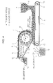
Fig. 8 , in the case where a large amount of powder and granular material a is supplied to a previously known magnetic separator and the layer thickness of the powder and granular material a increases, the following problem occurs. The micronized powder and granular material a is in the state in which ferromagnetic particles enclose non-magnetic particles, and the ferromagnetic particles and the non-magnetic particles are attracted by themagnet 22 at the same time, so that the ferromagnetic particles and the non-magnetic particles are not separated from each other easily. This becomes considerable as the particle diameter of the powder and granular material a decreases. Furthermore, an agglomeration phenomenon due to micronization is added, so that in the case where the layer thickness of the powder and granular material a on theconveyer belt 20 increases, as shown inFig. 8 , non-magnetic particles are also allowed to enter the magnetically attractedmaterial recovery portion 24x, and the ferromagnetic particles cannot be separated appropriately. - It is necessary to deal with the above-described problem usually in such a way that, for example, as shown in
Fig. 9 , the amount of supply of powder and granular material a is decreased by utilizing a vibratingfeeder 26 or the like to reduce the thickness of the powder and granular material layer on theconveyer belt 20 to, such as, the thickness of about one or two particles. However, if the amount of supply of the powder and granular material a is decreased, the treatment speed is reduced, although the performance to separate the ferromagnetic particles is ensured. In the case of magnetic separation of a slag, several tons to several tens of tons per hour of treatment is necessary and, therefore, it is indispensable to perform a large amount of magnetic separation in a short time. Consequently, it is difficult for the above-described previously known magnetic separator to magnetically separate a large amount of powder and granular material a in a short time. - On the other hand,
PTL 1 proposes a method in which foreign matters are separated without over-crushing the slag by undergoing a plurality of specific steps. However, there is a problem that the separation flow becomes complicated and the treatment cost increases. Also, as shown inPTL 2, a wet process is commonly applied in order to avoid agglomeration, but there is a problem that a waste fluid disposal cost increases considerably. - It is an object of the present invention to solve the above-described issues in the related conventional art and provide a magnetic separator and a magnetic separation method, where ferromagnetic particles are separated from a powder and granular material efficiently and magnetic separation can be performed at a low cost without the need for complicated steps and waste fluid disposal even in the case where a large amount of powder and granular material containing ferromagnetic particles is treated and in the case where the layer of a supplied powder and granular material is thick.
- The present inventors obtained the following findings on the magnetic separation.
- In the case where ferromagnetic particles are separated from a powder and granular material, in which ferromagnetic particles and non-magnetic particles are mixed, through the use of moving magnets, when the movement of each particle is observed, initially, the ferromagnetic particle is moved in such a way as to be attracted by the magnet. The attractive force that acts on the ferromagnetic particle is changed on the basis of the change in the strength of the magnetic field in association with the movement of the magnet. When the magnetic field is strong, the ferromagnetic particles are gathered together on the basis of the attractive force. Conversely, when the magnetic field is weak, there is a tendency to disperse.
- This change in the attractive force exerts an effect like vibration on the powder and granular material. The state of sandwiching and enclosure of non-magnetic particles by ferromagnetic particles is resolved on the basis of repetition of the change in the strength of the magnetic field. As a result, separation of the ferromagnetic particles from the non-magnetic particles is facilitated. Furthermore, the torque is added to the ferromagnetic particles on the basis of changes in the direction of the magnetic field, so that the ferromagnetic particles are moved between the non-magnetic particles toward the magnet side while being rotated. Most of the ferromagnetic particles are gathered gradually in the vicinity of the magnet by these two effects, and the non-magnetic particles are moved to the side farther from the magnet conversely. In this manner, the ferromagnetic particles can be separated from the non-magnetic particles by utilizing the changes in the strength and the direction of the magnetic field.
-
Fig. 1 (A) to (D) schematically show the above-described actions. InFig. 1 (A) to (D) , the magnetic poles of the magnet of the portion facing the powder and granular material are referred to as the north pole and the south pole. When the magnet is moved from the state in which the ferromagnetic particles on theconveyer belt 2 are attracted by the north pole, as shown inFig. 1 (A) , to the state in which a space portion between the north pole and the south pole faces the powder and granular material, as shown inFig. 1 (B) , the magnitude of the attractive force acted on the ferromagnetic particles is changed because of the strength of the magnetic field. Also, the ferromagnetic particles are attracted in the direction of arrows because of the change in the magnetic pole from the north pole to the south pole and are moved to the magnet side while being rolled. Thereafter, as shown inFig. 1 (C) , the ferromagnetic particles are attracted by the south pole and are further moved to the magnet side. The above-described actions are repeated and, thereby, the ferromagnetic particles originally distributed in the whole powder and granular material layer are gathered to the side nearest to the magnet in the powder and granular material layer, as shown inFig. 1 (D) . - This phenomenon always occurs if at least one of the magnet and the powder and granular material a is moved, and the same goes for the case where the magnet is fixed and only the powder and granular material a is moved.
- In the case where the magnets are moved while the same magnetic poles are arranged side by side, movement of the ferromagnetic particles due to the changes in the strength of the magnetic field occur but the amounts of movement of the ferromagnetic particles are reduced because the torque due to the changes in the direction of the magnetic field is not added to the ferromagnetic particles. As a result, the separation efficiency is reduced.
- In this regard,
Fig. 1 (A) to (D) show the case where the magnets are moved from the right side to the left side in the drawing, although the same goes for the case where the magnets are moved from the left side to the right side in the drawing, in theory. - The present inventors found that the ferromagnetic particles were able to be magnetically separated efficiently by applying the above-described mechanism to a belt conveyer style magnetic separator, disposing magnets inside the belt guide roll on the conveyer end edge side in such a way that adjacent magnetic poles in the portion facing the powder and granular material were arranged to become different from each other along the circumferential direction of the belt guide roll and, in addition, in such a way that adjacent magnetic poles in the portion facing the powder and granular material were arranged to become the same in the width direction of the belt guide roll, and moving the powder and granular material in the magnetic field formed by these magnets. The effect is further enhanced by rotating the magnets and, thereby, changing the strength and the direction of the magnetic field acted on the ferromagnetic particles at a high speed.
- The present invention has been made on the basis of the above-described findings and the gist is as described below.
- [1] A magnetic separator including
- a conveyer belt to carry a powder and granular material containing ferromagnetic particles,
- a rotatable hollow belt guide roll having an outer circumference partly wound with the above-described or an other conveyer belt, and
- a magnetic field application device disposed inside the above-described belt guide roll,
- wherein the above-described magnetic field application device includes a plurality of magnets inside the above-described belt guide roll, and
- the above-described magnets are arranged in such a way that magnetic poles adjacent in the circumferential direction of the above-described belt guide roll are different from each other and, in addition, are arranged in such a way that adjacent magnetic poles in the width direction of the above-described belt guide roll are the same.
- [2] The magnetic separator according to
Claim 1, wherein
the magnetic field change frequency F (Hz), which is defined by the following formula (1) and which indicates the number of changes in magnetic poles acted on the powder and granular material from the above-described magnetic field application device, is 170 Hz or more.
- where x: the number of revolutions per minute of magnet roll (rpm)
- P: the number of magnetic poles provided to magnet roll (in this regard, as for the number of magnetic poles, a pair of the north pole and the south pole adjacent in the circumferential direction of the surface facing the powder and granular material (a) of the
magnet roll 4r is counted as one magnetic pole)
- [3] The magnetic separator according to the item [1] or the item [2], including
- a first belt conveyer (A) to carry the powder and granular material containing ferromagnetic particles,
- a second belt conveyer (B) located above the belt conveyer, and
- a magnetic field application device, which is provided with a plurality of magnets arranged in the belt guide roll circumferential direction, inside the belt guide roll at the conveyer start edge portion side of the above-described belt conveyer (B),
- wherein the conveyer start edge portion of the above-described belt conveyer (B) is closely located above the conveyer end edge portion of the above-described belt conveyer (A), and
- the above-described magnets are arranged in such a way that magnetic poles adjacent in the circumferential direction of the above-described belt guide roll of the above-described belt conveyer (B) are different from each other and, in addition, are arranged in such a way that adjacent magnetic poles in the width direction of the above-described belt guide roll of the above-described belt conveyer (B) are the same.
- [4] The magnetic separator according to the item [1] or the item [2], including
- a first belt conveyer (A) to carry the powder and granular material containing ferromagnetic particles and
- a second belt conveyer (B) located above the above-described belt conveyer (A),
- wherein the conveyer start edge portion of the above-described belt conveyer (B) is closely located above the conveyer end edge portion of the above-described belt conveyer (A),
- the conveyer belts of the above-described belt conveyers (A) and (B) are moved in the same direction in the conveyer end edge portion of the above-described belt conveyer (A) and the conveyer start edge portion of the above-described belt conveyer (B),
- the above-described magnetic field application device is provided with a plurality of magnets arranged in the belt guide roll circumferential direction and width direction inside the belt guide roll on the conveyer start edge portion side of the above-described belt conveyer (B) and, in addition,
- the above-described magnets are arranged in such a way that magnetic poles adjacent in the above-described belt guide roll circumferential direction of the above-described belt conveyer (B) are different from each other and
- are arranged in such a way that magnetic poles adjacent in the above-described belt guide roll width direction of the above-described belt conveyer (B) are the same.
- [5] The magnetic separator according to the item [1] or the item [2], including
- a first belt conveyer (A) to carry the powder and granular material containing ferromagnetic particles,
- a second belt conveyer (B) located above the belt conveyer (A), and
- a magnetic field application device provided with a plurality of magnets inside the belt guide roll at the conveyer start edge portion side of the above-described belt conveyer (B),
- wherein the conveyer start edge portion of the above-described belt conveyer (B) is closely located above the conveyer belt of the above-described belt conveyer (A) and between the conveyer end edge portion of the belt conveyer (A) and a powder and granular material supply device,
- the conveyer belts of the above-described belt conveyers (A) and (B) are moved in the directions reverse to each other in the conveyer end edge portion of the above-described belt conveyer (A) and the conveyer start edge portion of the above-described belt conveyer (B), and
- the above-described magnets are arranged in such a way that magnetic poles adjacent in the above-described belt guide roll circumferential direction of the above-described belt conveyer (B) are different from each other and, in addition, are arranged in such a way that magnetic poles adjacent in the above-described belt guide roll width direction of the above-described belt conveyer (B) are the same.
- [6] The magnetic separator according to any one of the items [3] to [5],
wherein the above-described magnetic field application device of the above-described belt conveyer (B) is formed from a rotatable magnet roll disposed inside the above-described belt guide roll, and
the magnets disposed along the outer circumference of the above-described magnet roll are arranged in such a way that magnetic poles adjacent in the above-described belt guide roll circumferential direction of the above-described belt conveyer (B) are different from each other and, in addition, are arranged in such a way that magnetic poles adjacent in the above-described belt guide roll width direction of the above-described belt conveyer (B) are the same. - [7] The magnetic separator according to any one of the items [3] to [6], wherein a magnetically attracted material recovery portion is disposed below the conveyer end edge portion of the above-described belt conveyer (B) and a magnetically not-attracted material recovery portion is disposed below the conveyer start edge portion of the above-described belt conveyer (B).
- [8] A magnetic separation method comprising the steps of
using the magnetic separator according to any one of the items [3] to [7], and
supplying a powder and granular material from a supply device onto the above-described belt conveyer (A) with a layer thickness larger than the diameter of the smallest particle contained in the powder and granular material. - [9] The magnetic separator according to the item [1] or the item [2], including the conveyer belt to carry the powder and granular material containing ferromagnetic particles and the belt guide roll,
wherein a magnet roll which rotates in the direction reverse to the direction of the above-described belt guide roll is disposed inside the above-described belt guide roll, and
the magnet roll includes magnets arranged in such a way that magnetic poles adjacent in the above-described belt guide roll circumferential direction of the above-described belt conveyer (B) are different from each other and, in addition, arranged in such a way that magnetic poles adjacent in the above-described belt guide roll width direction of the above-described belt conveyer (B) are the same. - [10] The magnetic separator according to the item [9], wherein a partition plate is disposed below the above-described belt guide roll and along the above-described conveyer belt width direction and, in addition, a clearance for allowing the passage of part of the powder and granular material is disposed between the upper edge portion of the above-described partition plate and the above-described conveyer belt, and
a magnetically attracted material recovery portion and a magnetically not-attracted material recovery portion are disposed at positions sandwiching the above-described partition plate in the conveyer belt movement direction. - [11] A magnetic separation method including the steps of
using the magnetic separator according to the item [9] or the item [10], and
supplying a powder and granular material from a supply device onto the conveyer belt with a layer thickness larger than the diameter of the smallest particle contained in the powder and granular material. - [12] The magnetic separation method according to the item [11], wherein the clearance between the upper edge portion of the above-described partition plate and the conveyer belt is specified to be smaller than the layer thickness of the powder and granular material supplied to the above-described conveyer belt from the above-described supply device.
- [13] A magnetic separator to magnetically separate ferromagnetic particles from a powder and granular material (a) containing the ferromagnetic particles, including
a first belt conveyer (A) to carry the powder and granular material (a) and a second belt conveyer (B) which is located above the belt conveyer (A) and which attracts and separates the ferromagnetic particles, by a magnetic force, from the powder and granular material (a) carried with the belt conveyer (A),
wherein the movement directions of the conveyer belts (1) and (2) of the belt conveyers (A) and (B) are reverse to each other,
the conveyer start edge portion (11) of the belt conveyer (B) is closely located above the conveyer end edge portion (10) of the belt conveyer (A), and
a magnetic field application device (4) provided with a plurality of magnetic poles (5) arranged along the roll circumferential direction at a predetermined interval, where magnetic poles (5) adjacent in the roll circumferential direction are different from each other, is disposed inside the belt guide roll (3) at the conveyer start edge portion (11) side of the belt conveyer (B). - [14] The magnetic separator according to the item [13],
wherein the magnetic field application device (4) of the belt conveyer (B) is formed from a magnet roll (4r) driven to rotate and disposed inside the belt guide roll (3), the magnet roll (4r) is provided with a plurality of magnetic poles (5) arranged along the outer circumference thereof at a predetermined interval, magnetic poles (5) adjacent in the roll circumferential direction are different from each other, and
the conveyer belt (2) and the belt guide roll (3) of the belt conveyer (B) are made from a non-metal and, in addition, the belt guide roll (3) is specified to be a non-driven roll. - [15] The magnetic separator according to the item [13] or the item [14],
wherein a magnetically attracted material recovery portion (7x) is disposed below the conveyer end edge portion (12) of the belt conveyer (B), and
a magnetically not-attracted material recovery portion (7y) is disposed below the conveyer start edge portion (11) of the belt conveyer (B). - [16] A magnetic separation method for magnetically separating ferromagnetic particles from a powder and granular material (a) containing the ferromagnetic particles by using the magnetic separator according to any one of the items [13] to [15], the method comprising the step of
supplying the powder and granular material (a) from a supply device (6) onto the belt conveyer (A) with a layer thickness larger than the diameter of the smallest particle contained in the powder and granular material (a). - [17] The magnetic separation method according to
Claim 4,
wherein the magnetic separator according to the item [14] or the item [15] is used and the magnetic field change frequency F (Hz), which is defined by the following formula (1), of the magnet roll (4r) is specified to be 170 Hz or more.
- where x: the number of revolutions per minute of magnet roll (4r) (rpm)
- P: the number of magnetic poles provided to magnet roll (4r) (in this regard, a pair of the north pole and the south pole is counted as one magnetic pole)
- [18] A magnetic separator which is a conveyer style magnetic separator to supply a powder and granular material (a) containing ferromagnetic particles from a supply device (204) onto a conveyer belt (201) and attract and separate the ferromagnetic particles, by a magnetic force, from non-magnetic particles when the powder and granular material (a) is discharged from a conveyer end edge portion (2010),
wherein the conveyer belt (201) and the belt guide roll (202) at the conveyer end edge portion (2010) side are made from a non-metal and, in addition, the belt guide roll (202) is specified to be a non-driven roll, and
a magnet roll (203) driven to rotate in the direction reverse to the direction of the belt guide roll (202) is disposed inside the belt guide roll (202), the magnet roll (203) is provided with a plurality of magnetic poles (205) arranged along the outer circumference thereof at a predetermined interval and, in addition, magnetic poles (205) adjacent in the roll circumferential direction are different from each other. - [19] The magnetic separator according to the item [18], wherein a partition plate (206) is disposed below the belt guide roll (202) and along the conveyer belt width direction and, in addition, a clearance (S) for allowing the passage of part of the powder and granular material is disposed between the upper edge portion of the partition plate (206) and the conveyer belt (201), and
a magnetically attracted material recovery portion (207x) and a magnetically not-attracted material recovery portion (207y) are disposed at positions sandwiching the partition plate (206) in the conveyer belt movement direction. - [20] A magnetic separation method for magnetically separating ferromagnetic particles from a powder and granular material (a) containing the ferromagnetic particles by using the magnetic separator according to the item [18] or the item [19], the method comprising the step of
supplying the powder and granular material (a) from a supply device (204) onto the conveyer belt (201) with a layer thickness larger than the diameter of the smallest particle contained in the powder and granular material (a). - [21] The magnetic separation method according to the item [20], wherein the clearance (S) between the upper edge portion of the partition plate (206) and the conveyer belt (201) is specified to be smaller than the layer thickness of the powder and granular material supplied from the supply device (204) onto the conveyer belt (201).
- [22] The magnetic separation method according to the item [20] or the item [21],
wherein the magnetic field change frequency F (Hz), which is defined by the following formula (1), of the magnet roll is specified to be 170 Hz or more.
- where x: the number of revolutions per minute of magnet roll (rpm)
- P: the number of magnetic poles provided to magnet roll (in this regard, a pair of the north pole and the south pole is counted as one magnetic pole)
- [23] A method for manufacturing an iron source to produce the iron source from a by-product of an ironmaking process, including the step of using the magnetic separator or the magnetic separation method according to any one of the items [1] to [22].
- According to the present invention, ferromagnetic particles are separated from a powder and granular material containing the ferromagnetic particles in one separation step efficiently and magnetic separation can be performed at a low cost without the need for complicated steps, waste fluid disposal, and the like even in the case where a large amount of powder and granular material containing ferromagnetic particles is treated and in the case where the layer of a supplied powder and granular material is thick.
-
- [
Fig. 1] Fig. 1 (A) to (D) are explanatory diagrams schematically showing actions of a magnetic separator according to the present invention. - [
Fig. 2] Fig. 2 is an explanatory diagram showing a magnetic separator according to a first embodiment of the present invention and an embodiment of a magnetic separation method by using this apparatus. - [
Fig. 3] Fig. 3 is a perspective view showing the structure of a belt guide roll of the magnetic separator according to the first embodiment shown inFig. 2 . - [
Fig. 4] Fig. 4 is an explanatory diagram showing a modified example 1 of the magnetic separator according to the first embodiment of the present invention and a magnetic separation method by using this apparatus. - [
Fig. 5] Fig. 5 is an explanatory diagram showing a modified example 2 of the magnetic separator according to the first embodiment of the present invention and a magnetic separation method by using this apparatus. - [
Fig. 6] Fig. 6 is a perspective view showing the structure of a belt guide roll of a modified example 3 of the magnetic separator according to the first embodiment shown inFig. 2 . - [
Fig. 7] Fig. 7 is an explanatory diagram showing a magnetic separator according to a second embodiment of the present invention and an embodiment of a magnetic separation method by using this apparatus. - [
Fig. 8] Fig. 8 is an explanatory diagram showing a magnetic separator in the related conventional art and a state of use in the case where a large amount of powder and granular material is treated by using this apparatus. - [
Fig. 9] Fig. 9 is an explanatory diagram showing a magnetic separator in the related conventional art and a state of use in the case where a small amount of powder and granular material is treated by using this apparatus. - A magnetic separator and a magnetic separation method according to the present invention are to separate ferromagnetic particles from a powder and granular material containing the ferromagnetic particles by a magnetic force. The magnetic separator according to the present invention includes a belt to carry the powder and granular material, a rotatable belt guide roll having an outer circumference partly wound with the above-described or an other belt, and a magnetic field application device provided with a plurality of magnets disposed inside the guide roll. The magnets are arranged in such a way that the magnetic poles of the portion facing the powder and granular material come into alternate sequence along the circumferential direction of the belt guide roll and, in addition, are arranged in such a way that the magnetic poles of the portion facing the powder and granular material become the same in the width direction of the belt guide roll. In the case where the magnetic poles are the same in the width direction, a uniform magnetic field is formed and the force acted on the ferromagnetic particles also becomes uniform, and the separation efficiency of the ferromagnetic particles can be enhanced.
- The magnetic separation method according to the present invention separates ferromagnetic particles from a powder and granular material containing the ferromagnetic particles by using the magnetic separator having the above-described configuration.
- In the magnetic separator and the magnetic separation method according to the present invention, the magnetic field change frequency F (Hz), which is defined by the following formula (1) and which indicates changes in the strength of the magnetic field acted on the powder and granular material from the magnetic field application device, is specified to be 170 Hz or more. The magnetic field change frequency F is more preferably 200 Hz or more.

- where x: the number of revolutions per minute of magnet roll (rpm)
- P: the number of magnetic poles provided to magnet roll and disposed in the circumferential direction of magnet roll (in this regard, as for the number of magnetic poles, a pair of the north pole and the south pole adjacent in the circumferential direction of the surface facing the powder and granular material (a) of the
magnet roll 4r is counted as one magnetic pole and, for example, in the case where the north pole [a], the south pole [b], and the north pole [c] are aligned in the circumferential direction, the pair of the north pole [a] and the south pole [b] is counted as one magnetic pole and the pair of the south pole [b] and the north pole [c] is counted as one magnetic pole) - High-speed changes in the strength and the direction of the magnetic field acted on the powder and granular material are allowed to occur by specifying the magnetic field change frequency F (Hz) of the magnetic field application device to be 170 Hz or more, and preferably 200 Hz or more, so that it becomes possible to separate the ferromagnetic particles contained in the powder and granular material accurately.
-
Fig. 2 is an explanatory diagram showing a magnetic separator according to a first embodiment of the present invention and an embodiment of a magnetic separation method by using this apparatus. - The apparatus according to the first embodiment includes a first belt conveyer A to carry a powder and granular material (a) and a second belt conveyer B which is located above the belt conveyer A and which attracts and separates ferromagnetic particles, by magnets, from the powder and granular material a carried with the belt conveyer A.
- In the first belt conveyer A,
reference numeral 1 denotes a conveyer belt,reference numeral 8 denotes a belt guide roll on the conveyer startedge portion 14 side, andreference numeral 9 denotes a belt guide roll on the conveyerend edge portion 10 side. Theconveyer belt 1 is disposed between the belt guide rolls 8 and 9 and, thereby, the belt conveyer A is constructed. - In the second belt conveyer B,
reference numeral 2 denotes a conveyer belt,reference numeral 3 denotes a belt guide roll at the conveyer startedge portion 11 side, andreference numeral 13 denotes a belt guide roll at the conveyerend edge portion 12 side. Theconveyer belt 2 is disposed between the belt guide rolls 3 and 13 and, thereby, the belt conveyer B is constructed. In the present first embodiment, thebelt guide roll 3 is configured to have a diameter larger than the diameter of thebelt guide roll 13 and the axis of rotation of thebelt guide roll 13 is located upper than the axis of rotation of thebelt guide roll 3, so that the upper surface of the conveyer belt 2 (an upper belt portion between the belt guide rolls 3 and 13) is almost horizontal. However, the upper surface of theconveyer belt 2 may come down toward thebelt guide roll 13. - A
supply device 6 to supply the powder and granular material a containing the ferromagnetic particles is disposed above theconveyer belt 1 and at the position near to the conveyer startedge portion 14 of the belt conveyer A. - The ferromagnetic particles attracted and held on the belt conveyer B side are carried with the belt conveyer B and, thereafter, discharged from the conveyer
end edge portion 12. Therefore, a magnetically attractedmaterial recovery portion 7x is disposed below the conveyerend edge portion 12 of the belt conveyer B. Also, non-magnetic particles fall below the conveyer startedge portion 11 of the belt conveyer B, so that a magnetically not-attractedmaterial recovery portion 7y is disposed at that position. - In the first embodiment shown in
Fig. 2 , the conveyer startedge portion 11 of the belt conveyer B is closely located above the conveyerend edge portion 10 of the belt conveyer A. In this regard, the belt guide rolls 8 and 9 of the belt conveyer A and the belt guide rolls 3 and 13 of the belt conveyer B are rotated in the directions reverse to each other and theconveyer belts end edge portion 10 of the belt conveyer A and the conveyer startedge portion 11 of the belt conveyer B. - In the belt conveyer B, any one of the belt guide rolls 3 and 13 may be a driven roll driven by a drive device, e.g., a motor. However, usually, the
belt guide roll 13 is a driven roll and thebelt guide roll 3 is a non-driven roll. Thebelt guide roll 3 is formed from a sleeve body with a hollow inside and is rotatably supported. - In the first embodiment, a
magnet roll 4r serving as a magnetic field application device provided with a plurality ofmagnets 5 is disposed inside thebelt guide roll 3. Themagnet roll 4r is configured to be be able to rotate independently of thebelt guide roll 3. - As shown in
Fig. 3 described later, in the first embodiment, themagnet roll 4r is provided with the plurality ofmagnets 5 at predetermined intervals in the circumferential direction and the width direction of thebelt guide roll 3. The plurality ofmagnets 5 are arranged with magnetic poles aligned in such a way that alternating north poles and south poles adjoin over 360°C in the roll circumference direction of themagnet roll 4r. Also, the plurality ofmagnets 5 are arranged in such a way that the same magnetic poles are aligned in the width direction of themagnet roll 4r. - The number of
magnets 5 arranged in the roll circumferential direction, the interval of themagnets 5, and the like are not specifically limited. Higher speed of changes in the strength and the direction of the magnetic field are obtained by increasing the number of themagnets 5 or reducing the interval of themagnets 5. Put another way, high-speed changes in the magnetic field are obtained even when the rotational speed of themagnet roll 4r is low. - The strength of the magnetic field due to the
magnets 5 is not specifically limited. Usually, themagnets 5 are selected in such a way that about 0.01 to 0.5 T is ensured in the conveyer belt portion in contact with thebelt guide roll 3 in accordance with an object. If the magnetic field is too weak, the effect of themagnet roll 4r is not obtained sufficiently. On the other hand, if the magnetic field is too strong, the attractive force acted on the ferromagnetic particles is too strong and, on the contrary, separation of the ferromagnetic particles may be hindered. - Meanwhile, in the apparatus according to the first embodiment, the magnetic field is switched in the manner of strong → weak → strong → weak → ··· and the effect on the ferromagnetic particles in the powder and granular material layer is repeated in the manner of gathering → dispersion → gathering → dispersion → ··· because of the plurality of
magnets 5 arranged at the predetermined interval and the space portions betweenadjacent magnets 5. The width of space portions betweenmagnets 5 adjacent in the circumferential direction is not specifically limited, although about 1 to 50 mm is appropriate to obtain the above-described effects. -
Fig. 3 is a perspective view showing the structure of the belt guide roll of the magnetic separator according to the first embodiment shown inFig. 2 . Themagnet roll 4r provided with the plurality of magnets is disposed inside thebelt guide roll 3.Reference numeral 40 denotes a roll shaft of themagnet roll 4r.Roll shafts 30 at both ends of thebelt guide roll 3 are allowed to cover theroll shaft 40 of themagnet roll 4r disposed inside thebelt guide roll 3 and are fitted to theroll shaft 40 with a bearing 15 (metal bearing, roller bearing, or the like) therebetween. However, thebelt guide roll 3 and themagnet roll 4r can be rotated independently of each other and theroll shaft 30 and theroll shaft 40 can take various forms. - The
magnet roll 4r is a roll rotated by a device, e.g., a motor, and the rotational direction thereof may be the same as or reverse to the direction of thebelt guide roll 3. In general, the rotation is in the direction reverse to the direction of thebelt guide roll 3. In this regard, themagnet roll 4r is rotated at a speed higher than the speed of thebelt guide roll 3. - In the present first embodiment, it is preferable that changes in the magnetic field occur at a maximized speed (high-speed changes in the strength and the direction of the magnetic field). Specifically, as described above, the magnetic field change frequency F (Hz), which is defined by the following formula (1), of the
magnet roll 4r is specified to be preferably 170 Hz or more. The magnetic field change frequency is more preferably 200 Hz or more.
- where x: the number of revolutions per minute of
magnet roll 4r (rpm) - P: the number of magnetic poles provided to
magnet roll 4r (in this regard, as for the number of magnetic poles, a pair of the north pole and the south pole adjacent in the circumferential direction of the surface facing the powder and granular material (a) of themagnet roll 4r is counted as one magnetic pole) and, for example, in the case where the north pole [a], the south pole [b], and the north pole [c] are aligned in the circumferential direction, the pair of the north pole [a] and the south pole [b] is counted as one magnetic pole and the pair of the south pole [b] and the north pole [c] is counted as one magnetic pole. For example, in the case where 12 poles (a pair of the north pole and the south pole is counted as one magnetic pole) of magnets (for example, neodymium magnets) are disposed in the circumferential direction, when the rotational speed of themagnet roll 4r is specified to be 1,000 rpm, the magnetic field change frequency results in 200 Hz. Also, in the case where 24 poles (a pair of the north pole and the south pole is counted as one magnetic pole) of magnets are disposed in the circumferential direction and the magnetic field change frequency is specified to be 200 Hz likewise, the rotational speed of themagnet roll 4r may be 500 rpm. - The upper limit of the magnetic field change frequency is about 1,000 Hz because there is a mechanical upper limit to the number of revolutions per minute of the
magnet roll 4r and the effect of changes in the magnetic field may be saturated even when the frequency is increased. - The size of the
magnet 5 is not specifically limited insofar as the size is suitable for arranging the predetermined number ofmagnets 5. In this regard, inFig. 2 , the magnetic poles of onemagnet 5 are arranged in such a way that the magnetic pole on the inner circumferential side of themagnet roll 4r is different from the magnetic pole on the outer circumferential side. However, as a matter of course, themagnets 5 may be disposed in such a way that the different magnetic poles of onemagnet 5 are arranged in the circumferential direction of themagnet roll 4r. In this case as well, the north pole and the south pole are disposed alternately, so that the ferromagnetic particles can be separated efficiently. The north pole and the south pole may be disposed with a space portion therebetween. Alternatively, the north poles may be disposed with a space portion therebetween and the south poles may be disposed with a space portion therebetween. - In addition, the space portions between the
magnets 5 may be filled with a resin or the like, and a cover may be attached to the outer circumference of themagnet roll 4r. - The rotational direction of the
magnet roll 4r may be either (i) the direction reverse to the movement direction of the conveyer belt 2 (the rotational direction of the belt guide roll 3) or (ii) the same direction as the movement direction of the conveyer belt 2 (the rotational direction of the belt guide roll 3). A carrying force is exerted on the ferromagnetic particles to move in the direction reverse to the rotational direction of themagnet roll 4r because of the action of the magnetic field of therotating magnet roll 4r. In the case of the above-described item (i), the carrying force exerted on the ferromagnetic particles by the magnetic field and the frictional force between theconveyer belt 2 and the ferromagnetic particles become the same direction. On the other hand, in the case of the above-described item (ii), the directions of the above-described carrying force and frictional force become reverse to each other. However, the frictional force is larger in this case and, therefore, the ferromagnetic particles are carried in the movement direction of theconveyer belt 2. - When the item (i) and the item (ii) are compared, in the case of the item (ii), the directions of the carrying force exerted on the ferromagnetic particles by the magnetic field and the frictional force between the
conveyer belt 2 and the ferromagnetic particles become reverse to each other, so that the ferromagnetic particles may stay on theconveyer belt 2, although the ferromagnetic particles can be separated more efficiently. On the other hand, in the case of the item (i), the ferromagnetic particle separation efficiency is slightly lower than that in the case of the item (ii), but the ferromagnetic particles do not stay on theconveyer belt 2 and, therefore, there is an advantage that the particles can be carried smoothly. - The function and the operation of the magnetic separator according to the present first embodiment and the magnetic separation method by using this apparatus will be described below.
- In the magnetic separator according to the present first embodiment, the belt feed speeds of the
conveyer belts Fig. 2 , the rotational speed of themagnet roll 4r is determined in such a way that the speed of changes in the magnetic field becomes sufficiently high relative to this belt feed speed. In particular, it is preferable that the rotational speed of themagnet roll 4r be set in such a way as to satisfy the above-described condition represented by the formula (1). - A sufficient thickness of powder and granular material a containing the ferromagnetic particles is supplied from the
supply device 6 to the movingconveyer belt 1 of the belt conveyer A, while the belt conveyers A and B are operated. This powder and granular material a is carried to the conveyerend edge portion 10. The upper surface of the powder and granular material a carried with theconveyer belt 1 is brought into contact with the lower surface of the conveyer startedge portion 11 of the belt conveyer B in the vicinity of the conveyerend edge portion 10, and the powder and granular material a slips between the conveyerend edge portion 10 of the belt conveyer A and the conveyer startedge portion 11 of the belt conveyer B. At this time, the magnetic field of the magneticfield application device 4 of the belt conveyer B is exerted on the powder and granular material a. - In this regard, in the case of the magnetic separator shown in
Fig. 2 , the ferromagnetic particles in the form of enclosing non-magnetic particles in the powder and granular material a are attached to the lower surface side of the belt conveyer B because of the magnetic force of themagnet roll 4r serving as the magneticfield application device 4 and are carried with theconveyer belt 2. The ferromagnetic particles in the powder and granular material a undergo action of the magnetic field of themagnets 5 included in themagnet roll 4r and the strength of the magnetic field is switched in the manner of strong → weak → strong → weak → ··· instantaneously because of the rotation of themagnet roll 4r. The effect in the manner of gathering → dispersion → gathering → dispersion → ··· is repeated on the ferromagnetic particles in the powder and granular material layer. - Also, in the case where the magnetic field application device is formed from the magnet roll 4r which is rotated independently of the belt guide roll 3, as in the embodiment shown in
Fig. 2 , the ferromagnetic particles can be efficiently magnetically separated even when the thickness of the powder and granular material a supplied to the conveyer belt 1 is sufficiently increased, as shown inFig. 2 , because of the functions of (1) mechanically generating high-speed changes in the magnetic field by rotating the magnet roll 4r, (2) supplying the powder and granular material a with a sufficient layer thickness into the resulting changing magnetic field, (3) moving the ferromagnetic particles to the magnet roll 4r side and excluding the non-magnetic particles to the side apart from the magnet roll 4r while entanglement and enclosure of the non-magnetic particles by the ferromagnetic particles are resolved on the basis of changes in the magnetic field, and (4) allowing the non-magnetic particles to fall by gravity at the conveyer start edge portion 11 of the belt conveyer B and carrying the ferromagnetic particles in the state of being attracted and held by the belt conveyer B to discharge in the conveyer end edge portion 12 of the belt conveyer B. As shown inFig. 2 , the ferromagnetic particles can be magnetically separated from the powder and granular material a efficiently, even if the thickness of the powder and granular material a supplied to the conveyer belt 1 is large. That is, the ferromagnetic particles can be magnetically separated from the powder and granular material a efficiently and quickly. - In this regard, in the apparatus according to the first embodiment shown in
Fig. 2 , themagnet roll 4r is rotated and, thereby, 100 times or more in number of changes in the strength and the direction of the magnetic field are given easily while the powder and granular material a is carried along thebelt guide roll 3 of the belt conveyer B. In addition, the behavior of the ferromagnetic particles in the magnetic field is changed depending on the powder and granular material a concerned, so that the number of revolutions per minute of themagnet roll 4r can be adjusted to obtain appropriate performance. - Even the apparatus in the related conventional art, as shown in
Fig. 8 , exerts an effect of separating the ferromagnetic particles in the powder and granular material a because there are changes in the strength and the direction of the magnetic field corresponding to the number of magnets. However, there is a limit to the number of changes in the magnetic field (several times to ten-odd times) because of stationary magnets, and the effects of separating the ferromagnetic particles is small. On the other hand, in the apparatus according to the present first embodiment, themagnet roll 4r is rotated and, therefore, 100 times or more in number of changes in the magnetic field are given easily while the powder and granular material is carried along theconveyer belt 2. - As described above, the magnetic separator according to the present first embodiment can magnetically separate the ferromagnetic particles from the powder and granular material a efficiently. Therefore, in magnetic separation of the powder and granular material a by using this apparatus, as shown in
Fig. 2 , it is desirable that the powder and granular material be supplied from thesupply device 6 to theconveyer belt 1 of the belt conveyer A with a layer thickness larger than the diameter of the smallest particle contained in the powder and granular material a and, in addition, with a layer thickness which allows the magnetic force to act sufficiently. Specifically, the thickness of the powder and granular material may be 20 to 30 mm. - The powder and granular material which is the object of magnetic separation by the apparatus according to the present first embodiment is not specifically limited. Examples thereof include slag, e.g., ironmaking slag, and tailing ores. Among them, in particular, application to the magnetic separation of slag is favorable.
- In the iron content recovery from the slag, initially, the ironmaking slag is micronized. If the micronization is insufficient, the recovery rate of the iron content is not improved. There are various steps in the ironmaking and steelmaking processes to generate the ironmaking slag, so that various types of slags are generated. The slag particle diameter after the micronization is determined depending on the slag. In many cases, micronization to several tens of micrometers to about 1 millimeter is required depending on the form of iron contained. The common method for micronization is crushing. Crushing with a jaw crusher or a hammer crusher is performed as rough crushing and, thereafter, crushing is performed by using a ball mill, a rod mill, a jet mill, a pin mill, an impact mill, or the like for the purpose of micronization. As for another method, a method in which heating to about 1,000°C to 1,300°C is performed and, thereafter, cooling is performed gradually is also mentioned.
- Then, magnetic separation is performed by the magnetic separator according to the present invention, where the object is the micronized slag. The iron content can be separated and recovered from the slag efficiently by the present invention.
- In the first embodiment shown in
Fig. 2 ,magnets 5 are disposed over the width direction of the belt guide roll 3 (magnet roll 4r) in such a way that the magnetic poles of the portion facing the powder and granular material a become the same. In the case where the same magnetic poles are arranged in the width direction, a uniform magnetic field is formed and a force acted on the ferromagnetic particles becomes uniform. However, if themagnets 5 are arranged in such a way that the magnetic poles are different in the width direction, the magnetic field becomes nonuniform and portions, where ferromagnetic particles are not separated, result locally, so that the separation efficiency is reduced. - The members around the rotating magnet roll are influenced by an eddy-current effect due to the changing magnetic field, and metal members, which are even non-magnetic materials, are heated by the eddy current. Consequently, the
conveyer belt 2 and thebelt guide roll 3 of the belt conveyer B according to the present embodiment are formed from nonmetal, e.g., resin or ceramics. - The apparatus according to the present first embodiment separates the ferromagnetic particles by allowing the magnetic field of the
magnet roll 4r disposed inside thebelt guide roll 3 on the conveyer startedge portion 11 side of the belt conveyer B to act on the powder and granular material a (powder and granular material layer) carried with the belt conveyer A and attracting and moving the ferromagnetic particles in the powder and granular material a to the lower surface side of the belt conveyer B. Therefore, the distance between the conveyerend edge portion 10 of the belt conveyer A and the conveyer startedge portion 11 of the belt conveyer B may be a dimension at which the magnetic force of themagnet roll 4r acts on the ferromagnetic particles in the powder and granular material a sufficiently. In general, the dimension at which the upper surface of the layer of the powder and granular material a carried with theconveyer belt 1 of the belt conveyer A comes into contact with the conveyer startedge portion 11 of the belt conveyer B, that is, the powder and granular material layer can be slipped between the conveyerend edge portion 10 of the belt conveyer A and the conveyer startedge portion 11 of the belt conveyer B, is preferable. - Next, the modified example 1 of the first embodiment according to the present invention will be described.
Fig. 4 is a diagram showing a magnetic separator according to the modified example 1 of the the first embodiment of the present invention. - In the modified example 1, the positional relationship between the belt conveyer A and the belt conveyer B is specified to be a form different from the form shown in
Fig. 1 . That is, the conveyer startedge portion 11 of the belt conveyer B is closely located above the conveyerend edge portion 10 of the belt conveyer A, and the belt guide rolls 8 and 9 of the belt conveyer A and the belt guide rolls 3 and 13 of the belt conveyer B are rotated in the same direction. Meanwhile, theconveyer belts end edge portion 10 of the belt conveyer A and the conveyer startedge portion 11 of the belt conveyer B. - As a matter of course, even in the case where such an arrangement is employed, the ferromagnetic particles can be separated. In this regard, the configuration other than the positional relationship between the belt conveyers A and B is substantially the same as the configuration of the first embodiment shown in
Figs. 2 and3 and, therefore, the explanations thereof will not be provided. - Next, the modified example 2 of the first embodiment according to the present invention will be described.
Fig. 5 is an explanatory diagram showing the modified example 2 of the magnetic separator according to the first embodiment of the present invention and a magnetic separation method by using this apparatus. - In the modified example 2 of the first embodiment, the
belt guide roll 3 is formed from a sleeve body with a hollow inside and is rotatably supported. A magneticfield application device 4 provided with a plurality ofmagnets 5, which are arranged at a predetermined interval along the roll circumferential direction, is disposed inside thebelt guide roll 3. - The magnetic
field application device 4 in the modified example 2 is not rotated in contrast to themagnet roll 4r in the first embodiment. Put another way, themagnets 5 of the magneticfield application device 4 are disposed independently of thebelt guide roll 3 and are stationary magnets which are not rotated. In this regard, as shown inFig. 3 , themagnets 5 of the magneticfield application device 4 are arranged in such a way that the magnetic poles adjacent in the roll circumferential direction are different from each other and, in addition, are arranged in such a way that the magnetic poles adjacent in the roll width direction are the same. - As shown in
Fig. 5 , in the modified example 2 of the first embodiment, the range of disposition of themagnets 5 in the roll circumferential direction is the range of at least about 180° (one-half the circumference of the belt guide roll 3) which is from the lower edge portion of the belt guide roll 3 (the position facing the conveyerend edge portion 10 of the belt conveyer A) to the top position of thebelt guide roll 3. The range of disposition of themagnets 5 can be reduced by disposing themagnets 5 in such a way that themagnets 5 are fixed and are not rotated, as in the example 2. - In the magnetic separator according to a second embodiment, the ferromagnetic particles in the powder and granular material a are attracted by the magnetic
field application device 4 provided withstationary magnets 5, and the powder and granular material a (or part thereof) having the form, in which the ferromagnetic particles enclose non-magnetic particles, is attached to (held by) the lower surface side of the belt conveyer B and are carried with theconveyer belt 2. In this apparatus as well, although the effect is small as compared with the effect of themagnet roll 4r shown inFig. 2 , the ferromagnetic particles in the powder and granular material a undergo action of the magnetic force of themagnets 5 included in the magneticfield application device 4 and the magnetic field is switched in the manner of strong → weak → strong → weak → ··· during carrying with theconveyer belt 2. Consequently, the manner of gathering → dispersion → gathering → dispersion → ··· is repeated with respect to the ferromagnetic particles in the powder and granular material a, so that the same quality of effect as with the first embodiment shown inFig. 2 is obtained. However, the magnetic field does not change at a high speed in contrast to themagnet roll 4r shown inFig. 2 and, therefore, the magnetic separability and the treatment speed are low as compared with those in the first embodiment shown inFig. 2 . - The magnetic separator according to the modified example 2 has operation advantages, such as, (i) in the adopted basic system, the magnetic field by the magnetic
field application device 4 included in the second belt conveyer B is acted on the powder and granular material a, which is discharged from the first belt conveyer A, from above to attract the ferromagnetic material contained in the powder and granular material a and move to the belt conveyer B side, so that enclosure and entanglement of the non-magnetic particles by the ferromagnetic particles can be reduced as compared with those of the apparatus in the related conventional art and, in addition, (ii) entanglement and enclosure of the non-magnetic particles by the ferromagnetic particles are resolved on the basis of changes in the magnetic field by the magneticfield application device 4. -
Fig. 6 is a perspective view showing the structure of a belt guide roll of a modified example 3 of the magnetic separator according to the first embodiment shown inFig. 2 . As shown inFig. 6 , in the example 3 of the first embodiment,magnets 5 are included in themagnet roll 4r, where a plurality ofmagnets 5 are disposed in the circumferential direction of the belt guide roll 3 (magnet roll 4r) and only onemagnet 5 is disposed in the width direction of the belt guide roll 3 (magnet roll 4r). Themagnets 5 are arranged in such a way that the magnetic poles facing the powder and granular material a come into alternate sequence along the circumferential direction. Themagnets 5 may have the above-described configuration. -
Fig. 7 is an explanatory diagram showing an embodiment of a magnetic separator according to a second embodiment of the present invention and a magnetic separation method by using this apparatus. - The magnetic separator according to the present second embodiment is a belt conveyer style magnetic separator as with the first embodiment. The magnetic separator according to the second embodiment supplies a powder and granular material (a) containing ferromagnetic particles from a supply device to a
conveyer belt 201 and attracts and separates the ferromagnetic particles, by a magnetic force, from non-magnetic particles when the powder and granular material a is discharged from a conveyerend edge portion 2010. - In
Fig. 7 ,reference numeral 201 denotes a conveyer belt,reference numeral 202 denotes a belt guide roll on the conveyerend edge portion 2010 side, andreference numeral 208 denotes a belt guide roll on the conveyer startedge portion 2011 side. Theconveyer belt 201 is disposed between the belt guide rolls 202 and 208 and, thereby, the belt conveyer is formed. Thebelt guide roll 208 is driven by a drive device, e.g., a motor, and thereby, theconveyer belt 201 is rotated in the belt conveyer. Thebelt guide roll 202 is a non-driven roll and is formed from a sleeve body with a hollow inside. - A
magnet roll 203 is disposed inside thebelt guide roll 202. The configuration of themagnet roll 203 is substantially the same as the configuration shown inFig. 3 . Specifically, themagnet roll 203 is provided with a plurality ofmagnets 205 arranged in the circumference direction and the width direction thereof at predetermined intervals and, in addition, the magnetic poles of themagnets 205 adjacent in the roll circumferential direction are different magnetic poles (north pole, south pole). That is,magnets 205 are arranged in such a way that the north poles and the south poles are arranged alternately in the roll circumference direction. The plurality ofmagnets 205 are arranged in such a way that the same magnetic poles are aligned in the roll width direction. - The
magnet roll 203 is a roll rotated by a motor or the like and is rotated in the direction reverse to the direction of thebelt guide roll 202. Also, as described later, thismagnet roll 203 is rotated at a speed higher than the speed of thebelt guide roll 202. - The members around the rotating magnet roll are influenced by an eddy-current effect due to the changing magnetic field, and metal members, which are even non-magnetic materials, are heated by the eddy current. Consequently, the
conveyer belt 201 and thebelt guide roll 202 are formed from a nonmetal, e.g., a resin or ceramics. - The
magnets 205 are arranged in such a way that the magnetic poles become the same over the width direction of themagnet roll 203. In the case where the same magnetic poles are arranged in the width direction, a uniform magnetic field is formed and a force acted on the ferromagnetic particles becomes uniform. However, if themagnets 205 are arranged in such a way that the magnetic poles are different in the width direction, the magnetic field becomes nonuniform and portions, where ferromagnetic particles are not separated, result locally, so that the separation efficiency is reduced. In this regard, as for themagnet 205, one magnet may be disposed in the width direction, as shown inFig. 6 , or appropriately divided magnets may be disposed, as shown inFig. 3 . - The number of
magnets 205 arranged along the outer circumference of themagnet roll 203, the arrangement interval, and the like are not specifically limited. High-speed changes in the magnetic field are obtained even when the rotational speed is low by increasing the number of themagnets 205 or reducing the arrangement interval. - In the second embodiment, as with the first embodiment, it is preferable that changes in the strength and the direction of the magnetic field be allowed to occur at a maximized speed. Specifically, the magnetic field change frequency F (Hz), which is defined by the following formula (1), of the
magnet roll 203 is preferably 170 Hz or more. The magnetic field change frequency is more preferably 200 Hz or more.
- where x: the number of revolutions per minute of magnet roll (rpm)
- P: the number of magnetic poles provided to magnet roll (in this regard, as for the number of magnetic poles, a pair of the north pole and the south pole adjacent in the circumferential direction of the surface facing the powder and granular material (a) of the
magnet roll 4r is counted as one magnetic pole and, for example, in the case where the north pole [a], the south pole [b], and the north pole [c] are aligned in the circumferential direction, the pair of the north pole [a] and the south pole [b] is counted as one magnetic pole and the pair of the south pole [b] and the north pole [c] is counted as one magnetic pole) - For example, in the case where 12 poles (a pair of the north pole and the south pole is counted as one magnetic pole) of magnets (for example, neodymium magnets) are disposed in the circumferential direction, when the rotational speed of the
magnet roll 203 is specified to be 1,000 rpm, the magnetic field change frequency results in 200 Hz. In the case where 24 poles (a pair of the north pole and the south pole is counted as one magnetic pole) of magnets are disposed in the circumferential direction and the magnetic field change frequency is specified to be 200 Hz likewise, the rotational speed of themagnet roll 203 may be 500 rpm. - The upper limit of the magnetic field change frequency is about 1,000 Hz because there is a mechanical upper limit to the number of revolutions per minute of the
magnet roll 203 and the effect of changes in the magnetic field may be saturated even when the frequency is increased. - The size of the
magnet 205 is not specifically limited insofar as the size is suitable for arranging the predetermined number of magnets. The strength of the magnetic field due to themagnets 205 is not specifically limited. Usually, themagnets 205 are selected in such a way that about 0.01 to 0.5 T is ensured in the conveyer belt portion in contact with thebelt guide roll 202 in accordance with an object. If the magnetic field is too weak, the effect of themagnet roll 203 is not obtained sufficiently. On the other hand, if the magnetic field is too strong, the attractive force acted on the ferromagnetic particles is too strong and separation of the ferromagnetic particles on the basis of the above-described principle (Fig. 1 (A) to (D) ) may be hindered conversely. - In the apparatus according to the present second embodiment as well, the basic function of separating the ferromagnetic particles is the same as that described with reference to
Fig. 1 . - It is the feature that when the
magnet roll 203 is rotated, the magnetic field is switched in the manner of strong → weak → strong → weak → ··· instantaneously and the effect on the ferromagnetic particles in the powder and granular material layer is repeated in the manner of gathering → dispersion → gathering → dispersion → ··· because of the plurality ofmagnets 205 arranged at the predetermined interval and the space portions betweenadjacent magnets 205. The width of space portions betweenadjacent magnets 205 in the roll circumferential direction is not specifically limited, although about 1 to 50 mm is appropriate in order that the state in which the ferromagnetic particles in the powder and granular material layer are released from the magnetic field occurs appropriately, whereas the state in which the magnetic field is weakened does not continue for a long time. - A
partition plate 6 is disposed below (just below) thebelt guide roll 202 and along the conveyer belt width direction. In addition, a clearance S for allowing the passage of the ferromagnetic particles is disposed between the upper edge portion of thepartition plate 206 and the conveyer belt 201 (conveyer belt portion with the movement direction reversed by the belt guide roll 202). Thepartition plate 206 is disposed in such a form for the purpose of avoiding mixing of the non-magnetic particles with the ferromagnetic particles during falling because the fall area of the non-magnetic particles and the fall area of the ferromagnetic particles are adjacent to each other. - Also, a magnetically attracted
material recovery portion 207x and a magnetically not-attractedmaterial recovery portion 207y are disposed at positions sandwiching thepartition plate 206 in the conveyer belt movement direction. That is, the magnetically attractedmaterial recovery portion 207x is disposed at the position on the conveyer startedge portion 2011 side (fall area of the ferromagnetic particles) and the magnetically not-attractedmaterial recovery portion 207y is disposed on the position of the conveyerend edge portion 2010 side (fall area of the non-magnetic particles), while thepartition plate 206 is sandwiched between them. - The function and the operation of the magnetic separator according to the present second embodiment and the magnetic separation method by using this apparatus will be described below.
- In the magnetic separator according to the present second embodiment, the belt feed speed of the conveyer belt 201 (rotational speeds of the belt guide rolls 202 and 208) may be specified to be a speed required for the treatment process. The rotational speed of the
magnet roll 203 is determined in such a way that the speed of changes in the magnetic field become sufficiently high relative to this belt feed speed. In particular, it is preferable that the rotational speed of themagnet roll 203 be set in such a way as to satisfy the above-described condition represented by the formula (1). - A sufficient thickness of powder and granular material a containing the ferromagnetic particles is supplied from a
supply device 204 to theconveyer belt 201 in operation and is carried to the conveyer end edge portion 2010 (positions of thebelt guide roll 202 and the magnet roll 203). Then, when the powder and granular material a on theconveyer belt 201 is discharged from the conveyerend edge portion 2010, the ferromagnetic particles in the powder and granular material a undergo action of the magnetic field of themagnets 205 included in themagnet roll 203 and the strength of the magnetic field is switched in the manner of strong → weak → strong → weak → ··· instantaneously because of the rotation of themagnet roll 203. The effect in the manner of gathering → dispersion → gathering → dispersion → ··· is repeated on the ferromagnetic particles in the powder and granular material a. - In the conveyer
end edge portion 2010, the powder and granular material a is fed along the arc of thebelt guide roll 202 in association with the movement of theconveyer belt 201, and the non-magnetic particles fall freely by gravity in a region of one-quarter turn to one-half turn. On the other hand, the mass of the ferromagnetic particles is reduced because of micronization, and the strength of the magnetic field is sufficiently high. Therefore, the ferromagnetic particles are attracted by the magnet immediately on the occasion of fall from theconveyer belt 201. Consequently, the ferromagnetic particles are fed in the movement direction of theconveyer belt 201 and fall freely outside the magnetic field area after one-half turn or more. Subsequently, the non-magnetic particles which fall first are recovered into the magnetically not-attractedmaterial recovery portion 207y and the ferromagnetic particles which fall thereafter are recovered into the magnetically attractedmaterial recovery portion 207x. At this time, mixing of the non-magnetic particles with the ferromagnetic particles is prevented by thepartition plate 206. In this regard, the position of thepartition plate 206 may be adjusted in accordance with the feed speed of theconveyer belt 201 and the falling behavior of the powder and granular material a. - In the magnetic separator according to the second embodiment,
magnets 5 are disposed over the width direction of the belt guide roll 3 (magnet roll 4r) in such a way that the magnetic poles facing the powder and granular material a become the same. Consequently, there are advantages that a uniform magnetic field is formed in the width direction and the magnetic force acted on the ferromagnetic particles becomes uniform. - Also, in the magnetic separator according to the second embodiment, the ferromagnetic particles can be efficiently magnetically separated even when the layer thickness of the powder and granular material a supplied to the
conveyer belt 201 is sufficiently increased, as shown inFig. 7 , because of the functions of (i) mechanically generating high-speed changes in the magnetic field by rotating themagnet roll 203, (ii) supplying the powder and granular material a with a sufficient layer thickness into the resulting changing magnetic field, (iii) moving the ferromagnetic particles to themagnet roll 203 side and excluding the non-magnetic particles to the side apart from themagnet roll 203 while entanglement and enclosure of the non-magnetic particles by the ferromagnetic particles are resolved on the basis of changes in the magnetic field, and (iv) allowing the non-magnetic particles to fall by gravity below thebelt guide roll 202 and carrying the ferromagnetic particles in the state of being attracted and held on theconveyer belt 201 side to allow the ferromagnetic particles to fall when the effect of the magnetic field disappear. That is, the ferromagnetic particles can be magnetically separated from the powder and granular material a efficiently and quickly. - Even the apparatus in the related conventional art, as shown in
Fig. 8 , exerts an effect of separating the ferromagnetic particles in the powder and granular material a because there are changes in the strength and the direction of the magnetic field corresponding to the number of magnets. However, there is a limit to the number of changes in the magnetic field (several times to ten-odd times) because of stationary magnets, and the effects of separating the ferromagnetic particles is small. On the other hand, in the apparatus according to the present second embodiment, themagnet roll 203 is rotated and, therefore, 100 times or more in number of changes in the magnetic field are given easily while the powder and granular material a is carried along thebelt guide roll 202. - In addition, the agitation behavior changes depending on the powder and granular material a, so that the number of revolutions per minute of the
magnet roll 203 can be adjusted in such a way that appropriate performance is obtained. - As described above, the magnetic separator according to the present second embodiment can magnetically separate the ferromagnetic particles from the powder and granular material a efficiently. Therefore, in magnetic separation of the powder and granular material a by using this apparatus, as shown in
Fig. 7 , it is desirable that the powder and granular material be supplied from thesupply device 204 to theconveyer belt 201 with a layer thickness larger than the diameter of the smallest particle contained in the powder and granular material a and, in addition, with a layer thickness which allows the magnetic force to act sufficiently. Specifically, the thickness of the powder and granular material may be 20 to 30 mm. - Also, it is preferable that the clearance S between the upper edge portion of the
partition plate 206 and theconveyer belt 201 be smaller than the layer thickness of the powder and granular material a supplied from thesupply device 204 to theconveyer belt 201. The purpose of disposition of thepartition plate 206 is as described above. In order to prevent mixing of the ferromagnetic particles falling from theconveyer belt 201 in the conveyerend edge portion 2010 with the non-magnetic particles, it is desirable that the upper edge portion of thepartition plate 206 be brought close to theconveyer belt 201 as much as possible. Specifically, mixing of the ferromagnetic particles with the non-magnetic particles can be prevented by specifying the clearance S to be smaller than the layer thickness of the powder and granular material a. - The powder and granular material which is the object of magnetic separation by the apparatus according to the present second embodiment is not specifically limited. Examples thereof include slag, e.g., ironmaking slag, and tailing ores. Among them, in particular, application to the magnetic separation of slag is favorable.
- In the iron content recovery from the slag, initially, the ironmaking slag is micronized. If the micronization is insufficient, the recovery rate of the iron content is not improved. There are various steps in the ironmaking and steelmaking processes to generate the ironmaking slag, so that various types of slags are generated. The slag particle diameter after the micronization is determined depending on the slag. In many cases, micronization to several tens of micrometers to about 1 millimeter is required depending on the form of iron contained. The common method for micronization is crushing. Crushing with a jaw crusher or a hammer crusher is performed as rough crushing and, thereafter, crushing is performed by using a ball mill, a rod mill, a jet mill, a pin mill, an impact mill, or the like for the purpose of micronization. As for another method, a method in which heating to about 1,000°C to 1,300°C is performed and, thereafter, cooling is performed gradually is also mentioned. Then, magnetic separation is performed by the magnetic separator according to the present invention, where the object is the micronized slag. Consequently, the iron content can be separated and recovered from the slag efficiently, and the productivity of a slag treatment line can be enhanced.
- Meanwhile, as for the separator of the ferromagnetic particles, an eddy-current style separator having a seemingly similar structure is known. However, there is a difference in the principle of separation of metal particles. In addition, particles are splashed by repulsion and, therefore, a mechanism to adjust the position of a recovery case in accordance with the size of the metal particles to be recovered is necessary and a space therefor is also necessary. On the other hand, in the present invention, such positional adjustment of the recovery case is unnecessary, so that a complicated mechanism therefor is unnecessary.
- In this regard, the present invention is not limited to the magnetic separators and magnetic separation methods according to the above-described first and second embodiments, and various design changes can be performed. Also, execution as a method for producing an iron source to produce the iron source from a by-product of the ironmaking process is possible by using the magnetic separation methods according to the first and second embodiments.
- Magnetic separation of a steelmaking slag was performed by using the magnetic separator according to the first embodiment of the present invention, as shown in
Fig. 2 . - A crushed material of a steelmaking slag was sifted through a 400-µm sieve and, thereafter, the slag passed through the mesh of the sieve was taken as an object powder and granular material of magnetic separation. The iron concentration in this powder and granular material was 54 percent by mass. The supply layer thickness of the powder and granular material on the
conveyer belt 1 of the belt conveyer A was specified to be 7 mm. The outside diameter of thebelt guide roll 3 of the belt conveyer B was 300 mm, the number of magnetic poles of themagnet roll 4r was 12 poles (where the pair of the north pole and the south pole was specified to be one magnetic pole), the feed speeds of theconveyer belts belt guide roll 3 was 31.9 rpm, and the magnetic field strength in the conveyer belt portion in contact with thebelt guide roll 3 was 0.2 T. Also, in order to examine the effect of the rotational speed of themagnet roll 4r of the belt conveyer B, the rotational speed of themagnet roll 4r was specified to be 500 rpm (magnetic field change frequency F = 100 Hz), 850 rpm (magnetic field change frequency F = 170 Hz), or 1,200 rpm (magnetic field change frequency F = 240 Hz). - For purposes of comparison, same powder and granular material of the same steelmaking slag was magnetically separated by using a magnetic drum separator A (the magnetic field strength on the drum surface: 0.16 T) and a magnetic pulley B (the magnetic field strength in the conveyer belt portion in contact with the belt guide roll: 0.2 T) commonly used in the related conventional art at a feed speed of 0.5 m/sec.
- In each of the above-described examples, the iron concentration in a magnetic attraction recovered material and the iron recovery rate from the slag were examined. The results thereof are shown in Table 1.
- To begin with, as for the magnetic attraction recovered material of Comparative example 1 in which the magnetic drum separator A was used, the iron concentration was low because a nonferrous component is entangled and the iron recovery rate was also low because iron was released to the magnetically not-attracted side. Meanwhile, as for Comparative example 2 in which the magnetic pulley B was used, almost all amount of powder and granular material was entangled and, therefore, the iron recovery rate was certainly good, although an important iron concentration in the magnetic attraction recovered material was substantially the same as that of the powder and granular material before magnetic separation. On the other hand, as for the present invention example, in the case where the magnetic field change frequency of the
magnet roll 3 was specified to be 170 Hz or more, both the iron concentration in the magnetic attraction recovered material and the iron recovery rate from the slag took on high values. Furthermore, in the case where the magnetic field change frequency of themagnet roll 3 was specified to be 200 Hz or more, both the iron concentration in the magnetic attraction recovered material and the iron recovery rate from the slag took on higher values.[Table 1] Iron concentration in magnetic attraction recovered material Iron recovery rate from slag Comparative example 1: magnetic drum separator A (0.16 T) 62 mass% 82 mass% Comparative example 2: magnetic pulley B (0.2 T) 55 mass% 99 mass% Invention example: (change in magnetic field 0.2 T) Number of revolutions per minute of magnet roll = 500 rpm 72 mass% 78 mass% Number of revolutions per minute of magnet roll = 850 rpm 80 mass% 85 mass% Number of revolutions per minute of magnet roll = 1200 rpm 92 mass% 95 mass% - Magnetic separation of a steelmaking slag was performed by using the magnetic separator according to the second embodiment, as shown in
Fig. 7 . - A crushed material of a steelmaking slag was sifted through a 400-µm sieve and, thereafter, the slag passed through the mesh of the sieve was taken as an object powder and granular material of magnetic separation. The iron concentration in this powder and granular material was 54 percent by mass. The supply layer thickness of the powder and granular material on the
conveyer belt 201 was specified to be 7 mm. The outside diameter of thebelt guide roll 202 was 300 mm, the number of magnetic poles of themagnet roll 203 was 12 poles (where the pair of the north pole and the south pole was specified to be one magnetic pole), the feed speed of theconveyer belt 201 was 0.5 m/sec., the rotational speed of thebelt guide roll 202 was 31.9 rpm, and the magnetic field strength in the conveyer belt portion in contact with thebelt guide roll 202 was 0.2 T. Also, in order to examine the effect of the rotational speed of themagnet roll 203, the rotational speed of themagnet roll 203 was specified to be 500 rpm (magnetic field change frequency F = 100 Hz), 850 rpm (magnetic field change frequency F = 170 Hz), or 1,200 rpm (magnetic field change frequency F = 240 Hz). - For purposes of comparison, same powder and granular material of the same steelmaking slag was magnetically separated by using a magnetic drum separator A (the magnetic field strength on the drum surface: 0.16 T) and a magnetic pulley B (the magnetic field strength in the conveyer belt portion in contact with the belt guide roll 202: 0.2 T) commonly used in the related conventional art at a feed speed of 0.5 m/sec.
- In each of the above-described examples, the iron concentration in a magnetic attraction recovered material and the iron recovery rate from the slag were examined. The results thereof are shown in Table 2.
- To begin with, as for the magnetic attraction recovered material of Comparative example 1 in which the magnetic drum separator A was used, the iron concentration was low because a nonferrous component is entangled and the iron recovery rate was also low because iron was released to the magnetically not-attracted side. Meanwhile, as for Comparative example 2 in which the magnetic pulley B was used, almost all amount of powder and granular material was entangled and, therefore, the iron recovery rate was certainly good, although an important iron concentration in the magnetic attraction recovered material was substantially the same as that in the powder and granular material before magnetic separation. On the other hand, as for the present invention example, in the case where the magnetic field change frequency of the
magnet roll 203 was specified to be 170 Hz or more, both the iron concentration in the magnetic attraction recovered material and the iron recovery rate from the slag took on high values. Furthermore, in the case where the magnetic field change frequency of themagnet roll 203 was specified to be 200 Hz or more, both the iron concentration in the magnetic attraction recovered material and the iron recovery rate from the slag took on higher values.[Table 2] Iron concentration in magnetic attraction recovered material Iron recovery rate from slag Comparative example 1: magnetic drum separator A (0.16 T) 62 mass% 82 mass% Comparative example 2: magnetic pulley B (0.2 T) 55 mass% 99 mass% Invention example: (change in magnetic field 0.2 T) Number of revolutions per minute of magnet roll = 500 rpm 68 mass% 70 mass% Number of revolutions per minute of magnet roll = 850 rpm 77 mass% 81 mass% Number of revolutions per minute of magnet roll = 1200 rpm 89 mass% 94 mass% -
- 1, 2, 20
- conveyer belt
- 3, 8, 9, 13
- belt guide roll
- 4
- magnetic field application device
- 4r
- magnet roll
- 5
- magnetic pole
- 6
- supply device
- 7x
- magnetically attracted material recovery portion
- 7y
- magnetically not-attracted material recovery portion
- 10, 12
- conveyer end edge portion
- 11, 14
- conveyer start edge portion
- 15
- bearing
- 30, 40
- roll shaft
- A, B
- belt conveyer
- a
- powder and granular material
- 201
- conveyer belt
- 202
- belt guide roll
- 203
- magnet roll
- 204
- supply device
- 205
- magnetic pole
- 206
- partition plate
- 207x
- magnetically attracted material recovery portion
- 207y
- magnetically not-attracted material recovery portion
- 208
- belt guide roll
- 209
- bearing
- 2010
- conveyer end edge portion
- 2011
- conveyer start edge portion
- S
- clearance
Claims (23)
- A magnetic separator comprising:a conveyer belt to carry a powder and granular material containing ferromagnetic particles;a rotatable hollow belt guide roll having an outer circumference partly wound with the above-described or an other conveyer belt; anda magnetic field application device disposed inside the belt guide roll,wherein the magnetic field application device includes a plurality of magnets inside the belt guide roll, andthe magnets are arranged in such a way that magnetic poles adjacent in the circumferential direction of the belt guide roll are different from each other and, in addition, are arranged in such a way that adjacent magnetic poles in the width direction of the belt guide roll are the same.
- The magnetic separator according to Claim 1, wherein the magnetic field change frequency F (Hz), which is defined by the following formula (1) and which indicates changes in the magnetic field acted on the powder and granular material from the magnetic field application device, is 170 Hz or more,
 where x: the number of revolutions per minute of magnet roll (rpm)P: the number of magnetic poles provided to magnet roll (in this regard, as for the number of magnetic poles, a pair of the north pole and the south pole adjacent in the circumferential direction of the surface facing the powder and granular material (a) of the magnet roll 4r is counted as one magnetic pole).
 - The magnetic separator according to Claim 1 or Claim 2, comprising:a first belt conveyer (A) to carry the powder and granular material containing ferromagnetic particles;a second belt conveyer (B) located above the belt conveyer; anda magnetic field application device, which is provided with a plurality of magnets arranged in the belt guide roll circumferential direction, inside the belt guide roll at the conveyer start edge portion side of the belt conveyer (B),wherein the conveyer start edge portion of the belt conveyer (B) is closely located above the conveyer end edge portion of the belt conveyer (A), andthe magnets are arranged in such a way that magnetic poles adjacent in the circumferential direction of the belt guide roll of the belt conveyer (B) are different from each other and, in addition, are arranged in such a way that adjacent magnetic poles in the width direction of the belt guide roll of the belt conveyer (B) are the same.
- The magnetic separator according to Claim 1 or Claim 2, comprising:a first belt conveyer (A) to carry the powder and granular material containing ferromagnetic particles; anda second belt conveyer (B) located above the belt conveyer (A),wherein the conveyer start edge portion of the belt conveyer (B) is closely located above the conveyer end edge portion of the belt conveyer (A),the conveyer belts of the belt conveyers (A) and (B) are moved in the same direction in the conveyer end edge portion of the belt conveyer (A) and the conveyer start edge portion of the belt conveyer (B),the magnetic field application device is provided with a plurality of magnets arranged in the belt guide roll circumferential direction and width direction inside the belt guide roll on the conveyer start edge portion side of the belt conveyer (B) and, in addition,the magnets
are arranged in such a way that magnetic poles adjacent in the belt guide roll circumferential direction of the belt conveyer (B) are different from each other and
are arranged in such a way that magnetic poles adjacent in the belt guide roll width direction of the belt conveyer (B) are the same. - The magnetic separator according to Claim 1 or Claim 2, comprising:a first belt conveyer (A) to carry the powder and granular material containing ferromagnetic particles;a second belt conveyer (B) located above the belt conveyer (A); anda magnetic field application device provided with a plurality of magnets inside the belt guide roll at the conveyer start edge portion side of the belt conveyer (B),wherein the conveyer start edge portion of the belt conveyer (B) is closely located above the conveyer belt of the belt conveyer (A) and between the conveyer end edge portion of the belt conveyer (A) and a powder and granular material supply device,the conveyer belts of the belt conveyers (A) and (B) are moved in the directions reverse to each other in the conveyer end edge portion of the belt conveyer (A) and the conveyer start edge portion of the belt conveyer (B), andthe magnets are arranged in such a way that magnetic poles adjacent in the belt guide roll circumferential direction of the belt conveyer (B) are different from each other and, in addition, are arranged in such a way that magnetic poles adjacent in the belt guide roll width direction of the belt conveyer (B) are the same.
- The magnetic separator according to any one of Claims 3 to 5,
wherein the magnetic field application device of the belt conveyer (B) is formed from a rotatable magnet roll disposed inside the belt guide roll, and
the magnets disposed along the outer circumference of the magnet roll are arranged in such a way that magnetic poles adjacent in the belt guide roll circumferential direction of the belt conveyer (B) are different from each other and, in addition, are arranged in such a way that magnetic poles adjacent in the belt guide roll width direction of the belt conveyer (B) are the same. - The magnetic separator according to any one of Claims 3 to 6, wherein a magnetically attracted material recovery portion is disposed below the conveyer end edge portion of the belt conveyer (B) and a magnetically not-attracted material recovery portion is disposed below the conveyer start edge portion of the belt conveyer (B).
- A magnetic separation method comprising the steps of:using the magnetic separator according to any one of Claims 3 to 7, andsupplying a powder and granular material from a supply device to the belt conveyer (A) with a layer thickness larger than the diameter of the smallest particle contained in the powder and granular material.
- The magnetic separator according to Claim 1 or Claim 2, comprising the conveyer belt to carry the powder and granular material containing ferromagnetic particles and the belt guide roll,
wherein a magnet roll which rotates in the direction reverse to the direction of the belt guide roll is disposed inside the belt guide roll, and
the magnet roll includes magnets arranged in such a way that magnetic poles adjacent in the belt guide roll circumferential direction of the belt conveyer (B) are different from each other and, in addition, arranged in such a way that magnetic poles adjacent in the belt guide roll width direction of the belt conveyer (B) are the same. - The magnetic separator according to Claim 9,
wherein a partition plate is disposed below the belt guide roll and along the conveyer belt width direction and, in addition, a clearance for allowing the passage of part of the powder and granular material is disposed between the upper edge portion of the partition plate and the conveyer belt, and
a magnetically attracted material recovery portion and a magnetically not-attracted material recovery portion are disposed at positions sandwiching the partition plate in the conveyer belt movement direction. - A magnetic separation method comprising the steps of:using the magnetic separator according to Claim 9 or Claim 10, andsupplying a powder and granular material from a supply device to the conveyer belt with a layer thickness larger than the diameter of the smallest particle contained in the powder and granular material.
- The magnetic separation method according to Claim 11, wherein the clearance between the upper edge portion of the partition plate and the conveyer belt is specified to be smaller than the layer thickness of the powder and granular material supplied to the conveyer belt from the supply device.
- A magnetic separator to magnetically separate ferromagnetic particles from a powder and granular material (a) containing the ferromagnetic particles, comprising:a first belt conveyer (A) to carry the powder and granular material (a) and a second belt conveyer (B) which is located above the belt conveyer (A) and which attracts and separates the ferromagnetic particles, by a magnetic force, from the powder and granular material (a) carried with the belt conveyer (A),wherein the movement directions of the conveyer belts (1) and (2) of the belt conveyers (A) and (B) are reverse to each other,the conveyer start edge portion (11) of the belt conveyer (B) is closely located above the conveyer end edge portion (10) of the belt conveyer (A), anda magnetic field application device (4) provided with a plurality of magnetic poles (5) arranged along the roll circumferential direction at a predetermined interval, where magnetic poles (5) adjacent in the roll circumferential direction are different from each other, is disposed inside the belt guide roll (3) at the conveyer start edge portion (11) side of the belt conveyer (B).
- The magnetic separator according to Claim 13,
wherein the magnetic field application device (4) of the belt conveyer (B) is formed from a magnet roll (4r) driven to rotate and disposed inside the belt guide roll (3), the magnet roll (4r) is provided with a plurality of magnetic poles (5) arranged along the outer circumference thereof at a predetermined interval, magnetic poles (5) adjacent in the roll circumferential direction are different from each other, and
the conveyer belt (2) and the belt guide roll (3) of the belt conveyer (B) are made from a non-metal and, in addition, the belt guide roll (3) is specified to be a non-driven roll. - The magnetic separator according to Claim 13 or Claim 14,
wherein a magnetically attracted material recovery portion (7x) is disposed below the conveyer end edge portion (12) of the belt conveyer (B); and
a magnetically not-attracted material recovery portion (7y) is disposed below the conveyer start edge portion (11) of the belt conveyer (B). - A magnetic separation method for magnetically separating ferromagnetic particles from a powder and granular material (a) containing the ferromagnetic particles by using the magnetic separator according to any one of Claims 13 to 15, the method comprising the step of:supplying the powder and granular material (a) from a supply device (6) to the belt conveyer (A) with a layer thickness larger than the diameter of the smallest particle contained in the powder and granular material (a).
- The magnetic separation method according to Claim 4, wherein the magnetic separator according to Claim 14 or Claim 15 is used and the magnetic field change frequency F (Hz), which is defined by the following formula (1), of the magnet roll (4r) is specified to be 170 Hz or more,
 where x: the number of revolutions per minute of magnet roll (4r) (rpm)P: the number of magnetic poles provided to magnet roll (4r) (in this regard, a pair of the north pole and the south pole is counted as one magnetic pole).
 - A magnetic separator which is a conveyer style magnetic separator to supply a powder and granular material (a) containing ferromagnetic particles from a supply device (204) to a conveyer belt (201) and attract and separate the ferromagnetic particles, by a magnetic force, from non-magnetic particles when the powder and granular material (a) is discharged from a conveyer end edge portion (2010),
wherein the conveyer belt (201) and the belt guide roll (202) on the conveyer end edge portion (2010) side are made from a non-metal and, in addition, the belt guide roll (202) is specified to be a non-driven roll, and
a magnet roll (203) driven to rotate in the direction reverse to the direction of the belt guide roll (202) is disposed inside the belt guide roll (202), the magnet roll (203) is provided with a plurality of magnetic poles (205) arranged along the outer circumference thereof at a predetermined interval and, in addition, magnetic poles (205) adjacent in the roll circumferential direction are different from each other. - The magnetic separator according to Claim 18,
wherein a partition plate (206) is disposed below the belt guide roll (202) and along the conveyer belt width direction and, in addition, a clearance (S) for allowing the passage of part of the powder and granular material is disposed between the upper edge portion of the partition plate (206) and the conveyer belt (201), and
a magnetically attracted material recovery portion (207x) and a magnetically not-attracted material recovery portion (207y) are disposed at positions sandwiching the partition plate (206) in the conveyer belt movement direction. - A magnetic separation method for magnetically separating ferromagnetic particles from a powder and granular material (a) containing the ferromagnetic particles by using the magnetic separator according to Claims 18 or Claim 19, the method comprising the step of:supplying the powder and granular material (a) from a supply device (204) to the conveyer belt (201) with a layer thickness larger than the diameter of the smallest particle contained in the powder and granular material (a).
- The magnetic separation method according to Claim 20, wherein the clearance (S) between the upper edge portion of the partition plate (206) and the conveyer belt (201) is specified to be smaller than the layer thickness of the powder and granular material supplied from the supply device (204) to the conveyer belt (201).
- The magnetic separation method according to Claim 20 or Claim 21,
wherein the magnetic field change frequency F (Hz), which is defined by the following formula (1), of the magnet roll is specified to be 170 Hz or more, where x: the number of revolutions per minute of magnet roll (203) (rpm)P: the number of magnetic poles provided to magnet roll (203) (in this regard, a pair of the north pole and the south pole is counted as one magnetic pole).
 - A method for manufacturing an iron source to produce the iron source from a by-product of an ironmaking process, comprising the step of using the magnetic separator or the magnetic separation method according to any one of Claims 1 to 22.
Applications Claiming Priority (3)
| Application Number | Priority Date | Filing Date | Title |
|---|---|---|---|
| JP2012229210 | 2012-10-16 | ||
| JP2012229214 | 2012-10-16 | ||
| PCT/JP2013/006109 WO2014061256A1 (en) | 2012-10-16 | 2013-10-11 | Magnetic sorting apparatus, magnetic sorting method, and method for manufacturing iron source |
Publications (3)
| Publication Number | Publication Date |
|---|---|
| EP2910309A1 true EP2910309A1 (en) | 2015-08-26 |
| EP2910309A4 EP2910309A4 (en) | 2016-01-20 |
| EP2910309B1 EP2910309B1 (en) | 2022-07-27 |
Family
ID=50487835
Family Applications (1)
| Application Number | Title | Priority Date | Filing Date |
|---|---|---|---|
| EP13846992.9A Active EP2910309B1 (en) | 2012-10-16 | 2013-10-11 | Magnetic sorting apparatus, magnetic sorting method, and method for manufacturing iron source |
Country Status (6)
| Country | Link |
|---|---|
| EP (1) | EP2910309B1 (en) |
| JP (1) | JP5773089B2 (en) |
| KR (2) | KR102023543B1 (en) |
| CN (2) | CN104736249A (en) |
| IN (1) | IN2015MN00483A (en) |
| WO (1) | WO2014061256A1 (en) |
Cited By (4)
| Publication number | Priority date | Publication date | Assignee | Title |
|---|---|---|---|---|
| JP2018086603A (en) * | 2016-11-28 | 2018-06-07 | Jfeスチール株式会社 | Particulate magnetic separation method and device |
| EP3321403A3 (en) * | 2016-11-11 | 2018-08-01 | ADMEDES GmbH | Braiding machine, crossing piece for a braiding machine and sorting device |
| EP3384991A4 (en) * | 2015-11-30 | 2018-12-05 | JFE Steel Corporation | Magnetic separator, magnetic separation method, and method for manufacturing iron source |
| JP2019127647A (en) * | 2018-01-26 | 2019-08-01 | Jfeスチール株式会社 | Method for producing iron raw materials separated from steel slag |
Families Citing this family (23)
| Publication number | Priority date | Publication date | Assignee | Title |
|---|---|---|---|---|
| US9289778B2 (en) * | 2012-01-24 | 2016-03-22 | GM Global Technology Operations LLC | Magnetic separator system and method using spatially modulated magnetic fields |
| JP6228519B2 (en) * | 2014-07-03 | 2017-11-08 | 株式会社神戸製鋼所 | Manufacturing method of metallic iron |
| CN104722399A (en) * | 2015-01-22 | 2015-06-24 | 包头市金蒙汇磁材料有限责任公司 | Magnetic separator for separating impurities from rare earth permanent magnetic material |
| WO2017026499A1 (en) | 2015-08-12 | 2017-02-16 | 宇部興産株式会社 | Resin granule mass, resin film, separator, sorting device, and sorting method |
| CN105413858A (en) * | 2016-01-11 | 2016-03-23 | 潘静娴 | Magnetic separation device for forming high-density magnetic peak value through small pole pitch |
| JP6394619B2 (en) * | 2016-01-29 | 2018-09-26 | Jfeスチール株式会社 | Magnetic sorting device and magnetic sorting method |
| CN105689117B (en) * | 2016-02-05 | 2018-06-01 | 鄂尔多斯市君致清环境科技有限公司 | A kind of concentration magnetic separator and the method for concentration based on the concentration magnetic separator |
| CN105964398B (en) * | 2016-05-20 | 2019-01-25 | 湖南三德科技股份有限公司 | A kind of deironing apparatus for sample conveyance system |
| KR102015966B1 (en) * | 2016-06-30 | 2019-08-29 | 유겐가이샤 쇼난 엔지니어링 | Magnetic chip conveyor |
| CN106076618A (en) * | 2016-08-07 | 2016-11-09 | 李勇军 | Miniature permanent magnet roller |
| JP6702293B2 (en) * | 2016-11-29 | 2020-06-03 | Jfeスチール株式会社 | Steel slag treatment method |
| JP6638719B2 (en) * | 2016-12-29 | 2020-01-29 | Jfeスチール株式会社 | How to treat steel slag |
| JP6662318B2 (en) * | 2017-01-31 | 2020-03-11 | Jfeスチール株式会社 | Magnetic sorting device |
| CN107597425A (en) * | 2017-08-25 | 2018-01-19 | 太湖县光华铝业有限公司 | Continuous operating secondary aluminium particle sorting apparatus |
| JP6760246B2 (en) * | 2017-11-29 | 2020-09-23 | Jfeスチール株式会社 | How to treat steel slag |
| CN109433414B (en) * | 2018-12-20 | 2020-04-07 | 清华苏州环境创新研究院 | Eddy current separator device |
| CN110641755B (en) * | 2019-10-30 | 2024-09-06 | 厦门佰顺兴自动化科技有限公司 | A device for removing metal from polysilicon surface |
| KR102298216B1 (en) * | 2019-11-19 | 2021-09-30 | 주식회사 카비 | Nonferrous metal screening system using eddy current. |
| KR102285136B1 (en) * | 2019-11-29 | 2021-08-05 | 한국생산기술연구원 | Sorting Apparatus of Collected Metal Powder in Laser Deposition Process |
| US11590512B2 (en) * | 2020-02-28 | 2023-02-28 | Sintokogio, Ltd. | Magnetic separating apparatus and magnetic sorting method |
| CN115193581A (en) * | 2021-04-09 | 2022-10-18 | 新沂市中大石英科技有限公司 | A high-efficiency magnetic separator for quartz sand |
| KR20240026821A (en) | 2022-08-22 | 2024-02-29 | 강두석 | Iron powder recovery machine and powder annealing device using the same |
| CN117696242A (en) * | 2024-01-15 | 2024-03-15 | 保定市润城新型建材科技有限公司 | Recycled aggregate pretreatment equipment and process |
Family Cites Families (14)
| Publication number | Priority date | Publication date | Assignee | Title |
|---|---|---|---|---|
| JPS5468571A (en) * | 1977-11-11 | 1979-06-01 | Mitsubishi Electric Corp | Magnetic sorter |
| KR0179027B1 (en) * | 1991-07-25 | 1999-03-20 | 스즈끼 아끼오 | Belt conveyor for non-magnetic metals |
| CN1100622C (en) * | 1996-03-25 | 2003-02-05 | 丸起有限会社 | Seperation method and apparatus |
| JPH10130041A (en) | 1996-10-28 | 1998-05-19 | Furukawa Co Ltd | Slag separation and recovery method and separation and recovery equipment |
| DE19838170C2 (en) * | 1998-08-21 | 2001-06-07 | Meier Staude Robert | Method and device for eddy current separation of material mixtures in particle form |
| JP4776211B2 (en) | 2004-11-16 | 2011-09-21 | 株式会社Ihi環境エンジニアリング | Method and apparatus for removing foreign matter in slag |
| CN200981018Y (en) * | 2006-06-20 | 2007-11-28 | 北京雪域火磁电设备技术有限公司 | Dry type magnetic separator for fine material |
| JP2008104915A (en) * | 2006-10-24 | 2008-05-08 | Osaka Magunetsutoroole Seisakusho:Kk | Aluminum sorting device |
| CN200977475Y (en) * | 2006-11-22 | 2007-11-21 | 魏传富 | Rotating magnetic field dry separation machine |
| CN200998691Y (en) * | 2006-11-22 | 2008-01-02 | 蒋兴旺 | Equipment for dry cleaning and separating ferroferrite from iron-smelting flue dust |
| JP5573547B2 (en) * | 2009-10-22 | 2014-08-20 | Jfeスチール株式会社 | Ferromagnetic separator |
| KR101269151B1 (en) * | 2011-03-15 | 2013-05-29 | 재단법인 포항산업과학연구원 | Magnetic separator using magnetic drum |
| CN202087414U (en) * | 2011-03-29 | 2011-12-28 | 北京矿冶研究总院 | Dry magnetic separation equipment for coarse-particle magnetite |
| CN202538925U (en) * | 2012-03-08 | 2012-11-21 | 陈靓 | Fast magnetic reversible high-field magnetic cylinder |
-
2013
- 2013-10-11 KR KR1020187009294A patent/KR102023543B1/en active Active
- 2013-10-11 JP JP2014541943A patent/JP5773089B2/en active Active
- 2013-10-11 CN CN201380054216.XA patent/CN104736249A/en active Pending
- 2013-10-11 IN IN483MUN2015 patent/IN2015MN00483A/en unknown
- 2013-10-11 CN CN202010070551.0A patent/CN111229460A/en active Pending
- 2013-10-11 WO PCT/JP2013/006109 patent/WO2014061256A1/en not_active Ceased
- 2013-10-11 EP EP13846992.9A patent/EP2910309B1/en active Active
- 2013-10-11 KR KR1020157010330A patent/KR20150058475A/en not_active Ceased
Cited By (7)
| Publication number | Priority date | Publication date | Assignee | Title |
|---|---|---|---|---|
| EP3384991A4 (en) * | 2015-11-30 | 2018-12-05 | JFE Steel Corporation | Magnetic separator, magnetic separation method, and method for manufacturing iron source |
| AU2016362141B2 (en) * | 2015-11-30 | 2019-10-17 | Jfe Steel Corporation | Magnetic Separator, Magnetic Separation Method, and Iron Source Manufacturing Method |
| US10857548B2 (en) | 2015-11-30 | 2020-12-08 | Jfe Steel Corporation | Magnetic separator, magnetic separation method, and iron source manufacturing method |
| EP3321403A3 (en) * | 2016-11-11 | 2018-08-01 | ADMEDES GmbH | Braiding machine, crossing piece for a braiding machine and sorting device |
| US11421358B2 (en) | 2016-11-11 | 2022-08-23 | ADMEDES GmbH | Braiding machine, switch for a braiding machine, and sorting apparatus |
| JP2018086603A (en) * | 2016-11-28 | 2018-06-07 | Jfeスチール株式会社 | Particulate magnetic separation method and device |
| JP2019127647A (en) * | 2018-01-26 | 2019-08-01 | Jfeスチール株式会社 | Method for producing iron raw materials separated from steel slag |
Also Published As
| Publication number | Publication date |
|---|---|
| IN2015MN00483A (en) | 2015-09-11 |
| KR102023543B1 (en) | 2019-09-20 |
| WO2014061256A1 (en) | 2014-04-24 |
| KR20180035951A (en) | 2018-04-06 |
| CN111229460A (en) | 2020-06-05 |
| EP2910309A4 (en) | 2016-01-20 |
| JPWO2014061256A1 (en) | 2016-09-05 |
| KR20150058475A (en) | 2015-05-28 |
| CN104736249A (en) | 2015-06-24 |
| EP2910309B1 (en) | 2022-07-27 |
| JP5773089B2 (en) | 2015-09-02 |
Similar Documents
| Publication | Publication Date | Title |
|---|---|---|
| EP2910309B1 (en) | Magnetic sorting apparatus, magnetic sorting method, and method for manufacturing iron source | |
| EP3384991B1 (en) | Magnetic separator, magnetic separation method, and iron source manufacturing method | |
| JP6169767B2 (en) | Process and apparatus for separating all non-magnetic particles from metal scrap agglomerates to achieve pure iron scrap | |
| JP5573546B2 (en) | Ferromagnetic separator | |
| US9010538B2 (en) | Apparatus and method for magnetic separation | |
| JP6638719B2 (en) | How to treat steel slag | |
| KR101354982B1 (en) | Ferromagnetic material separation apparatus | |
| JP6690565B2 (en) | Magnetic force sorting method and device | |
| JP2018090477A (en) | Method for processing steel slag | |
| WO2012028123A3 (en) | Separating method and apparatus for non-ferrous metals | |
| JP6394619B2 (en) | Magnetic sorting device and magnetic sorting method | |
| JP6662275B2 (en) | Method and apparatus for magnetic separation of particulate matter | |
| JP2019127647A (en) | Method for producing iron raw materials separated from steel slag | |
| CN209317903U (en) | Hot stuffy slag drum belt magnetic separator | |
| JP6984625B2 (en) | How to treat steel slag | |
| RU26450U1 (en) | DEVICE FOR REMOVING MAGNETIC PARTICLES FROM BULK MATERIAL | |
| UA17530U (en) | Method of magnetic concentration of ores and materials |
Legal Events
| Date | Code | Title | Description |
|---|---|---|---|
| PUAI | Public reference made under article 153(3) epc to a published international application that has entered the european phase |
Free format text: ORIGINAL CODE: 0009012 |
|
| 17P | Request for examination filed |
Effective date: 20150518 |
|
| AK | Designated contracting states |
Kind code of ref document: A1 Designated state(s): AL AT BE BG CH CY CZ DE DK EE ES FI FR GB GR HR HU IE IS IT LI LT LU LV MC MK MT NL NO PL PT RO RS SE SI SK SM TR |
|
| AX | Request for extension of the european patent |
Extension state: BA ME |
|
| RIC1 | Information provided on ipc code assigned before grant |
Ipc: B03C 1/18 20060101AFI20151210BHEP Ipc: B03C 1/00 20060101ALI20151210BHEP |
|
| DAX | Request for extension of the european patent (deleted) | ||
| RA4 | Supplementary search report drawn up and despatched (corrected) |
Effective date: 20151221 |
|
| STAA | Information on the status of an ep patent application or granted ep patent |
Free format text: STATUS: EXAMINATION IS IN PROGRESS |
|
| 17Q | First examination report despatched |
Effective date: 20191120 |
|
| REG | Reference to a national code |
Ref country code: DE Ref legal event code: R079 Ref document number: 602013082170 Country of ref document: DE Free format text: PREVIOUS MAIN CLASS: B03C0001180000 Ipc: B03C0001033000 |
|
| GRAP | Despatch of communication of intention to grant a patent |
Free format text: ORIGINAL CODE: EPIDOSNIGR1 |
|
| STAA | Information on the status of an ep patent application or granted ep patent |
Free format text: STATUS: GRANT OF PATENT IS INTENDED |
|
| RIC1 | Information provided on ipc code assigned before grant |
Ipc: B03C 1/18 20060101ALI20220323BHEP Ipc: B03C 1/033 20060101AFI20220323BHEP |
|
| INTG | Intention to grant announced |
Effective date: 20220412 |
|
| RAP3 | Party data changed (applicant data changed or rights of an application transferred) |
Owner name: JFE STEEL CORPORATION |
|
| GRAS | Grant fee paid |
Free format text: ORIGINAL CODE: EPIDOSNIGR3 |
|
| GRAA | (expected) grant |
Free format text: ORIGINAL CODE: 0009210 |
|
| STAA | Information on the status of an ep patent application or granted ep patent |
Free format text: STATUS: THE PATENT HAS BEEN GRANTED |
|
| AK | Designated contracting states |
Kind code of ref document: B1 Designated state(s): AL AT BE BG CH CY CZ DE DK EE ES FI FR GB GR HR HU IE IS IT LI LT LU LV MC MK MT NL NO PL PT RO RS SE SI SK SM TR |
|
| REG | Reference to a national code |
Ref country code: GB Ref legal event code: FG4D |
|
| REG | Reference to a national code |
Ref country code: CH Ref legal event code: EP |
|
| REG | Reference to a national code |
Ref country code: AT Ref legal event code: REF Ref document number: 1506714 Country of ref document: AT Kind code of ref document: T Effective date: 20220815 |
|
| REG | Reference to a national code |
Ref country code: DE Ref legal event code: R096 Ref document number: 602013082170 Country of ref document: DE |
|
| REG | Reference to a national code |
Ref country code: IE Ref legal event code: FG4D |
|
| REG | Reference to a national code |
Ref country code: NL Ref legal event code: FP |
|
| REG | Reference to a national code |
Ref country code: LT Ref legal event code: MG9D |
|
| PG25 | Lapsed in a contracting state [announced via postgrant information from national office to epo] |
Ref country code: SE Free format text: LAPSE BECAUSE OF FAILURE TO SUBMIT A TRANSLATION OF THE DESCRIPTION OR TO PAY THE FEE WITHIN THE PRESCRIBED TIME-LIMIT Effective date: 20220727 Ref country code: RS Free format text: LAPSE BECAUSE OF FAILURE TO SUBMIT A TRANSLATION OF THE DESCRIPTION OR TO PAY THE FEE WITHIN THE PRESCRIBED TIME-LIMIT Effective date: 20220727 Ref country code: PT Free format text: LAPSE BECAUSE OF FAILURE TO SUBMIT A TRANSLATION OF THE DESCRIPTION OR TO PAY THE FEE WITHIN THE PRESCRIBED TIME-LIMIT Effective date: 20221128 Ref country code: NO Free format text: LAPSE BECAUSE OF FAILURE TO SUBMIT A TRANSLATION OF THE DESCRIPTION OR TO PAY THE FEE WITHIN THE PRESCRIBED TIME-LIMIT Effective date: 20221027 Ref country code: LV Free format text: LAPSE BECAUSE OF FAILURE TO SUBMIT A TRANSLATION OF THE DESCRIPTION OR TO PAY THE FEE WITHIN THE PRESCRIBED TIME-LIMIT Effective date: 20220727 Ref country code: LT Free format text: LAPSE BECAUSE OF FAILURE TO SUBMIT A TRANSLATION OF THE DESCRIPTION OR TO PAY THE FEE WITHIN THE PRESCRIBED TIME-LIMIT Effective date: 20220727 Ref country code: FI Free format text: LAPSE BECAUSE OF FAILURE TO SUBMIT A TRANSLATION OF THE DESCRIPTION OR TO PAY THE FEE WITHIN THE PRESCRIBED TIME-LIMIT Effective date: 20220727 Ref country code: ES Free format text: LAPSE BECAUSE OF FAILURE TO SUBMIT A TRANSLATION OF THE DESCRIPTION OR TO PAY THE FEE WITHIN THE PRESCRIBED TIME-LIMIT Effective date: 20220727 |
|
| REG | Reference to a national code |
Ref country code: AT Ref legal event code: MK05 Ref document number: 1506714 Country of ref document: AT Kind code of ref document: T Effective date: 20220727 |
|
| PG25 | Lapsed in a contracting state [announced via postgrant information from national office to epo] |
Ref country code: PL Free format text: LAPSE BECAUSE OF FAILURE TO SUBMIT A TRANSLATION OF THE DESCRIPTION OR TO PAY THE FEE WITHIN THE PRESCRIBED TIME-LIMIT Effective date: 20220727 Ref country code: IS Free format text: LAPSE BECAUSE OF FAILURE TO SUBMIT A TRANSLATION OF THE DESCRIPTION OR TO PAY THE FEE WITHIN THE PRESCRIBED TIME-LIMIT Effective date: 20221127 Ref country code: HR Free format text: LAPSE BECAUSE OF FAILURE TO SUBMIT A TRANSLATION OF THE DESCRIPTION OR TO PAY THE FEE WITHIN THE PRESCRIBED TIME-LIMIT Effective date: 20220727 Ref country code: GR Free format text: LAPSE BECAUSE OF FAILURE TO SUBMIT A TRANSLATION OF THE DESCRIPTION OR TO PAY THE FEE WITHIN THE PRESCRIBED TIME-LIMIT Effective date: 20221028 |
|
| PG25 | Lapsed in a contracting state [announced via postgrant information from national office to epo] |
Ref country code: SM Free format text: LAPSE BECAUSE OF FAILURE TO SUBMIT A TRANSLATION OF THE DESCRIPTION OR TO PAY THE FEE WITHIN THE PRESCRIBED TIME-LIMIT Effective date: 20220727 Ref country code: RO Free format text: LAPSE BECAUSE OF FAILURE TO SUBMIT A TRANSLATION OF THE DESCRIPTION OR TO PAY THE FEE WITHIN THE PRESCRIBED TIME-LIMIT Effective date: 20220727 Ref country code: DK Free format text: LAPSE BECAUSE OF FAILURE TO SUBMIT A TRANSLATION OF THE DESCRIPTION OR TO PAY THE FEE WITHIN THE PRESCRIBED TIME-LIMIT Effective date: 20220727 Ref country code: CZ Free format text: LAPSE BECAUSE OF FAILURE TO SUBMIT A TRANSLATION OF THE DESCRIPTION OR TO PAY THE FEE WITHIN THE PRESCRIBED TIME-LIMIT Effective date: 20220727 Ref country code: AT Free format text: LAPSE BECAUSE OF FAILURE TO SUBMIT A TRANSLATION OF THE DESCRIPTION OR TO PAY THE FEE WITHIN THE PRESCRIBED TIME-LIMIT Effective date: 20220727 |
|
| REG | Reference to a national code |
Ref country code: DE Ref legal event code: R097 Ref document number: 602013082170 Country of ref document: DE |
|
| PG25 | Lapsed in a contracting state [announced via postgrant information from national office to epo] |
Ref country code: SK Free format text: LAPSE BECAUSE OF FAILURE TO SUBMIT A TRANSLATION OF THE DESCRIPTION OR TO PAY THE FEE WITHIN THE PRESCRIBED TIME-LIMIT Effective date: 20220727 Ref country code: MC Free format text: LAPSE BECAUSE OF FAILURE TO SUBMIT A TRANSLATION OF THE DESCRIPTION OR TO PAY THE FEE WITHIN THE PRESCRIBED TIME-LIMIT Effective date: 20220727 Ref country code: EE Free format text: LAPSE BECAUSE OF FAILURE TO SUBMIT A TRANSLATION OF THE DESCRIPTION OR TO PAY THE FEE WITHIN THE PRESCRIBED TIME-LIMIT Effective date: 20220727 |
|
| REG | Reference to a national code |
Ref country code: CH Ref legal event code: PL |
|
| PLBE | No opposition filed within time limit |
Free format text: ORIGINAL CODE: 0009261 |
|
| STAA | Information on the status of an ep patent application or granted ep patent |
Free format text: STATUS: NO OPPOSITION FILED WITHIN TIME LIMIT |
|
| PG25 | Lapsed in a contracting state [announced via postgrant information from national office to epo] |
Ref country code: LU Free format text: LAPSE BECAUSE OF NON-PAYMENT OF DUE FEES Effective date: 20221011 Ref country code: AL Free format text: LAPSE BECAUSE OF FAILURE TO SUBMIT A TRANSLATION OF THE DESCRIPTION OR TO PAY THE FEE WITHIN THE PRESCRIBED TIME-LIMIT Effective date: 20220727 |
|
| 26N | No opposition filed |
Effective date: 20230502 |
|
| PG25 | Lapsed in a contracting state [announced via postgrant information from national office to epo] |
Ref country code: LI Free format text: LAPSE BECAUSE OF NON-PAYMENT OF DUE FEES Effective date: 20221031 Ref country code: FR Free format text: LAPSE BECAUSE OF NON-PAYMENT OF DUE FEES Effective date: 20221031 Ref country code: CH Free format text: LAPSE BECAUSE OF NON-PAYMENT OF DUE FEES Effective date: 20221031 |
|
| PG25 | Lapsed in a contracting state [announced via postgrant information from national office to epo] |
Ref country code: SI Free format text: LAPSE BECAUSE OF FAILURE TO SUBMIT A TRANSLATION OF THE DESCRIPTION OR TO PAY THE FEE WITHIN THE PRESCRIBED TIME-LIMIT Effective date: 20220727 |
|
| PG25 | Lapsed in a contracting state [announced via postgrant information from national office to epo] |
Ref country code: IE Free format text: LAPSE BECAUSE OF NON-PAYMENT OF DUE FEES Effective date: 20221011 |
|
| PG25 | Lapsed in a contracting state [announced via postgrant information from national office to epo] |
Ref country code: HU Free format text: LAPSE BECAUSE OF FAILURE TO SUBMIT A TRANSLATION OF THE DESCRIPTION OR TO PAY THE FEE WITHIN THE PRESCRIBED TIME-LIMIT; INVALID AB INITIO Effective date: 20131011 |
|
| PG25 | Lapsed in a contracting state [announced via postgrant information from national office to epo] |
Ref country code: CY Free format text: LAPSE BECAUSE OF FAILURE TO SUBMIT A TRANSLATION OF THE DESCRIPTION OR TO PAY THE FEE WITHIN THE PRESCRIBED TIME-LIMIT Effective date: 20220727 |
|
| PG25 | Lapsed in a contracting state [announced via postgrant information from national office to epo] |
Ref country code: MK Free format text: LAPSE BECAUSE OF FAILURE TO SUBMIT A TRANSLATION OF THE DESCRIPTION OR TO PAY THE FEE WITHIN THE PRESCRIBED TIME-LIMIT Effective date: 20220727 Ref country code: IT Free format text: LAPSE BECAUSE OF FAILURE TO SUBMIT A TRANSLATION OF THE DESCRIPTION OR TO PAY THE FEE WITHIN THE PRESCRIBED TIME-LIMIT Effective date: 20220727 |
|
| PG25 | Lapsed in a contracting state [announced via postgrant information from national office to epo] |
Ref country code: TR Free format text: LAPSE BECAUSE OF FAILURE TO SUBMIT A TRANSLATION OF THE DESCRIPTION OR TO PAY THE FEE WITHIN THE PRESCRIBED TIME-LIMIT Effective date: 20220727 |
|
| PG25 | Lapsed in a contracting state [announced via postgrant information from national office to epo] |
Ref country code: BG Free format text: LAPSE BECAUSE OF FAILURE TO SUBMIT A TRANSLATION OF THE DESCRIPTION OR TO PAY THE FEE WITHIN THE PRESCRIBED TIME-LIMIT Effective date: 20220727 |
|
| PG25 | Lapsed in a contracting state [announced via postgrant information from national office to epo] |
Ref country code: MT Free format text: LAPSE BECAUSE OF FAILURE TO SUBMIT A TRANSLATION OF THE DESCRIPTION OR TO PAY THE FEE WITHIN THE PRESCRIBED TIME-LIMIT Effective date: 20220727 |
|
| PGFP | Annual fee paid to national office [announced via postgrant information from national office to epo] |
Ref country code: NL Payment date: 20250912 Year of fee payment: 13 |
|
| PGFP | Annual fee paid to national office [announced via postgrant information from national office to epo] |
Ref country code: GB Payment date: 20250828 Year of fee payment: 13 Ref country code: BE Payment date: 20250917 Year of fee payment: 13 |
|
| PGFP | Annual fee paid to national office [announced via postgrant information from national office to epo] |
Ref country code: DE Payment date: 20250902 Year of fee payment: 13 |