EP2910293B1 - Co2-rückgewinnungsvorrichtung - Google Patents
Co2-rückgewinnungsvorrichtung Download PDFInfo
- Publication number
- EP2910293B1 EP2910293B1 EP13838785.7A EP13838785A EP2910293B1 EP 2910293 B1 EP2910293 B1 EP 2910293B1 EP 13838785 A EP13838785 A EP 13838785A EP 2910293 B1 EP2910293 B1 EP 2910293B1
- Authority
- EP
- European Patent Office
- Prior art keywords
- absorbing liquid
- liquid
- regeneration
- absorbing
- tower
- Prior art date
- Legal status (The legal status is an assumption and is not a legal conclusion. Google has not performed a legal analysis and makes no representation as to the accuracy of the status listed.)
- Active
Links
Images

Classifications
-
- B—PERFORMING OPERATIONS; TRANSPORTING
- B01—PHYSICAL OR CHEMICAL PROCESSES OR APPARATUS IN GENERAL
- B01D—SEPARATION
- B01D53/00—Separation of gases or vapours; Recovering vapours of volatile solvents from gases; Chemical or biological purification of waste gases, e.g. engine exhaust gases, smoke, fumes, flue gases, aerosols
- B01D53/14—Separation of gases or vapours; Recovering vapours of volatile solvents from gases; Chemical or biological purification of waste gases, e.g. engine exhaust gases, smoke, fumes, flue gases, aerosols by absorption
- B01D53/1425—Regeneration of liquid absorbents
-
- B—PERFORMING OPERATIONS; TRANSPORTING
- B01—PHYSICAL OR CHEMICAL PROCESSES OR APPARATUS IN GENERAL
- B01D—SEPARATION
- B01D53/00—Separation of gases or vapours; Recovering vapours of volatile solvents from gases; Chemical or biological purification of waste gases, e.g. engine exhaust gases, smoke, fumes, flue gases, aerosols
- B01D53/14—Separation of gases or vapours; Recovering vapours of volatile solvents from gases; Chemical or biological purification of waste gases, e.g. engine exhaust gases, smoke, fumes, flue gases, aerosols by absorption
- B01D53/1456—Removing acid components
- B01D53/1475—Removing carbon dioxide
-
- B—PERFORMING OPERATIONS; TRANSPORTING
- B01—PHYSICAL OR CHEMICAL PROCESSES OR APPARATUS IN GENERAL
- B01D—SEPARATION
- B01D53/00—Separation of gases or vapours; Recovering vapours of volatile solvents from gases; Chemical or biological purification of waste gases, e.g. engine exhaust gases, smoke, fumes, flue gases, aerosols
- B01D53/34—Chemical or biological purification of waste gases
- B01D53/46—Removing components of defined structure
- B01D53/62—Carbon oxides
-
- B—PERFORMING OPERATIONS; TRANSPORTING
- B01—PHYSICAL OR CHEMICAL PROCESSES OR APPARATUS IN GENERAL
- B01D—SEPARATION
- B01D53/00—Separation of gases or vapours; Recovering vapours of volatile solvents from gases; Chemical or biological purification of waste gases, e.g. engine exhaust gases, smoke, fumes, flue gases, aerosols
- B01D53/34—Chemical or biological purification of waste gases
- B01D53/74—General processes for purification of waste gases; Apparatus or devices specially adapted therefor
- B01D53/77—Liquid phase processes
- B01D53/78—Liquid phase processes with gas-liquid contact
-
- B—PERFORMING OPERATIONS; TRANSPORTING
- B01—PHYSICAL OR CHEMICAL PROCESSES OR APPARATUS IN GENERAL
- B01D—SEPARATION
- B01D2252/00—Absorbents, i.e. solvents and liquid materials for gas absorption
- B01D2252/20—Organic absorbents
- B01D2252/204—Amines
-
- B—PERFORMING OPERATIONS; TRANSPORTING
- B01—PHYSICAL OR CHEMICAL PROCESSES OR APPARATUS IN GENERAL
- B01D—SEPARATION
- B01D2257/00—Components to be removed
- B01D2257/50—Carbon oxides
- B01D2257/504—Carbon dioxide
-
- B—PERFORMING OPERATIONS; TRANSPORTING
- B01—PHYSICAL OR CHEMICAL PROCESSES OR APPARATUS IN GENERAL
- B01D—SEPARATION
- B01D2258/00—Sources of waste gases
- B01D2258/02—Other waste gases
- B01D2258/0283—Flue gases
-
- B—PERFORMING OPERATIONS; TRANSPORTING
- B01—PHYSICAL OR CHEMICAL PROCESSES OR APPARATUS IN GENERAL
- B01D—SEPARATION
- B01D2259/00—Type of treatment
- B01D2259/65—Employing advanced heat integration, e.g. Pinch technology
-
- Y—GENERAL TAGGING OF NEW TECHNOLOGICAL DEVELOPMENTS; GENERAL TAGGING OF CROSS-SECTIONAL TECHNOLOGIES SPANNING OVER SEVERAL SECTIONS OF THE IPC; TECHNICAL SUBJECTS COVERED BY FORMER USPC CROSS-REFERENCE ART COLLECTIONS [XRACs] AND DIGESTS
- Y02—TECHNOLOGIES OR APPLICATIONS FOR MITIGATION OR ADAPTATION AGAINST CLIMATE CHANGE
- Y02C—CAPTURE, STORAGE, SEQUESTRATION OR DISPOSAL OF GREENHOUSE GASES [GHG]
- Y02C20/00—Capture or disposal of greenhouse gases
- Y02C20/40—Capture or disposal of greenhouse gases of CO2
Definitions
- the present invention relates to a CO 2 recovery unit that allows absorbing liquid to absorb CO 2 to eliminate CO 2 included in exhaust gas and allows the absorbing liquid that absorbed CO 2 to discharge CO 2 while regenerating the absorbing liquid.
- the CO 2 recovery unit recovers carbon dioxide (CO 2 ) that is generated when fossil fuel is burned at a thermal power plant etc.
- the CO 2 recovery unit allows amine compound solution (hereinafter, referred to as "absorbing liquid") to contact with combustion exhaust gas discharged from a boiler to eliminate CO 2 included in the combustion exhaust gas, and stores CO 2 without discharging it to the ambient air.
- the CO 2 recovery unit includes an absorbing tower that allows the combustion exhaust gas with the absorbing liquid and a regeneration tower that heats the absorbing liquid that absorbed CO 2 to eliminate CO 2 while regenerating the absorbing liquid.
- the regenerated absorbing liquid is delivered to the absorbing tower and reused.
- the regeneration tower of the CO 2 recovery unit houses a regeneration portion that includes a liquid dispersion portion that descends the absorbing liquid that absorbed CO 2 (hereinafter, referred to as "rich absorbing liquid”), a packing layer that contacts the absorbing liquid that descends from the liquid dispersion portion with steam countercurrently for heating and a tray portion that stores the absorbing liquid (hereinafter, referred to as "semi-lean absorbing liquid”) that partially includes the absorbing liquid in which CO 2 is eliminated (hereinafter, referred to as "lean absorbing liquid”).
- Patent Literature 1 discloses that three stages of packing layers is configured in the regeneration tower, and for example, a reflux line that extracts the semi-lean solution in which CO 2 is partially eliminated in the regeneration tower from the upstream side of the regeneration tower to return it to the downstream side is provided and a heat exchanger that heats the semi-lean solution in the reflux line is provided.
- the present invention is made considering these circumstances, and an object of the present invention is to provide a CO 2 recovery unit that can reduce the power while reducing the cost of equipment in the delivery of the absorbing liquid in the regeneration portion.
- a CO 2 recovery unit adopts the following means.
- the CO 2 recovery unit according to the present invention is a CO 2 recovery unit according to claim 1.
- the first regeneration portion and the second regeneration portion are sequentially provided in the vertical direction in the regeneration tower, and the absorbing liquid is introduced from the tray portion placed below the first generation portion to the liquid dispersion portion placed above the second regeneration portion via the supply pipe. Since the absorbing liquid that passed through the supply pipe is heated by the heating portion, CO 2 in the absorbing liquid becomes partially gaseous, which provides a density difference between the absorbing liquid before the heating portion and that after the heating portion, whereby a thermosiphon effect can be obtained. As a result, even when pressure loss occurs in the heating portion or a hydraulic head difference exists by delivering the absorbing liquid to the piping disposed on a higher position and the like, the absorbing liquid can be supplied without providing a pumping device such as a pump.
- the heating portion is a heat exchanger, for example.
- the supply pipe does not have a pumping device that pumps the absorbing liquid or a control portion that controls a flow rate of the absorbing liquid.
- a hydraulic head difference caused by pressure loss in the piping and the heating portion relative to the liquid dispersion portion of the second regeneration portion is equal to or larger than a height difference between the tray portion and the liquid dispersion portion.
- the absorbing liquid is introduced from the tray portion to the liquid dispersion portion due to the height difference via the piping.
- the hydraulic head difference caused by pressure loss in the piping and the heating portion relative to the liquid dispersion portion is equal to or larger than the height difference between the tray portion and the liquid dispersion portion, the absorbing liquid cannot be introduced from the tray portion to the liquid dispersion portion only by the height difference unless the absorbing liquid is heated by the heating portion.
- a driving force for circulating the absorbing liquid is generated by gaseous CO 2 and steam generated from the absorbing liquid in the heating portion.
- the driving force for circulating the absorbing liquid is generated by gaseous CO 2 and steam generated from the absorbing liquid in the heating portion.
- the supply pipe desirably does not include a section where gas accumulates.
- the absorbing liquid that passes through the supply pipe is heated in the heating portion, CO 2 in the absorbing liquid becomes partially gaseous, which provides the density difference between the absorbing liquid before the heating portion and that after the heating portion, whereby thermosiphon effect can be obtained.
- the absorbing liquid can be delivered without providing a pumping device that pumps the absorbing liquid, so that the power can be lowered while the cost of equipment can be reduced.
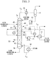
- CO 2 (carbon dioxide) recovery unit 1 according to one embodiment of the present invention will be explained with reference to the drawings.
- the CO 2 recovery unit 1 recovers carbon dioxide (CO 2 ) that is generated when fossil fuel is burned at a thermal power plant etc.
- the CO 2 recovery unit 1 allows amine compound solution (hereinafter, referred to as "absorbing liquid") to contact with combustion exhaust gas 60 discharged from a boiler or a gas turbine (not shown) to eliminate CO 2 included in the combustion exhaust gas 60, and stores CO 2 without discharging it to the ambient air.
- the CO 2 recovery unit 1 includes an absorbing tower 4 that allows the exhaust gas 60 with the absorbing liquid and a regeneration tower 7 that heats the absorbing liquid that absorbed CO 2 to eliminate CO 2 while regenerating the absorbing liquid.
- the regenerated absorbing liquid is delivered to the absorbing tower 4 and reused.
- the exhaust gas 60 including CO 2 discharged from the boiler or the gas turbine (not shown) placed in the thermal power plane etc. is delivered to a cooling tower 2 by a blower (not shown).
- the exhaust gas 60 supplied to the cooling tower 2 is cooled by circulation cooling water 61.
- the circulation cooling water 61 used to cool the exhaust gas 60 passes through a cooler 32 to be delivered to the cooling tower 2 again by a pump 31, and is sprayed in the tower. Additionally, in the cooler 32, cooling water 62 to cool the circulation cooling water 61 which is supplied to the cooling tower 2 is used.
- the exhaust gas 60 including the cooled CO 2 is supplied to a lower portion of the absorbing tower 4 via an exhaust gas line 3.
- the absorbing liquid is supplied from an upper portion of the absorbing tower 4 to a lower packing layer 20.
- the absorbing liquid is countercurrently contacted with the exhaust gas 60 while it passes through the packing layer 20.
- CO 2 in the exhaust gas 60 is absorbed in the absorbing liquid and CO 2 is eliminated from the exhaust gas 60.
- the exhaust gas 60 in which CO 2 is eliminated is called as purged gas 50.
- This purged gas 50 in which CO 2 is eliminated is discharged from a tower top portion 4a of the absorbing tower 4.
- the absorbing liquid Since CO 2 is absorbed in the absorbing liquid, the absorbing liquid produces heat and the liquid temperature is increased, so that the purged gas 50 can include water vapor etc.
- the water vapor in the purged gas 50 is condensed by cooling when it is countercurrently contacted with cooling water on an upper packing layer 20 of the absorbing tower 4.
- a mist eliminator 21 is provided above the packing layer 20 to collect mist in the purged gas 50.
- a cooler 22 and a pump 23 that circulates a part of the condensed water between the cooler 22 and the absorbing tower 4 are provided.
- the absorbing liquid that absorbed CO 2 in the absorbing tower 4 (hereinafter, referred to as "rich absorbing liquid”) is stored in the tower bottom portion 4b.
- the rich absorbing liquid is supplied to the regeneration tower 7 by a pump 6 via a liquid sending line L 1 connecting the tower bottom portion 4b of the absorbing tower 4 and an upper portion of the regeneration tower 7.
- the rich absorbing liquid is sprayed to a packing layer 41.
- a heat exchanger 9 that executes heat exchange between the rich absorbing liquid and the absorbing liquid in which CO 2 is eliminated in the regeneration tower 7 (hereinafter, referred to as "lean absorbing liquid”) is provided.
- the rich absorbing liquid flowing in the liquid sending line L 1 is heated, and the lean absorbing liquid flowing in the liquid sending line L 2 is cooled.
- the rich absorbing liquid is countercurrently contacted with hot steam during it passes through the packing layers 41, 42, and CO 2 is discharged by endothermic reaction.
- the absorbing liquid reaches the tower bottom portion 7b of the regeneration tower 7, most CO 2 is eliminated, and the absorbing liquid is regenerated as the lean absorbing liquid.
- the regenerated lean absorbing liquid is pumped by a pump 8 via the liquid sending line L 2 , and cooled while passing through the heat exchanger 9 and the cooler 5. Because of this, the lean absorbing liquid is fully cooled to the temperature that is suitable for CO 2 absorption in the absorbing tower 4. Thereafter, the lean absorbing liquid is supplied above the lower packing layer 20 of the absorbing tower 4 again to be reused.
- a CO 2 discharge line L 3 connects a tower top portion 7a of the regeneration tower 7 and a gas-liquid separator 11.
- the CO 2 discharged from the absorbing liquid in the regeneration tower 7 passes through the CO 2 discharge line L 3 , and after it is fully cooled via a cooler 15 using cooling water 62, it is sent to the gas-liquid separator 11.
- the CO 2 to be sent to the gas-liquid separator 11 includes water, and is separated into CO 2 and condensed water in the gas-liquid separator 11.
- the CO 2 from which water is separated is supplied to a CO 2 compression device (not shown). After that, the recovered CO 2 is compressed by the CO 2 compression device to become highpressure CO 2 .
- the condensed water collected in the gas-liquid separator 11 is refluxed to an upper portion of the regeneration tower 7 by a pump 12.
- the refluxed condensed water cools a condensation portion 43 provided in the regeneration tower 7. This prevents the discharge of the absorbing liquid etc. from the regeneration tower 7.
- a circulation line L 4 that circulates the lean absorbing liquid to the outside of the tower is provided, and a reboiler 30 is provided on the circulation line L 4 .
- the reboiler 30 heats the lean absorbing liquid by hot stream supplied by a stream pipe 33.
- a part of the absorbing liquid of the tower bottom portion 7b is supplied to the reboiler 30 via the circulation line L 4 , and after it is heated by heat exchange with hot steam, it is refluxed to the regeneration tower 7.
- CO 2 is discharged from the absorbing liquid of the tower bottom portion 7b.
- the packing layers 41, 42 are indirectly heated, which encourages the discharge of CO 2 from the absorbing liquid.
- a portion in which the absorbing liquid is heated and regenerated is divided into an upper regeneration portion 51 and a lower regeneration portion 52.
- the upper regeneration portion 51 includes a liquid dispersion portion 44, the packing layer 41 and a tray portion 45.
- the liquid dispersion portion 44 is provided above the packing layer 41, and supplies the rich absorbing liquid to the packing layer 41.
- the tray portion 45 is provided below the packing layer 41, and is constituted by, for example, a chimney tray and a seal pan.
- the rich absorbing liquid introduced from the liquid dispersion portion 44 of the upper regeneration portion 51 contacts with hot steam ascending from below while it flows down in the packing layer 41, and discharges CO 2 by endothermic reaction.
- the absorbing liquid that discharged CO 2 drops on the chimney tray of the tray portion 45, and is collected in the seal pan to be stored.
- the absorbing liquid stored in the seal pan of the tray portion 45 is supplied to a supply line L 5 .
- the lower regeneration portion 52 includes a liquid dispersion portion 46, the packing layer 42 and a tray portion 47.
- the liquid dispersion portion 46 is provided above the packing layer 42 and supplies the absorbing liquid introduced from the supply line L 5 to the packing layer 42.
- the tray portion 47 is provided below the packing layer 42, and is constituted by, for example, a chimney tray and a seal pan.
- the semi-lean absorbing liquid introduced from the liquid dispersion portion 46 of the lower regeneration portion 52 contacts with hot steam ascending from below while it flows down in the packing layer 42, and discharges CO 2 by endothermic reaction.
- the absorbing liquid that discharged CO 2 drops on the chimney tray of the tray portion 47 and collected on the seal pan to be stored.
- a part of the lean absorbing liquid stored on the seal pan of the tray portion 47 is supplied to the circulation line L 4 described above.
- the lean absorbing liquid supplied to the circulation line L 4 is heated by the reboiler 30, and introduced below the tray portion 47 of the lower regeneration portion 52 of the regeneration tower 7 to be stored in the tower bottom portion 7b of the regeneration tower 7.
- the absorbing liquid generates steam by heating, and the generated steam passes through the chimney trays of the tray portions 47, 45 and ascends in the regeneration tower 7.
- the supply line L 5 has one end connected to the tray portion 45 of the upper regeneration portion 51 and the other end connected to the liquid dispersion portion 46 of the lower regeneration portion 52.
- a heat exchanger 53 is provided on the supply line L 5 .
- fluid as a heat source is supplied, and heat exchange is executed between the fluid as a heat source and the absorbing liquid flowing in the supply line L 5 .
- the absorbing liquid flowing in the supply line L 5 is heated.
- the fluid as a heat source passing through the heat exchanger 53 the lean absorbing liquid, the steam condensed water, the exhaust gas, CO 2 and the like in the CO 2 recovery unit 1 can be listed.
- the supply line L 5 is semi-closed space which is closed other than a connecting portion with the tray portion 45 of the upper regeneration portion 51 and the liquid dispersion portion 46 of the lower regeneration portion 52.
- the liquid dispersion portion 46 of the lower regeneration portion 52 is positioned lower than the connecting portion with the tray portion 45 of the upper regeneration portion 51.
- piping of the supply line L 5 or the heat exchanger 53 partially includes a portion disposed higher than the liquid level of the absorbing liquid stored in the seal pan of the tray portion 45. That is, the hydraulic head difference caused by pressure loss in piping and the heat exchanger 53 relative to the liquid dispersion portion 46 of the lower regeneration portion 52 is equal to or larger than the height difference between the tray portion 45 and the liquid dispersion portion 46.
- a portion heated by the heat exchanger 53 is maintained at a higher temperature than that on the side of the regeneration tower 7.
- the absorbing liquid stored in the seal pan of the tray portion 45 of the upper regeneration portion 51 is supplied to the supply line L 5 and heated in the heat exchanger 53.
- CO 2 becomes partially gaseous when the temperature is increased in the heat exchanger 53. Consequently, the heated absorbing liquid has the smaller density compared to the pre-heating state before passing through the heat exchanger 53, and when the absorbing liquid exits the heat exchanger 53, it ascends to a higher position than the heat exchanger 53 in the supply line L 5 .
- the absorbing liquid is supplied to the liquid dispersion portion 46 of the lower regeneration portion 52.
- the absorbing liquid is heated in the heat exchanger 53 and CO 2 in the absorbing liquid becomes partially gaseous by the heating, which generates density difference between on the upstream side and the downstream side of the heat exchanger 53. Accordingly, even when there exists a higher portion than an extraction position of the upper regeneration portion 51 of the regeneration tower 7 in the piping or the heat exchanger 53 of the supply line L 5 , the supply line L 5 can supply the absorbing liquid to a higher portion without using the pump and it can introduce the absorbing liquid to the liquid dispersion portion 46 of the lower regeneration portion 52 of the regeneration tower 7.
- a pump 71 that increases the pressure of the absorbing liquid or a flow rate adjustment valve 73 that adjusts the flow rate of the absorbing liquid whose pressure is increased is unnecessary, which reduces the cost of equipment and the electric energy caused by the power.
- the reason of the delivery of CO 2 without any power is that CO 2 of the absorbing liquid becomes partially gaseous due to heating by the heat exchanger 53 to generate density difference between the absorbing liquid before the heat exchanger 53 and that after the heat exchanger 53, whereby a thermosiphon effect can be obtained. Accordingly, in this embodiment, when the absorbing liquid is supplied from the tray portion 45 of the upper regeneration portion 51 to the liquid dispersion portion 46 of the lower regeneration portion 52 via the heat exchanger 53, the absorbing liquid is supplied without providing the pump 71.
- the absorbing liquid to be delivered in the supply line L 5 includes gaseous CO 2 , so that when a pocket-shaped expansive bent pipe or a swivel joint is formed on the pipe line in the height direction, gas could be accumulated.
- the pipe line is formed not to include a section where gas accumulates. For example, by forming a pocket-shaped pipe line in the horizontal direction or by applying the configuration that absorbs expansion of the piping without forming the pocket-shaped pipe line or forming the pipe line in which absorption of the expansion of the piping is unnecessary, gas accumulation in the piping can be prevented. As a result, the absorbing liquid cannot be blocked by the accumulated gas, and is smoothly introduced from the tray portion 45 to the liquid dispersion portion 46.
- the regeneration portion can be divided into three parts of an upper regeneration portion, a middle regeneration portion and a lower regeneration portion, or it can be divided into four parts or more. Even in this case, the supply line L 5 can be placed between vertically adjacent regeneration portions.
Landscapes
- Chemical & Material Sciences (AREA)
- Engineering & Computer Science (AREA)
- Analytical Chemistry (AREA)
- General Chemical & Material Sciences (AREA)
- Oil, Petroleum & Natural Gas (AREA)
- Chemical Kinetics & Catalysis (AREA)
- Environmental & Geological Engineering (AREA)
- Health & Medical Sciences (AREA)
- Biomedical Technology (AREA)
- Gas Separation By Absorption (AREA)
- Treating Waste Gases (AREA)
Claims (4)
- CO2 Rückgewinnungseinheit, umfassend:einen Absorptionsturm (4), der es der Absorptionsflüssigkeit ermöglicht, CO2 im Abgas zu absorbieren; undeinen Regenerationsturm (7), der es der Absorptionsflüssigkeit, die CO2 in dem Absorptionsturm absorbiert hat, ermöglicht, CO2 abzugeben,wobei die Absorptionsflüssigkeit, die CO2 in dem Regenerationsturm (7) abgegeben hat, in dem Absorptionsturm (4) wiederverwendet wird,wobei der Regenerationsturm (7) beinhaltet:einen ersten Regenerationsabschnitt (51) mit einer ersten Ablageeinheit (45), welche die Absorptionsflüssigkeit speichert;einen zweiten Regenerationsabschnitt (52), der unterhalb des ersten Regenerationsabschnitts (51) vorgesehen ist und einen Flüssigkeitsverteilungsabschnitt (46), der die Absorptionsflüssigkeit zuführt, und eine zweite Ablageeinheit (47) aufweist, welche die Absorptionsflüssigkeit speichert; undein erstes Zuleitungsrohr (L5), das die erste Ablageeinheit (45) und den Flüssigkeitsverteilungsabschnitt verbindet, um die in der ersten Ablageeinheit (45) gespeicherte Absorptionsflüssigkeit dem Flüssigkeitsverteilungsabschnitt (46) zuzuführen,dadurch gekennzeichnet, dass das erste Zuleitungsrohr (L5) einen Heizabschnitt (53) beinhaltet, der dazu eingerichtet ist, eine Thermosiphonwirkung zu erzielen durch Erwärmen der Absorptionsflüssigkeit und durch teilweises Verdampfen der Absorptionsflüssigkeit, so dass das erste Zuleitungsrohr (L5) die Absorptionsflüssigkeit unter Verwendung einer Dichtedifferenz zwischen der Absorptionsflüssigkeit, die vor dem Heizabschnitt (53) fließt, und der Absorptionsflüssigkeit, die nach dem Heizabschnitt (53) fließt, als eine Antriebskraft zirkulieren lassen kann,wobei das erste Zuleitungsrohr (L5) keine Pumpvorrichtung, die die Absorptionsflüssigkeit pumpt, oder keinen Steuerabschnitt, der eine Durchflussrate der Absorptionsflüssigkeit steuert, aufweist,der Flüssigkeitsverteilungsabschnitt (46) tiefer als ein Verbindungsabschnitt angeordnet ist, mit welchem das erste Zuleitungsrohr (L5) und die erste Ablageeinheit (45) verbunden sind, unddas erste Zuleitungsrohr (L5) oder der Heizabschnitt (53) teilweise einen Abschnitt beinhaltet, der höher als eine Extraktionsposition der Absorptionsflüssigkeit von dem ersten Regenerationsabschnitt (51) angeordnet ist und das erste Zuleitungsrohr (L5) einen weiteren Abschnitt aufweist, in dem die Absorptionsflüssigkeit fließt, nachdem sie den Heizabschnitt (53) verlassen hat, wobei der weitere Abschnitt höher als der Heizabschnitt (53) angeordnet ist.
- CO2 Rückgewinnungseinheit nach Anspruch 1, wobei ein taschenförmig aufgeweitetes gebogenes Rohr oder ein Drehgelenk nicht an dem ersten Zuleitungsrohr (L5) in Höhenrichtung ausgebildet ist.
- CO2 Rückgewinnungseinheit nach Anspruch 1, weiterhin umfassend:ein zweites Zuleitungsrohr (L4), das die zweite Ablageeinheit (47) und einen Teil (7b) unterhalb der zweiten Ablageeinheit (47) verbindet, um die in der zweiten Ablageeinheit (47) gespeicherte Absorptionsflüssigkeit dem Teil unterhalb der zweiten Ablageeinheit (47) zuzuführen; undeinen Verdampfer (30), der an dem zweiten Zuleitungsrohr (L4) vorgesehen ist und dazu ausgelegt ist, durch Erwärmen der Absorptionsflüssigkeit Dampf zu erzeugen.
- Verfahren zur Verwendung der CO2 Rückgewinnungseinheit nach Anspruch 1, wobei eine Druckdifferenz, bewirkt durch Druckverlust in dem ersten Zuleitungsrohr (L5) und dem Heizabschnitt relativ zu dem Flüssigkeitsverteilungsabschnitt des zweiten Regenerationsabschnitts (52) gleich oder größer ist als ein Höhenunterschied zwischen der ersten Ablageeinheit (45) und dem Flüssigkeitsverteilungsabschnitt.
Applications Claiming Priority (2)
| Application Number | Priority Date | Filing Date | Title |
|---|---|---|---|
| US13/623,448 US9233337B2 (en) | 2012-09-20 | 2012-09-20 | CO2 recovery device |
| PCT/JP2013/075197 WO2014046146A1 (ja) | 2012-09-20 | 2013-09-18 | Co2回収装置 |
Publications (3)
| Publication Number | Publication Date |
|---|---|
| EP2910293A1 EP2910293A1 (de) | 2015-08-26 |
| EP2910293A4 EP2910293A4 (de) | 2016-05-18 |
| EP2910293B1 true EP2910293B1 (de) | 2020-11-04 |
Family
ID=50273104
Family Applications (1)
| Application Number | Title | Priority Date | Filing Date |
|---|---|---|---|
| EP13838785.7A Active EP2910293B1 (de) | 2012-09-20 | 2013-09-18 | Co2-rückgewinnungsvorrichtung |
Country Status (6)
| Country | Link |
|---|---|
| US (1) | US9233337B2 (de) |
| EP (1) | EP2910293B1 (de) |
| JP (1) | JP5968450B2 (de) |
| AU (1) | AU2013319045B2 (de) |
| CA (1) | CA2885342C (de) |
| WO (1) | WO2014046146A1 (de) |
Families Citing this family (6)
| Publication number | Priority date | Publication date | Assignee | Title |
|---|---|---|---|---|
| US10005019B2 (en) * | 2014-02-21 | 2018-06-26 | Sharp Kabushiki Kaisha | Carbon dioxide concentration-controlling device and electronic apparatus |
| CN106659962B (zh) | 2014-08-20 | 2019-06-21 | 夏普株式会社 | 二氧化碳浓度控制系统和二氧化碳浓度控制装置 |
| JP6639918B2 (ja) | 2016-01-14 | 2020-02-05 | 三菱重工エンジニアリング株式会社 | Co2回収装置及び回収方法 |
| KR102189717B1 (ko) * | 2018-12-05 | 2020-12-14 | 한국과학기술연구원 | 흡수탑과 탈거탑이 하나의 탑으로 구성된 가스 포집장치 및 이를 이용한 가스 포집방법 |
| US20250032973A1 (en) * | 2023-07-26 | 2025-01-30 | Mitsubishi Heavy Industries, Ltd. | Co2 recovery device |
| JP2025069890A (ja) * | 2023-10-18 | 2025-05-01 | 三菱重工業株式会社 | 再生塔、制御装置及び制御方法 |
Citations (1)
| Publication number | Priority date | Publication date | Assignee | Title |
|---|---|---|---|---|
| US20110120315A1 (en) * | 2004-03-15 | 2011-05-26 | Mitsubishi Heavy Industries, Ltd. | Co2 recovery system and method |
Family Cites Families (6)
| Publication number | Priority date | Publication date | Assignee | Title |
|---|---|---|---|---|
| JP4745682B2 (ja) * | 2005-02-23 | 2011-08-10 | 関西電力株式会社 | Co2回収装置および方法 |
| JP5021917B2 (ja) * | 2005-09-01 | 2012-09-12 | 三菱重工業株式会社 | Co2回収装置及び方法 |
| JP4773865B2 (ja) | 2006-04-13 | 2011-09-14 | 三菱重工業株式会社 | Co2回収装置及びco2回収方法 |
| JP5495520B2 (ja) * | 2008-07-23 | 2014-05-21 | 三菱重工業株式会社 | 排ガス中の二酸化炭素回収装置 |
| JP5737844B2 (ja) | 2010-02-08 | 2015-06-17 | 三菱重工業株式会社 | Co2回収装置の熱回収設備および熱回収方法 |
| JP5351816B2 (ja) | 2010-04-08 | 2013-11-27 | 三菱重工業株式会社 | 排ガス中の二酸化炭素回収装置及び方法 |
-
2012
- 2012-09-20 US US13/623,448 patent/US9233337B2/en active Active
-
2013
- 2013-09-18 AU AU2013319045A patent/AU2013319045B2/en active Active
- 2013-09-18 WO PCT/JP2013/075197 patent/WO2014046146A1/ja not_active Ceased
- 2013-09-18 JP JP2014536886A patent/JP5968450B2/ja active Active
- 2013-09-18 CA CA2885342A patent/CA2885342C/en active Active
- 2013-09-18 EP EP13838785.7A patent/EP2910293B1/de active Active
Patent Citations (1)
| Publication number | Priority date | Publication date | Assignee | Title |
|---|---|---|---|---|
| US20110120315A1 (en) * | 2004-03-15 | 2011-05-26 | Mitsubishi Heavy Industries, Ltd. | Co2 recovery system and method |
Also Published As
| Publication number | Publication date |
|---|---|
| EP2910293A4 (de) | 2016-05-18 |
| EP2910293A1 (de) | 2015-08-26 |
| US20140076165A1 (en) | 2014-03-20 |
| JPWO2014046146A1 (ja) | 2016-08-18 |
| AU2013319045A1 (en) | 2015-04-02 |
| CA2885342C (en) | 2017-07-18 |
| JP5968450B2 (ja) | 2016-08-10 |
| AU2013319045B2 (en) | 2016-05-12 |
| CA2885342A1 (en) | 2014-03-27 |
| US9233337B2 (en) | 2016-01-12 |
| WO2014046146A1 (ja) | 2014-03-27 |
Similar Documents
| Publication | Publication Date | Title |
|---|---|---|
| EP2910293B1 (de) | Co2-rückgewinnungsvorrichtung | |
| US9662607B2 (en) | CO2 recovery unit and CO2 recovery method | |
| EP2722097B1 (de) | System zur verarbeitung von verbrennungsabgasen und verfahren zur verarbeitung von verbrennungsabgasen | |
| US9492783B2 (en) | Carbon dioxide gas recovery device | |
| US9400106B2 (en) | CO2 recovery system and recovery method for moisture containing CO2 gas | |
| EP2899462B1 (de) | Wärmerückgewinnungssystem und wärmerückgewinnungsverfahren | |
| US8961665B2 (en) | Exhaust gas treatment system | |
| EP2910292B1 (de) | System zur dampfbereitstellung und ein solches system umfassende co2-rückgewinnungsanlagen | |
| US20140102096A1 (en) | Carbon-dioxide recovery system |
Legal Events
| Date | Code | Title | Description |
|---|---|---|---|
| PUAI | Public reference made under article 153(3) epc to a published international application that has entered the european phase |
Free format text: ORIGINAL CODE: 0009012 |
|
| 17P | Request for examination filed |
Effective date: 20150318 |
|
| AK | Designated contracting states |
Kind code of ref document: A1 Designated state(s): AL AT BE BG CH CY CZ DE DK EE ES FI FR GB GR HR HU IE IS IT LI LT LU LV MC MK MT NL NO PL PT RO RS SE SI SK SM TR |
|
| AX | Request for extension of the european patent |
Extension state: BA ME |
|
| DAX | Request for extension of the european patent (deleted) | ||
| RA4 | Supplementary search report drawn up and despatched (corrected) |
Effective date: 20160420 |
|
| RIC1 | Information provided on ipc code assigned before grant |
Ipc: B01D 53/62 20060101AFI20160412BHEP Ipc: B01D 53/14 20060101ALI20160412BHEP |
|
| STAA | Information on the status of an ep patent application or granted ep patent |
Free format text: STATUS: EXAMINATION IS IN PROGRESS |
|
| 17Q | First examination report despatched |
Effective date: 20170530 |
|
| RAP1 | Party data changed (applicant data changed or rights of an application transferred) |
Owner name: MITSUBISHI HEAVY INDUSTRIES ENGINEERING, LTD. |
|
| GRAP | Despatch of communication of intention to grant a patent |
Free format text: ORIGINAL CODE: EPIDOSNIGR1 |
|
| STAA | Information on the status of an ep patent application or granted ep patent |
Free format text: STATUS: GRANT OF PATENT IS INTENDED |
|
| INTG | Intention to grant announced |
Effective date: 20191015 |
|
| GRAS | Grant fee paid |
Free format text: ORIGINAL CODE: EPIDOSNIGR3 |
|
| GRAJ | Information related to disapproval of communication of intention to grant by the applicant or resumption of examination proceedings by the epo deleted |
Free format text: ORIGINAL CODE: EPIDOSDIGR1 |
|
| GRAL | Information related to payment of fee for publishing/printing deleted |
Free format text: ORIGINAL CODE: EPIDOSDIGR3 |
|
| STAA | Information on the status of an ep patent application or granted ep patent |
Free format text: STATUS: EXAMINATION IS IN PROGRESS |
|
| INTC | Intention to grant announced (deleted) | ||
| GRAP | Despatch of communication of intention to grant a patent |
Free format text: ORIGINAL CODE: EPIDOSNIGR1 |
|
| STAA | Information on the status of an ep patent application or granted ep patent |
Free format text: STATUS: GRANT OF PATENT IS INTENDED |
|
| INTG | Intention to grant announced |
Effective date: 20200715 |
|
| GRAS | Grant fee paid |
Free format text: ORIGINAL CODE: EPIDOSNIGR3 |
|
| GRAA | (expected) grant |
Free format text: ORIGINAL CODE: 0009210 |
|
| STAA | Information on the status of an ep patent application or granted ep patent |
Free format text: STATUS: THE PATENT HAS BEEN GRANTED |
|
| AK | Designated contracting states |
Kind code of ref document: B1 Designated state(s): AL AT BE BG CH CY CZ DE DK EE ES FI FR GB GR HR HU IE IS IT LI LT LU LV MC MK MT NL NO PL PT RO RS SE SI SK SM TR |
|
| REG | Reference to a national code |
Ref country code: GB Ref legal event code: FG4D |
|
| REG | Reference to a national code |
Ref country code: CH Ref legal event code: EP |
|
| REG | Reference to a national code |
Ref country code: AT Ref legal event code: REF Ref document number: 1330079 Country of ref document: AT Kind code of ref document: T Effective date: 20201115 |
|
| REG | Reference to a national code |
Ref country code: DE Ref legal event code: R096 Ref document number: 602013073851 Country of ref document: DE |
|
| REG | Reference to a national code |
Ref country code: IE Ref legal event code: FG4D |
|
| REG | Reference to a national code |
Ref country code: NL Ref legal event code: FP |
|
| REG | Reference to a national code |
Ref country code: AT Ref legal event code: MK05 Ref document number: 1330079 Country of ref document: AT Kind code of ref document: T Effective date: 20201104 |
|
| REG | Reference to a national code |
Ref country code: NO Ref legal event code: T2 Effective date: 20201104 |
|
| PG25 | Lapsed in a contracting state [announced via postgrant information from national office to epo] |
Ref country code: RS Free format text: LAPSE BECAUSE OF FAILURE TO SUBMIT A TRANSLATION OF THE DESCRIPTION OR TO PAY THE FEE WITHIN THE PRESCRIBED TIME-LIMIT Effective date: 20201104 Ref country code: FI Free format text: LAPSE BECAUSE OF FAILURE TO SUBMIT A TRANSLATION OF THE DESCRIPTION OR TO PAY THE FEE WITHIN THE PRESCRIBED TIME-LIMIT Effective date: 20201104 Ref country code: PT Free format text: LAPSE BECAUSE OF FAILURE TO SUBMIT A TRANSLATION OF THE DESCRIPTION OR TO PAY THE FEE WITHIN THE PRESCRIBED TIME-LIMIT Effective date: 20210304 Ref country code: GR Free format text: LAPSE BECAUSE OF FAILURE TO SUBMIT A TRANSLATION OF THE DESCRIPTION OR TO PAY THE FEE WITHIN THE PRESCRIBED TIME-LIMIT Effective date: 20210205 |
|
| PG25 | Lapsed in a contracting state [announced via postgrant information from national office to epo] |
Ref country code: ES Free format text: LAPSE BECAUSE OF FAILURE TO SUBMIT A TRANSLATION OF THE DESCRIPTION OR TO PAY THE FEE WITHIN THE PRESCRIBED TIME-LIMIT Effective date: 20201104 Ref country code: AT Free format text: LAPSE BECAUSE OF FAILURE TO SUBMIT A TRANSLATION OF THE DESCRIPTION OR TO PAY THE FEE WITHIN THE PRESCRIBED TIME-LIMIT Effective date: 20201104 Ref country code: BG Free format text: LAPSE BECAUSE OF FAILURE TO SUBMIT A TRANSLATION OF THE DESCRIPTION OR TO PAY THE FEE WITHIN THE PRESCRIBED TIME-LIMIT Effective date: 20210204 Ref country code: LV Free format text: LAPSE BECAUSE OF FAILURE TO SUBMIT A TRANSLATION OF THE DESCRIPTION OR TO PAY THE FEE WITHIN THE PRESCRIBED TIME-LIMIT Effective date: 20201104 Ref country code: IS Free format text: LAPSE BECAUSE OF FAILURE TO SUBMIT A TRANSLATION OF THE DESCRIPTION OR TO PAY THE FEE WITHIN THE PRESCRIBED TIME-LIMIT Effective date: 20210304 Ref country code: PL Free format text: LAPSE BECAUSE OF FAILURE TO SUBMIT A TRANSLATION OF THE DESCRIPTION OR TO PAY THE FEE WITHIN THE PRESCRIBED TIME-LIMIT Effective date: 20201104 Ref country code: SE Free format text: LAPSE BECAUSE OF FAILURE TO SUBMIT A TRANSLATION OF THE DESCRIPTION OR TO PAY THE FEE WITHIN THE PRESCRIBED TIME-LIMIT Effective date: 20201104 |
|
| REG | Reference to a national code |
Ref country code: LT Ref legal event code: MG9D |
|
| PG25 | Lapsed in a contracting state [announced via postgrant information from national office to epo] |
Ref country code: HR Free format text: LAPSE BECAUSE OF FAILURE TO SUBMIT A TRANSLATION OF THE DESCRIPTION OR TO PAY THE FEE WITHIN THE PRESCRIBED TIME-LIMIT Effective date: 20201104 |
|
| PG25 | Lapsed in a contracting state [announced via postgrant information from national office to epo] |
Ref country code: CZ Free format text: LAPSE BECAUSE OF FAILURE TO SUBMIT A TRANSLATION OF THE DESCRIPTION OR TO PAY THE FEE WITHIN THE PRESCRIBED TIME-LIMIT Effective date: 20201104 Ref country code: EE Free format text: LAPSE BECAUSE OF FAILURE TO SUBMIT A TRANSLATION OF THE DESCRIPTION OR TO PAY THE FEE WITHIN THE PRESCRIBED TIME-LIMIT Effective date: 20201104 Ref country code: SM Free format text: LAPSE BECAUSE OF FAILURE TO SUBMIT A TRANSLATION OF THE DESCRIPTION OR TO PAY THE FEE WITHIN THE PRESCRIBED TIME-LIMIT Effective date: 20201104 Ref country code: RO Free format text: LAPSE BECAUSE OF FAILURE TO SUBMIT A TRANSLATION OF THE DESCRIPTION OR TO PAY THE FEE WITHIN THE PRESCRIBED TIME-LIMIT Effective date: 20201104 Ref country code: SK Free format text: LAPSE BECAUSE OF FAILURE TO SUBMIT A TRANSLATION OF THE DESCRIPTION OR TO PAY THE FEE WITHIN THE PRESCRIBED TIME-LIMIT Effective date: 20201104 Ref country code: LT Free format text: LAPSE BECAUSE OF FAILURE TO SUBMIT A TRANSLATION OF THE DESCRIPTION OR TO PAY THE FEE WITHIN THE PRESCRIBED TIME-LIMIT Effective date: 20201104 |
|
| REG | Reference to a national code |
Ref country code: DE Ref legal event code: R097 Ref document number: 602013073851 Country of ref document: DE |
|
| PG25 | Lapsed in a contracting state [announced via postgrant information from national office to epo] |
Ref country code: DK Free format text: LAPSE BECAUSE OF FAILURE TO SUBMIT A TRANSLATION OF THE DESCRIPTION OR TO PAY THE FEE WITHIN THE PRESCRIBED TIME-LIMIT Effective date: 20201104 |
|
| PLBE | No opposition filed within time limit |
Free format text: ORIGINAL CODE: 0009261 |
|
| STAA | Information on the status of an ep patent application or granted ep patent |
Free format text: STATUS: NO OPPOSITION FILED WITHIN TIME LIMIT |
|
| 26N | No opposition filed |
Effective date: 20210805 |
|
| PG25 | Lapsed in a contracting state [announced via postgrant information from national office to epo] |
Ref country code: IT Free format text: LAPSE BECAUSE OF FAILURE TO SUBMIT A TRANSLATION OF THE DESCRIPTION OR TO PAY THE FEE WITHIN THE PRESCRIBED TIME-LIMIT Effective date: 20201104 Ref country code: AL Free format text: LAPSE BECAUSE OF FAILURE TO SUBMIT A TRANSLATION OF THE DESCRIPTION OR TO PAY THE FEE WITHIN THE PRESCRIBED TIME-LIMIT Effective date: 20201104 |
|
| PG25 | Lapsed in a contracting state [announced via postgrant information from national office to epo] |
Ref country code: SI Free format text: LAPSE BECAUSE OF FAILURE TO SUBMIT A TRANSLATION OF THE DESCRIPTION OR TO PAY THE FEE WITHIN THE PRESCRIBED TIME-LIMIT Effective date: 20201104 |
|
| REG | Reference to a national code |
Ref country code: CH Ref legal event code: PL |
|
| PG25 | Lapsed in a contracting state [announced via postgrant information from national office to epo] |
Ref country code: IS Free format text: LAPSE BECAUSE OF FAILURE TO SUBMIT A TRANSLATION OF THE DESCRIPTION OR TO PAY THE FEE WITHIN THE PRESCRIBED TIME-LIMIT Effective date: 20210304 Ref country code: MC Free format text: LAPSE BECAUSE OF FAILURE TO SUBMIT A TRANSLATION OF THE DESCRIPTION OR TO PAY THE FEE WITHIN THE PRESCRIBED TIME-LIMIT Effective date: 20201104 |
|
| PG25 | Lapsed in a contracting state [announced via postgrant information from national office to epo] |
Ref country code: LU Free format text: LAPSE BECAUSE OF NON-PAYMENT OF DUE FEES Effective date: 20210918 Ref country code: IE Free format text: LAPSE BECAUSE OF NON-PAYMENT OF DUE FEES Effective date: 20210918 |
|
| PG25 | Lapsed in a contracting state [announced via postgrant information from national office to epo] |
Ref country code: LI Free format text: LAPSE BECAUSE OF NON-PAYMENT OF DUE FEES Effective date: 20210930 Ref country code: CH Free format text: LAPSE BECAUSE OF NON-PAYMENT OF DUE FEES Effective date: 20210930 |
|
| PG25 | Lapsed in a contracting state [announced via postgrant information from national office to epo] |
Ref country code: HU Free format text: LAPSE BECAUSE OF FAILURE TO SUBMIT A TRANSLATION OF THE DESCRIPTION OR TO PAY THE FEE WITHIN THE PRESCRIBED TIME-LIMIT; INVALID AB INITIO Effective date: 20130918 |
|
| P01 | Opt-out of the competence of the unified patent court (upc) registered |
Effective date: 20230522 |
|
| PG25 | Lapsed in a contracting state [announced via postgrant information from national office to epo] |
Ref country code: CY Free format text: LAPSE BECAUSE OF FAILURE TO SUBMIT A TRANSLATION OF THE DESCRIPTION OR TO PAY THE FEE WITHIN THE PRESCRIBED TIME-LIMIT Effective date: 20201104 |
|
| REG | Reference to a national code |
Ref country code: DE Ref legal event code: R081 Ref document number: 602013073851 Country of ref document: DE Owner name: MITSUBISHI HEAVY INDUSTRIES, LTD., JP Free format text: FORMER OWNER: MITSUBISHI HEAVY INDUSTRIES ENGINEERING, LTD., YOKOHAMA-SHI, KANAGAWA, JP |
|
| REG | Reference to a national code |
Ref country code: DE Ref legal event code: R081 Ref document number: 602013073851 Country of ref document: DE Owner name: MITSUBISHI HEAVY INDUSTRIES, LTD., JP Free format text: FORMER OWNER: MHI ENGINEERING, LTD., YOKOHAMA-SHI, KANAGAWA, JP |
|
| REG | Reference to a national code |
Ref country code: NL Ref legal event code: PD Owner name: MITSUBISHI HEAVY INDUSTRIES, LTD.; JP Free format text: DETAILS ASSIGNMENT: CHANGE OF OWNER(S), ASSIGNMENT; FORMER OWNER NAME: MHI ENGINEERING, LTD. Effective date: 20231206 Ref country code: NL Ref legal event code: HC Owner name: MHI ENGINEERING, LTD.; JP Free format text: DETAILS ASSIGNMENT: CHANGE OF OWNER(S), CHANGE OF OWNER(S) NAME; FORMER OWNER NAME: MITSUBISHI HEAVY INDUSTRIES ENGINEERING, LTD. Effective date: 20231206 |
|
| REG | Reference to a national code |
Ref country code: BE Ref legal event code: PD Owner name: MITSUBISHI HEAVY INDUSTRIES, LTD.; JP Free format text: DETAILS ASSIGNMENT: CHANGE OF OWNER(S), ASSIGNMENT; FORMER OWNER NAME: MHI ENGINEERING, LTD. Effective date: 20231208 Ref country code: BE Ref legal event code: HC Owner name: MHI ENGINEERING, LTD.; JP Free format text: DETAILS ASSIGNMENT: CHANGE OF OWNER(S), CHANGE OF OWNER(S) NAME; FORMER OWNER NAME: MITSUBISHI HEAVY INDUSTRIES ENGINEERING, LTD. Effective date: 20231208 |
|
| PG25 | Lapsed in a contracting state [announced via postgrant information from national office to epo] |
Ref country code: MK Free format text: LAPSE BECAUSE OF FAILURE TO SUBMIT A TRANSLATION OF THE DESCRIPTION OR TO PAY THE FEE WITHIN THE PRESCRIBED TIME-LIMIT Effective date: 20201104 |
|
| REG | Reference to a national code |
Ref country code: GB Ref legal event code: 732E Free format text: REGISTERED BETWEEN 20240404 AND 20240410 |
|
| PG25 | Lapsed in a contracting state [announced via postgrant information from national office to epo] |
Ref country code: MT Free format text: LAPSE BECAUSE OF FAILURE TO SUBMIT A TRANSLATION OF THE DESCRIPTION OR TO PAY THE FEE WITHIN THE PRESCRIBED TIME-LIMIT Effective date: 20201104 |
|
| PGFP | Annual fee paid to national office [announced via postgrant information from national office to epo] |
Ref country code: NL Payment date: 20250814 Year of fee payment: 13 |
|
| PGFP | Annual fee paid to national office [announced via postgrant information from national office to epo] |
Ref country code: DE Payment date: 20250730 Year of fee payment: 13 |
|
| PGFP | Annual fee paid to national office [announced via postgrant information from national office to epo] |
Ref country code: NO Payment date: 20250909 Year of fee payment: 13 |
|
| PGFP | Annual fee paid to national office [announced via postgrant information from national office to epo] |
Ref country code: GB Payment date: 20250731 Year of fee payment: 13 Ref country code: BE Payment date: 20250818 Year of fee payment: 13 |
|
| PGFP | Annual fee paid to national office [announced via postgrant information from national office to epo] |
Ref country code: FR Payment date: 20250808 Year of fee payment: 13 |
|
| PG25 | Lapsed in a contracting state [announced via postgrant information from national office to epo] |
Ref country code: TR Free format text: LAPSE BECAUSE OF FAILURE TO SUBMIT A TRANSLATION OF THE DESCRIPTION OR TO PAY THE FEE WITHIN THE PRESCRIBED TIME-LIMIT Effective date: 20201104 |