EP2910292A1 - Steam providing system and co2 recovery facilities provided with same - Google Patents
Steam providing system and co2 recovery facilities provided with same Download PDFInfo
- Publication number
- EP2910292A1 EP2910292A1 EP13838237.9A EP13838237A EP2910292A1 EP 2910292 A1 EP2910292 A1 EP 2910292A1 EP 13838237 A EP13838237 A EP 13838237A EP 2910292 A1 EP2910292 A1 EP 2910292A1
- Authority
- EP
- European Patent Office
- Prior art keywords
- condensed water
- steam
- water drum
- reboiler
- drain
- Prior art date
- Legal status (The legal status is an assumption and is not a legal conclusion. Google has not performed a legal analysis and makes no representation as to the accuracy of the status listed.)
- Granted
Links
Images

Classifications
-
- B—PERFORMING OPERATIONS; TRANSPORTING
- B01—PHYSICAL OR CHEMICAL PROCESSES OR APPARATUS IN GENERAL
- B01D—SEPARATION
- B01D53/00—Separation of gases or vapours; Recovering vapours of volatile solvents from gases; Chemical or biological purification of waste gases, e.g. engine exhaust gases, smoke, fumes, flue gases, aerosols
- B01D53/14—Separation of gases or vapours; Recovering vapours of volatile solvents from gases; Chemical or biological purification of waste gases, e.g. engine exhaust gases, smoke, fumes, flue gases, aerosols by absorption
- B01D53/1425—Regeneration of liquid absorbents
-
- B—PERFORMING OPERATIONS; TRANSPORTING
- B01—PHYSICAL OR CHEMICAL PROCESSES OR APPARATUS IN GENERAL
- B01D—SEPARATION
- B01D53/00—Separation of gases or vapours; Recovering vapours of volatile solvents from gases; Chemical or biological purification of waste gases, e.g. engine exhaust gases, smoke, fumes, flue gases, aerosols
- B01D53/14—Separation of gases or vapours; Recovering vapours of volatile solvents from gases; Chemical or biological purification of waste gases, e.g. engine exhaust gases, smoke, fumes, flue gases, aerosols by absorption
- B01D53/1412—Controlling the absorption process
-
- B—PERFORMING OPERATIONS; TRANSPORTING
- B01—PHYSICAL OR CHEMICAL PROCESSES OR APPARATUS IN GENERAL
- B01D—SEPARATION
- B01D53/00—Separation of gases or vapours; Recovering vapours of volatile solvents from gases; Chemical or biological purification of waste gases, e.g. engine exhaust gases, smoke, fumes, flue gases, aerosols
- B01D53/14—Separation of gases or vapours; Recovering vapours of volatile solvents from gases; Chemical or biological purification of waste gases, e.g. engine exhaust gases, smoke, fumes, flue gases, aerosols by absorption
- B01D53/1456—Removing acid components
- B01D53/1475—Removing carbon dioxide
-
- B—PERFORMING OPERATIONS; TRANSPORTING
- B01—PHYSICAL OR CHEMICAL PROCESSES OR APPARATUS IN GENERAL
- B01D—SEPARATION
- B01D53/00—Separation of gases or vapours; Recovering vapours of volatile solvents from gases; Chemical or biological purification of waste gases, e.g. engine exhaust gases, smoke, fumes, flue gases, aerosols
- B01D53/34—Chemical or biological purification of waste gases
- B01D53/46—Removing components of defined structure
- B01D53/62—Carbon oxides
-
- B—PERFORMING OPERATIONS; TRANSPORTING
- B01—PHYSICAL OR CHEMICAL PROCESSES OR APPARATUS IN GENERAL
- B01D—SEPARATION
- B01D53/00—Separation of gases or vapours; Recovering vapours of volatile solvents from gases; Chemical or biological purification of waste gases, e.g. engine exhaust gases, smoke, fumes, flue gases, aerosols
- B01D53/34—Chemical or biological purification of waste gases
- B01D53/74—General processes for purification of waste gases; Apparatus or devices specially adapted therefor
- B01D53/77—Liquid phase processes
- B01D53/78—Liquid phase processes with gas-liquid contact
-
- F—MECHANICAL ENGINEERING; LIGHTING; HEATING; WEAPONS; BLASTING
- F22—STEAM GENERATION
- F22B—METHODS OF STEAM GENERATION; STEAM BOILERS
- F22B37/00—Component parts or details of steam boilers
- F22B37/008—Adaptations for flue-gas purification in steam generators
-
- F—MECHANICAL ENGINEERING; LIGHTING; HEATING; WEAPONS; BLASTING
- F23—COMBUSTION APPARATUS; COMBUSTION PROCESSES
- F23J—REMOVAL OR TREATMENT OF COMBUSTION PRODUCTS OR COMBUSTION RESIDUES; FLUES
- F23J15/00—Arrangements of devices for treating smoke or fumes
- F23J15/02—Arrangements of devices for treating smoke or fumes of purifiers, e.g. for removing noxious material
-
- B—PERFORMING OPERATIONS; TRANSPORTING
- B01—PHYSICAL OR CHEMICAL PROCESSES OR APPARATUS IN GENERAL
- B01D—SEPARATION
- B01D2252/00—Absorbents, i.e. solvents and liquid materials for gas absorption
- B01D2252/20—Organic absorbents
- B01D2252/204—Amines
-
- B—PERFORMING OPERATIONS; TRANSPORTING
- B01—PHYSICAL OR CHEMICAL PROCESSES OR APPARATUS IN GENERAL
- B01D—SEPARATION
- B01D2252/00—Absorbents, i.e. solvents and liquid materials for gas absorption
- B01D2252/20—Organic absorbents
- B01D2252/204—Amines
- B01D2252/20478—Alkanolamines
-
- B—PERFORMING OPERATIONS; TRANSPORTING
- B01—PHYSICAL OR CHEMICAL PROCESSES OR APPARATUS IN GENERAL
- B01D—SEPARATION
- B01D2257/00—Components to be removed
- B01D2257/50—Carbon oxides
- B01D2257/504—Carbon dioxide
-
- B—PERFORMING OPERATIONS; TRANSPORTING
- B01—PHYSICAL OR CHEMICAL PROCESSES OR APPARATUS IN GENERAL
- B01D—SEPARATION
- B01D2258/00—Sources of waste gases
- B01D2258/02—Other waste gases
- B01D2258/0283—Flue gases
-
- B—PERFORMING OPERATIONS; TRANSPORTING
- B01—PHYSICAL OR CHEMICAL PROCESSES OR APPARATUS IN GENERAL
- B01D—SEPARATION
- B01D3/00—Distillation or related exchange processes in which liquids are contacted with gaseous media, e.g. stripping
- B01D3/14—Fractional distillation or use of a fractionation or rectification column
- B01D3/32—Other features of fractionating columns ; Constructional details of fractionating columns not provided for in groups B01D3/16 - B01D3/30
- B01D3/322—Reboiler specifications
-
- F—MECHANICAL ENGINEERING; LIGHTING; HEATING; WEAPONS; BLASTING
- F23—COMBUSTION APPARATUS; COMBUSTION PROCESSES
- F23J—REMOVAL OR TREATMENT OF COMBUSTION PRODUCTS OR COMBUSTION RESIDUES; FLUES
- F23J2215/00—Preventing emissions
- F23J2215/50—Carbon dioxide
-
- F—MECHANICAL ENGINEERING; LIGHTING; HEATING; WEAPONS; BLASTING
- F23—COMBUSTION APPARATUS; COMBUSTION PROCESSES
- F23J—REMOVAL OR TREATMENT OF COMBUSTION PRODUCTS OR COMBUSTION RESIDUES; FLUES
- F23J2219/00—Treatment devices
- F23J2219/40—Sorption with wet devices, e.g. scrubbers
-
- Y—GENERAL TAGGING OF NEW TECHNOLOGICAL DEVELOPMENTS; GENERAL TAGGING OF CROSS-SECTIONAL TECHNOLOGIES SPANNING OVER SEVERAL SECTIONS OF THE IPC; TECHNICAL SUBJECTS COVERED BY FORMER USPC CROSS-REFERENCE ART COLLECTIONS [XRACs] AND DIGESTS
- Y02—TECHNOLOGIES OR APPLICATIONS FOR MITIGATION OR ADAPTATION AGAINST CLIMATE CHANGE
- Y02A—TECHNOLOGIES FOR ADAPTATION TO CLIMATE CHANGE
- Y02A50/00—TECHNOLOGIES FOR ADAPTATION TO CLIMATE CHANGE in human health protection, e.g. against extreme weather
- Y02A50/20—Air quality improvement or preservation, e.g. vehicle emission control or emission reduction by using catalytic converters
-
- Y—GENERAL TAGGING OF NEW TECHNOLOGICAL DEVELOPMENTS; GENERAL TAGGING OF CROSS-SECTIONAL TECHNOLOGIES SPANNING OVER SEVERAL SECTIONS OF THE IPC; TECHNICAL SUBJECTS COVERED BY FORMER USPC CROSS-REFERENCE ART COLLECTIONS [XRACs] AND DIGESTS
- Y02—TECHNOLOGIES OR APPLICATIONS FOR MITIGATION OR ADAPTATION AGAINST CLIMATE CHANGE
- Y02C—CAPTURE, STORAGE, SEQUESTRATION OR DISPOSAL OF GREENHOUSE GASES [GHG]
- Y02C20/00—Capture or disposal of greenhouse gases
- Y02C20/40—Capture or disposal of greenhouse gases of CO2
-
- Y—GENERAL TAGGING OF NEW TECHNOLOGICAL DEVELOPMENTS; GENERAL TAGGING OF CROSS-SECTIONAL TECHNOLOGIES SPANNING OVER SEVERAL SECTIONS OF THE IPC; TECHNICAL SUBJECTS COVERED BY FORMER USPC CROSS-REFERENCE ART COLLECTIONS [XRACs] AND DIGESTS
- Y02—TECHNOLOGIES OR APPLICATIONS FOR MITIGATION OR ADAPTATION AGAINST CLIMATE CHANGE
- Y02E—REDUCTION OF GREENHOUSE GAS [GHG] EMISSIONS, RELATED TO ENERGY GENERATION, TRANSMISSION OR DISTRIBUTION
- Y02E20/00—Combustion technologies with mitigation potential
- Y02E20/32—Direct CO2 mitigation
Definitions
- the present invention relates to a steam supply system which is preferably used in CO 2 recovery unit in exhaust gas discharged from an industrial facility, for example, and the CO 2 recovery unit including the same.
- CO 2 carbon dioxide
- a step of eliminating and recovering CO 2 from combustion exhaust gas using the CO 2 absorbing liquid as described above a step of contacting the combustion exhaust gas with the CO 2 absorbing liquid in an absorbing tower and a step of heating the absorbing liquid that absorbed CO 2 in a regeneration tower to release CO 2 as well as regenerate the absorbing liquid for circulation to the absorbing tower to be reused have been adopted.
- Patent Literature 1 discloses that, in a regeneration tower, MEA (monoethanolamine) solution is regenerated due to heating by a regenerative heater (reboiler) and cooled by a heat exchanger to be returned to a CO 2 elimination tower.
- MEA monoethanolamine
- Fig. 5 shows a schematic configuration showing a reference example of a steam supply system.
- Absorbing liquid (not shown) of a regeneration tower (not shown) is reheated by a circulation route L 4 that circulates the absorbing liquid to the outside of the tower and steam to be provided to a heat exchanger tube 130a of a reboiler 130 provided to a tower bottom portion of the regeneration tower.
- the steam supply tube 2 is connected, and steam is supplied to the heat exchanger tube 130a in the reboiler.
- the steam that applied heat to the absorbing liquid by the heat exchanger tube 130a is sent to the condensed water drum 5 and subjected to gas-liquid separation in the condensed water drum.
- condensed water 6 flows from the bottom of the condensed water drum 5 through a drain extraction tube 7, and delivered by a pump 8 via a steam drain tube 9.
- differential pressure between the condensed water drum and the heat exchanger tube provided in the reboiler is small. This causes a problem that the condensed water in the heat exchanger tube provided in the reboiler is difficult to flow to the condensed water drum, whereby performance of the reboiler and the liquid level of the condensed water drum become unstable.
- the present invention is made considering such circumstances, and an object of the present invention is to provide a steam supply system that reheats CO 2 absorbing liquid without lowering performance of the reboiler by appropriately controlling the inner pressure of the condensed water drum.
- a steam supply system comprises: a reboiler that raises a temperature of absorbing liquid contacted with exhaust gas discharged from a boiler to absorb CO 2 in the exhaust gas and heated to eliminate CO 2 , the reboiler including: a heat exchanger tube to which steam for heating is supplied; and a condensed water drum that recovers condensed water of the steam introduced from the heat exchanger tube as steam drain, wherein the condensed water drum is provided with decompression unit that lowers pressure in the condensed water drum.
- decompression unit that lowers the pressure in the condensed water drum is provided.
- the pressure difference occurs between the reboiler and the condensed water drum, and the condensed water easily flows from the reboiler on the high-pressure side to the condensed water drum on the low-pressure side.
- the decompression unit is cooling unit that cools condensed water in the condensed water drum.
- Cooling unit that cools the condensed water in the condensed water drum is provided.
- this cooling unit for example, a part of the condensed water extracted from the condensed water drum is cooled and returned to the condensed water drum again. By doing this, the temperature of the condensed water drum is lowered and the pressure in the condensed water drum can be lowered.
- the cooling unit includes: a drain circulation route branched from a steam drain piping that discharges the steam drain from the condensed water drum, the drain circulation route returning the steam drain to the condensed water drum; and a cooler that cools the steam drain branched to the drain circulation route side.
- Steam drain flows in the drain circulation route branched from the steam drain piping that discharges the steam drain from the condensed water drum and passes through the cooler to be returned to the condensed water drum.
- saturation temperature and saturation pressure can be lowered. This lowers the pressure in the condensed water drum.
- the cooling unit includes: a cooler provided on a steam drain piping that discharges the steam drain from the condensed water drum; and a steam drain circulation route branched from the downstream side of the cooler, the steam drain circulation route returning the steam drain to the condensed water drum.
- a steam drain circulation route branched from the downstream side of the cooler is provided to return the steam drain to the condensed water drum. By doing this, providing the cooler to the branched circulation route is unnecessary.
- the cooling unit includes a cooler provided on a reboiler exit piping that connects the reboiler and the condensed water drum.
- a cooler provided on a reboiler exit piping that connects the reboiler and the condensed water drum is provided. This lowers the temperature of steam drain to be recovered by the condensed water drum. Since the steam drain cooled by the cooler is supplied to the condensed water drum, saturation temperature and saturation pressure can be lowered by cooling the condensed water drum. Accordingly, the inner pressure of the condensed water drum can be lowered.
- the decompression unit includes a vent tube that discharges gas phase in the condensed water drum.
- vent tube By providing a vent tube with the condensed water drum, when the inner pressure of the condensed water drum becomes a predetermined value or more for example, the vent tube can be opened to discharge gas phase of the condensed water drum to lower the inner pressure.
- the steam supply system includes: a pressure measuring portion that obtains a pressure difference between an inner pressure of the condensed water drum and a steam pressure to be supplied to the reboiler; and control unit that controls the decompression unit so as to adjust the pressure difference obtained in the pressure measuring portion to a desired value.
- a signal is transmitted from the pressure measuring portion to obtain the pressure difference between the inner pressure of the condensed water drum and the steam pressure to be supplied to the reboiler to the control unit that controls the decompression unit.
- the control unit that received the signal can regulate the flow rate of a cooling medium flowing in the cooler since the degree of opening of the control unit is determined from the pressure difference between the steam pressure to be supplied to the reboiler and the inner pressure of the condensed water drum.
- CO 2 recovery unit includes: an absorbing tower that contacts CO 2 in exhaust gas with the absorbing liquid to absorb CO 2 ; and a regeneration tower that discharges CO 2 absorbed in the absorbing tower from the absorbing liquid, wherein the regeneration tower includes a reboiler having the steam supply system described above.
- a decompression unit that lowers the pressure of the condensed water drum to provide the pressure difference between the pressure in the heat exchanger tube of the reboiler and the inner pressure of the condensed water drum provided in the CO 2 recovery unit is provided.
- the condensed water generated in the heat exchanger tube stably flows to the condensed water drum to prevent the condensed water from retaining in the heat exchanger tube. Accordingly, the reboiler can be operated stably, so that CO 2 absorbing liquid circulating in the regeneration tower can be surely reheated.
- Fig. 6 shows a basic configuration of a CO 2 recovery apparatus according to this embodiment.
- exhaust gas 100 including CO 2 discharged from an industrial facility such as a boiler and a gas turbine is supplied to a cooling tower 102 by a not shown blower.
- the exhaust gas 100 supplied to the cooling tower 102 is cooled by cooling water 101.
- the cooling water 101 used to cool the exhaust gas 100 passes through a cooler 132 to be supplied to the cooling tower 102 again, and is sprayed in the tower. Additionally, in the cooler 132, cooling water 101a that cools the cooling water 101 to be supplied to the cooling tower 102 is used.
- the exhaust gas 100 including the cooled CO 2 is supplied from a lower portion of an absorbing tower 104 via an exhaust gas line 103.
- the absorbing liquid 113 is supplied from an upper portion of the absorbing tower 104 and sprayed to the lower portion.
- alkanolamine-based CO 2 absorbing liquid 113 amine solution
- CO 2 in the exhaust gas 100 is absorbed in the CO 2 absorbing liquid 113, and CO 2 is eliminated from the exhaust gas 100 discharged from the industrial facility. From a tower top portion 104a of the absorbing tower 104, cleaned gas 150 in which CO 2 is eliminated is discharged.
- the absorbing liquid 113 produces heat and raises its temperature by absorbing CO 2 , so that the cleaned gas 150 can include water vapor etc.
- the water vapor in the cleaned gas 150 is condensed by being cooled through countercurrent contact with cooled water on the packing layer 120 at the upper portion of the absorbing tower 104.
- a mist eliminator 121 is placed above the packing layer 120 to capture mist in the cleaned gas 150.
- a cooler 122 and a pump 123 that circulates a part of the condensed water between the cooler 122 and the absorbing tower 104 are placed.
- the absorbing liquid 113 that absorbed CO 2 in the absorbing tower 104 is retained in a tower bottom portion 104b, and supplied by a pump 106 from a liquid sending line L 1 that connects the tower bottom portion 104b of the absorbing tower 104 and an upper portion of a regeneration tower 107 to the regeneration tower 107 to be sprayed to a packing 140.
- a heat exchanger 109 that executes heat exchange between rich solution 113 (absorbing liquid that absorbed CO 2 ) and lean solution 114 (absorbing liquid in which CO 2 is eliminated) is placed.
- the rich solution 113 is heated and the lean solution 114 is cooled.
- CO 2 In the CO 2 absorbing liquid 113 that absorbed CO 2 (rich solution), CO 2 is discharged due to endothermic reaction by countercurrent contact during passage through the packing 140 in the regeneration tower 107. Most CO 2 is eliminated until the CO 2 absorbing liquid reaches a tower bottom portion 107b of the regeneration tower 107, and the CO 2 absorbing liquid is regenerated as lean solution 114.
- the regenerated lean solution 114 is supplied to the absorbing tower 104 again by a pump 108 via a lean solution cooling apparatus 105 as CO 2 absorbing liquid (anime solution), and reused.
- the lean solution 114 which is regenerated by discharging CO 2 in the regeneration tower 107 is refluxed to the absorbing tower 104 by the pump 108 through the liquid sending line L 2 that connects the tower bottom portion 107b of the regeneration tower 107 and the upper portion of the absorbing tower 104, and during that, in the heat exchanger 109, it is subjected to heat exchange with the absorbing liquid 113 to be supplied from the absorbing tower 104 to the regeneration tower 107 to be cooled, and further, fully cooled to the temperature which is suitable for absorbing CO 2 by the water-cooling type cooler 105.
- the reference symbol L 3 denotes a CO 2 discharge line connected to the tower top portion 107a of the regeneration tower 107.
- CO 2 discharged from the CO 2 absorbing liquid 113 in the regeneration tower 107 by the line L 3 is fully cooled via a cooler 115 using cooling water 101 to be sent to a gas-liquid separator 111.
- the CO 2 sent to the gas-liquid separator 111 is separated from condensed water 110 which is accompanied after the elimination of CO 2 .
- the separated CO 2 is sent to a not shown CO 2 compression apparatus. After that, the recovered carbon dioxide (CO 2 ) is compressed by the CO 2 compression apparatus to obtain high-pressure CO 2 .
- the condensed water 110 separated in the gas-liquid separator 111 is refluxed to the upper portion of the regeneration tower 107 by a pump 112.
- the refluxed condensed water 110 cools a condensing portion 141 to prevent discharge of an absorbing agent etc.
- the absorbing liquid 113 including CO 2 in the absorbing tower 104 is supplied to the upper portion of the regeneration tower 107, passes through the packing 140 to be retained in the tower bottom portion 107b.
- a reboiler 130 is provided to the tower bottom portion 107b of the regeneration tower 107.
- a circulation route L 4 that circulates the absorbing liquid 113 to the outside of the tower and a heat exchanger tube 130a that heats the absorbing liquid 113 are provided.
- a part of the absorbing liquid 113 of the tower bottom portion 107b is supplied to the reboiler 130 through the circulation route L 4 , and refluxed in the tower after it is heated due to heat exchange with high-temperature steam. Due to this heating, CO 2 is discharged from the absorbing liquid 113 in the tower bottom portion 107b, and CO 2 is also discharged from the absorbing liquid 113 during gas-liquid contact on the packing 140 which is indirectly heated.
- Fig. 1 shows a configuration of a part surrounding the reboiler 130 provided to the tower bottom portion 107b of the regeneration tower 107 shown in Fig. 6 .
- a number of heat exchanger tubes 130a connected to a steam supply tube 2 are placed to contact with absorbing liquid flowing in the circulation route L 4 .
- Each heat exchanger tube 130a is connected to a steam discharge tube 4 connected to a condensed water drum 5.
- a measuring portion 10b for pressure measuring is provided to the condensed water drum 5. Moreover, to the steam supply tube 2, a measuring portion 10a for pressure measuring is provided. Based on the pressure obtained from these measuring portions 10a, 10b, the pressure difference can be obtained at a control portion 10. Further, to the condensed water drum 5, a vent tube 13 (decompression unit) is placed, and the vent tube 13 includes a control valve 12 that regulates the flow rate of the vent tube 13. Via this vent tube 13, gas phase (steam) in the condensed water drum 5 is discharged to the outside (for example, the ambient air).
- a steam drain extraction tube 7 is connected, which is connected to an intake portion of the pump 8.
- a discharge portion of the pump 8 is connected to a steam drain tube 9, and a heater 15 is provided to the steam drain tube 9.
- a plurality of heat exchanger tubes are placed to contact with steam drain introduced from the steam drain tube 9.
- the lean solution 114 see Fig. 6
- discharging CO 2 is used as a heating medium 14 flowing in the heat exchanger tube.
- a part of the absorbing liquid 113 of the tower bottom portion 107b is supplied to the reboiler 130 through the circulation route L 4 , and heated due to heat exchange with the heat exchanger tube 130a in which steam supplied from the steam supply tube 2 flows to be refluxed to the regeneration tower 107.
- the steam after heat exchange is supplied to the condensed water drum 5 and subjected to gas-liquid separation in the condensed water drum 5.
- the inner pressure of the condensed water drum 5 is measured.
- the control portion 10 is controlled such that the measuring portions 10a and 10b that measure in-tube pressure of the steam supply tube 2 provide the pressure difference.
- the control portion 10 transmits a signal 11 to the control valve 12 provided on the vent tube 13 when the pressure in the measuring portion 10b is raised so that the pressure difference between the measuring portions 10a and 10b exceeds a predetermined value to be close to pressure equalization.
- the degree of opening of the control valve 12 is determined based on the pressure difference.
- the condensed water 6 subjected to gas-liquid separation by the condensed water drum 5 is supplied to the pump 8 via the steam drain extraction tube 7.
- the condensed water 6 supplied to the pump 8 is sent passing through the steam drain tube 9.
- the condensed water 6 is indirectly heated by a heating medium 14 (for example, lean solution) flowing in the heat exchanger tube penetrating through the heater 15 provided on the steam drain tube 9.
- a heating medium 14 for example, lean solution
- the vent tube 13 is provided as decompression unit that lowers the pressure of the condensed water drum 5.
- the vent tube 13 the pressure difference is generated between the reboiler 130 and the condensed water drum 5, and the condensed water 6 easily flows from the reboiler 130 on the high-pressure side to the condensed water drum 5 on the low-pressure side. This makes performance of the reboiler 130 and the liquid level of the condensed water drum 5 stable.
- control valve 12 provided on the vent tube 13 is automatically opened and closed. This eliminates handle operation of the control valve 12 for regulating the pressure of the condensed water drum 5. Accordingly, the time or labor spent by an operator etc. for operating the valve can be lowered.
- the condensed water drum 5 is decompressed by cooling unit that cools the condensed water 6 in the condensed water drum 5. Accordingly, the same components as those in the first embodiment are applied the same reference numerals, and their explanation is omitted.
- a drain circulation route 20 branched from a steam drain piping 9 that discharges the condensed water 6 from the condensed water drum 5 to return the condensed water 6 to the condensed water drum 5 is provided.
- This drain circulation route 20 is provided with a cooler 21 (cooling unit) that cools the condensed water 6.
- the condensed water 6 discharged from the condensed water drum 5 flows in the steam drain piping 9 by the pump 8.
- the drain circulation route 20 that returns the condensed water 6 to the condensed water drum 5 is branched from the steam drain piping 9, a part of the condensed water 6 is indirectly cooled by a cooling medium 22 (for example, rich solution) flowing in a plurality of heat exchanger tubes provided in the cooler 21 when it passes through the cooler 21 to be supplied to the condensed water drum 5.
- a cooling medium 22 for example, rich solution
- the cooling medium 22 flowing in the cooler 21 is controlled by the control portion 10.
- the control portion 10 obtains the pressure difference between the measuring portion 10b that measures the inner pressure of the condensed water drum 5 and the measuring portion 10a that measures the steam pressure to be supplied to the reboiler 130 and controls the control valve 12a such that the obtained pressure difference is a desired value.
- the control portion 10 transmits a signal 11 to the control valve 12a provided on the drain circulation route 20. In the control valve 12a that received the signal 11, the degree of opening of the control valve 12a is determined based on the pressure difference, and the amount of condensed water 6 cooled by the cooler 21 to be returned to the condensed water drum 5 is controlled.
- the condensed water 6 flows in the drain circulation route 20 branched from the steam drain piping 9 that discharges the condensed water 6 from the condensed water drum 5, passes through the cooler 21 to be cooled, and is returned to the condensed water drum 5.
- saturation temperature and saturation pressure can be lowered. This lowers the pressure of the condensed water drum 5.
- Fig. 3 shows a schematic configuration showing a modification of the steam supply system according to the second embodiment of the present invention.
- the cooler 21 provided on the steam drain piping 9 that discharges the condensed water 6 from the condensed water drum 5 and the steam drain circulation route 20 branched from the downstream side of the cooler 21 to return the condensed water 6 to the condensed water drum 5 are provided.
- the steam drain circulation route 20 branched from the downstream side of the cooler 21 to return the condensed water 6 to the condensed water drum 5 is provided. Because of this, providing the cooler to the branched circulation route 20 is unnecessary.
- the present embodiment decompresses the condensed water drum 5 by cooling unit that cools the condensed water 6 in the condensed water drum 5, instead of the decompression unit of condensed water drum 5 shown in the first and second embodiments. Accordingly, the same components as in the first and second embodiments are applied the same reference numerals and their explanation is omitted.
- the cooler 21 (cooling unit) is provided on an exit piping 4 of the reboiler 130 that connects the reboiler 130 and the condensed water drum 5.
- Fluid in which the steam flowing in the heat exchanger tube 130a of the reboiler 130 and the condensed water 6 are mixed flows in the exit piping 4 to be cooled by the cooler 21 provided on the exit piping 4.
- the cooled fluid in which the steam and the condensed water 6 are mixed is supplied to the condensed water drum 5.
- the cooling medium 22 (for example, rich solution) flowing in the plurality of heat exchanger tubes provided in the cooler 21 is controlled by the control portion 10.
- the control portion 10 obtains the pressure difference between the measuring portion 10b that measures the inner pressure of the condensed water drum 5 and the measuring portion 10a that measures the steam pressure to be supplied to the reboiler 130, and controls the control valve 12b such that the pressure difference obtained at the measuring portions 10a and 10b is a desired value.
- the temperature of the condensed water 6 recovered by the condensed water drum 5 can be lowered.
- mixed fluid of the steam cooled by the cooler 21 and the condensed water 6 is supplied.
- saturation temperature and saturation pressure can be lowered. Accordingly, the inner pressure of the condensed water drum 5 can be lowered.
- cooler 21 is provided on the exit piping 4 in this embodiment, not limited to this, it may be provided on the steam drain extraction piping 7. Further, a recycle line may be formed to circulate the condensed water 6 by providing another extraction port separated from the steam drain extraction piping 7 of the condensed water drum 5, and the cooler 21 may be placed on the recycle line.
Landscapes
- Engineering & Computer Science (AREA)
- Chemical & Material Sciences (AREA)
- Analytical Chemistry (AREA)
- General Chemical & Material Sciences (AREA)
- Oil, Petroleum & Natural Gas (AREA)
- Chemical Kinetics & Catalysis (AREA)
- Environmental & Geological Engineering (AREA)
- Mechanical Engineering (AREA)
- General Engineering & Computer Science (AREA)
- Health & Medical Sciences (AREA)
- Biomedical Technology (AREA)
- Thermal Sciences (AREA)
- Physics & Mathematics (AREA)
- Gas Separation By Absorption (AREA)
- Treating Waste Gases (AREA)
- Carbon And Carbon Compounds (AREA)
Abstract
Description
- The present invention relates to a steam supply system which is preferably used in CO2 recovery unit in exhaust gas discharged from an industrial facility, for example, and the CO2 recovery unit including the same.
- From industrial facilities such as thermal power generation equipment, a large amount of carbon dioxide (hereinafter, referred to as CO2) is discharged due to combustion of fossil fuel such as coal and fuel oil. Emission limitation of CO2 has been considered from the viewpoint of prevention of global warming, and as one measure, there has been the CO2 separation and recovery technology.
- For industrial facilities such as a thermal power plant that uses a large amount of fossil fuel, a method of eliminating and recovering CO2 in combustion exhaust gas by contacting combustion exhaust gas of a boiler with amine based CO2 absorbing liquid, for example, and a method of storing the recovered CO2 without discharging it to the ambient air have been known.
- Moreover, as a step of eliminating and recovering CO2 from combustion exhaust gas using the CO2 absorbing liquid as described above, a step of contacting the combustion exhaust gas with the CO2 absorbing liquid in an absorbing tower and a step of heating the absorbing liquid that absorbed CO2 in a regeneration tower to release CO2 as well as regenerate the absorbing liquid for circulation to the absorbing tower to be reused have been adopted.
- Patent Literature 1 discloses that, in a regeneration tower, MEA (monoethanolamine) solution is regenerated due to heating by a regenerative heater (reboiler) and cooled by a heat exchanger to be returned to a CO2 elimination tower.
- Japanese Unexamined Patent Application, Publication No.
H5-184866 - However, in a reboiler provided in such CO2 recovery apparatus, since the pressure difference between the reboiler and a condensed water drum is small, condensed water in a heat exchanger tube provided in the reboiler is difficult to flow to the condensed water drum, whereby performance of the reboiler and the liquid level of the condensed water drum become unstable, which has been problematic.
-
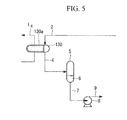
Fig. 5 shows a schematic configuration showing a reference example of a steam supply system. Absorbing liquid (not shown) of a regeneration tower (not shown) is reheated by a circulation route L4 that circulates the absorbing liquid to the outside of the tower and steam to be provided to aheat exchanger tube 130a of areboiler 130 provided to a tower bottom portion of the regeneration tower. To thereboiler 130, thesteam supply tube 2 is connected, and steam is supplied to theheat exchanger tube 130a in the reboiler. The steam that applied heat to the absorbing liquid by theheat exchanger tube 130a is sent to the condensedwater drum 5 and subjected to gas-liquid separation in the condensed water drum. Moreover, condensedwater 6 flows from the bottom of the condensedwater drum 5 through adrain extraction tube 7, and delivered by apump 8 via asteam drain tube 9. - In the steam supply system shown in
Fig. 5 , differential pressure between the condensed water drum and the heat exchanger tube provided in the reboiler is small. This causes a problem that the condensed water in the heat exchanger tube provided in the reboiler is difficult to flow to the condensed water drum, whereby performance of the reboiler and the liquid level of the condensed water drum become unstable. - In addition, since performance of the reboiler is lowered, there has been a problem that efficiency of discharging CO2 from the CO2 absorbing liquid that absorbed CO2 in the regeneration tower to regenerate the CO2 absorbing liquid is lowered.
- The present invention is made considering such circumstances, and an object of the present invention is to provide a steam supply system that reheats CO2 absorbing liquid without lowering performance of the reboiler by appropriately controlling the inner pressure of the condensed water drum.
- In order to solve the above problem, a steam supply system and CO2 recovery unit including the same according to the present invention apply the following means.
- A steam supply system according to a first aspect of the present invention comprises: a reboiler that raises a temperature of absorbing liquid contacted with exhaust gas discharged from a boiler to absorb CO2 in the exhaust gas and heated to eliminate CO2, the reboiler including: a heat exchanger tube to which steam for heating is supplied; and a condensed water drum that recovers condensed water of the steam introduced from the heat exchanger tube as steam drain, wherein the condensed water drum is provided with decompression unit that lowers pressure in the condensed water drum.
- For example, even when the pressure of the condensed water drum is raised to be close to the pressure of the heat exchanger tube of the reboiler, decompression unit that lowers the pressure in the condensed water drum is provided. By this decompression unit, the pressure difference occurs between the reboiler and the condensed water drum, and the condensed water easily flows from the reboiler on the high-pressure side to the condensed water drum on the low-pressure side. This makes performance of the reboiler and the liquid level of the condensed water drum stable. Since the performance of the reboiler is stable, heat can be stably applied to the CO2 absorbing liquid circulating in the regeneration tower. This ensures separation of CO2 in the CO2 absorbing liquid.
- Further, in the steam supply system according to a second aspect of the present invention, the decompression unit is cooling unit that cools condensed water in the condensed water drum.
- Cooling unit that cools the condensed water in the condensed water drum is provided. In this cooling unit, for example, a part of the condensed water extracted from the condensed water drum is cooled and returned to the condensed water drum again. By doing this, the temperature of the condensed water drum is lowered and the pressure in the condensed water drum can be lowered.
- Further, in the steam supply system according a third aspect of the present invention, the cooling unit includes: a drain circulation route branched from a steam drain piping that discharges the steam drain from the condensed water drum, the drain circulation route returning the steam drain to the condensed water drum; and a cooler that cools the steam drain branched to the drain circulation route side.
- Steam drain flows in the drain circulation route branched from the steam drain piping that discharges the steam drain from the condensed water drum and passes through the cooler to be returned to the condensed water drum. By returning the steam drain cooled by the cooler to the condensed water drum, saturation temperature and saturation pressure can be lowered. This lowers the pressure in the condensed water drum.
- Further, in the steam supply system according to a forth aspect of the present invention, the cooling unit includes: a cooler provided on a steam drain piping that discharges the steam drain from the condensed water drum; and a steam drain circulation route branched from the downstream side of the cooler, the steam drain circulation route returning the steam drain to the condensed water drum.
- A steam drain circulation route branched from the downstream side of the cooler is provided to return the steam drain to the condensed water drum. By doing this, providing the cooler to the branched circulation route is unnecessary.
- Further, in the steam supply system according to a fifth aspect of the present invention, the cooling unit includes a cooler provided on a reboiler exit piping that connects the reboiler and the condensed water drum.
- As cooling unit, a cooler provided on a reboiler exit piping that connects the reboiler and the condensed water drum is provided. This lowers the temperature of steam drain to be recovered by the condensed water drum. Since the steam drain cooled by the cooler is supplied to the condensed water drum, saturation temperature and saturation pressure can be lowered by cooling the condensed water drum. Accordingly, the inner pressure of the condensed water drum can be lowered.
- Further, in the steam supply system according to a sixth aspect of the present invention, the decompression unit includes a vent tube that discharges gas phase in the condensed water drum.
- By providing a vent tube with the condensed water drum, when the inner pressure of the condensed water drum becomes a predetermined value or more for example, the vent tube can be opened to discharge gas phase of the condensed water drum to lower the inner pressure.
- Further, the steam supply system according to a seventh aspect of the present invention includes: a pressure measuring portion that obtains a pressure difference between an inner pressure of the condensed water drum and a steam pressure to be supplied to the reboiler; and control unit that controls the decompression unit so as to adjust the pressure difference obtained in the pressure measuring portion to a desired value.
- A signal is transmitted from the pressure measuring portion to obtain the pressure difference between the inner pressure of the condensed water drum and the steam pressure to be supplied to the reboiler to the control unit that controls the decompression unit. The control unit that received the signal can regulate the flow rate of a cooling medium flowing in the cooler since the degree of opening of the control unit is determined from the pressure difference between the steam pressure to be supplied to the reboiler and the inner pressure of the condensed water drum.
- Further, CO2 recovery unit according to an eighth aspect of the present invention includes: an absorbing tower that contacts CO2 in exhaust gas with the absorbing liquid to absorb CO2; and a regeneration tower that discharges CO2 absorbed in the absorbing tower from the absorbing liquid, wherein the regeneration tower includes a reboiler having the steam supply system described above.
- Since performance of the reboiler is made stable due to the steam supply system, heat can be stably applied to the CO2 absorbing liquid circulating in the regeneration tower. This ensures separation of CO2 in the CO2 absorbing liquid, so that stable CO2 recovery can be achieved.
- According to the steam supply system and the CO2 recovery unit including the same according to the present invention, a decompression unit that lowers the pressure of the condensed water drum to provide the pressure difference between the pressure in the heat exchanger tube of the reboiler and the inner pressure of the condensed water drum provided in the CO2 recovery unit is provided. By doing this, the condensed water generated in the heat exchanger tube stably flows to the condensed water drum to prevent the condensed water from retaining in the heat exchanger tube. Accordingly, the reboiler can be operated stably, so that CO2 absorbing liquid circulating in the regeneration tower can be surely reheated.
-
- {
Fig. 1 }
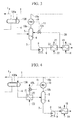
Fig. 1 is a schematic configuration diagram showing a steam supply system regarding a first embodiment according to the present invention. - {
Fig. 2 }
Fig. 2 is a schematic configuration diagram showing a steam supply system regarding a second embodiment according to the present invention. - {
Fig. 3 }
Fig. 3 is a schematic configuration diagram showing a modification of the steam supply system regarding the second embodiment according to the present invention. - {
Fig. 4 }
Fig. 4 is a schematic configuration diagram showing a steam supply system regarding a third embodiment of the present invention. - {
Fig. 5 }
Fig. 5 is a schematic configuration diagram showing a reference example of a steam supply system. - {
Fig. 6 }
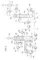
Fig. 6 is a schematic configuration diagram of a CO2 recovery apparatus to which the steam supply system according to the present invention is applied. - Hereinafter, embodiments of a steam supply system and CO2 recovery unit including the same according to the present invention will be explained with reference to the drawings.
- Hereinafter, a first embodiment of the present invention will be explained.
-
Fig. 6 shows a basic configuration of a CO2 recovery apparatus according to this embodiment. - As shown in
Fig. 6 , in the CO2 recovery apparatus,exhaust gas 100 including CO2 discharged from an industrial facility such as a boiler and a gas turbine is supplied to acooling tower 102 by a not shown blower. Theexhaust gas 100 supplied to thecooling tower 102 is cooled by coolingwater 101. The coolingwater 101 used to cool theexhaust gas 100, by apump 131, passes through a cooler 132 to be supplied to thecooling tower 102 again, and is sprayed in the tower. Additionally, in the cooler 132, coolingwater 101a that cools the coolingwater 101 to be supplied to thecooling tower 102 is used. - The
exhaust gas 100 including the cooled CO2 is supplied from a lower portion of an absorbingtower 104 via anexhaust gas line 103. The absorbingliquid 113 is supplied from an upper portion of the absorbingtower 104 and sprayed to the lower portion. In the absorbingtower 104, for example, alkanolamine-based CO2 absorbing liquid 113 (amine solution) is countercurrently contacted with theexhaust gas 100 while passing apacking 120. Because of this, CO2 in theexhaust gas 100 is absorbed in the CO2 absorbing liquid 113, and CO2 is eliminated from theexhaust gas 100 discharged from the industrial facility. From atower top portion 104a of the absorbingtower 104, cleanedgas 150 in which CO2 is eliminated is discharged. - The absorbing
liquid 113 produces heat and raises its temperature by absorbing CO2, so that the cleanedgas 150 can include water vapor etc. The water vapor in the cleanedgas 150 is condensed by being cooled through countercurrent contact with cooled water on thepacking layer 120 at the upper portion of the absorbingtower 104. Amist eliminator 121 is placed above thepacking layer 120 to capture mist in the cleanedgas 150. On the outside of the absorbingtower 104, a cooler 122 and apump 123 that circulates a part of the condensed water between the cooler 122 and the absorbingtower 104 are placed. - The absorbing liquid 113 that absorbed CO2 in the absorbing
tower 104 is retained in atower bottom portion 104b, and supplied by apump 106 from a liquid sending line L1 that connects thetower bottom portion 104b of the absorbingtower 104 and an upper portion of a regeneration tower 107 to the regeneration tower 107 to be sprayed to apacking 140. On an intersection of the liquid sending line L1 and a liquid sending line L2, aheat exchanger 109 that executes heat exchange between rich solution 113 (absorbing liquid that absorbed CO2) and lean solution 114 (absorbing liquid in which CO2 is eliminated) is placed. In theheat exchanger 109, therich solution 113 is heated and thelean solution 114 is cooled. - In the CO2 absorbing liquid 113 that absorbed CO2 (rich solution), CO2 is discharged due to endothermic reaction by countercurrent contact during passage through the packing 140 in the regeneration tower 107. Most CO2 is eliminated until the CO2 absorbing liquid reaches a
tower bottom portion 107b of the regeneration tower 107, and the CO2 absorbing liquid is regenerated aslean solution 114. The regeneratedlean solution 114 is supplied to the absorbingtower 104 again by apump 108 via a leansolution cooling apparatus 105 as CO2 absorbing liquid (anime solution), and reused. - The
lean solution 114 which is regenerated by discharging CO2 in the regeneration tower 107 is refluxed to the absorbingtower 104 by thepump 108 through the liquid sending line L2 that connects thetower bottom portion 107b of the regeneration tower 107 and the upper portion of the absorbingtower 104, and during that, in theheat exchanger 109, it is subjected to heat exchange with the absorbing liquid 113 to be supplied from the absorbingtower 104 to the regeneration tower 107 to be cooled, and further, fully cooled to the temperature which is suitable for absorbing CO2 by the water-coolingtype cooler 105. - The reference symbol L3 denotes a CO2 discharge line connected to the
tower top portion 107a of the regeneration tower 107. CO2 discharged from the CO2 absorbing liquid 113 in the regeneration tower 107 by the line L3 is fully cooled via a cooler 115 usingcooling water 101 to be sent to a gas-liquid separator 111. The CO2 sent to the gas-liquid separator 111 is separated fromcondensed water 110 which is accompanied after the elimination of CO2. The separated CO2 is sent to a not shown CO2 compression apparatus. After that, the recovered carbon dioxide (CO2) is compressed by the CO2 compression apparatus to obtain high-pressure CO2. Thecondensed water 110 separated in the gas-liquid separator 111 is refluxed to the upper portion of the regeneration tower 107 by apump 112. - The refluxed
condensed water 110 cools a condensing portion 141 to prevent discharge of an absorbing agent etc. - The absorbing liquid 113 including CO2 in the absorbing
tower 104 is supplied to the upper portion of the regeneration tower 107, passes through the packing 140 to be retained in thetower bottom portion 107b. Areboiler 130 is provided to thetower bottom portion 107b of the regeneration tower 107. Moreover, a circulation route L4 that circulates the absorbing liquid 113 to the outside of the tower and aheat exchanger tube 130a that heats the absorbingliquid 113 are provided. A part of the absorbingliquid 113 of thetower bottom portion 107b is supplied to thereboiler 130 through the circulation route L4, and refluxed in the tower after it is heated due to heat exchange with high-temperature steam. Due to this heating, CO2 is discharged from the absorbing liquid 113 in thetower bottom portion 107b, and CO2 is also discharged from the absorbing liquid 113 during gas-liquid contact on the packing 140 which is indirectly heated. -
Fig. 1 shows a configuration of a part surrounding thereboiler 130 provided to thetower bottom portion 107b of the regeneration tower 107 shown inFig. 6 . In thereboiler 130, a number ofheat exchanger tubes 130a connected to asteam supply tube 2 are placed to contact with absorbing liquid flowing in the circulation route L4. Eachheat exchanger tube 130a is connected to asteam discharge tube 4 connected to acondensed water drum 5. - To the
condensed water drum 5, a measuringportion 10b for pressure measuring is provided. Moreover, to thesteam supply tube 2, a measuringportion 10a for pressure measuring is provided. Based on the pressure obtained from these measuringportions control portion 10. Further, to thecondensed water drum 5, a vent tube 13 (decompression unit) is placed, and thevent tube 13 includes acontrol valve 12 that regulates the flow rate of thevent tube 13. Via thisvent tube 13, gas phase (steam) in thecondensed water drum 5 is discharged to the outside (for example, the ambient air). - To the bottom portion of the
condensed water drum 5, a steamdrain extraction tube 7 is connected, which is connected to an intake portion of thepump 8. - A discharge portion of the
pump 8 is connected to asteam drain tube 9, and aheater 15 is provided to thesteam drain tube 9. In theheater 15, a plurality of heat exchanger tubes are placed to contact with steam drain introduced from thesteam drain tube 9. As aheating medium 14 flowing in the heat exchanger tube, for example, the lean solution 114 (seeFig. 6 ) which is regenerated by discharging CO2 is used. - Next, an operation of the steam supply system having the above configuration will be explained.
- A part of the absorbing
liquid 113 of thetower bottom portion 107b is supplied to thereboiler 130 through the circulation route L4, and heated due to heat exchange with theheat exchanger tube 130a in which steam supplied from thesteam supply tube 2 flows to be refluxed to the regeneration tower 107. - The steam after heat exchange is supplied to the
condensed water drum 5 and subjected to gas-liquid separation in thecondensed water drum 5. - By the measuring
portion 10b of thecontrol portion 10 provided in thecondensed water drum 5, the inner pressure of thecondensed water drum 5 is measured. Thecontrol portion 10 is controlled such that the measuringportions steam supply tube 2 provide the pressure difference. Thecontrol portion 10 transmits asignal 11 to thecontrol valve 12 provided on thevent tube 13 when the pressure in the measuringportion 10b is raised so that the pressure difference between the measuringportions control valve 12 that received thesignal 11, the degree of opening of thecontrol valve 12 is determined based on the pressure difference. - The
condensed water 6 subjected to gas-liquid separation by thecondensed water drum 5 is supplied to thepump 8 via the steamdrain extraction tube 7. Thecondensed water 6 supplied to thepump 8 is sent passing through thesteam drain tube 9. Moreover, thecondensed water 6 is indirectly heated by a heating medium 14 (for example, lean solution) flowing in the heat exchanger tube penetrating through theheater 15 provided on thesteam drain tube 9. - According to this embodiment, the following operation and effect are provided.
- In a case where the pressure in the
condensed water drum 5 is raised to be close to pressure equalization with the pressure of theheat exchanger tube 130a of thereboiler 130, thevent tube 13 is provided as decompression unit that lowers the pressure of thecondensed water drum 5. By thevent tube 13, the pressure difference is generated between thereboiler 130 and thecondensed water drum 5, and thecondensed water 6 easily flows from thereboiler 130 on the high-pressure side to thecondensed water drum 5 on the low-pressure side. This makes performance of thereboiler 130 and the liquid level of thecondensed water drum 5 stable. - Since the performance of the
reboiler 130 can be stabled, heat can be stably applied to the CO2 absorbing liquid 113 circulating in the regeneration tower 107. This ensures separation of CO2 in the CO2 absorbing liquid. - By the
control portion 10, thecontrol valve 12 provided on thevent tube 13 is automatically opened and closed. This eliminates handle operation of thecontrol valve 12 for regulating the pressure of thecondensed water drum 5. Accordingly, the time or labor spent by an operator etc. for operating the valve can be lowered. - Next, a second embodiment according to the present invention will be explained with reference to
Figs. 2 and3 . - In this embodiment, instead of the
vent tube 13 which is the decompression unit of thecondensed water drum 5 shown in the first embodiment, thecondensed water drum 5 is decompressed by cooling unit that cools thecondensed water 6 in thecondensed water drum 5. Accordingly, the same components as those in the first embodiment are applied the same reference numerals, and their explanation is omitted. - As shown in
Fig. 2 , adrain circulation route 20 branched from asteam drain piping 9 that discharges thecondensed water 6 from thecondensed water drum 5 to return thecondensed water 6 to thecondensed water drum 5 is provided. Thisdrain circulation route 20 is provided with a cooler 21 (cooling unit) that cools thecondensed water 6. Thecondensed water 6 discharged from thecondensed water drum 5 flows in thesteam drain piping 9 by thepump 8. Since thedrain circulation route 20 that returns thecondensed water 6 to thecondensed water drum 5 is branched from thesteam drain piping 9, a part of thecondensed water 6 is indirectly cooled by a cooling medium 22 (for example, rich solution) flowing in a plurality of heat exchanger tubes provided in the cooler 21 when it passes through the cooler 21 to be supplied to thecondensed water drum 5. - The cooling
medium 22 flowing in the cooler 21 is controlled by thecontrol portion 10. Thecontrol portion 10 obtains the pressure difference between the measuringportion 10b that measures the inner pressure of thecondensed water drum 5 and the measuringportion 10a that measures the steam pressure to be supplied to thereboiler 130 and controls thecontrol valve 12a such that the obtained pressure difference is a desired value. Thecontrol portion 10 transmits asignal 11 to thecontrol valve 12a provided on thedrain circulation route 20. In thecontrol valve 12a that received thesignal 11, the degree of opening of thecontrol valve 12a is determined based on the pressure difference, and the amount ofcondensed water 6 cooled by the cooler 21 to be returned to thecondensed water drum 5 is controlled. - According to this embodiment, the
condensed water 6 flows in thedrain circulation route 20 branched from thesteam drain piping 9 that discharges thecondensed water 6 from thecondensed water drum 5, passes through the cooler 21 to be cooled, and is returned to thecondensed water drum 5. By returning thecondensed water 6 cooled by the cooler 21 to thecondensed water drum 5, saturation temperature and saturation pressure can be lowered. This lowers the pressure of thecondensed water drum 5. -
Fig. 3 shows a schematic configuration showing a modification of the steam supply system according to the second embodiment of the present invention. As shown inFig. 3 , the cooler 21 provided on thesteam drain piping 9 that discharges thecondensed water 6 from thecondensed water drum 5 and the steamdrain circulation route 20 branched from the downstream side of the cooler 21 to return thecondensed water 6 to thecondensed water drum 5 are provided. - According to the modification of this embodiment, the steam
drain circulation route 20 branched from the downstream side of the cooler 21 to return thecondensed water 6 to thecondensed water drum 5 is provided. Because of this, providing the cooler to the branchedcirculation route 20 is unnecessary. - Next, a third embodiment of the present invention will be explained with reference to
Fig. 4 . - The present embodiment decompresses the
condensed water drum 5 by cooling unit that cools thecondensed water 6 in thecondensed water drum 5, instead of the decompression unit ofcondensed water drum 5 shown in the first and second embodiments. Accordingly, the same components as in the first and second embodiments are applied the same reference numerals and their explanation is omitted. - As shown in
Fig. 4 , the cooler 21 (cooling unit) is provided on an exit piping 4 of thereboiler 130 that connects thereboiler 130 and thecondensed water drum 5. - In this embodiment, since the cooler 21 is provided on the
exit piping 4, pressure loss is generated in the flow of theexit piping 4. - Fluid in which the steam flowing in the
heat exchanger tube 130a of thereboiler 130 and thecondensed water 6 are mixed flows in the exit piping 4 to be cooled by the cooler 21 provided on theexit piping 4. The cooled fluid in which the steam and thecondensed water 6 are mixed is supplied to thecondensed water drum 5. - The cooling medium 22 (for example, rich solution) flowing in the plurality of heat exchanger tubes provided in the cooler 21 is controlled by the
control portion 10. Thecontrol portion 10 obtains the pressure difference between the measuringportion 10b that measures the inner pressure of thecondensed water drum 5 and the measuringportion 10a that measures the steam pressure to be supplied to thereboiler 130, and controls thecontrol valve 12b such that the pressure difference obtained at the measuringportions - According to this embodiment, the temperature of the
condensed water 6 recovered by thecondensed water drum 5 can be lowered. To thecondensed water drum 5, mixed fluid of the steam cooled by the cooler 21 and thecondensed water 6 is supplied. By cooling thecondensed water drum 5, saturation temperature and saturation pressure can be lowered. Accordingly, the inner pressure of thecondensed water drum 5 can be lowered. - Moreover, while the cooler 21 is provided on the exit piping 4 in this embodiment, not limited to this, it may be provided on the steam
drain extraction piping 7. Further, a recycle line may be formed to circulate thecondensed water 6 by providing another extraction port separated from the steamdrain extraction piping 7 of thecondensed water drum 5, and the cooler 21 may be placed on the recycle line. -
- 2
- steam supply tube
- 4
- exit piping
- 5
- condensed water drum
- 6
- condensed water
- 7
- steam drain extraction piping
- 8
- pump
- 9
- steam drain piping
- 10
- control portion
- 10a, b
- measuring portion
- 11
- signal
- 12, 12a, 12b
- control valve
- 13
- vent tube
- 14
- heating medium
- 15
- heater
- 20
- circulation route
- 21
- cooler
- 22
- cooling medium
- 130
- reboiler
- 130a
- heat exchanger tube
- L4
- circulation route
Claims (8)
- A steam supply system comprising:a reboiler that raises a temperature of absorbing liquid contacted with exhaust gas discharged from a boiler to absorb CO2 in the exhaust gas and heated to eliminate CO2,the reboiler including:a heat exchanger tube to which steam for heating is supplied; anda condensed water drum that recovers condensed water of the steam introduced from the heat exchanger tube as steam drain,wherein the condensed water drum is provided with decompression unit that lowers pressure in the condensed water drum.
- The steam supply system according to Claim 1, wherein the decompression unit is cooling unit that cools condensed water in the condensed water drum.
- The steam supply system according to Claim 2, wherein the cooling unit includes:a drain circulation route branched from a steam drain piping that discharges the steam drain from the condensed water drum, the drain circulation route returning the steam drain to the condensed water drum; anda cooler that cools the steam drain branched to the drain circulation route side.
- The steam supply system according to Claim 2, wherein the cooling unit comprises:a cooler provided on a steam drain piping that discharges the steam drain from the condensed water drum; anda steam drain circulation route branched from the downstream side of the cooler, the steam drain circulation route returning the steam drain to the condensed water drum.
- The steam supply system according to Claim 2, wherein the cooling unit includes a cooler provided on a reboiler exit piping that connects the reboiler and the condensed water drum.
- The steam supply system according to Claim 2, wherein the decompression unit includes a vent tube that discharges gas phase in the condensed water drum.
- The steam supply system according to any of Claims 1 to 6, further comprising:a pressure measuring portion that obtains a pressure difference between an inner pressure of the condensed water drum and a steam pressure supplied to the reboiler; andcontrol unit that controls the decompression unit so as to adjust the pressure difference obtained in the pressure measuring portion to a desired value.
- CO2 recovery unit comprising:an absorbing tower that contacts CO2 in exhaust gas with the absorbing liquid to absorb CO2; anda regeneration tower that discharges CO2 absorbed in the absorbing tower from the absorbing liquid,wherein the regeneration tower includes a reboiler having the steam supply system according to any of Claims 1 to 7.
Applications Claiming Priority (2)
| Application Number | Priority Date | Filing Date | Title |
|---|---|---|---|
| US13/623,491 US10195561B2 (en) | 2012-09-20 | 2012-09-20 | Steam supply system and CO2 recovery unit including the same |
| PCT/JP2013/075198 WO2014046147A1 (en) | 2012-09-20 | 2013-09-18 | Steam providing system and co2 recovery facilities provided with same |
Publications (3)
| Publication Number | Publication Date |
|---|---|
| EP2910292A1 true EP2910292A1 (en) | 2015-08-26 |
| EP2910292A4 EP2910292A4 (en) | 2016-06-01 |
| EP2910292B1 EP2910292B1 (en) | 2019-08-14 |
Family
ID=50273325
Family Applications (1)
| Application Number | Title | Priority Date | Filing Date |
|---|---|---|---|
| EP13838237.9A Active EP2910292B1 (en) | 2012-09-20 | 2013-09-18 | Steam providing system and co2 recovery facilities provided with same |
Country Status (6)
| Country | Link |
|---|---|
| US (1) | US10195561B2 (en) |
| EP (1) | EP2910292B1 (en) |
| JP (1) | JP5897142B2 (en) |
| AU (1) | AU2013319046B2 (en) |
| CA (1) | CA2884790C (en) |
| WO (1) | WO2014046147A1 (en) |
Families Citing this family (3)
| Publication number | Priority date | Publication date | Assignee | Title |
|---|---|---|---|---|
| CN105180142B (en) * | 2015-09-02 | 2017-05-31 | 华北电力科学研究院有限责任公司 | A kind of soot blowing heating coil hydrophobic and steam recovery system and method |
| JP6913604B2 (en) * | 2017-10-27 | 2021-08-04 | 株式会社東芝 | How to operate the carbon dioxide separation and recovery system and the carbon dioxide separation and recovery system |
| US20250032973A1 (en) * | 2023-07-26 | 2025-01-30 | Mitsubishi Heavy Industries, Ltd. | Co2 recovery device |
Family Cites Families (28)
| Publication number | Priority date | Publication date | Assignee | Title |
|---|---|---|---|---|
| US3489506A (en) * | 1965-04-19 | 1970-01-13 | Bechtel Int Corp | Method of removing carbon dioxide from gases |
| US3572588A (en) * | 1969-04-03 | 1971-03-30 | Boiler Equipment And Controls | Condensate and heat recovery system |
| BE790513A (en) * | 1971-10-25 | 1973-02-15 | Tyeploelektroprojekt | CONDENSING DEVICE FOR STEAM TURBINE THERMAL PLANTS |
| US4160810A (en) * | 1978-03-07 | 1979-07-10 | Benfield Corporation | Removal of acid gases from hot gas mixtures |
| JPS6111590A (en) | 1984-06-27 | 1986-01-18 | Hitachi Ltd | reheat condenser |
| JPS6323557U (en) | 1986-07-29 | 1988-02-16 | ||
| US5145658A (en) * | 1990-11-28 | 1992-09-08 | Eickmeyer & Associates, Inc. | Reclaiming of heat of reaction energy from an alkaline scrubbing solution used in acid gas removal processes and apparatus therefor |
| JP2786560B2 (en) | 1992-01-17 | 1998-08-13 | 関西電力株式会社 | Apparatus and method for removing carbon dioxide from flue gas |
| JP4690659B2 (en) * | 2004-03-15 | 2011-06-01 | 三菱重工業株式会社 | CO2 recovery device |
| JP4745682B2 (en) * | 2005-02-23 | 2011-08-10 | 関西電力株式会社 | CO2 recovery apparatus and method |
| JP4628933B2 (en) | 2005-11-15 | 2011-02-09 | 株式会社テイエルブイ | Waste steam recovery device |
| AU2008255555B2 (en) * | 2007-05-29 | 2012-05-03 | University Of Regina | Method and absorbent composition for recovering a gaseous component from a gas stream |
| JP5558036B2 (en) | 2008-09-04 | 2014-07-23 | 株式会社東芝 | Carbon dioxide recovery steam power generation system |
| JP5039651B2 (en) * | 2008-07-08 | 2012-10-03 | 三菱重工業株式会社 | Carbon dioxide recovery system in exhaust gas |
| JP5495520B2 (en) * | 2008-07-23 | 2014-05-21 | 三菱重工業株式会社 | Carbon dioxide recovery device in exhaust gas |
| DE102008034977A1 (en) * | 2008-07-25 | 2010-03-25 | Voith Patent Gmbh | Steam cycle process device and method for controlling the same |
| JP4956519B2 (en) | 2008-10-06 | 2012-06-20 | 株式会社東芝 | Carbon dioxide recovery system |
| JP5384150B2 (en) | 2009-03-16 | 2014-01-08 | 株式会社テイエルブイ | Heat exchanger |
| JP2010253370A (en) | 2009-04-23 | 2010-11-11 | Mitsubishi Heavy Ind Ltd | Co2 recovery device and co2 recovery method |
| US20110120128A1 (en) * | 2009-11-20 | 2011-05-26 | Alstom Technology Ltd | Method of controlling a power plant |
| JP5570805B2 (en) | 2009-12-28 | 2014-08-13 | 三菱重工業株式会社 | Carbon dioxide recovery system and method |
| JP5351816B2 (en) | 2010-04-08 | 2013-11-27 | 三菱重工業株式会社 | Apparatus and method for recovering carbon dioxide in exhaust gas |
| JP2011240321A (en) | 2010-04-20 | 2011-12-01 | Babcock Hitachi Kk | Exhaust gas treatment system having carbon dioxide removal device |
| JP5402842B2 (en) | 2010-06-14 | 2014-01-29 | 株式会社Ihi | Carbon dioxide recovery method and recovery apparatus |
| JP5582960B2 (en) * | 2010-10-22 | 2014-09-03 | 株式会社東芝 | Carbon dioxide separation and recovery system and reboiler heat input measurement method |
| US8647421B2 (en) * | 2011-03-17 | 2014-02-11 | Mitsubishi Heavy Industries, Ltd. | CO2 recovery apparatus |
| JP5643691B2 (en) * | 2011-03-23 | 2014-12-17 | 株式会社東芝 | Carbon dioxide recovery steam power generation system and operation method thereof |
| US20140041523A1 (en) * | 2012-08-09 | 2014-02-13 | Mitsubishi Heavy Industries, Ltd. | Exhaust gas treatment system |
-
2012
- 2012-09-20 US US13/623,491 patent/US10195561B2/en active Active
-
2013
- 2013-09-18 WO PCT/JP2013/075198 patent/WO2014046147A1/en not_active Ceased
- 2013-09-18 JP JP2014536887A patent/JP5897142B2/en active Active
- 2013-09-18 AU AU2013319046A patent/AU2013319046B2/en active Active
- 2013-09-18 EP EP13838237.9A patent/EP2910292B1/en active Active
- 2013-09-18 CA CA2884790A patent/CA2884790C/en active Active
Also Published As
| Publication number | Publication date |
|---|---|
| JP5897142B2 (en) | 2016-03-30 |
| US20140076708A1 (en) | 2014-03-20 |
| CA2884790A1 (en) | 2014-03-27 |
| US10195561B2 (en) | 2019-02-05 |
| EP2910292B1 (en) | 2019-08-14 |
| AU2013319046A1 (en) | 2015-04-02 |
| CA2884790C (en) | 2017-04-04 |
| JPWO2014046147A1 (en) | 2016-08-18 |
| WO2014046147A1 (en) | 2014-03-27 |
| EP2910292A4 (en) | 2016-06-01 |
| AU2013319046B2 (en) | 2016-07-07 |
Similar Documents
| Publication | Publication Date | Title |
|---|---|---|
| JP5230088B2 (en) | CO2 recovery apparatus and method | |
| US8702839B2 (en) | CO2 recovery apparatus and CO2 recovery method | |
| CA2689784C (en) | Co2 recovery system and method | |
| US8647421B2 (en) | CO2 recovery apparatus | |
| JP5638262B2 (en) | CO2 recovery apparatus and CO2 recovery method | |
| US12409411B2 (en) | Exhaust gas processing equipment and gas turbine plant | |
| JP2005254212A5 (en) | ||
| JP6507089B2 (en) | Carbon dioxide recovery system | |
| JP5707894B2 (en) | Carbon dioxide recovery method and recovery apparatus | |
| JP2013226487A (en) | Co2 recovery device and co2 recovery method | |
| JP5174194B2 (en) | CO2 recovery apparatus and method | |
| US10456734B2 (en) | CO2 recovery system and method of recovering CO2 | |
| EP2910292B1 (en) | Steam providing system and co2 recovery facilities provided with same | |
| EP2910293B1 (en) | Co2 recovery device | |
| EP2899462B1 (en) | Heat recovery system and heat recovery method | |
| JP7353228B2 (en) | CO2 recovery equipment and CO2 recovery method | |
| US20250347238A1 (en) | Exhaust gas processing equipment and gas turbine plant | |
| US20250345746A1 (en) | Exhaust gas processing equipment and gas turbine plant | |
| JP5518164B2 (en) | CO2 recovery apparatus and method |
Legal Events
| Date | Code | Title | Description |
|---|---|---|---|
| PUAI | Public reference made under article 153(3) epc to a published international application that has entered the european phase |
Free format text: ORIGINAL CODE: 0009012 |
|
| 17P | Request for examination filed |
Effective date: 20150318 |
|
| AK | Designated contracting states |
Kind code of ref document: A1 Designated state(s): AL AT BE BG CH CY CZ DE DK EE ES FI FR GB GR HR HU IE IS IT LI LT LU LV MC MK MT NL NO PL PT RO RS SE SI SK SM TR |
|
| AX | Request for extension of the european patent |
Extension state: BA ME |
|
| DAX | Request for extension of the european patent (deleted) | ||
| RA4 | Supplementary search report drawn up and despatched (corrected) |
Effective date: 20160503 |
|
| RIC1 | Information provided on ipc code assigned before grant |
Ipc: B01D 53/62 20060101AFI20160422BHEP Ipc: B01D 53/14 20060101ALI20160422BHEP |
|
| STAA | Information on the status of an ep patent application or granted ep patent |
Free format text: STATUS: EXAMINATION IS IN PROGRESS |
|
| 17Q | First examination report despatched |
Effective date: 20170608 |
|
| RAP1 | Party data changed (applicant data changed or rights of an application transferred) |
Owner name: MITSUBISHI HEAVY INDUSTRIES ENGINEERING, LTD. |
|
| GRAP | Despatch of communication of intention to grant a patent |
Free format text: ORIGINAL CODE: EPIDOSNIGR1 |
|
| STAA | Information on the status of an ep patent application or granted ep patent |
Free format text: STATUS: GRANT OF PATENT IS INTENDED |
|
| INTG | Intention to grant announced |
Effective date: 20190227 |
|
| GRAS | Grant fee paid |
Free format text: ORIGINAL CODE: EPIDOSNIGR3 |
|
| GRAA | (expected) grant |
Free format text: ORIGINAL CODE: 0009210 |
|
| STAA | Information on the status of an ep patent application or granted ep patent |
Free format text: STATUS: THE PATENT HAS BEEN GRANTED |
|
| AK | Designated contracting states |
Kind code of ref document: B1 Designated state(s): AL AT BE BG CH CY CZ DE DK EE ES FI FR GB GR HR HU IE IS IT LI LT LU LV MC MK MT NL NO PL PT RO RS SE SI SK SM TR |
|
| REG | Reference to a national code |
Ref country code: GB Ref legal event code: FG4D |
|
| REG | Reference to a national code |
Ref country code: AT Ref legal event code: REF Ref document number: 1166345 Country of ref document: AT Kind code of ref document: T Effective date: 20190815 Ref country code: CH Ref legal event code: EP |
|
| REG | Reference to a national code |
Ref country code: IE Ref legal event code: FG4D |
|
| REG | Reference to a national code |
Ref country code: DE Ref legal event code: R096 Ref document number: 602013059270 Country of ref document: DE |
|
| REG | Reference to a national code |
Ref country code: NL Ref legal event code: FP |
|
| REG | Reference to a national code |
Ref country code: LT Ref legal event code: MG4D |
|
| REG | Reference to a national code |
Ref country code: NO Ref legal event code: T2 Effective date: 20190814 |
|
| PG25 | Lapsed in a contracting state [announced via postgrant information from national office to epo] |
Ref country code: LT Free format text: LAPSE BECAUSE OF FAILURE TO SUBMIT A TRANSLATION OF THE DESCRIPTION OR TO PAY THE FEE WITHIN THE PRESCRIBED TIME-LIMIT Effective date: 20190814 Ref country code: BG Free format text: LAPSE BECAUSE OF FAILURE TO SUBMIT A TRANSLATION OF THE DESCRIPTION OR TO PAY THE FEE WITHIN THE PRESCRIBED TIME-LIMIT Effective date: 20191114 Ref country code: PT Free format text: LAPSE BECAUSE OF FAILURE TO SUBMIT A TRANSLATION OF THE DESCRIPTION OR TO PAY THE FEE WITHIN THE PRESCRIBED TIME-LIMIT Effective date: 20191216 Ref country code: FI Free format text: LAPSE BECAUSE OF FAILURE TO SUBMIT A TRANSLATION OF THE DESCRIPTION OR TO PAY THE FEE WITHIN THE PRESCRIBED TIME-LIMIT Effective date: 20190814 Ref country code: SE Free format text: LAPSE BECAUSE OF FAILURE TO SUBMIT A TRANSLATION OF THE DESCRIPTION OR TO PAY THE FEE WITHIN THE PRESCRIBED TIME-LIMIT Effective date: 20190814 Ref country code: HR Free format text: LAPSE BECAUSE OF FAILURE TO SUBMIT A TRANSLATION OF THE DESCRIPTION OR TO PAY THE FEE WITHIN THE PRESCRIBED TIME-LIMIT Effective date: 20190814 |
|
| REG | Reference to a national code |
Ref country code: AT Ref legal event code: MK05 Ref document number: 1166345 Country of ref document: AT Kind code of ref document: T Effective date: 20190814 |
|
| PG25 | Lapsed in a contracting state [announced via postgrant information from national office to epo] |
Ref country code: GR Free format text: LAPSE BECAUSE OF FAILURE TO SUBMIT A TRANSLATION OF THE DESCRIPTION OR TO PAY THE FEE WITHIN THE PRESCRIBED TIME-LIMIT Effective date: 20191115 Ref country code: ES Free format text: LAPSE BECAUSE OF FAILURE TO SUBMIT A TRANSLATION OF THE DESCRIPTION OR TO PAY THE FEE WITHIN THE PRESCRIBED TIME-LIMIT Effective date: 20190814 Ref country code: AL Free format text: LAPSE BECAUSE OF FAILURE TO SUBMIT A TRANSLATION OF THE DESCRIPTION OR TO PAY THE FEE WITHIN THE PRESCRIBED TIME-LIMIT Effective date: 20190814 Ref country code: LV Free format text: LAPSE BECAUSE OF FAILURE TO SUBMIT A TRANSLATION OF THE DESCRIPTION OR TO PAY THE FEE WITHIN THE PRESCRIBED TIME-LIMIT Effective date: 20190814 Ref country code: RS Free format text: LAPSE BECAUSE OF FAILURE TO SUBMIT A TRANSLATION OF THE DESCRIPTION OR TO PAY THE FEE WITHIN THE PRESCRIBED TIME-LIMIT Effective date: 20190814 Ref country code: IS Free format text: LAPSE BECAUSE OF FAILURE TO SUBMIT A TRANSLATION OF THE DESCRIPTION OR TO PAY THE FEE WITHIN THE PRESCRIBED TIME-LIMIT Effective date: 20191214 |
|
| PG25 | Lapsed in a contracting state [announced via postgrant information from national office to epo] |
Ref country code: TR Free format text: LAPSE BECAUSE OF FAILURE TO SUBMIT A TRANSLATION OF THE DESCRIPTION OR TO PAY THE FEE WITHIN THE PRESCRIBED TIME-LIMIT Effective date: 20190814 |
|
| PG25 | Lapsed in a contracting state [announced via postgrant information from national office to epo] |
Ref country code: AT Free format text: LAPSE BECAUSE OF FAILURE TO SUBMIT A TRANSLATION OF THE DESCRIPTION OR TO PAY THE FEE WITHIN THE PRESCRIBED TIME-LIMIT Effective date: 20190814 Ref country code: EE Free format text: LAPSE BECAUSE OF FAILURE TO SUBMIT A TRANSLATION OF THE DESCRIPTION OR TO PAY THE FEE WITHIN THE PRESCRIBED TIME-LIMIT Effective date: 20190814 Ref country code: RO Free format text: LAPSE BECAUSE OF FAILURE TO SUBMIT A TRANSLATION OF THE DESCRIPTION OR TO PAY THE FEE WITHIN THE PRESCRIBED TIME-LIMIT Effective date: 20190814 Ref country code: PL Free format text: LAPSE BECAUSE OF FAILURE TO SUBMIT A TRANSLATION OF THE DESCRIPTION OR TO PAY THE FEE WITHIN THE PRESCRIBED TIME-LIMIT Effective date: 20190814 Ref country code: DK Free format text: LAPSE BECAUSE OF FAILURE TO SUBMIT A TRANSLATION OF THE DESCRIPTION OR TO PAY THE FEE WITHIN THE PRESCRIBED TIME-LIMIT Effective date: 20190814 |
|
| PG25 | Lapsed in a contracting state [announced via postgrant information from national office to epo] |
Ref country code: MC Free format text: LAPSE BECAUSE OF FAILURE TO SUBMIT A TRANSLATION OF THE DESCRIPTION OR TO PAY THE FEE WITHIN THE PRESCRIBED TIME-LIMIT Effective date: 20190814 Ref country code: SK Free format text: LAPSE BECAUSE OF FAILURE TO SUBMIT A TRANSLATION OF THE DESCRIPTION OR TO PAY THE FEE WITHIN THE PRESCRIBED TIME-LIMIT Effective date: 20190814 Ref country code: IS Free format text: LAPSE BECAUSE OF FAILURE TO SUBMIT A TRANSLATION OF THE DESCRIPTION OR TO PAY THE FEE WITHIN THE PRESCRIBED TIME-LIMIT Effective date: 20200224 Ref country code: CZ Free format text: LAPSE BECAUSE OF FAILURE TO SUBMIT A TRANSLATION OF THE DESCRIPTION OR TO PAY THE FEE WITHIN THE PRESCRIBED TIME-LIMIT Effective date: 20190814 Ref country code: SM Free format text: LAPSE BECAUSE OF FAILURE TO SUBMIT A TRANSLATION OF THE DESCRIPTION OR TO PAY THE FEE WITHIN THE PRESCRIBED TIME-LIMIT Effective date: 20190814 |
|
| REG | Reference to a national code |
Ref country code: CH Ref legal event code: PL |
|
| REG | Reference to a national code |
Ref country code: DE Ref legal event code: R097 Ref document number: 602013059270 Country of ref document: DE |
|
| PLBE | No opposition filed within time limit |
Free format text: ORIGINAL CODE: 0009261 |
|
| STAA | Information on the status of an ep patent application or granted ep patent |
Free format text: STATUS: NO OPPOSITION FILED WITHIN TIME LIMIT |
|
| PG2D | Information on lapse in contracting state deleted |
Ref country code: IS |
|
| PG25 | Lapsed in a contracting state [announced via postgrant information from national office to epo] |
Ref country code: CH Free format text: LAPSE BECAUSE OF NON-PAYMENT OF DUE FEES Effective date: 20190930 Ref country code: LI Free format text: LAPSE BECAUSE OF NON-PAYMENT OF DUE FEES Effective date: 20190930 Ref country code: LU Free format text: LAPSE BECAUSE OF NON-PAYMENT OF DUE FEES Effective date: 20190918 Ref country code: IE Free format text: LAPSE BECAUSE OF NON-PAYMENT OF DUE FEES Effective date: 20190918 |
|
| REG | Reference to a national code |
Ref country code: BE Ref legal event code: MM Effective date: 20190930 |
|
| 26N | No opposition filed |
Effective date: 20200603 |
|
| PG25 | Lapsed in a contracting state [announced via postgrant information from national office to epo] |
Ref country code: BE Free format text: LAPSE BECAUSE OF NON-PAYMENT OF DUE FEES Effective date: 20190930 Ref country code: SI Free format text: LAPSE BECAUSE OF FAILURE TO SUBMIT A TRANSLATION OF THE DESCRIPTION OR TO PAY THE FEE WITHIN THE PRESCRIBED TIME-LIMIT Effective date: 20190814 |
|
| PG25 | Lapsed in a contracting state [announced via postgrant information from national office to epo] |
Ref country code: FR Free format text: LAPSE BECAUSE OF NON-PAYMENT OF DUE FEES Effective date: 20191014 |
|
| PG25 | Lapsed in a contracting state [announced via postgrant information from national office to epo] |
Ref country code: CY Free format text: LAPSE BECAUSE OF FAILURE TO SUBMIT A TRANSLATION OF THE DESCRIPTION OR TO PAY THE FEE WITHIN THE PRESCRIBED TIME-LIMIT Effective date: 20190814 |
|
| PG25 | Lapsed in a contracting state [announced via postgrant information from national office to epo] |
Ref country code: HU Free format text: LAPSE BECAUSE OF FAILURE TO SUBMIT A TRANSLATION OF THE DESCRIPTION OR TO PAY THE FEE WITHIN THE PRESCRIBED TIME-LIMIT; INVALID AB INITIO Effective date: 20130918 Ref country code: MT Free format text: LAPSE BECAUSE OF FAILURE TO SUBMIT A TRANSLATION OF THE DESCRIPTION OR TO PAY THE FEE WITHIN THE PRESCRIBED TIME-LIMIT Effective date: 20190814 |
|
| PG25 | Lapsed in a contracting state [announced via postgrant information from national office to epo] |
Ref country code: MK Free format text: LAPSE BECAUSE OF FAILURE TO SUBMIT A TRANSLATION OF THE DESCRIPTION OR TO PAY THE FEE WITHIN THE PRESCRIBED TIME-LIMIT Effective date: 20190814 |
|
| P01 | Opt-out of the competence of the unified patent court (upc) registered |
Effective date: 20230522 |
|
| REG | Reference to a national code |
Ref country code: DE Ref legal event code: R081 Ref document number: 602013059270 Country of ref document: DE Owner name: MITSUBISHI HEAVY INDUSTRIES, LTD., JP Free format text: FORMER OWNER: MITSUBISHI HEAVY INDUSTRIES ENGINEERING, LTD., YOKOHAMA-SHI, KANAGAWA, JP |
|
| REG | Reference to a national code |
Ref country code: NL Ref legal event code: PD Owner name: MITSUBISHI HEAVY INDUSTRIES, LTD.; JP Free format text: DETAILS ASSIGNMENT: CHANGE OF OWNER(S), ASSIGNMENT; FORMER OWNER NAME: MHI ENGINEERING, LTD. Effective date: 20231206 Ref country code: NL Ref legal event code: HC Owner name: MHI ENGINEERING, LTD.; JP Free format text: DETAILS ASSIGNMENT: CHANGE OF OWNER(S), CHANGE OF OWNER(S) NAME; FORMER OWNER NAME: MITSUBISHI HEAVY INDUSTRIES ENGINEERING, LTD. Effective date: 20231206 |
|
| REG | Reference to a national code |
Ref country code: GB Ref legal event code: 732E Free format text: REGISTERED BETWEEN 20240404 AND 20240410 |
|
| PGFP | Annual fee paid to national office [announced via postgrant information from national office to epo] |
Ref country code: NL Payment date: 20250814 Year of fee payment: 13 |
|
| PGFP | Annual fee paid to national office [announced via postgrant information from national office to epo] |
Ref country code: DE Payment date: 20250730 Year of fee payment: 13 |
|
| PGFP | Annual fee paid to national office [announced via postgrant information from national office to epo] |
Ref country code: NO Payment date: 20250909 Year of fee payment: 13 |
|
| PGFP | Annual fee paid to national office [announced via postgrant information from national office to epo] |
Ref country code: IT Payment date: 20250825 Year of fee payment: 13 |
|
| PGFP | Annual fee paid to national office [announced via postgrant information from national office to epo] |
Ref country code: GB Payment date: 20250731 Year of fee payment: 13 |