EP2909899B1 - Resonanzverstärkter frequenzumrichter - Google Patents
Resonanzverstärkter frequenzumrichter Download PDFInfo
- Publication number
- EP2909899B1 EP2909899B1 EP12886888.2A EP12886888A EP2909899B1 EP 2909899 B1 EP2909899 B1 EP 2909899B1 EP 12886888 A EP12886888 A EP 12886888A EP 2909899 B1 EP2909899 B1 EP 2909899B1
- Authority
- EP
- European Patent Office
- Prior art keywords
- crystal
- frequency
- resonator
- input
- laser
- Prior art date
- Legal status (The legal status is an assumption and is not a legal conclusion. Google has not performed a legal analysis and makes no representation as to the accuracy of the status listed.)
- Active
Links
Images

Classifications
-
- G—PHYSICS
- G02—OPTICS
- G02F—OPTICAL DEVICES OR ARRANGEMENTS FOR THE CONTROL OF LIGHT BY MODIFICATION OF THE OPTICAL PROPERTIES OF THE MEDIA OF THE ELEMENTS INVOLVED THEREIN; NON-LINEAR OPTICS; FREQUENCY-CHANGING OF LIGHT; OPTICAL LOGIC ELEMENTS; OPTICAL ANALOGUE/DIGITAL CONVERTERS
- G02F1/00—Devices or arrangements for the control of the intensity, colour, phase, polarisation or direction of light arriving from an independent light source, e.g. switching, gating or modulating; Non-linear optics
- G02F1/35—Non-linear optics
- G02F1/353—Frequency conversion, i.e. wherein a light beam is generated with frequency components different from those of the incident light beams
-
- G—PHYSICS
- G02—OPTICS
- G02F—OPTICAL DEVICES OR ARRANGEMENTS FOR THE CONTROL OF LIGHT BY MODIFICATION OF THE OPTICAL PROPERTIES OF THE MEDIA OF THE ELEMENTS INVOLVED THEREIN; NON-LINEAR OPTICS; FREQUENCY-CHANGING OF LIGHT; OPTICAL LOGIC ELEMENTS; OPTICAL ANALOGUE/DIGITAL CONVERTERS
- G02F1/00—Devices or arrangements for the control of the intensity, colour, phase, polarisation or direction of light arriving from an independent light source, e.g. switching, gating or modulating; Non-linear optics
- G02F1/35—Non-linear optics
- G02F1/3525—Optical damage
-
- G—PHYSICS
- G02—OPTICS
- G02F—OPTICAL DEVICES OR ARRANGEMENTS FOR THE CONTROL OF LIGHT BY MODIFICATION OF THE OPTICAL PROPERTIES OF THE MEDIA OF THE ELEMENTS INVOLVED THEREIN; NON-LINEAR OPTICS; FREQUENCY-CHANGING OF LIGHT; OPTICAL LOGIC ELEMENTS; OPTICAL ANALOGUE/DIGITAL CONVERTERS
- G02F1/00—Devices or arrangements for the control of the intensity, colour, phase, polarisation or direction of light arriving from an independent light source, e.g. switching, gating or modulating; Non-linear optics
- G02F1/35—Non-linear optics
- G02F1/37—Non-linear optics for second-harmonic generation
-
- G—PHYSICS
- G02—OPTICS
- G02F—OPTICAL DEVICES OR ARRANGEMENTS FOR THE CONTROL OF LIGHT BY MODIFICATION OF THE OPTICAL PROPERTIES OF THE MEDIA OF THE ELEMENTS INVOLVED THEREIN; NON-LINEAR OPTICS; FREQUENCY-CHANGING OF LIGHT; OPTICAL LOGIC ELEMENTS; OPTICAL ANALOGUE/DIGITAL CONVERTERS
- G02F1/00—Devices or arrangements for the control of the intensity, colour, phase, polarisation or direction of light arriving from an independent light source, e.g. switching, gating or modulating; Non-linear optics
- G02F1/35—Non-linear optics
- G02F1/3501—Constructional details or arrangements of non-linear optical devices, e.g. shape of non-linear crystals
- G02F1/3503—Structural association of optical elements, e.g. lenses, with the non-linear optical device
-
- G—PHYSICS
- G02—OPTICS
- G02F—OPTICAL DEVICES OR ARRANGEMENTS FOR THE CONTROL OF LIGHT BY MODIFICATION OF THE OPTICAL PROPERTIES OF THE MEDIA OF THE ELEMENTS INVOLVED THEREIN; NON-LINEAR OPTICS; FREQUENCY-CHANGING OF LIGHT; OPTICAL LOGIC ELEMENTS; OPTICAL ANALOGUE/DIGITAL CONVERTERS
- G02F1/00—Devices or arrangements for the control of the intensity, colour, phase, polarisation or direction of light arriving from an independent light source, e.g. switching, gating or modulating; Non-linear optics
- G02F1/35—Non-linear optics
- G02F1/353—Frequency conversion, i.e. wherein a light beam is generated with frequency components different from those of the incident light beams
- G02F1/3542—Multipass arrangements, i.e. arrangements to make light pass multiple times through the same element, e.g. using an enhancement cavity
-
- H—ELECTRICITY
- H01—ELECTRIC ELEMENTS
- H01S—DEVICES USING THE PROCESS OF LIGHT AMPLIFICATION BY STIMULATED EMISSION OF RADIATION [LASER] TO AMPLIFY OR GENERATE LIGHT; DEVICES USING STIMULATED EMISSION OF ELECTROMAGNETIC RADIATION IN WAVE RANGES OTHER THAN OPTICAL
- H01S3/00—Lasers, i.e. devices using stimulated emission of electromagnetic radiation in the infrared, visible or ultraviolet wave range
- H01S3/005—Optical devices external to the laser cavity, specially adapted for lasers, e.g. for homogenisation of the beam or for manipulating laser pulses, e.g. pulse shaping
- H01S3/0092—Nonlinear frequency conversion, e.g. second harmonic generation [SHG] or sum- or difference-frequency generation outside the laser cavity
Definitions
- the present disclosure relates to frequency conversion of laser radiation by means of non-linear interaction of laser radiation with a suitable non-linear crystal.
- the disclosure relates to an improved design of the external cavity for frequency conversion in which the optical power density inside the volume and at faces of the crystal is reduced so as to substantially increase the crystal's lifetime.
- the disclosure relates to the improved manufacturability of the external cavity for frequency conversion built with a standard, single set of optical components which can be used for a wide range of input powers.
- Nonlinear frequency conversion techniques allow generating laser radiation at these wavelengths in the UV, visible and IR spectral ranges.
- the term frequency conversion includes generation of second, third, fourth and higher order harmonics, sum frequency generation and other nonlinear processes leading to a change of frequency of laser light.
- the frequency conversion of a continuous wave (“CW") laser radiation requires a resonator due to a relatively low single pass conversion efficiency.
- the most widely used configurations include intracavity and external cavity resonators. This disclosure relates to the external cavity approach.
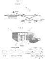
- a ring 4-mirror bowtie frequency converter 10 representative of a great variety of external ring cavity configurations, is frequently used due to its versatility and relative ease of implementation.
- the resonator 10 is configured with a non-linear ("NL") crystal 12 located in a beam waist between two concave mirrors M3, M4.
- NL non-linear
- the placement of crystal 12 in the beam's waist provides high frequency conversion efficiency.
- the crystal in this position suffers from high optical power density of the frequency-converted beam at the crystal's output face and inside the crystal's volume.
- high energy photons at the converted wavelength are incident on the output surface of crystal 12 and can degrade this surface, while a high power density around the beam waist can damage the bulk of crystal 12.
- the damage to the output surface can be minimized, of course, by reducing the power density on the output surface via reducing the size of the waist. As the latter reduces, the beam divergence increases reducing optical power density on the output surface of the crystal. However, scaling down the beam waist increases an already high power density within the waist in the crystal which can initiate damage in the bulk of the crystal.
- the frequency conversion efficiency of the external converter resonator is another concern.
- the conversion efficiency critically depends on making the resonator impedance matched, among other factors.
- the impedance matching involves the optimization of cavity parameters (most commonly transmission of the input mirror) to maximize the coupling of light into the resonant, cavity. Maximum coupling is obtained when the round trip losses of the converter (including frequency conversion) are equal to the transmission T of the coupling mirror M1.
- the resonator is impedance matched when the coefficient of transmission T of the mirror M1 substantially matches the single pass frequency conversion efficiency in crystal 12, provided other cavity losses are negligible.
- the present invention discloses a frequency convertor which operates with improved crystal's life and manufacturability.
- the volume and input and output faces of a NL crystal are all optically unloaded which considerably prolongs the useful life of the crystal. Structurally, this aspect is realized by further disclosed resonator configurations.
- the crystal is displaced from a traditional position within the resonator, in which the input beam is focused inside the crystal, to a position where the NL crystal is located beyond the beam waist.
- the power density inside the volume and at least on the output crystal face is substantially decreased compared to the traditional geometry.
- the other configuration of the first aspect includes placing the NL crystal in a collimated beam within the resonator. Like in the previously disclosed embodiment, the power density of the incident and converted beams is reduced which increases the useful life of the crystal.
- the NL crystal is selectively placed in the divergent beam in multiple positions, corresponding to respective powers of input light at the fundamental frequency, in which the resonator is impedance matched and thus operates at the maximum conversion efficiency.
- the placement of the crystal may be realized manually or automatically.
- the automatic displacement involves moving the NL crystal along the divergent beam until the impedance matching condition of the resonator at the given power of input signal is achieved.
- the determination is realized by a closed loop feedback monitoring either one of or both the intensity of the output signal at the desired converted frequency and the intensity of the input signal reflected from the input mirror.
- the crystal may be positioned manually at one of discrete predetermined locations, which corresponds to maximum conversion efficiency for this power, without the use of a control circuit.
- the disclosed resonator is adapted to operate at optimal efficiency over a wide range of input light powers without replacing any of the mirrors and/or NL crystal.
- the possibility of using the same physical components of the resonator for different input powers facilitates manufacturing and exploitation of resonators.
- FIGs. 2 and 3 The fiber laser system of FIGs. 2 and 3 is illustrated exclusively as an example of any continuous wave, single frequency single mode laser system operating at the desired fundamental wavelength in conjunction with the disclosed resonator.
- the bow-tie geometry of the disclosed resonator is also exemplary and can be replaced by any ring-cavity configuration known to an artisan.
- same or similar reference numerals are used in the drawings and the description to refer to the same or like parts or steps.
- the drawings are in simplified form and ate not necessarily to the scale.
- the terms "connect,” “couple,” and similar terms with their inflectional morphemes do not necessarily denote direct and immediate connections, but also include connections through intermediate elements or devices.
- the disclosed structure and method represent a modification to the traditional external cavity frequency converter resonator.
- This modification results in reduction of optical power density of the frequency-converted radiation at the output face and in the volume of a nonlinear crystal, which significantly slows down the rate of crystal degradation and improves the frequency converter's lifetime.
- This is achieved by shifting the nonlinear crystal inside the resonator away from the waist of the beam at the fundamental frequency to a location where this beam is divergent.
- the crystal is shifted to a location inside the resonator where the beam at the fundamental frequency is collimated.
- FIGs. 2 and 3 illustrate an exemplary CW single frequency, single mode fiber laser system 14, disclosed in US. Prov. Application No. 61/594,395 and co-owned with the present application by common assignee.
- the system 14 includes a module 16, outputting a single mode (“SM”) linearly polarized light at the desired fundamental wavelength in a 1 ⁇ m range, and a laser head 19.
- the module 16 is configured with, among others, a single frequency laser diode (“SFLD”) outputting the signal light at a fundamental wavelength of about 1064 nm, and one or multiple linearly polarized single frequency ytterbium fiber pre-amplifiers.
- SFLD single frequency laser diode
- the laser head 19 includes a booster amplifier, collimator and a 2nd harmonie generation resonator outputting a green beam 20 at the wavelength of about 532 nm. While the fiber laser is preferred, other lasers, such as solid state, semiconductor, disk and other laser configurations, are fully incorporated within the scope of this disclosure.
- exemplary frequency converter 18 includes an input partially transmitting flat mirror 22 coupling collimated light at the fundamental frequency into the resonator, a first intermediary flat mirror 24, a concave mirror 26 and a concave output mirror 28 all defining a closed beam path.
- the concave mirror 26 focuses the incident collimated beam into a beam waist 30 where the beam diameter is the smallest.
- the number of optical elements may vary, and the converted beam can be extracted from resonator 18 not only by mirror 28 but, alternatively, by any other optical element such as mirror 31 shown in dash lines in FIG. 3 .
- the non-linear crystal is placed midpoint between concave mirrors 26 and 28 with the fundamental beam waist located inside the crystal.
- This position of the crystal 32 is characterized by a high optical power density of the converted light inside the volume of and on the output face 34 of crystal 32.
- the high power density can damage crystal bulk and/or face which limits the useful life of the converter.
- crystal 32 is linearly displaced from beam waist 30 along the divergent beam towards output mirror 28.
- the divergent beam is a beam that has a Rayleigh range which is smaller than a cavity round trip in frequency converter 18.
- the optical power density of the frequency-converted radiation in the volume and at output face 34 of nonlinear crystal 32 can be substantially reduced thereby increasing the lifetime of non-linear crystal 32. If crystal 32 is further displaced, not only the volume and output face are under the reduced intensity, but also the input face of crystal 32 is unloaded.
- the placement of crystal 32 in FIG, 4 is not arbitrary. For a wide range of input powers, the placement is determined so that for any given input power, the location of the crystal corresponds to impedance matching condition of resonator 18.
- the desired placement of crystal 32 can be determined prior to the operation of frequency converter 18 provided the input power is known.
- the placement of the crystal may be realized manually.
- displacement of crystal 32 may be realized by any suitable actuator 36 along a divergent beam so as to meet the impedance matching condition, i.e., maximum frequency conversion efficiency, for a wide range of input powers.
- the impedance matching condition for any input power can be determined by a closed loop circuitry.
- a sensor 40 detects the output frequency converted power, a maximum of which corresponds to the maximum, conversion efficiency for a given input power.
- sensor 40 may also be used to monitor the power of the input beam reflected from input mirror 22 and utilize a feedback loop to minimize this power. This also corresponds to the impedance matching condition.
- FIG. 5 illustrates another embodiment of the disclosed frequency converter configured to reduce power density inside the volume and at the opposite faces of crystal 32.
- crystal 32 is placed in the collimated beam between input and intermediate mirrors 22 and 24, respectively.
- the collimated beam is a beam that has a Rayleigh range which is larger than a cavity round trip in resonant cavity 18.
- crystal 32 may be placed along any section of the beam path within cavity 18 including beam waist 30.
- the embodiment shown in this figure, like in FIG. 4 is exemplary and can be configured with three, four or more optical components as long as there is at least one focusing optical element that compensates for the natural divergence of a collimated beam.
- the experimental data obtained with the disclosed resonator shows conversion efficiency in excess of 90%. Furthermore, the disclosed resonator is configured so that optical power density of the frequency-converted radiation at the crystal's output face and inside the crystal is at least an order of magnitude lower compared to traditional resonator 10 of FIG. 1 . It means that the lifetime of frequency converters with crystals located in a divergent or collimated beam will be significantly improved compared to frequency converters with crystals located in the beam waist.
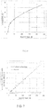
- FIG. 6 shows the crystal shift required to achieve the impedance matching condition for this specific converter for a given input power.
- FIG. 7 illustrates the power density of the frequency converted radiation on the exit face of the nonlinear crystal for a range of input powers in the disclosed configuration compared to the known prior art configuration.
- the disclosed and prior art configurations are both impedance matched for each point within the shown range of input powers.
- the power density at the exit crystal face does not significantly vary over a wide range of input powers for the disclosed configuration. While the input IR power increases from 12 W to about 230 W, i.e., about 20 times, the crystal is displaced further away from the beam waist. At the same time, the green power density at the exit crystal face increases by about mere 2.8 times. In contrast, the green power density in the prior art configuration grows linearly by about 20 times as the input power increases.
- the following table I provides a comparison between two configurations impedance matched for 230 W input IR power (atmost right points in FIG. 7 ),
- the two configurations feature the identical efficiency and output power.
- not only the green power density on the exit face is decreased, but also both IR and green power densities inside the volume of crystal 32 are substantially decreased in the disclosed configuration.
- the decreased power density in the bulk material relaxes the requirements for crystal purity. The latter, of course, represents an additional advantage of the disclosed configuration.
- the power density of light at both the fundamental and converted frequencies reduces inside the crystal as it moves farther away from the waist.
- the power density of the converted frequency at the exit face of the crystal lowers with the distance between the crystal and waste.
- the disclosed frequency converter may include multiple disclosed resonators that are coupled in series for third, fourth or higher order harmonic generation, or other non-linear frequency conversion.
- CW single-mode single-frequency fiber laser incorporating the above disclosed frequency converter has been demonstrated to output several hundred watts at a converted wavelength and operate at 25% and higher electrical-to-optical efficiency.
- the output power at a converted frequency is limited only by the fundamental fiber laser power and even today can reach a kW-level.
- the useful life of a NL crystal for the disclosed resonator is substantially longer than that of the crystal in the traditional configuration.
- the ability to adjust the disclosed resonator to provide high frequency conversion efficiency at different powers without a need for replacing any of the physical components is highly advantageous for the manufacturing process.
- the crystal 32 can be selected in response to given requirements and thus may include any non-linear crystal (for example, lithium triborate (LBO), barium borate (BBO), potassium titanyl phosphate (KTP), potassium di*deuterium phosphate (KD*P), potassium dihydrogen phosphate (KDP) and others).
- LBO lithium triborate
- BBO barium borate
- KTP potassium titanyl phosphate
- KD*P potassium di*deuterium phosphate
- KDP potassium dihydrogen phosphate
- resonators are not limited to those shown and discussed above.
- the resonator may not only be unidirectional, but also it may be bi-directional.
- various changes, modifications, and adaptations may be effected therein by one skilled in the art without departing from the scope of the invention as disclosed above.
Landscapes
- Physics & Mathematics (AREA)
- Nonlinear Science (AREA)
- Optics & Photonics (AREA)
- General Physics & Mathematics (AREA)
- Optical Modulation, Optical Deflection, Nonlinear Optics, Optical Demodulation, Optical Logic Elements (AREA)
- Electromagnetism (AREA)
- Engineering & Computer Science (AREA)
- Plasma & Fusion (AREA)
- Lasers (AREA)
Claims (4)
- Frequenzumsetzer (18) zum Umsetzen eines Einmoden-(SM-) Eingangsstrahls, der von einer Laserlichtquelle mit einer Grundfrequenz emittiert wird, in einen Ausgangsstrahl mit einer umgesetzten Frequenz, wobei der Frequenzumsetzer umfasst:mehrere beabstandete optische Komponenten (22, 24, 26, 28, 31), die einen externen Hohlraumresonator definieren und dafür konfiguriert sind, den Eingangsstrahl mit wenigstens einer Strahlentaille (30) in dem Hohlraum zu formen, wobei der geformte Strahl einen Abschnitt aufweist, der aus der Gruppe gewählt ist, die aus wenigsten einem divergenten Abschnitt, einem kollimierten Abschnitt und einer Kombination dieser besteht, undeinen nichtlinearen Kristall (32), der in dem Hohlraum platziert ist,dadurch gekennzeichnet, dassder Einmoden- (SM-) Eingangsstrahl mit einer Leistung des Einmoden- (SM-) Eingangsstrahls emittiert wird, die über einen Bereich größer als 12 W, vorzugsweise zwischen 12 W und einem kW-Niveau, variiert,der Frequenzumsetzer (18) über den Bereich von Eingangsstrahlleistungen arbeitet und ferner den nichtlinearen Kristall (32) umfasst, der in dem Hohlraum platziert ist, in:dem Abschnitt des divergenten Strahls des geformten Strahls mit einem Rayleigh-Bereich kleiner als eine Umlauflänge des Hohlraums, wobei der Kristall so platziert ist, dass eine Mitte des Kristalls entlang eines Strahlenwegs von der Strahlentaille (30) beabstandet ist, oderdem Abschnitt des kollimierten Strahls mit einem Rayleigh-Bereich größer als der Umlauflänge;und wobei der Frequenzumsetzer (18) ferner dadurch gekennzeichnet ist, dass der nichtlineare Kristall in dem Resonator entlang des divergenten Abschnitts unter mehreren Orten, die jeweiligen Eingangsleistungen des Bereichs entsprechen, in der Weise verlagert werden kann, dass jeder Ort des Resonators impedanzangepasst ist und dass der nichtlineare Kristall die zweite, die dritte, die vierte Harmonische und/oder die Harmonische höherer Ordnung mit einem maximalen Umsetzungswirkungsgrad erzeugt.
- Optisches System, das umfasst:den Frequenzumsetzer (18) nach Anspruch 1;wobei der Einmoden- (SM-) Strahl mit einer Grundfrequenz durch eine kohärente Dauerstrich- (CW-) Einfrequenz- (SF-) Quelle (16) emittiert wird; undwobei ein Kollimator dafür konfiguriert ist, den Strahl auslassseitig der Dauerstrich- (CW-) Quelle (16) zu kollimieren;undwobei ein Resonator zum Erzeugen der zweiten, der dritten, der vierten Harmonischen und/oder der Harmonischen höherer Ordnung aus dem Einmoden- (SM-) Strahl außerhalb der Dauerstrich- (CW-) Einfrequenz- (SF-) Quelle platziert ist.
- Optisches System nach Anspruch 2, wobei die kohärente Dauerstrich- (CW-) Einfrequenz- (SF-) Quelle (16) einen Faserlaser oder einen Halbleiterlaser oder einen Festkörperlaser oder einen Gaslaser enthält.
- Optisches System nach Anspruch 2, das ferner umfasst:einen Laserkopf, der von der kohärenten Dauerstrich- (CW-) Einfrequenz- (SF-) Quelle (16) beabstandet ist,einen Booster-Faserverstärker, der den Einmoden- (SM-) Strahl mit der Grundfrequenz verstärkt und der zusammen mit dem Resonator in dem Laserkopf montiert ist, undein Faserkabel, das die kohärente Dauerstrich- (CW-) Einfrequenz- (SF-) Quelle (16) und den Booster koppelt.
Applications Claiming Priority (1)
| Application Number | Priority Date | Filing Date | Title |
|---|---|---|---|
| PCT/US2012/060545 WO2014062173A1 (en) | 2012-10-17 | 2012-10-17 | Resonantly enhanced frequency converter |
Publications (3)
| Publication Number | Publication Date |
|---|---|
| EP2909899A1 EP2909899A1 (de) | 2015-08-26 |
| EP2909899A4 EP2909899A4 (de) | 2016-06-29 |
| EP2909899B1 true EP2909899B1 (de) | 2020-06-17 |
Family
ID=50488598
Family Applications (1)
| Application Number | Title | Priority Date | Filing Date |
|---|---|---|---|
| EP12886888.2A Active EP2909899B1 (de) | 2012-10-17 | 2012-10-17 | Resonanzverstärkter frequenzumrichter |
Country Status (5)
| Country | Link |
|---|---|
| EP (1) | EP2909899B1 (de) |
| JP (1) | JP6367813B2 (de) |
| KR (1) | KR101944434B1 (de) |
| CN (1) | CN104854764B (de) |
| WO (1) | WO2014062173A1 (de) |
Families Citing this family (3)
| Publication number | Priority date | Publication date | Assignee | Title |
|---|---|---|---|---|
| DE102014218353B4 (de) * | 2014-09-12 | 2020-03-12 | Crylas Crystal Laser Systems Gmbh | Laseranordnung und Verfahren zur Erhöhung der Lebensdaueroptischer Elemente in einer Laseranordnung |
| US9841655B2 (en) * | 2015-07-01 | 2017-12-12 | Kla-Tencor Corporation | Power scalable nonlinear optical wavelength converter |
| JP7176738B2 (ja) * | 2016-11-16 | 2022-11-22 | 国立大学法人電気通信大学 | レーザ共振器、及びレーザ共振器の設計方法 |
Family Cites Families (14)
| Publication number | Priority date | Publication date | Assignee | Title |
|---|---|---|---|---|
| US4731795A (en) * | 1986-06-26 | 1988-03-15 | Amoco Corporation | Solid state laser |
| JPH03272188A (ja) * | 1990-03-15 | 1991-12-03 | Max Planck Ges Foerderung Wissenschaft Ev | 固体レーザ |
| JPH08320509A (ja) * | 1995-05-24 | 1996-12-03 | Asahi Glass Co Ltd | 高調波発生装置 |
| JPH11344734A (ja) * | 1998-06-03 | 1999-12-14 | Ishikawajima Harima Heavy Ind Co Ltd | 光軸位置補正装置及び第2高調波発生装置 |
| US6298076B1 (en) * | 1999-03-05 | 2001-10-02 | Coherent, Inc. | High-power external-cavity optically-pumped semiconductor lasers |
| JP2001042370A (ja) * | 1999-07-27 | 2001-02-16 | Ushio Sogo Gijutsu Kenkyusho:Kk | 波長変換装置 |
| US20060029120A1 (en) * | 2000-03-06 | 2006-02-09 | Novalux Inc. | Coupled cavity high power semiconductor laser |
| JP3885529B2 (ja) * | 2001-08-06 | 2007-02-21 | ソニー株式会社 | レーザー光発生装置 |
| US7620077B2 (en) * | 2005-07-08 | 2009-11-17 | Lockheed Martin Corporation | Apparatus and method for pumping and operating optical parametric oscillators using DFB fiber lasers |
| JP4886269B2 (ja) * | 2005-10-28 | 2012-02-29 | 株式会社ニデック | 医療用レーザ装置 |
| US8125703B2 (en) * | 2007-03-22 | 2012-02-28 | Panasonic Corporation | Wavelength converter and image display with wavelength converter |
| ATE535971T1 (de) * | 2007-07-30 | 2011-12-15 | Mitsubishi Electric Corp | Laseranordnung zur wellenlängenumsetzung |
| US20100278200A1 (en) * | 2009-05-04 | 2010-11-04 | Coherent, Inc. | External frequency-quadruped 1064 nm mode-locked laser |
| US8243764B2 (en) * | 2010-04-01 | 2012-08-14 | Tucker Derek A | Frequency conversion of a laser beam using a partially phase-mismatched nonlinear crystal |
-
2012
- 2012-10-17 EP EP12886888.2A patent/EP2909899B1/de active Active
- 2012-10-17 KR KR1020157012746A patent/KR101944434B1/ko active Active
- 2012-10-17 CN CN201280077704.8A patent/CN104854764B/zh active Active
- 2012-10-17 JP JP2015537671A patent/JP6367813B2/ja active Active
- 2012-10-17 WO PCT/US2012/060545 patent/WO2014062173A1/en not_active Ceased
Non-Patent Citations (1)
| Title |
|---|
| None * |
Also Published As
| Publication number | Publication date |
|---|---|
| CN104854764B (zh) | 2017-12-05 |
| WO2014062173A1 (en) | 2014-04-24 |
| JP2015536473A (ja) | 2015-12-21 |
| EP2909899A4 (de) | 2016-06-29 |
| KR101944434B1 (ko) | 2019-01-31 |
| CN104854764A (zh) | 2015-08-19 |
| JP6367813B2 (ja) | 2018-08-01 |
| EP2909899A1 (de) | 2015-08-26 |
| KR20150070333A (ko) | 2015-06-24 |
Similar Documents
| Publication | Publication Date | Title |
|---|---|---|
| US6816520B1 (en) | Solid state system and method for generating ultraviolet light | |
| US7443903B2 (en) | Laser apparatus having multiple synchronous amplifiers tied to one master oscillator | |
| KR100375850B1 (ko) | 고전력 레이저 장치 | |
| US20110064096A1 (en) | Mid-IR laser employing Tm fiber laser and optical parametric oscillator | |
| CN103299494A (zh) | 中红外和远红外的紧凑的高亮度光源 | |
| JP3939928B2 (ja) | 波長変換装置 | |
| US7733926B2 (en) | Thulium laser pumped Mid-IR source with broadbanded output | |
| US9429814B2 (en) | Laser arrangement and method for enhancing the life span of optical elements in a laser arrangement | |
| EP2909899B1 (de) | Resonanzverstärkter frequenzumrichter | |
| CN112688144A (zh) | 基于腔外双通倍频结构的激光器 | |
| Gorobets et al. | Studies of nonlinear optical characteristics of IR crystals for frequency conversion of TEA-CO2 laser radiation | |
| US10209604B2 (en) | Resonant enhanced frequency converter | |
| JP6678694B2 (ja) | 共鳴増強周波数変換器 | |
| EP1782512A2 (de) | Injektionsgekoppeltes hochleistungslasersystem | |
| JP4071806B2 (ja) | 波長変換装置 | |
| CN120473808B (zh) | 一种多波长红外激光输出装置 | |
| CN222691087U (zh) | 一种倍频激光设备 | |
| JP4945934B2 (ja) | 光学システム、検査装置、処理装置および測定装置 | |
| Morton et al. | 1W CW red VECSEL frequency-doubled to generate 60mW in the ultraviolet | |
| US20230031153A1 (en) | Device Component Assembly And Manufacturing Method Thereof | |
| CN107565356A (zh) | 一种百瓦级1.9微米固体激光发生装置 | |
| Babin et al. | Frequency doubling in the enhancement cavity with single focusing mirror | |
| Schmitt et al. | cw, 325nm, 100mW semiconductor laser system as potential substitute for HeCd gas lasers | |
| CN118380847A (zh) | 一种深紫外激光装置及生成方法 | |
| Shutong et al. | 1.5 µm optical vortex parametric oscillator based on KTA |
Legal Events
| Date | Code | Title | Description |
|---|---|---|---|
| PUAI | Public reference made under article 153(3) epc to a published international application that has entered the european phase |
Free format text: ORIGINAL CODE: 0009012 |
|
| 17P | Request for examination filed |
Effective date: 20150418 |
|
| AK | Designated contracting states |
Kind code of ref document: A1 Designated state(s): AL AT BE BG CH CY CZ DE DK EE ES FI FR GB GR HR HU IE IS IT LI LT LU LV MC MK MT NL NO PL PT RO RS SE SI SK SM TR |
|
| AX | Request for extension of the european patent |
Extension state: BA ME |
|
| DAX | Request for extension of the european patent (deleted) | ||
| REG | Reference to a national code |
Ref country code: DE Ref legal event code: R079 Ref document number: 602012070812 Country of ref document: DE Free format text: PREVIOUS MAIN CLASS: H01S0003100000 Ipc: G02F0001370000 |
|
| RA4 | Supplementary search report drawn up and despatched (corrected) |
Effective date: 20160530 |
|
| RIC1 | Information provided on ipc code assigned before grant |
Ipc: G02F 1/35 20060101ALI20160523BHEP Ipc: G02F 1/37 20060101AFI20160523BHEP Ipc: H01S 3/00 20060101ALI20160523BHEP |
|
| STAA | Information on the status of an ep patent application or granted ep patent |
Free format text: STATUS: EXAMINATION IS IN PROGRESS |
|
| 17Q | First examination report despatched |
Effective date: 20170323 |
|
| GRAP | Despatch of communication of intention to grant a patent |
Free format text: ORIGINAL CODE: EPIDOSNIGR1 |
|
| STAA | Information on the status of an ep patent application or granted ep patent |
Free format text: STATUS: GRANT OF PATENT IS INTENDED |
|
| INTG | Intention to grant announced |
Effective date: 20200110 |
|
| GRAS | Grant fee paid |
Free format text: ORIGINAL CODE: EPIDOSNIGR3 |
|
| GRAA | (expected) grant |
Free format text: ORIGINAL CODE: 0009210 |
|
| STAA | Information on the status of an ep patent application or granted ep patent |
Free format text: STATUS: THE PATENT HAS BEEN GRANTED |
|
| AK | Designated contracting states |
Kind code of ref document: B1 Designated state(s): AL AT BE BG CH CY CZ DE DK EE ES FI FR GB GR HR HU IE IS IT LI LT LU LV MC MK MT NL NO PL PT RO RS SE SI SK SM TR |
|
| REG | Reference to a national code |
Ref country code: GB Ref legal event code: FG4D |
|
| REG | Reference to a national code |
Ref country code: CH Ref legal event code: EP |
|
| REG | Reference to a national code |
Ref country code: IE Ref legal event code: FG4D |
|
| REG | Reference to a national code |
Ref country code: DE Ref legal event code: R096 Ref document number: 602012070812 Country of ref document: DE |
|
| REG | Reference to a national code |
Ref country code: AT Ref legal event code: REF Ref document number: 1282055 Country of ref document: AT Kind code of ref document: T Effective date: 20200715 |
|
| PG25 | Lapsed in a contracting state [announced via postgrant information from national office to epo] |
Ref country code: LT Free format text: LAPSE BECAUSE OF FAILURE TO SUBMIT A TRANSLATION OF THE DESCRIPTION OR TO PAY THE FEE WITHIN THE PRESCRIBED TIME-LIMIT Effective date: 20200617 Ref country code: NO Free format text: LAPSE BECAUSE OF FAILURE TO SUBMIT A TRANSLATION OF THE DESCRIPTION OR TO PAY THE FEE WITHIN THE PRESCRIBED TIME-LIMIT Effective date: 20200917 Ref country code: SE Free format text: LAPSE BECAUSE OF FAILURE TO SUBMIT A TRANSLATION OF THE DESCRIPTION OR TO PAY THE FEE WITHIN THE PRESCRIBED TIME-LIMIT Effective date: 20200617 Ref country code: FI Free format text: LAPSE BECAUSE OF FAILURE TO SUBMIT A TRANSLATION OF THE DESCRIPTION OR TO PAY THE FEE WITHIN THE PRESCRIBED TIME-LIMIT Effective date: 20200617 Ref country code: GR Free format text: LAPSE BECAUSE OF FAILURE TO SUBMIT A TRANSLATION OF THE DESCRIPTION OR TO PAY THE FEE WITHIN THE PRESCRIBED TIME-LIMIT Effective date: 20200918 |
|
| REG | Reference to a national code |
Ref country code: LT Ref legal event code: MG4D |
|
| REG | Reference to a national code |
Ref country code: NL Ref legal event code: MP Effective date: 20200617 |
|
| PG25 | Lapsed in a contracting state [announced via postgrant information from national office to epo] |
Ref country code: RS Free format text: LAPSE BECAUSE OF FAILURE TO SUBMIT A TRANSLATION OF THE DESCRIPTION OR TO PAY THE FEE WITHIN THE PRESCRIBED TIME-LIMIT Effective date: 20200617 Ref country code: HR Free format text: LAPSE BECAUSE OF FAILURE TO SUBMIT A TRANSLATION OF THE DESCRIPTION OR TO PAY THE FEE WITHIN THE PRESCRIBED TIME-LIMIT Effective date: 20200617 Ref country code: LV Free format text: LAPSE BECAUSE OF FAILURE TO SUBMIT A TRANSLATION OF THE DESCRIPTION OR TO PAY THE FEE WITHIN THE PRESCRIBED TIME-LIMIT Effective date: 20200617 Ref country code: BG Free format text: LAPSE BECAUSE OF FAILURE TO SUBMIT A TRANSLATION OF THE DESCRIPTION OR TO PAY THE FEE WITHIN THE PRESCRIBED TIME-LIMIT Effective date: 20200917 |
|
| REG | Reference to a national code |
Ref country code: AT Ref legal event code: MK05 Ref document number: 1282055 Country of ref document: AT Kind code of ref document: T Effective date: 20200617 |
|
| PG25 | Lapsed in a contracting state [announced via postgrant information from national office to epo] |
Ref country code: NL Free format text: LAPSE BECAUSE OF FAILURE TO SUBMIT A TRANSLATION OF THE DESCRIPTION OR TO PAY THE FEE WITHIN THE PRESCRIBED TIME-LIMIT Effective date: 20200617 Ref country code: AL Free format text: LAPSE BECAUSE OF FAILURE TO SUBMIT A TRANSLATION OF THE DESCRIPTION OR TO PAY THE FEE WITHIN THE PRESCRIBED TIME-LIMIT Effective date: 20200617 |
|
| PG25 | Lapsed in a contracting state [announced via postgrant information from national office to epo] |
Ref country code: CZ Free format text: LAPSE BECAUSE OF FAILURE TO SUBMIT A TRANSLATION OF THE DESCRIPTION OR TO PAY THE FEE WITHIN THE PRESCRIBED TIME-LIMIT Effective date: 20200617 Ref country code: ES Free format text: LAPSE BECAUSE OF FAILURE TO SUBMIT A TRANSLATION OF THE DESCRIPTION OR TO PAY THE FEE WITHIN THE PRESCRIBED TIME-LIMIT Effective date: 20200617 Ref country code: RO Free format text: LAPSE BECAUSE OF FAILURE TO SUBMIT A TRANSLATION OF THE DESCRIPTION OR TO PAY THE FEE WITHIN THE PRESCRIBED TIME-LIMIT Effective date: 20200617 Ref country code: IT Free format text: LAPSE BECAUSE OF FAILURE TO SUBMIT A TRANSLATION OF THE DESCRIPTION OR TO PAY THE FEE WITHIN THE PRESCRIBED TIME-LIMIT Effective date: 20200617 Ref country code: SM Free format text: LAPSE BECAUSE OF FAILURE TO SUBMIT A TRANSLATION OF THE DESCRIPTION OR TO PAY THE FEE WITHIN THE PRESCRIBED TIME-LIMIT Effective date: 20200617 Ref country code: AT Free format text: LAPSE BECAUSE OF FAILURE TO SUBMIT A TRANSLATION OF THE DESCRIPTION OR TO PAY THE FEE WITHIN THE PRESCRIBED TIME-LIMIT Effective date: 20200617 Ref country code: EE Free format text: LAPSE BECAUSE OF FAILURE TO SUBMIT A TRANSLATION OF THE DESCRIPTION OR TO PAY THE FEE WITHIN THE PRESCRIBED TIME-LIMIT Effective date: 20200617 Ref country code: PT Free format text: LAPSE BECAUSE OF FAILURE TO SUBMIT A TRANSLATION OF THE DESCRIPTION OR TO PAY THE FEE WITHIN THE PRESCRIBED TIME-LIMIT Effective date: 20201019 |
|
| PG25 | Lapsed in a contracting state [announced via postgrant information from national office to epo] |
Ref country code: SK Free format text: LAPSE BECAUSE OF FAILURE TO SUBMIT A TRANSLATION OF THE DESCRIPTION OR TO PAY THE FEE WITHIN THE PRESCRIBED TIME-LIMIT Effective date: 20200617 Ref country code: PL Free format text: LAPSE BECAUSE OF FAILURE TO SUBMIT A TRANSLATION OF THE DESCRIPTION OR TO PAY THE FEE WITHIN THE PRESCRIBED TIME-LIMIT Effective date: 20200617 Ref country code: IS Free format text: LAPSE BECAUSE OF FAILURE TO SUBMIT A TRANSLATION OF THE DESCRIPTION OR TO PAY THE FEE WITHIN THE PRESCRIBED TIME-LIMIT Effective date: 20201017 |
|
| REG | Reference to a national code |
Ref country code: DE Ref legal event code: R097 Ref document number: 602012070812 Country of ref document: DE |
|
| PLBE | No opposition filed within time limit |
Free format text: ORIGINAL CODE: 0009261 |
|
| STAA | Information on the status of an ep patent application or granted ep patent |
Free format text: STATUS: NO OPPOSITION FILED WITHIN TIME LIMIT |
|
| PG25 | Lapsed in a contracting state [announced via postgrant information from national office to epo] |
Ref country code: DK Free format text: LAPSE BECAUSE OF FAILURE TO SUBMIT A TRANSLATION OF THE DESCRIPTION OR TO PAY THE FEE WITHIN THE PRESCRIBED TIME-LIMIT Effective date: 20200617 |
|
| 26N | No opposition filed |
Effective date: 20210318 |
|
| PG25 | Lapsed in a contracting state [announced via postgrant information from national office to epo] |
Ref country code: SI Free format text: LAPSE BECAUSE OF FAILURE TO SUBMIT A TRANSLATION OF THE DESCRIPTION OR TO PAY THE FEE WITHIN THE PRESCRIBED TIME-LIMIT Effective date: 20200617 |
|
| REG | Reference to a national code |
Ref country code: CH Ref legal event code: PL |
|
| PG25 | Lapsed in a contracting state [announced via postgrant information from national office to epo] |
Ref country code: MC Free format text: LAPSE BECAUSE OF FAILURE TO SUBMIT A TRANSLATION OF THE DESCRIPTION OR TO PAY THE FEE WITHIN THE PRESCRIBED TIME-LIMIT Effective date: 20200617 Ref country code: LU Free format text: LAPSE BECAUSE OF NON-PAYMENT OF DUE FEES Effective date: 20201017 |
|
| REG | Reference to a national code |
Ref country code: BE Ref legal event code: MM Effective date: 20201031 |
|
| PG25 | Lapsed in a contracting state [announced via postgrant information from national office to epo] |
Ref country code: LI Free format text: LAPSE BECAUSE OF NON-PAYMENT OF DUE FEES Effective date: 20201031 Ref country code: BE Free format text: LAPSE BECAUSE OF NON-PAYMENT OF DUE FEES Effective date: 20201031 Ref country code: CH Free format text: LAPSE BECAUSE OF NON-PAYMENT OF DUE FEES Effective date: 20201031 |
|
| PG25 | Lapsed in a contracting state [announced via postgrant information from national office to epo] |
Ref country code: IE Free format text: LAPSE BECAUSE OF NON-PAYMENT OF DUE FEES Effective date: 20201017 |
|
| PG25 | Lapsed in a contracting state [announced via postgrant information from national office to epo] |
Ref country code: TR Free format text: LAPSE BECAUSE OF FAILURE TO SUBMIT A TRANSLATION OF THE DESCRIPTION OR TO PAY THE FEE WITHIN THE PRESCRIBED TIME-LIMIT Effective date: 20200617 Ref country code: MT Free format text: LAPSE BECAUSE OF FAILURE TO SUBMIT A TRANSLATION OF THE DESCRIPTION OR TO PAY THE FEE WITHIN THE PRESCRIBED TIME-LIMIT Effective date: 20200617 Ref country code: CY Free format text: LAPSE BECAUSE OF FAILURE TO SUBMIT A TRANSLATION OF THE DESCRIPTION OR TO PAY THE FEE WITHIN THE PRESCRIBED TIME-LIMIT Effective date: 20200617 |
|
| PG25 | Lapsed in a contracting state [announced via postgrant information from national office to epo] |
Ref country code: MK Free format text: LAPSE BECAUSE OF FAILURE TO SUBMIT A TRANSLATION OF THE DESCRIPTION OR TO PAY THE FEE WITHIN THE PRESCRIBED TIME-LIMIT Effective date: 20200617 |
|
| P01 | Opt-out of the competence of the unified patent court (upc) registered |
Effective date: 20230527 |
|
| PGFP | Annual fee paid to national office [announced via postgrant information from national office to epo] |
Ref country code: GB Payment date: 20250923 Year of fee payment: 14 |
|
| PGFP | Annual fee paid to national office [announced via postgrant information from national office to epo] |
Ref country code: FR Payment date: 20250924 Year of fee payment: 14 |
|
| PGFP | Annual fee paid to national office [announced via postgrant information from national office to epo] |
Ref country code: DE Payment date: 20250923 Year of fee payment: 14 |