EP2909579B1 - Surveying system and method - Google Patents
Surveying system and method Download PDFInfo
- Publication number
- EP2909579B1 EP2909579B1 EP13776519.4A EP13776519A EP2909579B1 EP 2909579 B1 EP2909579 B1 EP 2909579B1 EP 13776519 A EP13776519 A EP 13776519A EP 2909579 B1 EP2909579 B1 EP 2909579B1
- Authority
- EP
- European Patent Office
- Prior art keywords
- inertial
- referenced
- attitude
- giving means
- measuring unit
- Prior art date
- Legal status (The legal status is an assumption and is not a legal conclusion. Google has not performed a legal analysis and makes no representation as to the accuracy of the status listed.)
- Active
Links
- 238000000034 method Methods 0.000 title claims description 34
- 238000005259 measurement Methods 0.000 claims description 48
- 238000011156 evaluation Methods 0.000 claims description 39
- 238000012545 processing Methods 0.000 claims description 18
- 230000035945 sensitivity Effects 0.000 claims description 11
- 230000001133 acceleration Effects 0.000 claims description 10
- 239000013598 vector Substances 0.000 description 27
- 239000011159 matrix material Substances 0.000 description 9
- 230000033001 locomotion Effects 0.000 description 6
- 238000004519 manufacturing process Methods 0.000 description 5
- 239000000654 additive Substances 0.000 description 4
- 230000000996 additive effect Effects 0.000 description 4
- 230000000694 effects Effects 0.000 description 4
- 230000005484 gravity Effects 0.000 description 4
- 230000000644 propagated effect Effects 0.000 description 4
- 238000005295 random walk Methods 0.000 description 4
- 230000001276 controlling effect Effects 0.000 description 3
- 230000010354 integration Effects 0.000 description 3
- 238000005312 nonlinear dynamic Methods 0.000 description 3
- 239000006227 byproduct Substances 0.000 description 2
- 238000006243 chemical reaction Methods 0.000 description 2
- 238000001514 detection method Methods 0.000 description 2
- 238000005516 engineering process Methods 0.000 description 2
- 238000012986 modification Methods 0.000 description 2
- 230000004048 modification Effects 0.000 description 2
- 239000000047 product Substances 0.000 description 2
- 101000802640 Homo sapiens Lactosylceramide 4-alpha-galactosyltransferase Proteins 0.000 description 1
- 102100035838 Lactosylceramide 4-alpha-galactosyltransferase Human genes 0.000 description 1
- XUIMIQQOPSSXEZ-UHFFFAOYSA-N Silicon Chemical compound [Si] XUIMIQQOPSSXEZ-UHFFFAOYSA-N 0.000 description 1
- 238000013459 approach Methods 0.000 description 1
- 230000000295 complement effect Effects 0.000 description 1
- 238000010276 construction Methods 0.000 description 1
- 238000012937 correction Methods 0.000 description 1
- 230000002596 correlated effect Effects 0.000 description 1
- 238000006880 cross-coupling reaction Methods 0.000 description 1
- 230000001419 dependent effect Effects 0.000 description 1
- 238000011161 development Methods 0.000 description 1
- 230000018109 developmental process Effects 0.000 description 1
- -1 ferrous metals Chemical class 0.000 description 1
- 239000000835 fiber Substances 0.000 description 1
- 238000001914 filtration Methods 0.000 description 1
- 230000010006 flight Effects 0.000 description 1
- 230000004927 fusion Effects 0.000 description 1
- 230000014509 gene expression Effects 0.000 description 1
- 238000012886 linear function Methods 0.000 description 1
- 230000007774 longterm Effects 0.000 description 1
- 229910052751 metal Inorganic materials 0.000 description 1
- 239000002184 metal Substances 0.000 description 1
- 230000003287 optical effect Effects 0.000 description 1
- 238000007781 pre-processing Methods 0.000 description 1
- 230000001902 propagating effect Effects 0.000 description 1
- 230000035939 shock Effects 0.000 description 1
- 229910052710 silicon Inorganic materials 0.000 description 1
- 239000010703 silicon Substances 0.000 description 1
- 238000010561 standard procedure Methods 0.000 description 1
Images


Classifications
-
- G—PHYSICS
- G01—MEASURING; TESTING
- G01C—MEASURING DISTANCES, LEVELS OR BEARINGS; SURVEYING; NAVIGATION; GYROSCOPIC INSTRUMENTS; PHOTOGRAMMETRY OR VIDEOGRAMMETRY
- G01C15/00—Surveying instruments or accessories not provided for in groups G01C1/00 - G01C13/00
- G01C15/02—Means for marking measuring points
- G01C15/06—Surveyors' staffs; Movable markers
-
- G—PHYSICS
- G01—MEASURING; TESTING
- G01C—MEASURING DISTANCES, LEVELS OR BEARINGS; SURVEYING; NAVIGATION; GYROSCOPIC INSTRUMENTS; PHOTOGRAMMETRY OR VIDEOGRAMMETRY
- G01C21/00—Navigation; Navigational instruments not provided for in groups G01C1/00 - G01C19/00
- G01C21/10—Navigation; Navigational instruments not provided for in groups G01C1/00 - G01C19/00 by using measurements of speed or acceleration
- G01C21/12—Navigation; Navigational instruments not provided for in groups G01C1/00 - G01C19/00 by using measurements of speed or acceleration executed aboard the object being navigated; Dead reckoning
- G01C21/16—Navigation; Navigational instruments not provided for in groups G01C1/00 - G01C19/00 by using measurements of speed or acceleration executed aboard the object being navigated; Dead reckoning by integrating acceleration or speed, i.e. inertial navigation
- G01C21/165—Navigation; Navigational instruments not provided for in groups G01C1/00 - G01C19/00 by using measurements of speed or acceleration executed aboard the object being navigated; Dead reckoning by integrating acceleration or speed, i.e. inertial navigation combined with non-inertial navigation instruments
- G01C21/1654—Navigation; Navigational instruments not provided for in groups G01C1/00 - G01C19/00 by using measurements of speed or acceleration executed aboard the object being navigated; Dead reckoning by integrating acceleration or speed, i.e. inertial navigation combined with non-inertial navigation instruments with electromagnetic compass
-
- G—PHYSICS
- G01—MEASURING; TESTING
- G01C—MEASURING DISTANCES, LEVELS OR BEARINGS; SURVEYING; NAVIGATION; GYROSCOPIC INSTRUMENTS; PHOTOGRAMMETRY OR VIDEOGRAMMETRY
- G01C21/00—Navigation; Navigational instruments not provided for in groups G01C1/00 - G01C19/00
- G01C21/10—Navigation; Navigational instruments not provided for in groups G01C1/00 - G01C19/00 by using measurements of speed or acceleration
- G01C21/12—Navigation; Navigational instruments not provided for in groups G01C1/00 - G01C19/00 by using measurements of speed or acceleration executed aboard the object being navigated; Dead reckoning
- G01C21/16—Navigation; Navigational instruments not provided for in groups G01C1/00 - G01C19/00 by using measurements of speed or acceleration executed aboard the object being navigated; Dead reckoning by integrating acceleration or speed, i.e. inertial navigation
- G01C21/183—Compensation of inertial measurements, e.g. for temperature effects
- G01C21/188—Compensation of inertial measurements, e.g. for temperature effects for accumulated errors, e.g. by coupling inertial systems with absolute positioning systems
Definitions
- the invention pertains to a surveying system and a surveying method for measuring the position of a point on the ground with the help of a survey pole. It also pertains to an upgrade kit and a surveying module for such a surveying system and to a computer programme product for executing steps of such a surveying method.
- the measurement taken by the GNSS receiver does not directly correspond to the target point to be surveyed; rather, it is a position measurement of the so-called "phase-centre" of the GNSS antenna.
- Current practice is to mount the antenna on a pole and ensure the pole is perfectly vertical over the point of interest and compensate the position for the length of the pole. Levelling the pole, however, takes time and it would be desirable to take measurements of the target position without the need to level the pole.
- GNSS Global Navigation Satellite Systems
- GPS Global Positioning System
- RTK Real-Time Kinematic
- the position measured by the GNSS receiver is at the so-called "phase centre" of the GNSS antenna, which for a high-quality survey antenna is a well-quantified location generally near the mechanical centre of the antenna.
- the location of interest to the surveyor is not at the antenna, but at a point on the ground; the antenna is usually mounted on a pole to optimise the reception of GNSS signals.
- a levelling device whether a traditional spirit level or a more sophisticated arrangement of sensors, can be used to determine if a pole is upright to some degree of tolerance sufficient to take a measurement.
- this error can be compensated for, assuming one knows the length of the pole.
- Measuring the angle of the pole with respect to the ground is not a trivial exercise. Whilst measuring the angle of the pole from the vertical (the pitch and roll) can be accurately achieved through a number of methods (notably, measurement of local gravity using accelerometers or inclinometers), measuring the orientation of the pole with respect to True North (the yaw or azimuth) is considerably more difficult.
- the azimuth angle is able to be inferred from the GNSS velocity, since the vehicle is normally aligned with the direction of travel.
- GNSS velocity is not a reliable means of azimuth determination.
- a high-quality INS can navigate without reference to GNSS or other external measurements, making it useful for survey applications when GPS is unavailable. This is described, for instance in US 2009 024 325 A1 which describes an INS used in a surveying application with a GNSS solution being unavailable.
- an inertial navigation solution mathematically rotates and integrates the raw inertial sensor measures, small errors will accumulate and the position solution (and azimuth solution, which must be maintained as a by-product) will drift without bound.
- the drift problem of an INS has been studied extensively for some time.
- the drift in the position and attitude solution (and thereby the means to compensate for pole tilt) can be contained by intelligently fusing GNSS or other external measurements with an inertial navigation system - the so-called “Aided Inertial Navigation System” (AINS) - which has long existed in the aerospace industry and is now used in surveying applications.
- AINS Advanced Inertial Navigation System
- navigation grade refers to sensors that can be useful for standalone navigation for many hours, e.g. including Ring Laser Gyroscopes (RLG), whereas tactical grade generally refers to navigation requirements for short flights, e.g. including Fibre Optic Gyroscopes (FOG) - are undoubtedly useful in determining position and attitude (whether GNSS aided or otherwise), they are also very expensive, heavy, bulky and suffer from high power consumption.
- RLG Ring Laser Gyroscopes
- tactical grade generally refers to navigation requirements for short flights, e.g. including Fibre Optic Gyroscopes (FOG) - are undoubtedly useful in determining position and attitude (whether GNSS aided or otherwise), they are also very expensive, heavy, bulky and suffer from high power consumption.
- FOG Fibre Optic Gyroscopes
- MEMS inertial sensors are now routinely integrated into low-accuracy consumer applications such as games console controllers and mobile phones.
- MEMS sensors are normally of "consumer grade” or "industrial grade”, though some high-end silicon MEMS may also be considered as tactical grade.
- Consumer grade refers to cheap sensors having coarse motion sensing for applications such as shock detection, free-fall detection, mobile phones or computer games controllers.
- Industrial grade refers to sensors that are useful for applications where some degree of motion sensing precision is required, such as manufacturing robots, machine control, automotive electronic stability, hill-start assistance and entry-level Attitude and Heading Reference Systems (AHRS).
- AHRS Heading Reference Systems
- MEMS sensors like many integrated circuit technologies, have substantially improved in performance over time. Although they presently remain unsuitable for standalone inertial navigation, they may be fused with GNSS measurements in a similar fashion to a high-grade AINS solution to maintain an attitude solution of sufficient accuracy to compensate for the tilt of a survey pole. Furthermore, the combination of GNSS and INS is greater than the sum of its parts - intelligent integration of the two allow for the most substantial errors that exist in MEMS inertial sensors to be estimated and removed.
- the drawback of using MEMS devices is that it relies on a good-quality GNSS solution to be available, which is generally the case for many surveying and related activities such as stake-out.
- GNSS solution usually, more than a few seconds without a GNSS solution will cause the attitude to drift out of tolerance, depending on the grade of sensor.
- a high-quality position is required survey applications and therefore attitude drift during GNSS outages is usually not problematic.
- a GNSS reacquired a smaller drift will speed up re-convergence of the attitude solution. It is up to the designer to make the trade-off between stability and cost.
- Attitude may be interpreted as a combination of three different rotations - roll, which (when related to an aircraft) is “wings up, wings down”; pitch, which is “nose up, nose down” and yaw, which corresponds to the heading that the platform is pointing.
- pitch and roll are observed through measurements of the local gravity vector (which induce an acceleration measurement on the accelerometers) and yaw is observed through the use of a magnetic compass.
- both the yaw angle (even without the aid of a magnetic compass) and sensor errors causing the errors in pitch and roll may be estimated when subjected to particular motion conditions.
- yaw angle generally considered to be the hardest to estimate, has been shown in the academic literature to converge towards its true value when the inertial sensors are subjected to changes in acceleration in the horizontal plane, which is often the case during a surveying operations.
- MEMS devices which have significant errors compared to high-grade devices.
- bias errors on the vertical gyro are naturally observable through the rotation of the Earth.
- MEMS devices the signal caused the Earth's rotation is buried in noise and bias. Therefore, MEMS will require more aggressive manoeuvring to make yaw observable, but the basic fact that it is observable under motion is unchanged.
- a magnetic compass is not strictly necessary for the estimation of yaw (and therefore can be removed if cost is a concern), but may still be used for a coarse initialisation of yaw or to provide supplementary measurements if the yaw has drifted due to the lack of motion for some time.
- An identity matrix of size k is denoted by I k .
- the rotation matrix from the a-frame to the b-frame is denoted by R a b .
- ⁇ ab c denotes a vector quantity ⁇ of the b-frame with respect to the a-frame, expressed in terms of the c-frame.
- Time derivatives of a quantity are expressed using the dot notation (e.g. ⁇ ⁇ ab c ), estimated quantities (as distinct from their true values) are denoted with a hat (e.g. ⁇ ⁇ ab c ).
- the b-frame is the body fixed frame
- the n-frame is an earth-fixed local tangent frame (north, east, down)
- the e-frame is the Earth-Centred Earth-Fixed (ECEF) frame
- the i-frame is the Earth-Centred Inertial (ECI) frame.
- the GPS/INS estimates a position at the reference point of INS, r eb e .
- attitude estimate Key to the accurate compensation of tilt is the attitude estimate. Clearly, any errors in attitude will couple onto errors at the ground point.
- attitude and sensor errors relies on comparing the difference between the GPS position and the INS position. GPS velocity may also be used. Under motion, position errors coupled in from attitude errors can be indirectly separated. Note that an INS must maintain an accurate representation of attitude as a by-product of calculating a position solution.
- the key feature of the classic loosely-coupled error-state estimator is the linearization of the dynamics, which allows the use of a linear Kalman Filter.
- the major drawback of using such an architecture is the assumption that the errors are small and hence the error introduced by linearization is negligible. Whilst this might be true using high-quality sensors and a specific initialisation procedure, surveying applications (and especially construction surveying) is significantly more cost sensitive than the aerospace domain and hence estimation methods designed for high-quality sensors are not necessarily applicable to lower-cost MEMS inertial sensors described in the introduction.
- the small error assumption results in poor performance when using low-cost sensors. It is inherently clear that a better estimator is required for use with low-cost sensors.
- a further object of the invention is to provide such a surveying system at lower costs.
- At least one of these objects is achieved by the surveying system according to Claim 1, the upgrade kit according to claim 8, the survey module according to claim 10, the surveying method according to Claim 11 and/or the dependent claims of the present invention.
- a surveying system for measuring the position of a measuring point on the ground comprises a survey pole.
- the survey pole comprises a body having a pointer tip for contacting the measuring point and position giving means for making available the coordinative determination of a referenced position.
- the position giving means e.g. a GNSS receiver, such as a GPS antenna, or a retro-reflector for use with a total station - are placed on the body of the survey pole with a defined spatial relationship relative to the tip.
- the survey pole further comprises an inertial measuring unit that is placed on the body with a defined spatial relationship relative to the position giving means and is designed in form of a micro-electro-mechanical system and comprises IMU-sensors including accelerometers and gyroscopes.
- the surveying system comprises determination means for repeatedly determining the referenced position of the position giving means and IMU-processing means for repeatedly determining inertial state data based on measurements taken by the inertial measuring unit.
- the surveying system furthermore comprises evaluation means for deriving the position of the measuring point at least based on the determined referenced position and on the defined spatial relationship of the position giving means relative to the tip.
- the evaluation means are also configured for feeding a predefined filter algorithm with the repeatedly determined referenced position and the repeatedly determined inertial state data and deriving therefrom referenced attitude data for the survey pole, taking into account the defined spatial relationship of the inertial measuring unit relative to the position giving means, and for using the referenced attitude data for deriving the position of the measuring point.
- the evaluation means are configured for using a Divided Difference Filter (DDF) within the predefined filter algorithm.
- DDF Divided Difference Filter
- the inertial measuring unit is designed in form of a micro-electro-mechanical system and comprises IMU-sensors including accelerometers and gyroscopes.
- the inertial measuring unit comprises three accelerometers in a mutually orthogonal configuration and three gyroscopes in a mutually orthogonal configuration.
- the inertial measuring unit comprises inertial sensors of "tactical grade" or lower, i.e. typically having
- the inertial sensors are of "industrial grade” or “automotive grade", i.e. typically having
- the IMU-processing means are configured for determining inertial position data and inertial attitude data as part of the inertial state data, particularly also inertial velocity data and IMU-sensor error parameters.
- the inertial measuring unit further comprises at least one magnetometer, particularly two or three magnetometers in a mutually orthogonal configuration, and the IMU-processing means are configured for determining also compass-attitude data as part of the inertial state data.
- the IMU-processing means are configured for repeatedly determining the inertial state data with a higher rate than the determination means the referenced position, and the evaluation means are configured for feeding the predefined filter algorithm with the repeatedly determined inertial state data with a higher rate than with the repeatedly determined referenced position.
- the position giving means comprise a retro reflector
- the determination means comprise a total station or a tacheometer for measuring the referenced position of the retro reflector.
- the position giving means comprise a GNSS-antenna, in particular a GPS receiver
- the determination means comprise a GNSS-processing unit for processing output-signals of the GNSS-antenna and deriving therefrom the referenced position of the GNSS-antenna.
- the evaluation means are further configured for deriving referenced attitude data, which for example can be represented by a referenced yaw angle, i.e. a referenced heading or azimuth angle, as well as a referenced pitch angle and a referenced roll angle, i.e. referenced tilt angles, of the survey pole.
- referenced attitude data for example can be represented by a referenced yaw angle, i.e. a referenced heading or azimuth angle, as well as a referenced pitch angle and a referenced roll angle, i.e. referenced tilt angles, of the survey pole.
- Another aspect of the invention is an upgrade kit for a surveying system, the upgrade kit being adapted for detecting attitude data, the surveying system comprising a survey pole with a body having a pointer tip for contacting the measuring point and position giving means for making available the coordinative determination of a referenced position, the position giving means being placed on the body with a defined spatial relationship relative to the tip, particularly wherein the position giving means comprise a retro reflector and/or a GNSS-antenna, determination means for repeatedly determining the referenced position of the position giving means and first evaluation means for deriving the position of the measuring point at least based on the determined referenced position and on the defined spatial relationship of the position giving means relative to the tip.
- the upgrade kit comprises an inertial measuring unit to be placed on the body with a defined spatial relationship relative to the position giving means, wherein the inertial measuring unit comprises IMU-sensors including accelerometers and gyroscopes, IMU-processing means for repeatedly determining inertial state data based on measurements taken by the inertial measuring unit, and second evaluation means configured for feeding a predefined filter algorithm with the repeatedly determined referenced position and the repeatedly determined inertial state data and deriving therefrom referenced attitude data for the survey pole, taking into account the defined spatial relationship of the inertial measuring unit relative to the position giving means, using a Divided Difference Filter within the predefined filter algorithm, and further using the referenced attitude data for deriving the position of the measuring point.
- the inertial measuring unit comprises IMU-sensors including accelerometers and gyroscopes, IMU-processing means for repeatedly determining inertial state data based on measurements taken by the inertial measuring unit, and second evaluation means configured for feeding a predefined filter algorithm with the repeatedly
- the upgrade kit comprises means for attaching the upgrade kit or parts thereof, in particular the inertial measuring unit, to the survey pole.
- the upgrade kit comprises means for detecting and/or defining a spatial relationship of the inertial measuring unit relative to the position giving means.
- the surveying module comprises position giving means for making available the coordinative determination of a referenced position, wherein the position giving means are to be placed on the body with a defined spatial relationship relative to the tip, particularly wherein the position giving means comprise a retro reflector and/or a GNSS-antenna, determination means for repeatedly determining the referenced position of the position giving means and evaluation means for deriving the position of the measuring point at least based on the determined referenced position and on the defined spatial relationship of the position giving means relative to the tip.
- the surveying module further comprises an inertial measuring unit to be placed on the body with a defined spatial relationship relative to the position giving means, wherein the inertial measuring unit comprises IMU-sensors including accelerometers and gyroscopes, and IMU-processing means for repeatedly determining inertial state data based on measurements taken by the inertial measuring unit.
- IMU-sensors including accelerometers and gyroscopes
- IMU-processing means for repeatedly determining inertial state data based on measurements taken by the inertial measuring unit.
- the evaluation means are configured for receiving the repeatedly determined referenced position and the repeatedly determined inertial state data, feeding a predefined filter algorithm with the repeatedly determined referenced position and the repeatedly determined inertial state data and deriving therefrom referenced attitude data for the survey pole, taking into account the defined spatial relationship of the inertial measuring unit relative to the position giving means, using a Divided Difference Filter within the predefined filter algorithm, and using the referenced attitude data for deriving the position of the measuring point.
- the surveying method according to the invention comprises
- a Divided Difference Filter (DDF) is used within the predefined filter algorithm.
- referenced attitude data is derived, which for example can be represented by a referenced yaw angle, i.e. a referenced heading or azimuth angle, as well as a referenced pitch angle and a referenced roll angle, i.e. referenced tilt angles, of the survey pole.
- inertial position data and inertial attitude data are determined as part of the inertial state data, preferably also inertial velocity data and IMU-sensor error parameters, especially wherein the IMU-sensor error parameters are determined based on an error model for the IMU-sensors including at least one of
- the process of inertial navigation is to take the specific force and angular rate measurements, correct for any errors, and integrate the sensors as required to produce a position, velocity and attitude solution with respect to a reference frame.
- the INS mechanisation may be performed in any number of reference frames, but a convenient choice is the Earth-Centred, Earth-Fixed (ECEF) frame as it is the natural coordinate system for GPS.
- ECEF Earth-Fixed
- g e r eb e is the gravity vector in the ECEF frame as a function of position
- r eb e v eb e is the velocity in the earth frame
- R eb is the rotation matrix between the body and earth frames.
- Equivalent expressions can be derived for other reference frames and/or attitude representations.
- the specific force measurement f ⁇ ib b consists not only of the true specific force f ib b , but also includes several deterministic and random errors.
- f ⁇ ib b I 3 + S a f ib b + b a + N a + ⁇ a
- S a is the scale factor and misalignment matrix
- b a is the long-term bias vector
- N a is the non-linearity matrix
- ⁇ a is a vector of white noise.
- ⁇ ⁇ ib b I 3 + S g ⁇ ib b + b g + N g + G g + ⁇ g
- ⁇ ib b the true angular body rates
- G g the acceleration sensitivity
- the scale factor and misalignment matrix (SFA) S a represents two common errors on the sensors; scale factor (sometimes called sensitivity errors) and cross-axis-sensitivity errors (sometimes called misalignments).
- the cross-axis-sensitivity errors are a combination of non-orthogonal mounting (i.e. the sensors not perfectly mounted 90°) and instrument sensitivity to orthogonal acceleration components.
- [ S xx S yy S zz ] T are the individual scale factor errors for the accelerometer axes (three components)
- [ ⁇ xy ⁇ xz ⁇ yx ⁇ yz ⁇ zx ⁇ zy ] T are the cross-axis sensitivity components. Sensitivity is also dependant on temperature.
- the zeroth and first order error effects are accounted for in the bias and SFA components respectively.
- Gyros are also sensitive to acceleration to the order of 0.1°/s/g, which is the same order of magnitude as the turn-on bias when subjected to gravity. Therefore, it may be worth modelling to determine its effect.
- Angular random walk refers to white noise at the 1 Hz point of the Allan-variance chart.
- y(t) consists of the GNSS measurements (position and, optionally, velocity) as a function of the current (true) state and the measurement noise vector w(t) with covariance R(k).
- the estimation task is to infer the state vector x(t), given a set of noisy measurements y(k), y(k-1), ... , y(k-n).
- a general optimal estimate for x(t) is not possible and hence suboptimal filters are of interest.
- a linearised approximation can perform poorly with low-cost sensors and more sophisticated schemes are desirable.
- the estimator adopted for this task is the Divided Difference Filter (DDF), first published by Norgaard ( M. Norgaard, N. Poulsen, O. Ravn: “New developments in state estimation for nonlinear systems.” Automatica, 36 (11): 1627-1638, 2000 ) and shown to have superior performance to the (linearised) Extended Kalman Filter (EKF).
- DDF Divided Difference Filter
- EKF Extended Kalman Filter
- the samples are selected based on Stirling's interpolation formula which is conceptually similar to Taylor's approximation, but with very different results. Furthermore, these samples may take into account the non-linear dynamics of how process noise propagates through the system. Compared to this, the EKF propagates a single sample through the non-linear dynamics with zero noise to estimate the mean, and the covariance propagated via a linearization of the state dynamics.
- the a priori update is then performed as follows.
- k ), may then be calculated as:
- the predicted covariance Cholesky factor is then calculated as: S x k + 1
- k triag S xx 2 S xv 1 S xx 2 S xv 2
- the a posteriori update is similarly performed.
- the predicted measurement is given as:
- the state vector is then updated as: x k + 1
- k + 1 x k + 1
- attitude A key component of the GPS/INS filter is the estimation of attitude.
- the implicit assumption of the DDF is that the variables in the state vector belong to vector space (additive, scaling and other mathematical operations apply).
- attitude does not belong in vector space since it can be quite easily shown that attitude angles are not additive. Rather, attitude belongs to the special orthogonal group and thus vector operations that underpin the DDF cannot be directly used.
- attitude representations are double-cover (more than one numerical value for the same attitude) which is problematic for a filter where points are weighted and averaged.
- the arithmetic mean of rotation vectors [ ⁇ 0 0] and [- ⁇ 0 0] results in [0 0 0]
- the true angle average should result in either [ ⁇ 0 0] or [- ⁇ 0 0].
- attitude of the pole is maintained as a unit quaternion, which is a four-parameter representation of attitude. Quaternions are discussed in detail in J. A. Farrell, Aided Navigation: GPS with High Rate Sensors. McGraw Hill, 2008 , and other attitude representations are discussed in Malcolm D. Shuster, A survey of attitude representations. Journal of the Astronautical Sciences, 41(4): 439-517, 1993 .
- GRP Generalised Rodrigues Parameters
- ⁇ s b i b is the GRP attitude error
- r eb e is the position of the Centre of Navigation (CoN) with respect the ECEF frame
- v eb e is the velocity of the CoN with respect to the earth
- the remaining terms are inertial sensor errors as described above.
- the system designer may choose to implement other inertial sensor errors such as Scale Factor or Cross-Axis Sensitivity, or the lever arm between the IMU and GNSS antenna, pending the quality of the sensors and available computing resources.
- attitude quaternion q b e is maintained separately from the state vector and will be further described below.
- the generated error quaternion is used to adjust the nominal attitude quaternion q b i e k
- k q b e k
- the attitude error that forms the predicted state is generated from the central predicted attitude anomaly ⁇ s b i b 0 k + 1
- k Quaternion ⁇ GRP ⁇ q b i b 0 k + 1
- k Quaternion ⁇ GRP ⁇ q b i b 0 k + 1
- k Quaternion ⁇ GRP ⁇ q b i b 0 k + 1
- k is then propagated through the DDF equations, which will produce a mean anomaly, ⁇ s b ⁇ b 0 k + 1
- the computed mean anomaly is converted to a quaternion: ⁇ q b ⁇ b 0 k + 1
- k GRP ⁇ Quaternion ⁇ s b ⁇ b 0 k + 1
- k q b 0 e k + 1
- k q b 0 e k + 1
- a measurement update may be performed through a similar process.
- a quaternion anomaly is generated from the GRP for a given state vector ⁇ q b i b ⁇ k + 1
- k GRP ⁇ Quaternion ⁇ s b i b ⁇ k + 1
- the attitude used to predict the measurement may then be calculated as: q b ⁇ i e k + 1
- k q b ⁇ e k + 1
- the measurement equations for the DDF are calculated q b i e k + 1
- k + 1 GRP ⁇ Quaternion s b b ⁇ k + 1
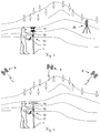
- Figure 1a shows a first embodiment of a survey pole 10 as part of a surveying system according to the invention.
- the survey pole 10 has a rigid, rod-shaped body 13 with a pointer tip 12 for contacting a measuring point on the ground.
- the body 13 defines a pole axis 15.
- the pole 10 comprises retro-reflector means 11 as position giving means for making available the coordinative determination of a referenced position, the retro-reflector means 11 being positioned on the body 13 at a known position relative to the tip 12.
- the system also comprises determination means for repeatedly determining the referenced position of the position giving means.
- the survey pole 10 further comprises an inertial measuring unit 18 placed on the body 13 with a defined spatial relationship relative to the position giving means, wherein the inertial measuring unit 18 is designed in form of a micro-electro-mechanical system and comprises IMU-sensors including accelerometers and gyroscopes.
- the pole 10 comprises evaluation means 17 for deriving the position of the measuring point 1 at least based on the determined referenced position and on the defined spatial relationship of the position giving means relative to the tip 12.
- the inertial measuring unit 18 comprises three accelerometers in a mutually orthogonal configuration, i.e. in a configuration such that their measuring axes are orthogonal to each other, and three gyroscopes in a mutually orthogonal configuration, i.e. in a configuration such that their measuring axes are orthogonal to each other.
- Figure 1b shows a second embodiment of a survey pole 10 as part of a surveying system according to the invention.
- the survey pole 10 has a rigid, rod-shaped body 13 with a pointer tip 12 for contacting a measuring point on the ground.
- the body 13 defines a pole axis 15.
- the pole 10 comprises a GNSS receiver 19 as position giving means for making available the coordinative determination of a referenced position, the GNSS receiver 19 being positioned on the body 13 at a known position relative to the tip 12.
- the system also comprises determination means for repeatedly determining the referenced position of the position giving means.
- the survey pole 10 further comprises an inertial measuring unit 18 placed on the body 13 with a defined spatial relationship relative to the position giving means, wherein the inertial measuring unit 18 is designed in form of a micro-electro-mechanical system and comprises IMU-sensors including accelerometers and gyroscopes.
- the pole 10 comprises evaluation means 17 for deriving the position of the measuring point 1 at least based on the determined referenced position and on the defined spatial relationship of the position giving means relative to the tip 12.
- the inertial measuring unit 18 comprises three accelerometers in a mutually orthogonal configuration, i.e. in a configuration such that their measuring axes are orthogonal to each other, and three gyroscopes in a mutually orthogonal configuration, i.e. in a configuration such that their measuring axes are orthogonal to each other.
- the inertial measuring unit 18 in Figures 1a and 1b is depicted as an external feature of the pole 10, obviously it can also be integrated into the body 13.
- the evaluation means 17, which are depicted in Figures 1a and 1b as an external feature of the pole 10, can also be part of the inertial measuring unit 18 or the GNSS receiver 19, or integrated into the body 13.
- FIG. 2 illustrates the surveying method according to the invention.
- a survey pole 10 is depicted having a body 13 with a pointer tip 12 for contacting the measuring point 1 and a GNSS receiver 19 as position giving means for making available the coordinative determination of a referenced position.
- the GNSS receiver 19 is placed on the body 13 with a defined spatial relationship relative to the tip 12.
- the survey pole 10 further comprises an inertial measuring unit 18 placed on the body 13 with a defined spatial relationship relative to the GNSS receiver 19.
- the inertial measuring unit 18 is designed in form of a micro-electro-mechanical system and comprises IMU-sensors including accelerometers and gyroscopes.
- Evaluation means 17 are provided for deriving the position of the measuring point 1 at least based on the determined referenced position and on the defined spatial relationship of the position giving means relative to the tip 12.
- the data flow is depicted with broken lined arrows:
- the GNSS receiver 19 provides referenced position data and the inertial measuring unit 18 provides inertial state data.
- Referenced Attitude Data for the survey pole 10 is derived.
- This Referenced Attitude Data and referenced position data provided by the GNSS receiver 19 are used for deriving the position of the measuring point 1.
- the position of the inertial measuring unit 18 calculated by the filter may be used. The spatial relationship is then between the CoN of the inertial measuring unit 18 and the tip 12, but the requirement for attitude is unchanged.
- the surveying method according to the invention comprises
- FIG 3 a surveying system comprising the first embodiment of the survey pole 10 (as shown in Figure 1a ) and a total station 20 is depicted.
- the survey pole 10 comprises a rigid, rod-shaped body 13 having a pointer tip 12 for contacting a measuring point 1 on the ground, the body 13 defining a pole axis 15. Retro-reflector means 11 are positioned on the body 13 at a known position relative to the tip 12. A hand-held display and controlling device comprising evaluation means 17 is held by a user operating the pole 10.
- the total station 20 comprises a telescope unit that is adapted for measuring a distance to the retro-reflector 11 of the tilt pole 10.
- the user positions the tip 12 of the survey pole 10 on a measuring point 1, the position of which is to be determined.
- the inertial measuring unit 18 provides inertial state data of the survey pole 10.
- the evaluation means 17 from this data derive Referenced Attitude Data for the survey pole 10.
- the Referenced Attitude Data is then used to derive a position of the measuring point 1.
- FIG 4 a surveying system comprising the second embodiment of the survey pole 10 (as shown in Figure 1b ) is depicted.
- the survey pole 10 comprises a rigid, rod-shaped body 13 having a pointer tip 12 for contacting a measuring point 1 on the ground, the body 13 defining a pole axis 15.
- a GNSS receiver 19 is positioned on the body 13 at a known position relative to the tip 12.
- a hand-held display and controlling device comprising evaluation means 17 is held by a user operating the pole 10.
- the user positions the tip 12 of the survey pole 10 on a measuring point 1, the position of which is to be determined.
- a measuring point 1 By means of satellites 9 and the GNSS receiver 19 referenced position data of the survey pole 10 is provided.
- the evaluation means 17 from this data derive Referenced Attitude Data for the survey pole 10.
- the Referenced Attitude Data is then used to derive a position of the measuring point 1.
- FIG. 5 an upgrade kit 30 for a surveying system is depicted.
- the surveying system comprises a survey pole 10 with a body 13 having a pointer tip 12 for contacting the measuring point 1 and a GNSS-antenna 19 as position giving means for making available the coordinative determination of a referenced position.
- the GNSS-antenna 19 is positioned on the body 13 with a defined spatial relationship relative to the tip 12.
- the system also comprises determination means for repeatedly determining the referenced position of the position giving means and first evaluation means 17 for deriving the position of the measuring point 1 at least based on the determined referenced position and on the defined spatial relationship of the position giving means relative to the tip 12.
- the upgrade kit 30 comprises an inertial measuring unit 38 to be placed on the body 13 of the survey pole 10 with a defined spatial relationship relative to the position giving means, wherein the inertial measuring unit 38 comprises IMU-sensors including accelerometers and gyroscopes, IMU-processing means for repeatedly determining inertial state data based on measurements taken by the inertial measuring unit, and second evaluation means 37.
- the second evaluation means 37 are configured for receiving the repeatedly determined referenced position and the repeatedly determined inertial state data, feeding a predefined filter algorithm with the repeatedly determined referenced position and the repeatedly determined inertial state data and deriving therefrom referenced attitude data for the survey pole 10.
- a Divided Difference Filter is used within the predefined filter algorithm, and the defined spatial relationship of the inertial measuring unit 38 relative to the position giving means is taken into account.
- the referenced attitude data is used for deriving the position of the measuring point 1.
- the upgrade kit 30 comprises attaching means 33 for attaching the upgrade kit 30 to the body 13 of the survey pole 10. Although the upgrade kit 30 in Figure 5 is depicted attached to the body 13 in the middle section of the pole 10, obviously it is also possible to attach it next to the position giving means or near the tip 12.
- FIG. 6 shows a surveying module 40 for a surveying system.
- the surveying system comprises a survey pole 10 with a body 13 having a pointer tip 12 for contacting the measuring point 1.
- the surveying module 40 comprises a GNSS-antenna 49 as position giving means for making available the coordinative determination of a referenced position, wherein the GNSS-antenna 49 is to be placed on the body 13 of the survey pole 10 with a defined spatial relationship relative to the tip 12.
- the surveying module 40 also comprises determination means for repeatedly determining the referenced position of the position giving means and evaluation means 37 for deriving the position of the measuring point 1 at least based on the determined referenced position and on the defined spatial relationship of the position giving means relative to the tip 12.
- the surveying module 40 comprises an inertial measuring unit 48 that is to be placed on the body 13 of the survey pole 10 with a defined spatial relationship relative to the position giving means, wherein the inertial measuring unit 48 comprises IMU-sensors including accelerometers and gyroscopes, and IMU-processing means for repeatedly determining inertial state data based on measurements taken by the inertial measuring unit.
- the inertial measuring unit 48 comprises IMU-sensors including accelerometers and gyroscopes, and IMU-processing means for repeatedly determining inertial state data based on measurements taken by the inertial measuring unit.
- the evaluation means 47 are configured for receiving the repeatedly determined referenced position and the repeatedly determined inertial state data, feeding a predefined filter algorithm with the repeatedly determined referenced position and the repeatedly determined inertial state data and deriving therefrom referenced attitude data for the survey pole 10. For this purpose a Divided Difference Filter is used within the predefined filter algorithm, and the defined spatial relationship of the inertial measuring unit 48 relative to the position giving means is taken into account. The referenced attitude data is used for deriving the position of the measuring point 1.
- the evaluation means 47 and the inertial measuring unit 48 of the surveying module 40 can be integrated into the GNSS receiver 49.
- the surveying module 40 can be in a two-part form, for instance one part comprising the position-giving means and the other one comprising the inertial measuring unit 48.
- the surveying module 40 comprises attaching means 43 for attaching the surveying module 40 to the body 13 of the survey pole 10.
- the attaching means 43 can also be adapted to screw the surveying module 40 onto the top end of the survey pole 10.
Landscapes
- Engineering & Computer Science (AREA)
- Radar, Positioning & Navigation (AREA)
- Remote Sensing (AREA)
- Physics & Mathematics (AREA)
- General Physics & Mathematics (AREA)
- Automation & Control Theory (AREA)
- Electromagnetism (AREA)
- Navigation (AREA)
- Position Fixing By Use Of Radio Waves (AREA)
Description
- The invention pertains to a surveying system and a surveying method for measuring the position of a point on the ground with the help of a survey pole. It also pertains to an upgrade kit and a surveying module for such a surveying system and to a computer programme product for executing steps of such a surveying method.
- In survey applications using GNSS equipment, the measurement taken by the GNSS receiver does not directly correspond to the target point to be surveyed; rather, it is a position measurement of the so-called "phase-centre" of the GNSS antenna. Current practice is to mount the antenna on a pole and ensure the pole is perfectly vertical over the point of interest and compensate the position for the length of the pole. Levelling the pole, however, takes time and it would be desirable to take measurements of the target position without the need to level the pole.
- In this document, a method is detailed for the accurate compensation of the tilt of the pole using a fusion of relatively low-cost inertial sensors (accelerometers and gyroscopes) and GNSS measurements. It has advantages over other disclosed methods as the inertial sensors are of substantially lower cost and sensor errors are explicitly estimated at run-time.
- Global Navigation Satellite Systems (GNSS), such as the NAVSTAR Global Positioning System (GPS) are now routinely used in surveying applications with the use of Real-Time Kinematic (RTK) algorithms, which correct for a receiver's position using information from one or more nearby base station(s).
- The position measured by the GNSS receiver is at the so-called "phase centre" of the GNSS antenna, which for a high-quality survey antenna is a well-quantified location generally near the mechanical centre of the antenna. However, the location of interest to the surveyor is not at the antenna, but at a point on the ground; the antenna is usually mounted on a pole to optimise the reception of GNSS signals.
- Unless the pole is perfectly upright with respect to the ground, the horizontal position of the antenna will be offset compared to the location on the ground of interest. A levelling device, whether a traditional spirit level or a more sophisticated arrangement of sensors, can be used to determine if a pole is upright to some degree of tolerance sufficient to take a measurement. Alternatively, if one can precisely measure the angular orientation (the "attitude") of the pole, this error can be compensated for, assuming one knows the length of the pole.
- Measuring the angle of the pole with respect to the ground is not a trivial exercise. Whilst measuring the angle of the pole from the vertical (the pitch and roll) can be accurately achieved through a number of methods (notably, measurement of local gravity using accelerometers or inclinometers), measuring the orientation of the pole with respect to True North (the yaw or azimuth) is considerably more difficult.
- The most obvious way to achieve a measurement of azimuth is with the use of an electronic compass, which is able to measure orientation with respect to Magnetic North. However, aside from the offset between Magnetic North and True North, the compass reading can also be affected by magnetic field disturbances such as ferrous metals and electric currents, both of which are common around some building sites. To avoid these drawbacks, another method of determining the yaw is desirable.
- When installed in a conventional land vehicle such as a car, the azimuth angle is able to be inferred from the GNSS velocity, since the vehicle is normally aligned with the direction of travel. However, since a pole-mounted antenna may move in an arbitrary direction, GNSS velocity is not a reliable means of azimuth determination.
- When stationary, high-grade inertial sensors are capable of measuring the Earth's rotation rate, which may then be used for finding north. When using high-quality gyroscopes ("gyros"), a procedure known as "gyro compassing" can be used whilst stationary to determine north by comparing the measured rotation rate in each axis.
- Once an initial position and attitude is known, a high-quality INS can navigate without reference to GNSS or other external measurements, making it useful for survey applications when GPS is unavailable. This is described, for instance in
US 2009 024 325 A1 which describes an INS used in a surveying application with a GNSS solution being unavailable. However, as an inertial navigation solution mathematically rotates and integrates the raw inertial sensor measures, small errors will accumulate and the position solution (and azimuth solution, which must be maintained as a by-product) will drift without bound. - The drift problem of an INS has been studied extensively for some time. The drift in the position and attitude solution (and thereby the means to compensate for pole tilt) can be contained by intelligently fusing GNSS or other external measurements with an inertial navigation system - the so-called "Aided Inertial Navigation System" (AINS) - which has long existed in the aerospace industry and is now used in surveying applications.
- Whilst high-quality "navigation grade" and "tactical grade" inertial sensors - navigation grade refers to sensors that can be useful for standalone navigation for many hours, e.g. including Ring Laser Gyroscopes (RLG), whereas tactical grade generally refers to navigation requirements for short flights, e.g. including Fibre Optic Gyroscopes (FOG) - are undoubtedly useful in determining position and attitude (whether GNSS aided or otherwise), they are also very expensive, heavy, bulky and suffer from high power consumption. In contrast, the last decade or so has seen the rise of inertial sensors based on MEMS (Micro-Electro-Mechanical Sensors) technology, which have substantially lower performance in comparison with traditional high-grade devices, but have the advantage of being small, low-power lightweight, and more than an order of magnitude less expensive than high-grade inertial sensors. MEMS inertial sensors are now routinely integrated into low-accuracy consumer applications such as games console controllers and mobile phones. MEMS sensors are normally of "consumer grade" or "industrial grade", though some high-end silicon MEMS may also be considered as tactical grade. Consumer grade refers to cheap sensors having coarse motion sensing for applications such as shock detection, free-fall detection, mobile phones or computer games controllers. Industrial grade refers to sensors that are useful for applications where some degree of motion sensing precision is required, such as manufacturing robots, machine control, automotive electronic stability, hill-start assistance and entry-level Attitude and Heading Reference Systems (AHRS).
- MEMS sensors, like many integrated circuit technologies, have substantially improved in performance over time. Although they presently remain unsuitable for standalone inertial navigation, they may be fused with GNSS measurements in a similar fashion to a high-grade AINS solution to maintain an attitude solution of sufficient accuracy to compensate for the tilt of a survey pole. Furthermore, the combination of GNSS and INS is greater than the sum of its parts - intelligent integration of the two allow for the most substantial errors that exist in MEMS inertial sensors to be estimated and removed.
- The drawback of using MEMS devices is that it relies on a good-quality GNSS solution to be available, which is generally the case for many surveying and related activities such as stake-out. Usually, more than a few seconds without a GNSS solution will cause the attitude to drift out of tolerance, depending on the grade of sensor. Generally, a high-quality position is required survey applications and therefore attitude drift during GNSS outages is usually not problematic. Once a GNSS reacquired, a smaller drift will speed up re-convergence of the attitude solution. It is up to the designer to make the trade-off between stability and cost.
- Attitude may be interpreted as a combination of three different rotations - roll, which (when related to an aircraft) is "wings up, wings down"; pitch, which is "nose up, nose down" and yaw, which corresponds to the heading that the platform is pointing. Classically, pitch and roll are observed through measurements of the local gravity vector (which induce an acceleration measurement on the accelerometers) and yaw is observed through the use of a magnetic compass.
- Whilst in prior art - for example in
US 2003 046 003 A1 ,US 5,512,905 A ,EP 2 040 029 A1 ,EP 1 726 915 A1JP 2005 043 088 A - When inertial sensor measurements are intelligently combined with GPS, both the yaw angle (even without the aid of a magnetic compass) and sensor errors causing the errors in pitch and roll may be estimated when subjected to particular motion conditions. In particular yaw angle, generally considered to be the hardest to estimate, has been shown in the academic literature to converge towards its true value when the inertial sensors are subjected to changes in acceleration in the horizontal plane, which is often the case during a surveying operations. The situation is further complicated for MEMS devices, which have significant errors compared to high-grade devices. In high-grade sensors, bias errors on the vertical gyro are naturally observable through the rotation of the Earth. In MEMS devices, the signal caused the Earth's rotation is buried in noise and bias. Therefore, MEMS will require more aggressive manoeuvring to make yaw observable, but the basic fact that it is observable under motion is unchanged.
- With this observation in mind, it can be noted that a magnetic compass is not strictly necessary for the estimation of yaw (and therefore can be removed if cost is a concern), but may still be used for a coarse initialisation of yaw or to provide supplementary measurements if the yaw has drifted due to the lack of motion for some time.
- The notation used in this document is as follows:
An identity matrix of size k is denoted by Ik . The rotation matrix from the a-frame to the b-frame is denoted by

- [A]× is a skew-symmetric matrix constructed from vector A such that when multiplied by vector B the result is equivalent to the cross-product of A and B, viz [A]×B = A×B.
- Time derivatives of a quantity are expressed using the dot notation (e.g.


- In this document, the b-frame is the body fixed frame, the n-frame is an earth-fixed local tangent frame (north, east, down), the e-frame is the Earth-Centred Earth-Fixed (ECEF) frame and the i-frame is the Earth-Centred Inertial (ECI) frame.
- The GPS/INS estimates a position at the reference point of INS,


- Key to the accurate compensation of tilt is the attitude estimate. Clearly, any errors in attitude will couple onto errors at the ground point.
- The observation of attitude and sensor errors relies on comparing the difference between the GPS position and the INS position. GPS velocity may also be used. Under motion, position errors coupled in from attitude errors can be indirectly separated. Note that an INS must maintain an accurate representation of attitude as a by-product of calculating a position solution.
- Integrated GPS/INS navigation systems have long been used in the aerospace domain, owing the complementary characteristics of the two navigation sources. As such, multiple textbooks have been published on the subject which recommend a so-called loosely-coupled error-state system, for instance Robert M. Rogers: Applied Mathematics in Integrated Navigation Systems. AIAA Education, 3rd edition, 2007.
- There are several components in the integration architecture:
- 1. An Inertial Measurement Unit (IMU), comprising three accelerometers, three gyroscopes in a nominally orthogonal configuration, associated support circuitry for signal acquisition, pre-processing, time synchronisation and deterministic error removal;
- 2. The Inertial Navigation System (INS) mechanisation, which mathematically rotates and integrates the accelerations and rotation rate measurements from the IMU to estimate the position and attitude;
- 3. A GPS receiver, measuring position and velocity of the antenna;
- 4. A Kalman Filter, which estimates the errors of position, errors in velocity, errors in attitude, gyro biases and accelerometer biases, based on the error dynamics of the system and observed difference between the GPS and INS positions; and
- 5. Optionally, a two- or three-axis magnetometer for measuring the Earth's magnetic field.
- The key feature of the classic loosely-coupled error-state estimator is the linearization of the dynamics, which allows the use of a linear Kalman Filter. The major drawback of using such an architecture is the assumption that the errors are small and hence the error introduced by linearization is negligible. Whilst this might be true using high-quality sensors and a specific initialisation procedure, surveying applications (and especially construction surveying) is significantly more cost sensitive than the aerospace domain and hence estimation methods designed for high-quality sensors are not necessarily applicable to lower-cost MEMS inertial sensors described in the introduction. In particular, the small error assumption results in poor performance when using low-cost sensors. It is inherently clear that a better estimator is required for use with low-cost sensors.
- In particular, the standard methods of GPS/INS integration, as for instance disclosed in
US 2009 024 325 A1 , have insufficient performance to reliably determine the attitude of the pole when using industrial-grade sensors. Therefore, these methods are fundamentally not viable for industrial grade sensors. - It is therefore an object of the present invention to provide an improved surveying system and an improved surveying method for measuring the position of a measuring point on the ground.
- It is another object of the present invention to provide such a surveying system and such a surveying method for quickly, reliably and precisely measuring the position of a measuring point on the ground.
- A further object of the invention is to provide such a surveying system at lower costs.
- At least one of these objects is achieved by the surveying system according to
Claim 1, the upgrade kit according to claim 8, the survey module according toclaim 10, the surveying method according toClaim 11 and/or the dependent claims of the present invention. - According to the invention a surveying system for measuring the position of a measuring point on the ground comprises a survey pole. The survey pole comprises a body having a pointer tip for contacting the measuring point and position giving means for making available the coordinative determination of a referenced position. The position giving means - e.g. a GNSS receiver, such as a GPS antenna, or a retro-reflector for use with a total station - are placed on the body of the survey pole with a defined spatial relationship relative to the tip. The survey pole further comprises an inertial measuring unit that is placed on the body with a defined spatial relationship relative to the position giving means and is designed in form of a micro-electro-mechanical system and comprises IMU-sensors including accelerometers and gyroscopes.
- The surveying system comprises determination means for repeatedly determining the referenced position of the position giving means and IMU-processing means for repeatedly determining inertial state data based on measurements taken by the inertial measuring unit. The surveying system furthermore comprises evaluation means for deriving the position of the measuring point at least based on the determined referenced position and on the defined spatial relationship of the position giving means relative to the tip. The evaluation means are also configured for feeding a predefined filter algorithm with the repeatedly determined referenced position and the repeatedly determined inertial state data and deriving therefrom referenced attitude data for the survey pole, taking into account the defined spatial relationship of the inertial measuring unit relative to the position giving means, and for using the referenced attitude data for deriving the position of the measuring point.
- According to the invention, the evaluation means are configured for using a Divided Difference Filter (DDF) within the predefined filter algorithm.
- Preferably, the inertial measuring unit is designed in form of a micro-electro-mechanical system and comprises IMU-sensors including accelerometers and gyroscopes.
- In a preferred embodiment the inertial measuring unit comprises three accelerometers in a mutually orthogonal configuration and three gyroscopes in a mutually orthogonal configuration.
- In one embodiment the inertial measuring unit comprises inertial sensors of "tactical grade" or lower, i.e. typically having
- a gyro bias stability of > 0.1 deg/hr,
- a gyro scale factor of > 10 ppm,
- a gyro noise of > 0.01 deg/rtHr,
- an accelerometer bias stability of > 0.1 mg,
- an accelerometer scale factor of > 100 ppm and
- an accelerometer noise of > 20 ug/rtHz.
- In a preferred embodiment, the inertial sensors are of "industrial grade" or "automotive grade", i.e. typically having
- a gyro bias stability of > 1 deg/hr,
- a gyro scale factor of > 1000 ppm,
- a gyro noise of > 1 deg/rtHr,
- an accelerometer bias stability of > 1 mg,
- an accelerometer scale factor of > 1000 ppm and
- an accelerometer noise of > 100 ug/rtHz.
- In another preferred embodiment the IMU-processing means are configured for determining inertial position data and inertial attitude data as part of the inertial state data, particularly also inertial velocity data and IMU-sensor error parameters.
- In a further preferred embodiment the inertial measuring unit further comprises at least one magnetometer, particularly two or three magnetometers in a mutually orthogonal configuration, and the IMU-processing means are configured for determining also compass-attitude data as part of the inertial state data.
- Preferably, the IMU-processing means are configured for repeatedly determining the inertial state data with a higher rate than the determination means the referenced position, and the evaluation means are configured for feeding the predefined filter algorithm with the repeatedly determined inertial state data with a higher rate than with the repeatedly determined referenced position.
- In a preferred embodiment the position giving means comprise a retro reflector, and the determination means comprise a total station or a tacheometer for measuring the referenced position of the retro reflector.
- In another preferred embodiment the position giving means comprise a GNSS-antenna, in particular a GPS receiver, and the determination means comprise a GNSS-processing unit for processing output-signals of the GNSS-antenna and deriving therefrom the referenced position of the GNSS-antenna.
- In another preferred embodiment the evaluation means are further configured for deriving referenced attitude data, which for example can be represented by a referenced yaw angle, i.e. a referenced heading or azimuth angle, as well as a referenced pitch angle and a referenced roll angle, i.e. referenced tilt angles, of the survey pole.
- Another aspect of the invention is an upgrade kit for a surveying system, the upgrade kit being adapted for detecting attitude data, the surveying system comprising a survey pole with a body having a pointer tip for contacting the measuring point and position giving means for making available the coordinative determination of a referenced position, the position giving means being placed on the body with a defined spatial relationship relative to the tip, particularly wherein the position giving means comprise a retro reflector and/or a GNSS-antenna, determination means for repeatedly determining the referenced position of the position giving means and first evaluation means for deriving the position of the measuring point at least based on the determined referenced position and on the defined spatial relationship of the position giving means relative to the tip. According to the invention the upgrade kit comprises an inertial measuring unit to be placed on the body with a defined spatial relationship relative to the position giving means, wherein the inertial measuring unit comprises IMU-sensors including accelerometers and gyroscopes, IMU-processing means for repeatedly determining inertial state data based on measurements taken by the inertial measuring unit, and second evaluation means configured for feeding a predefined filter algorithm with the repeatedly determined referenced position and the repeatedly determined inertial state data and deriving therefrom referenced attitude data for the survey pole, taking into account the defined spatial relationship of the inertial measuring unit relative to the position giving means, using a Divided Difference Filter within the predefined filter algorithm, and further using the referenced attitude data for deriving the position of the measuring point.
- Preferably, the upgrade kit comprises means for attaching the upgrade kit or parts thereof, in particular the inertial measuring unit, to the survey pole.
- In a preferred embodiment the upgrade kit comprises means for detecting and/or defining a spatial relationship of the inertial measuring unit relative to the position giving means.
- Another aspect of the invention is a surveying module for a surveying system, the surveying module being adapted for detecting attitude data, the surveying system comprising a survey pole with a body having a pointer tip for contacting the measuring point. The surveying module comprises position giving means for making available the coordinative determination of a referenced position, wherein the position giving means are to be placed on the body with a defined spatial relationship relative to the tip, particularly wherein the position giving means comprise a retro reflector and/or a GNSS-antenna, determination means for repeatedly determining the referenced position of the position giving means and evaluation means for deriving the position of the measuring point at least based on the determined referenced position and on the defined spatial relationship of the position giving means relative to the tip. According to this aspect of the invention the surveying module further comprises an inertial measuring unit to be placed on the body with a defined spatial relationship relative to the position giving means, wherein the inertial measuring unit comprises IMU-sensors including accelerometers and gyroscopes, and IMU-processing means for repeatedly determining inertial state data based on measurements taken by the inertial measuring unit. The evaluation means are configured for receiving the repeatedly determined referenced position and the repeatedly determined inertial state data, feeding a predefined filter algorithm with the repeatedly determined referenced position and the repeatedly determined inertial state data and deriving therefrom referenced attitude data for the survey pole, taking into account the defined spatial relationship of the inertial measuring unit relative to the position giving means, using a Divided Difference Filter within the predefined filter algorithm, and using the referenced attitude data for deriving the position of the measuring point.
- The surveying method according to the invention comprises
- repeatedly determining the referenced position of the position giving means,
- deriving the position of the measuring point at least based on the determined referenced position and on the defined spatial relationship of the position giving means, e.g. a retro reflector or a GNSS receiver, relative to the tip,
- repeatedly determining inertial state data based on measurements taken by the inertial measuring unit and
- feeding a predefined filter algorithm with the repeatedly determined referenced position and the repeatedly determined inertial state data and deriving therefrom referenced attitude data for the survey pole, taking into account the defined spatial relationship of the inertial measuring unit relative to the position giving means, and
- further using the referenced attitude data for deriving the position of the measuring point.
- In a preferred embodiment of the method according to invention a Divided Difference Filter (DDF) is used within the predefined filter algorithm.
- In another preferred embodiment of the method referenced attitude data is derived, which for example can be represented by a referenced yaw angle, i.e. a referenced heading or azimuth angle, as well as a referenced pitch angle and a referenced roll angle, i.e. referenced tilt angles, of the survey pole.
- In another preferred embodiment inertial position data and inertial attitude data are determined as part of the inertial state data, preferably also inertial velocity data and IMU-sensor error parameters, especially wherein the IMU-sensor error parameters are determined based on an error model for the IMU-sensors including at least one of
- sensor-bias,
- sensitivity errors,
- misalignment and
- non-linearity errors,
- as well as - as regards the gyroscopes - acceleration sensitivity.
- The process of inertial navigation is to take the specific force and angular rate measurements, correct for any errors, and integrate the sensors as required to produce a position, velocity and attitude solution with respect to a reference frame. The INS mechanisation may be performed in any number of reference frames, but a convenient choice is the Earth-Centred, Earth-Fixed (ECEF) frame as it is the natural coordinate system for GPS.
- Since the inertial measurements are taken with respect to inertial space, a correction for the Earth's rotation rate is required. The INS mechanisation equations in the ECEF frame may be stated as:


- Since there will always be a lever arm between the Centre of Navigation (CoN) of the IMU and the GPS antenna, the observation equations relating the position of the GPS antenna must take this into account, i.e.


- The INS mechanisation and observation equations have assumed perfect knowledge of the specific force and angular rate measurements. However, inertial sensors contain a number of errors that need to be accounted for.
- For a triad of accelerometers, the specific force measurement


- A triad of gyroscopes will exhibit similar errors to the accelerometers, but will have an additional error induced by accelerations. Therefore, a measurement model for the body angular rate measurements


- Not all terms may be significant and may be accumulated in the white noise and time-varying bias terms. Others, such as non-linearity might be suitable for production measurement and compensation, but not for online estimation. Some errors may be adequately modelled as a random constant whereas others may be consistent with a Gauss-Markov process or a Random Walk.
- Bias is an offset on each of the sensors and consists of a number of difference components:

- The scale factor and misalignment matrix (SFA) Sa represents two common errors on the sensors; scale factor (sometimes called sensitivity errors) and cross-axis-sensitivity errors (sometimes called misalignments). The cross-axis-sensitivity errors are a combination of non-orthogonal mounting (i.e. the sensors not perfectly mounted 90°) and instrument sensitivity to orthogonal acceleration components. Thus, the errors may be written as:

- The zeroth and first order error effects are accounted for in the bias and SFA components respectively. However, since MEMS devices typically have non-linearity in the order of 1%, it is worth describing the error model, at least for factory calibration purposes. The error model, including non-linear cross-coupling is as follows:


- Generally, these errors will be small compared to white noise in the current generation of MEMS devices, or may be incorporated into a random-walk bias component unless there is compelling evidence that they should be individually modelled.
- Of the possible error sources from the inertial sensors, some will be need to be estimated online whereas others are stable and small enough to be ignored or measured and compensated in production. Each error term becomes an additional state in the filter and hence increases the computational requirement to estimate online. The bias terms will almost always be estimated online. The scale factor and misalignment terms are sometimes estimated online. Other terms are only rarely estimated online. The selection of instrument errors to estimate online is an engineering trade-off between sensor quality, computational resources and desired system accuracy.
- The INS mechanisation equations and the GNSS measurements together constitute a process and measurement model in the following form:
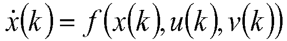

- The estimation task is to infer the state vector x(t), given a set of noisy measurements y(k), y(k-1), ... , y(k-n). For a general non-linear function, a general optimal estimate for x(t) is not possible and hence suboptimal filters are of interest. As noted previously, a linearised approximation can perform poorly with low-cost sensors and more sophisticated schemes are desirable.
- The estimator adopted for this task is the Divided Difference Filter (DDF), first published by Norgaard (M. Norgaard, N. Poulsen, O. Ravn: "New developments in state estimation for nonlinear systems." Automatica, 36 (11): 1627-1638, 2000) and shown to have superior performance to the (linearised) Extended Kalman Filter (EKF). Conceptually, the principle underlying the DDF resembles that of the EKF and its higher-order relatives. The implementation is, however, quite different. The major difference between the DDF and the EKF is that the DDF recovers the mean and covariance from a number of samples propagated through the full non-linear dynamics of the system. The samples are selected based on Stirling's interpolation formula which is conceptually similar to Taylor's approximation, but with very different results. Furthermore, these samples may take into account the non-linear dynamics of how process noise propagates through the system. Compared to this, the EKF propagates a single sample through the non-linear dynamics with zero noise to estimate the mean, and the covariance propagated via a linearization of the state dynamics.
- For reasons of computational efficiency and numerical stability, the covariance matrices are implemented in terms of their Cholesky factors rather than symmetric matrices, i.e.


- The a priori update is then performed as follows.
- Let the jth column of matrix Sx be denoted Sx,j. Four "divided difference" matrices are then constructed as:


- The predicted mean, x(k+1|k), may then be calculated as:

- The predicted covariance Cholesky factor is then calculated as:

- Let
S x = Sx (k+1|k),x = x(k+1|k) andw = E[w(k+1)]. A set of four matrices are defined with the columns being:


- The predicted measurement is given as:

- With the predicted measurement covariance factor (note that it is not triangularised) given by:

- The cross-covariance of the measurements and the states is given by:

- With the Kalman Gain calculated as:

- The state vector is then updated as:

- With the state Cholesky factor updated as:

- A key component of the GPS/INS filter is the estimation of attitude. The implicit assumption of the DDF is that the variables in the state vector belong to vector space (additive, scaling and other mathematical operations apply). However, attitude does not belong in vector space since it can be quite easily shown that attitude angles are not additive. Rather, attitude belongs to the special orthogonal group and thus vector operations that underpin the DDF cannot be directly used.
- Furthermore, some attitude representations are double-cover (more than one numerical value for the same attitude) which is problematic for a filter where points are weighted and averaged. For example, the arithmetic mean of rotation vectors [π 0 0] and [-π 0 0] (which represent the same rotation) results in [0 0 0], whereas the true angle average should result in either [π 0 0] or [-π 0 0].
- The direct representation of attitude as a state in a DDF is therefore problematic. The solution of the present invention has been adapted from spacecraft navigation literature originally developed for a different estimation filter: J. Crassidis, F. Markley: "Unscented filtering for spacecraft attitude estimation. Journal of Guidance Control and Dynamics, 26 (4): 536, 2003. Whilst large angles are not additive, small angles denoted in a three-parameter representation are approximately additive. Therefore representing the attitude state as a deviation from a nominal attitude (i.e. an error state) will allow it to be applied and the DDF framework can be used with only minor modifications. It is worthwhile noting the difference of this approach to that disclosed in
US 2005 0 251 328 , in which the quaternion attitude is directly used in the state vector. Such a representation is problematic for two reasons: firstly, as discussed, quaternions certainly do not belong in vector space; and secondly, the requirement to maintain unity magnitude of the quaternion makes a weighted average of points difficult to apply. - For technical reasons, the attitude of the pole is maintained as a unit quaternion, which is a four-parameter representation of attitude. Quaternions are discussed in detail in J. A. Farrell, Aided Navigation: GPS with High Rate Sensors. McGraw Hill, 2008, and other attitude representations are discussed in Malcolm D. Shuster, A survey of attitude representations. Journal of the Astronautical Sciences, 41(4): 439-517, 1993.
- For a three-parameter representation of attitude, the Generalised Rodrigues Parameters (GRP) is chosen, which has a simple conversion from a Quaternion based on two parameters a and f which control the location of the singularity in the GRP. All three-parameter representations have a singularity or other ambiguous representation at specific angles. It is up to the designer to ensure that the singular point(s) will not be encountered.
- For a quaternion q = [q 0
q ] T, conversion between a Quaternion and GRP can be achieved as follows:
- Similarly, a Quaternion may be constructed from a GRP as follows:

- To illustrate the implementation of the filter, the state vector for the GNSS/INS filter is chosen as follows:


- The attitude quaternion

- Note that since the attitude error forms part of the state vector, the initial nominal attitude


- From a given a priori attitude error


- The generated error quaternion is used to adjust the nominal attitude quaternion

- The adjusted attitude


- The attitude error that forms the predicted state is generated from the central predicted attitude anomaly

- The calculated


- Since the mean attitude anomaly is used to correct the externally-maintained attitude, it is reset to zero at the end of this operation. Note that since only the mean is altered, the covariance remains unchanged.
- The remaining matter is how to obtain the central predicted quaternion,

- A measurement update may be performed through a similar process. A quaternion anomaly is generated from the GRP for a given state vector

- The attitude used to predict the measurement may then be calculated as:

- The measurement equations for the DDF are calculated


- The quaternion


- The invention in the following will be described in detail by referring to exemplary embodiments that are accompanied by figures, in which:
- Figure 1a
- shows a first embodiment of a survey pole according to the invention;
- Figure 1b
- shows a second embodiment of a survey pole according to the invention;
- Figure 2
- illustrates the surveying method for measuring the position of a measuring point according to the invention;
- Figure 3
- shows a surveying system with the first embodiment of a survey pole according to the invention;
- Figure 4
- shows a surveying system with the second embodiment of a survey pole according to the invention;
- Figure 5
- shows an upgrade kit for a survey system; and
- Figure 6
- shows a surveying module of a surveying system.
-
Figure 1a shows a first embodiment of asurvey pole 10 as part of a surveying system according to the invention. Thesurvey pole 10 has a rigid, rod-shapedbody 13 with apointer tip 12 for contacting a measuring point on the ground. Thebody 13 defines apole axis 15. Thepole 10 comprises retro-reflector means 11 as position giving means for making available the coordinative determination of a referenced position, the retro-reflector means 11 being positioned on thebody 13 at a known position relative to thetip 12. The system also comprises determination means for repeatedly determining the referenced position of the position giving means. Thesurvey pole 10 further comprises aninertial measuring unit 18 placed on thebody 13 with a defined spatial relationship relative to the position giving means, wherein the inertial measuringunit 18 is designed in form of a micro-electro-mechanical system and comprises IMU-sensors including accelerometers and gyroscopes. Thepole 10 comprises evaluation means 17 for deriving the position of themeasuring point 1 at least based on the determined referenced position and on the defined spatial relationship of the position giving means relative to thetip 12. - The
inertial measuring unit 18 comprises three accelerometers in a mutually orthogonal configuration, i.e. in a configuration such that their measuring axes are orthogonal to each other, and three gyroscopes in a mutually orthogonal configuration, i.e. in a configuration such that their measuring axes are orthogonal to each other. -
Figure 1b shows a second embodiment of asurvey pole 10 as part of a surveying system according to the invention. Thesurvey pole 10 has a rigid, rod-shapedbody 13 with apointer tip 12 for contacting a measuring point on the ground. Thebody 13 defines apole axis 15. Thepole 10 comprises aGNSS receiver 19 as position giving means for making available the coordinative determination of a referenced position, theGNSS receiver 19 being positioned on thebody 13 at a known position relative to thetip 12. The system also comprises determination means for repeatedly determining the referenced position of the position giving means. Thesurvey pole 10 further comprises aninertial measuring unit 18 placed on thebody 13 with a defined spatial relationship relative to the position giving means, wherein the inertial measuringunit 18 is designed in form of a micro-electro-mechanical system and comprises IMU-sensors including accelerometers and gyroscopes. Thepole 10 comprises evaluation means 17 for deriving the position of themeasuring point 1 at least based on the determined referenced position and on the defined spatial relationship of the position giving means relative to thetip 12. - The
inertial measuring unit 18 comprises three accelerometers in a mutually orthogonal configuration, i.e. in a configuration such that their measuring axes are orthogonal to each other, and three gyroscopes in a mutually orthogonal configuration, i.e. in a configuration such that their measuring axes are orthogonal to each other. - Although the inertial measuring
unit 18 inFigures 1a and 1b is depicted as an external feature of thepole 10, obviously it can also be integrated into thebody 13. Moreover, the evaluation means 17, which are depicted inFigures 1a and 1b as an external feature of thepole 10, can also be part of the inertial measuringunit 18 or theGNSS receiver 19, or integrated into thebody 13. -
Figure 2 illustrates the surveying method according to the invention. Asurvey pole 10 is depicted having abody 13 with apointer tip 12 for contacting themeasuring point 1 and aGNSS receiver 19 as position giving means for making available the coordinative determination of a referenced position. TheGNSS receiver 19 is placed on thebody 13 with a defined spatial relationship relative to thetip 12. - The
survey pole 10 further comprises aninertial measuring unit 18 placed on thebody 13 with a defined spatial relationship relative to theGNSS receiver 19. Theinertial measuring unit 18 is designed in form of a micro-electro-mechanical system and comprises IMU-sensors including accelerometers and gyroscopes. Evaluation means 17 are provided for deriving the position of themeasuring point 1 at least based on the determined referenced position and on the defined spatial relationship of the position giving means relative to thetip 12. - The data flow is depicted with broken lined arrows: The
GNSS receiver 19 provides referenced position data and the inertial measuringunit 18 provides inertial state data. By feeding this data into a predefined filter algorithm of the evaluation means 17, Referenced Attitude Data for thesurvey pole 10 is derived. This Referenced Attitude Data and referenced position data provided by theGNSS receiver 19 are used for deriving the position of themeasuring point 1. Instead of the referenced position data provided by theGNSS receiver 19, the position of the inertial measuringunit 18 calculated by the filter may be used. The spatial relationship is then between the CoN of the inertial measuringunit 18 and thetip 12, but the requirement for attitude is unchanged. - The surveying method according to the invention comprises
- repeatedly determining the referenced position of the position giving means,
- deriving the position of the
measuring point 1 at least based on the determined referenced position and on the defined spatial relationship of the position giving means, e.g. theretro reflector 11 or theGNSS receiver 19, relative to thetip 12, - repeatedly determining inertial state data based on measurements taken by the inertial measuring
unit 18 and - feeding a predefined filter algorithm with the repeatedly determined referenced position and the repeatedly determined inertial state data and deriving therefrom referenced attitude data for the
survey pole 10, taking into account the defined spatial relationship of the inertial measuringunit 18 relative to the position giving means, and - further using the referenced attitude data for deriving the position of the
measuring point 1. - In
Figure 3 a surveying system comprising the first embodiment of the survey pole 10 (as shown inFigure 1a ) and atotal station 20 is depicted. - The
survey pole 10 comprises a rigid, rod-shapedbody 13 having apointer tip 12 for contacting ameasuring point 1 on the ground, thebody 13 defining apole axis 15. Retro-reflector means 11 are positioned on thebody 13 at a known position relative to thetip 12. A hand-held display and controlling device comprising evaluation means 17 is held by a user operating thepole 10. - The
total station 20 comprises a telescope unit that is adapted for measuring a distance to the retro-reflector 11 of thetilt pole 10. - The user positions the
tip 12 of thesurvey pole 10 on ameasuring point 1, the position of which is to be determined. By means of thetotal station 20 and the retro-reflector 11 referenced position data of thesurvey pole 10 is provided. Theinertial measuring unit 18 provides inertial state data of thesurvey pole 10. The evaluation means 17 from this data derive Referenced Attitude Data for thesurvey pole 10. The Referenced Attitude Data is then used to derive a position of themeasuring point 1. - In
Figure 4 a surveying system comprising the second embodiment of the survey pole 10 (as shown inFigure 1b ) is depicted. - The
survey pole 10 comprises a rigid, rod-shapedbody 13 having apointer tip 12 for contacting ameasuring point 1 on the ground, thebody 13 defining apole axis 15. AGNSS receiver 19 is positioned on thebody 13 at a known position relative to thetip 12. A hand-held display and controlling device comprising evaluation means 17 is held by a user operating thepole 10. - The user positions the
tip 12 of thesurvey pole 10 on ameasuring point 1, the position of which is to be determined. By means ofsatellites 9 and theGNSS receiver 19 referenced position data of thesurvey pole 10 is provided. The evaluation means 17 from this data derive Referenced Attitude Data for thesurvey pole 10. The Referenced Attitude Data is then used to derive a position of themeasuring point 1. - In
Figure 5 anupgrade kit 30 for a surveying system is depicted. The surveying system comprises asurvey pole 10 with abody 13 having apointer tip 12 for contacting themeasuring point 1 and a GNSS-antenna 19 as position giving means for making available the coordinative determination of a referenced position. The GNSS-antenna 19 is positioned on thebody 13 with a defined spatial relationship relative to thetip 12. - The system also comprises determination means for repeatedly determining the referenced position of the position giving means and first evaluation means 17 for deriving the position of the
measuring point 1 at least based on the determined referenced position and on the defined spatial relationship of the position giving means relative to thetip 12. Theupgrade kit 30 comprises aninertial measuring unit 38 to be placed on thebody 13 of thesurvey pole 10 with a defined spatial relationship relative to the position giving means, wherein the inertial measuringunit 38 comprises IMU-sensors including accelerometers and gyroscopes, IMU-processing means for repeatedly determining inertial state data based on measurements taken by the inertial measuring unit, and second evaluation means 37. - The second evaluation means 37 are configured for receiving the repeatedly determined referenced position and the repeatedly determined inertial state data, feeding a predefined filter algorithm with the repeatedly determined referenced position and the repeatedly determined inertial state data and deriving therefrom referenced attitude data for the
survey pole 10. For this purpose a Divided Difference Filter is used within the predefined filter algorithm, and the defined spatial relationship of the inertial measuringunit 38 relative to the position giving means is taken into account. The referenced attitude data is used for deriving the position of themeasuring point 1. - The
upgrade kit 30 comprises attachingmeans 33 for attaching theupgrade kit 30 to thebody 13 of thesurvey pole 10. Although theupgrade kit 30 inFigure 5 is depicted attached to thebody 13 in the middle section of thepole 10, obviously it is also possible to attach it next to the position giving means or near thetip 12. -
Figure 6 shows asurveying module 40 for a surveying system. The surveying system comprises asurvey pole 10 with abody 13 having apointer tip 12 for contacting themeasuring point 1. The surveyingmodule 40 comprises a GNSS-antenna 49 as position giving means for making available the coordinative determination of a referenced position, wherein the GNSS-antenna 49 is to be placed on thebody 13 of thesurvey pole 10 with a defined spatial relationship relative to thetip 12. The surveyingmodule 40 also comprises determination means for repeatedly determining the referenced position of the position giving means and evaluation means 37 for deriving the position of themeasuring point 1 at least based on the determined referenced position and on the defined spatial relationship of the position giving means relative to thetip 12. - Moreover, the surveying
module 40 comprises aninertial measuring unit 48 that is to be placed on thebody 13 of thesurvey pole 10 with a defined spatial relationship relative to the position giving means, wherein the inertial measuringunit 48 comprises IMU-sensors including accelerometers and gyroscopes, and IMU-processing means for repeatedly determining inertial state data based on measurements taken by the inertial measuring unit. - The evaluation means 47 are configured for receiving the repeatedly determined referenced position and the repeatedly determined inertial state data, feeding a predefined filter algorithm with the repeatedly determined referenced position and the repeatedly determined inertial state data and deriving therefrom referenced attitude data for the
survey pole 10. For this purpose a Divided Difference Filter is used within the predefined filter algorithm, and the defined spatial relationship of the inertial measuringunit 48 relative to the position giving means is taken into account. The referenced attitude data is used for deriving the position of themeasuring point 1. - Alternatively, the evaluation means 47 and the inertial measuring
unit 48 of thesurveying module 40 can be integrated into theGNSS receiver 49. Alternatively, the surveyingmodule 40 can be in a two-part form, for instance one part comprising the position-giving means and the other one comprising the inertial measuringunit 48. - The surveying
module 40 comprises attachingmeans 43 for attaching thesurveying module 40 to thebody 13 of thesurvey pole 10. The attaching means 43 can also be adapted to screw thesurveying module 40 onto the top end of thesurvey pole 10. - Although the invention is illustrated above, partly with reference to some preferred embodiments, it must be understood that numerous modifications and combinations of different features of the embodiments can be made within the scope of the appended claims.
Claims (15)
- Surveying system for measuring the position of a measuring point (1) on the ground, the surveying system comprising• a survey pole (10) with□ a body (13) having a pointer tip (12) for contacting the measuring point (1) and□ position giving means for making available the coordinative determination of a referenced position, the position giving means being placed on the body (13) with a defined spatial relationship relative to the tip (12), particularly wherein the position giving means comprise a retro reflector (11) and/or a GNSS-antenna (19),• determination means for repeatedly determining the referenced position of the position giving means and• evaluation means (17) for deriving the position of the measuring point (1) at least based on the determined referenced position and on the defined spatial relationship of the position giving means relative to the tip (12),wherein• the survey pole (10) further comprises an inertial measuring unit (18) placed on the body (13) with a defined spatial relationship relative to the position giving means, wherein the inertial measuring unit (18) comprises IMU-sensors including accelerometers and gyroscopes, and• the surveying system further comprises IMU-processing means for repeatedly determining inertial state data based on measurements taken by the inertial measuring unit, the inertial state data including an attitude state, wherein• the evaluation means (17) are further configured for▪ feeding a predefined filter algorithm with the repeatedly determined referenced position and the repeatedly determined inertial state data and deriving therefrom referenced attitude data for the survey pole (10), taking into account the defined spatial relationship of the inertial measuring unit (18) relative to the position giving means, and▪ further using the referenced attitude data for deriving the position of the measuring point (1),characterized in that
the evaluation means (17) are further configured for using a Divided Difference Filter within the predefined filter algorithm, and
the attitude state is represented as a deviation from a nominal attitude in a three-parameter representation. - Surveying system according to claim 1,
characterized in that
the inertial measuring unit (18)• is designed in form of a micro-electro-mechanical system and comprises IMU-sensors including accelerometers and gyroscopes and/or• the inertial measuring unit (18) comprises inertial sensors of tactical grade or lower accuracy, in particular of industrial grade or lower accuracy. - Surveying system according to claim 1 or claim 2,
characterized in that• the inertial measuring unit (18) comprises at least three accelerometers in a mutually orthogonal configuration and at least three gyroscopes in a mutually orthogonal configuration,• the IMU-processing means are configured for determining inertial attitude, inertial velocity data and inertial position data as part of the inertial state data, and/or• the evaluation means (17) are further configured for deriving a referenced yaw angle as well as a referenced pitch angle and a referenced roll angle of the survey pole (1) as the referenced attitude data. - Surveying system according to any one of the preceding claims,
characterized in that• the inertial measuring unit (18) further comprises at least one magnetometer, particularly two or three magnetometers in a mutually orthogonal configuration, and in that• the IMU-processing means are configured for determining also compass-attitude data as part of the inertial state data. - Surveying system according to any one of the preceding claims,
characterized in that• the IMU-processing means are configured for repeatedly determining the inertial state data at an equal or a higher rate than the determination means the referenced position and• the evaluation means (17) are configured for feeding the predefined filter algorithm with the repeatedly determined inertial state data with an equal or a higher rate than with the repeatedly determined referenced position. - Surveying system according to any one of the preceding claims, wherein the position giving means comprise a retro reflector (11),
characterized in that
the determination means comprise a total station or a tacheometer for measuring the referenced position of the retro reflector (11). - Surveying system according to any one of the preceding claims, wherein the position giving means comprise a GNSS-antenna (19),
characterized in that
the determination means comprise a GNSS-processing unit for processing output-signals of the GNSS-antenna and deriving therefrom the referenced position of the GNSS-antenna. - Upgrade kit (30) for a surveying system for measuring the position of a measuring point (1) on the ground, the upgrade kit (30) being adapted for detecting attitude data, the surveying system comprising• a survey pole (10) with▪ a body (13) having a pointer tip (12) for contacting the measuring point (1) and▪ position giving means for making available the coordinative determination of a referenced position, the position giving means being placed on the body (13) with a defined spatial relationship relative to the tip (12), particularly wherein the position giving means comprise a retro reflector (11) and/or a GNSS-antenna (19),• determination means for repeatedly determining the referenced position of the position giving means and• first evaluation means (17) for deriving the position of the measuring point (1) at least based on the determined referenced position and on the defined spatial relationship of the position giving means relative to the tip (12),wherein the upgrade kit (30) comprises• an inertial measuring unit (38) to be placed on the body (13) with a defined spatial relationship relative to the position giving means, wherein the inertial measuring unit (38) comprises IMU-sensors including accelerometers and gyroscopes, and• IMU-processing means for repeatedly determining inertial state data based on measurements taken by the inertial measuring unit, the inertial state data including an attitude state, wherein• the upgrade kit (30) further comprises second evaluation means (37) configured for▪ receiving the repeatedly determined referenced position and the repeatedly determined inertial state data,▪ feeding a predefined filter algorithm with the repeatedly determined referenced position and the repeatedly determined inertial state data and deriving therefrom referenced attitude data for the survey pole (10), taking into account the defined spatial relationship of the inertial measuring unit (38) relative to the position giving means, and▪ using the referenced attitude data for deriving the position of the measuring point (1),characterized in that
the second evaluation means (37) are further configured for using a Divided Difference Filter within the predefined filter algorithm, and
the attitude state is represented as a deviation from a nominal attitude in a three-parameter representation. - Upgrade kit (30) according to claim 8,
characterized by• attaching means (33) for attaching the upgrade kit (30) or parts thereof, particularly the inertial measuring unit (38), to the survey pole (10), and/or• means for detecting and/or defining a spatial relationship of the inertial measuring unit (38) relative to the position giving means. - Surveying module (40) for a surveying system for measuring the position of a measuring point (1) on the ground, the surveying module (40) being adapted for detecting attitude data, wherein• the surveying system comprises a survey pole (10) with a body (13) having a pointer tip (12) for contacting the measuring point (1), and• the surveying module (40) comprises▪ position giving means for making available the coordinative determination of a referenced position, wherein the position giving means are to be placed on the body (13) with a defined spatial relationship relative to the tip (12), particularly wherein the position giving means comprise a retro reflector (41) and/or a GNSS-antenna (49),▪ determination means for repeatedly determining the referenced position of the position giving means and▪ evaluation means (47) for deriving the position of the measuring point (1) at least based on the determined referenced position and on the defined spatial relationship of the position giving means relative to the tip (12),wherein the surveying module (40) further comprises• an inertial measuring unit (48) to be placed on the body (13) with a defined spatial relationship relative to the position giving means, wherein the inertial measuring unit (48) comprises IMU-sensors including accelerometers and gyroscopes, and• IMU-processing means for repeatedly determining inertial state data based on measurements taken by the inertial measuring unit, the inertial state data including an attitude state, wherein the evaluation means (47) are configured for• receiving the repeatedly determined referenced position and the repeatedly determined inertial state data,• feeding a predefined filter algorithm with the repeatedly determined referenced position and the repeatedly determined inertial state data and deriving therefrom referenced attitude data for the survey pole (10), taking into account the defined spatial relationship of the inertial measuring unit (48) relative to the position giving means, and• using the referenced attitude data for deriving the position of the measuring point (1),characterized in that
the evaluation means (47) are further configured for using a Divided Difference Filter within the predefined filter algorithm, and
the attitude state is represented as a deviation from a nominal attitude in a three-parameter representation. - Surveying method for measuring the position of a measuring point (1) on the ground, with the help of a survey pole (10) having• a body (13) having a pointer tip (12) for contacting the measuring point (1) and• position giving means for making available the coordinative determination of a referenced position, the position giving means being placed on the body (13) with a defined spatial relationship relative to the tip (12), particularly wherein the position giving means comprise a retro reflector (11) and/or a GNSS-antenna (19),the surveying method comprising• repeatedly determining the referenced position of the position giving means and• deriving the position of the measuring point (1) at least based on the determined referenced position and on the defined spatial relationship of the position giving means relative to the tip (12),wherein the survey pole (10) further comprises an inertial measuring unit placed on the body (13) with a defined spatial relationship relative to the position giving means, wherein the inertial measuring unit comprises IMU-sensors including accelerometers and gyroscopes,
wherein the surveying method further comprises• repeatedly determining inertial state data based on measurements taken by the inertial measuring unit (18), wherein the inertial state data includes an attitude state,• feeding a predefined filter algorithm with the repeatedly determined referenced position and the repeatedly determined inertial state data and deriving therefrom referenced attitude data for the survey pole (10), taking into account the defined spatial relationship of the inertial measuring unit relative to the position giving means, and• further using the referenced attitude data for deriving the position of the measuring point (1),characterized in that• a Divided Difference Filter is used within the predefined filter algorithm, and• the attitude state is represented as a deviation from a nominal attitude in a three-parameter representation. - Surveying method according to claim 11,
characterized in that
the inertial measuring unit (18)• is designed in form of a micro-electro-mechanical system and/or• comprises inertial sensors of tactical grade or lower accuracy, in particular of industrial grade or lower accuracy. - Surveying method according to claim 11 or claim 12,
characterized in that
the referenced attitude data is represented by a referenced yaw angle, a referenced pitch angle and a referenced roll angle of the survey pole (1). - Surveying method according to any one of claims 11 to 13,
characterized in that
inertial position data and inertial attitude data are determined as part of the inertial state data, particularly also inertial velocity data and IMU-sensor error parameters, especially wherein the IMU-sensor error parameters are determined based on an error model for the IMU-sensors including at least one of• sensor-bias,• sensitivity errors,• misalignment and• non-linearity errors,• as well as - as regards the gyroscopes - acceleration sensitivity. - Computer programme product,• comprising programme code which is stored on a machine-readable medium, or being embodied by an electromagnetic wave comprising a programme code segment,• comprising a predefined filter algorithm,• having computer-executable instructions for performing, in particular when run on evaluation means of a survey system according to one of the claims 1 to 7, of an upgrade kit according to one of the claims 8 or 9 or of a survey module according to claim 10, the following steps of the surveying method according to one of the claims 11 to 14:▪ repeatedly determining inertial state data based on measurements taken by the inertial measuring unit (18), wherein the inertial state data includes an attitude state,▪ feeding a predefined filter algorithm with the repeatedly determined referenced position and the repeatedly determined inertial state data and deriving therefrom referenced attitude data for the survey pole (10), taking into account the defined spatial relationship of the inertial measuring unit relative to the position giving means, and▪ further using the referenced attitude data for deriving the position of the measuring point (1),characterized in that• a Divided Difference Filter is used within the predefined filter algorithm, and• the attitude state is represented as a deviation from a nominal attitude in a three-parameter representation.
Priority Applications (1)
| Application Number | Priority Date | Filing Date | Title |
|---|---|---|---|
| EP13776519.4A EP2909579B1 (en) | 2012-10-18 | 2013-10-15 | Surveying system and method |
Applications Claiming Priority (3)
| Application Number | Priority Date | Filing Date | Title |
|---|---|---|---|
| EP12188965.3A EP2722647A1 (en) | 2012-10-18 | 2012-10-18 | Surveying System and Method |
| PCT/EP2013/071548 WO2014060429A1 (en) | 2012-10-18 | 2013-10-15 | Surveying system and method |
| EP13776519.4A EP2909579B1 (en) | 2012-10-18 | 2013-10-15 | Surveying system and method |
Publications (2)
| Publication Number | Publication Date |
|---|---|
| EP2909579A1 EP2909579A1 (en) | 2015-08-26 |
| EP2909579B1 true EP2909579B1 (en) | 2019-05-22 |
Family
ID=47115421
Family Applications (2)
| Application Number | Title | Priority Date | Filing Date |
|---|---|---|---|
| EP12188965.3A Withdrawn EP2722647A1 (en) | 2012-10-18 | 2012-10-18 | Surveying System and Method |
| EP13776519.4A Active EP2909579B1 (en) | 2012-10-18 | 2013-10-15 | Surveying system and method |
Family Applications Before (1)
| Application Number | Title | Priority Date | Filing Date |
|---|---|---|---|
| EP12188965.3A Withdrawn EP2722647A1 (en) | 2012-10-18 | 2012-10-18 | Surveying System and Method |
Country Status (5)
| Country | Link |
|---|---|
| US (1) | US9541392B2 (en) |
| EP (2) | EP2722647A1 (en) |
| CN (1) | CN104736963B (en) |
| BR (1) | BR112015008424B1 (en) |
| WO (1) | WO2014060429A1 (en) |
Cited By (1)
| Publication number | Priority date | Publication date | Assignee | Title |
|---|---|---|---|---|
| EP4194806A1 (en) | 2021-12-09 | 2023-06-14 | Hexagon Technology Center GmbH | Motion-based control for a surveying system |
Families Citing this family (67)
| Publication number | Priority date | Publication date | Assignee | Title |
|---|---|---|---|---|
| IL222221B (en) * | 2012-09-27 | 2019-03-31 | Rafael Advanced Defense Systems Ltd | Improved inertial navigation system and method |
| EP2722647A1 (en) * | 2012-10-18 | 2014-04-23 | Leica Geosystems AG | Surveying System and Method |
| US9821999B2 (en) | 2012-12-28 | 2017-11-21 | Trimble Inc. | External GNSS receiver module with motion sensor suite for contextual inference of user activity |
| US9612341B2 (en) | 2012-12-28 | 2017-04-04 | Trimble Inc. | GNSS receiver positioning system |
| US9538336B2 (en) | 2012-12-28 | 2017-01-03 | Trimble Inc. | Performing data collection based on internal raw observables using a mobile data collection platform |
| US9544737B2 (en) | 2012-12-28 | 2017-01-10 | Trimble Inc. | Performing data collection based on external raw observables using a mobile data collection platform |
| US9880286B2 (en) | 2012-12-28 | 2018-01-30 | Trimble Inc. | Locally measured movement smoothing of position fixes based on extracted pseudoranges |
| US9639941B2 (en) | 2012-12-28 | 2017-05-02 | Trimble Inc. | Scene documentation |
| US9910158B2 (en) | 2012-12-28 | 2018-03-06 | Trimble Inc. | Position determination of a cellular device using carrier phase smoothing |
| US9645248B2 (en) | 2012-12-28 | 2017-05-09 | Trimble Inc. | Vehicle-based global navigation satellite system receiver system with radio frequency hardware component |
| US9602974B2 (en) | 2012-12-28 | 2017-03-21 | Trimble Inc. | Dead reconing system based on locally measured movement |
| US9467814B2 (en) | 2012-12-28 | 2016-10-11 | Trimble Navigation Limited | Collecting external accessory data at a mobile data collection platform that obtains raw observables from an external GNSS raw observable provider |
| US9369843B2 (en) | 2012-12-28 | 2016-06-14 | Trimble Navigation Limited | Extracting pseudorange information using a cellular device |
| US9903957B2 (en) | 2012-12-28 | 2018-02-27 | Trimble Inc. | Global navigation satellite system receiver system with radio frequency hardware component |
| US9945959B2 (en) | 2012-12-28 | 2018-04-17 | Trimble Inc. | Global navigation satellite system receiver system with radio frequency hardware component |
| US9456067B2 (en) | 2012-12-28 | 2016-09-27 | Trimble Navigation Limited | External electronic distance measurement accessory for a mobile data collection platform |
| US9462446B2 (en) | 2012-12-28 | 2016-10-04 | Trimble Navigation Limited | Collecting external accessory data at a mobile data collection platform that obtains raw observables from an internal chipset |
| US10101465B2 (en) | 2012-12-28 | 2018-10-16 | Trimble Inc. | Electronic tape measure on a cellphone |
| US9835729B2 (en) | 2012-12-28 | 2017-12-05 | Trimble Inc. | Global navigation satellite system receiver system with radio frequency hardware component |
| EP2883272B1 (en) * | 2013-08-27 | 2016-06-15 | CommScope Technologies LLC | Alignment determination for antennas and such |
| US11662470B2 (en) | 2014-06-06 | 2023-05-30 | Carlson Software, Inc. | Survey range pole and data collector with electronic height detection, leveling and hands-free data collection |
| WO2015187993A1 (en) | 2014-06-06 | 2015-12-10 | Carlson Software Inc. | Gnss mobile base station and data collector with electronic leveling |
| US10466050B2 (en) * | 2014-06-06 | 2019-11-05 | Carlson Software, Inc. | Hybrid total station with electronic leveling |
| US9923626B2 (en) | 2014-06-13 | 2018-03-20 | Trimble Inc. | Mobile ionospheric data capture system |
| EP2982933B1 (en) * | 2014-08-07 | 2021-03-24 | SALVAGNINI ITALIA S.p.A. | Apparatus and method for measuring a bending angle of a workpiece |
| EP3198303B1 (en) * | 2014-09-26 | 2021-08-04 | Trimble Inc. | External gnss receiver module with motion sensor suite for contextual inference of user activity |
| US9803978B2 (en) * | 2015-02-19 | 2017-10-31 | The United States Of America As Represented By The Secretary Of The Department Of The Interior | Laser rod surface elevation table device and method |
| KR101550403B1 (en) * | 2015-03-03 | 2015-09-18 | 주식회사 디컨스이엔지 | the improved portable prism receiver and the improved portable GPS receiver and the measurement method using the same |
| US10024973B1 (en) | 2015-04-03 | 2018-07-17 | Interstate Electronics Corporation | Global navigation satellite system spoofer identification technique |
| US10031234B1 (en) | 2015-04-03 | 2018-07-24 | Interstate Electronics Corporation | Global navigation satellite system beam based attitude determination |
| SE538872C2 (en) * | 2015-05-04 | 2017-01-17 | Lkab Wassara Ab | Gyro-based surveying tool and method for surveying |
| USD791109S1 (en) | 2015-05-14 | 2017-07-04 | Trimble Inc. | Navigation satellite system antenna |
| JP6630515B2 (en) * | 2015-08-25 | 2020-01-15 | 株式会社トプコン | Position guidance device, position guidance method, program |
| EP3139127B1 (en) * | 2015-09-04 | 2020-02-26 | Leica Geosystems AG | Surveying pole |
| EP3182066B1 (en) * | 2015-12-17 | 2018-07-04 | Leica Geosystems AG | Surveying pole |
| CN108700416B (en) * | 2015-12-30 | 2019-11-22 | 私人基金会加泰罗尼亚电信技术中心 | Improved measuring rod |
| WO2017183001A1 (en) * | 2016-04-22 | 2017-10-26 | Turflynx, Lda. | Automated topographic mapping system" |
| CN105973210B (en) * | 2016-05-19 | 2018-05-22 | 极翼机器人(上海)有限公司 | A kind of surveying instrument bar bottom position filtering method of estimation |
| US10545246B1 (en) | 2016-07-08 | 2020-01-28 | Interstate Electronics Corporation | Global navigation satellite system spoofer identification technique based on carrier to noise ratio signatures |
| US10563980B2 (en) * | 2016-12-23 | 2020-02-18 | Topcon Positioning Systems, Inc. | Enhanced remote surveying systems and methods |
| US10374729B2 (en) * | 2017-02-10 | 2019-08-06 | FreeWave Technologies, Inc. | Antenna alignment tool and method |
| EP3460398A1 (en) * | 2017-09-22 | 2019-03-27 | Trimble Inc. | Methods, apparatuses, and computer programs for estimating the heading of an axis of a rigid body |
| US10876653B2 (en) * | 2017-10-26 | 2020-12-29 | Nicholas Santucci | Laser pipe positioning system |
| US10914054B2 (en) | 2017-11-07 | 2021-02-09 | ModernAg, Inc. | System and method for measurement and abatement of compaction and erosion of soil covering buried pipelines |
| US10725182B2 (en) | 2018-01-04 | 2020-07-28 | Interstate Electronics Corporation | Systems and methods for providing anti-spoofing capability to a global navigation satellite system receiver |
| CN109000630A (en) * | 2018-04-25 | 2018-12-14 | 国家电网公司 | A kind of unmanned plane inspection scale |
| CN109084757B (en) * | 2018-06-25 | 2020-06-02 | 东南大学 | Method for calculating coupling speed error of aircraft wing motion and dynamic deformation |
| CN109269471B (en) * | 2018-11-09 | 2021-07-20 | 上海华测导航技术股份有限公司 | Novel GNSS receiver inclination measuring system and method |
| KR20210099124A (en) * | 2018-12-20 | 2021-08-11 | 에스지 디제이아이 테크놀러지 코., 엘티디 | Positioning method and apparatus based on pose data |
| IL264822A (en) * | 2019-02-13 | 2020-08-31 | Civdrone Ltd | Smart pegs for the construction industry |
| CN110068336A (en) * | 2019-04-25 | 2019-07-30 | 中国人民解放军战略支援部队航天工程大学 | A kind of angular movement measurement method based on magnetic suspension control sensitivity gyro parallel configuration |
| US11194056B2 (en) * | 2019-06-04 | 2021-12-07 | Trimble Inc. | Survey system with field calibration |
| US11536857B2 (en) * | 2019-12-19 | 2022-12-27 | Trimble Inc. | Surface tracking on a survey pole |
| CN113093256B (en) * | 2019-12-23 | 2024-02-13 | 上海华测导航技术股份有限公司 | GNSS/IMU mapping system and method |
| RU2724120C1 (en) * | 2020-01-09 | 2020-06-22 | Максим Владимирович Бушуев | Device for tacheometric observations |
| FR3106403B1 (en) | 2020-01-16 | 2022-02-11 | Agreenculture | Method of geolocation of a target point |
| US11307030B2 (en) * | 2020-02-10 | 2022-04-19 | Joseph Michaud | Laser detector mounting device |
| JP2021128109A (en) * | 2020-02-17 | 2021-09-02 | 株式会社トプコン | Survey machine setting device |
| KR102183142B1 (en) * | 2020-06-24 | 2020-11-26 | 아이씨티웨이주식회사 | History detection system for surveying information in order to correct position of national level point |
| CN112284356B (en) * | 2020-09-29 | 2023-01-24 | 深圳冰河导航科技有限公司 | Wall corner coordinate automatic measurement method based on RTK |
| CN112629526B (en) * | 2020-11-19 | 2023-10-31 | 中国人民解放军战略支援部队信息工程大学 | Tight combination navigation method for Beidou precise single-point positioning and inertial system |
| CN112461071B (en) * | 2020-11-20 | 2023-12-01 | 中国人民解放军63698部队 | Method for measuring repeated installation errors of inertial navigation equipment |
| EP4166901A1 (en) * | 2020-12-11 | 2023-04-19 | Leica Geosystems AG | Surveying pole and secondary sensor unit having toroidal form |
| RU2766052C1 (en) * | 2020-12-25 | 2022-02-07 | Владимир Леонидович Кашин | Method of topographic survey of area and topographic complex means for implementation thereof |
| US20230049084A1 (en) * | 2021-07-30 | 2023-02-16 | Gopro, Inc. | System and method for calibrating a time difference between an image processor and an intertial measurement unit based on inter-frame point correspondence |
| US20230046465A1 (en) * | 2021-07-30 | 2023-02-16 | Gopro, Inc. | Holistic camera calibration system from sparse optical flow |
| US20230351541A1 (en) * | 2022-04-29 | 2023-11-02 | Trimble Inc. | Correcting position of a mobile device using a mobile reference |
Family Cites Families (12)
| Publication number | Priority date | Publication date | Assignee | Title |
|---|---|---|---|---|
| US5512905A (en) | 1994-10-27 | 1996-04-30 | Trimble Navigation Limited | Pole-tilt sensor for surveyor range pole |
| WO2003023557A2 (en) | 2001-09-06 | 2003-03-20 | Wtd Technologies, Inc. | Accident evidence recording method |
| JP4263549B2 (en) | 2003-07-23 | 2009-05-13 | 株式会社トプコン | Survey guidance device |
| US7289906B2 (en) | 2004-04-05 | 2007-10-30 | Oregon Health & Science University | Navigation system applications of sigma-point Kalman filters for nonlinear estimation and sensor fusion |
| EP1726915A1 (en) | 2005-05-27 | 2006-11-29 | Swissat AG | Active surveying pole |
| US20090024325A1 (en) | 2007-07-19 | 2009-01-22 | Scherzinger Bruno M | AINS enhanced survey instrument |
| EP2040029A1 (en) | 2007-09-20 | 2009-03-25 | Swissat AG | A multi mode active surveying pole |
| CA2701529C (en) * | 2007-10-04 | 2017-07-25 | Trusted Positioning Inc. | System and method for intelligent tuning of kalman filters for ins/gps navigation applications |
| EP2264485A1 (en) * | 2009-06-04 | 2010-12-22 | Tracedge | Method for analysing moving object continuous trajectory based on sampled GPS position |
| US10168153B2 (en) * | 2010-12-23 | 2019-01-01 | Trimble Inc. | Enhanced position measurement systems and methods |
| EP2722647A1 (en) * | 2012-10-18 | 2014-04-23 | Leica Geosystems AG | Surveying System and Method |
| US9557157B2 (en) * | 2014-12-01 | 2017-01-31 | Steven Eugene Ihlenfeldt | Inertial dimensional metrology |
-
2012
- 2012-10-18 EP EP12188965.3A patent/EP2722647A1/en not_active Withdrawn
-
2013
- 2013-10-15 EP EP13776519.4A patent/EP2909579B1/en active Active
- 2013-10-15 CN CN201380054683.2A patent/CN104736963B/en active Active
- 2013-10-15 US US14/436,445 patent/US9541392B2/en active Active
- 2013-10-15 WO PCT/EP2013/071548 patent/WO2014060429A1/en active Application Filing
- 2013-10-15 BR BR112015008424-9A patent/BR112015008424B1/en active IP Right Grant
Non-Patent Citations (1)
| Title |
|---|
| None * |
Cited By (1)
| Publication number | Priority date | Publication date | Assignee | Title |
|---|---|---|---|---|
| EP4194806A1 (en) | 2021-12-09 | 2023-06-14 | Hexagon Technology Center GmbH | Motion-based control for a surveying system |
Also Published As
| Publication number | Publication date |
|---|---|
| BR112015008424A2 (en) | 2017-07-04 |
| US20150268045A1 (en) | 2015-09-24 |
| US9541392B2 (en) | 2017-01-10 |
| EP2722647A1 (en) | 2014-04-23 |
| BR112015008424B1 (en) | 2021-01-12 |
| WO2014060429A1 (en) | 2014-04-24 |
| CN104736963B (en) | 2017-11-17 |
| CN104736963A (en) | 2015-06-24 |
| EP2909579A1 (en) | 2015-08-26 |
Similar Documents
| Publication | Publication Date | Title |
|---|---|---|
| EP2909579B1 (en) | Surveying system and method | |
| US6459990B1 (en) | Self-contained positioning method and system thereof for water and land vehicles | |
| US8005635B2 (en) | Self-calibrated azimuth and attitude accuracy enhancing method and system (SAAAEMS) | |
| Fang et al. | Predictive iterated Kalman filter for INS/GPS integration and its application to SAR motion compensation | |
| EP1642089B1 (en) | Method and system for improving accuracy of inertial navigation measurements using measured and stored gravity gradients | |
| CN113203418B (en) | GNSSINS visual fusion positioning method and system based on sequential Kalman filtering | |
| CN201955092U (en) | Platform type inertial navigation device based on geomagnetic assistance | |
| CN113091709A (en) | Novel GNSS receiver inclination measuring method | |
| CN110221332A (en) | A kind of the dynamic lever arm estimation error and compensation method of vehicle-mounted GNSS/INS integrated navigation | |
| EP3460399A1 (en) | Methods, apparatuses, and computer programs for estimating the heading of an axis of a rigid body | |
| RU2768087C2 (en) | Underground mining vehicle and method for its orientation | |
| CN106403952A (en) | Method for measuring combined attitudes of Satcom on the move with low cost | |
| CN103765226A (en) | A method and system of determining an inertial sensor orientation offset | |
| CN105910623B (en) | The method for carrying out the correction of course using magnetometer assisted GNSS/MINS tight integration systems | |
| Sokolović et al. | INS/GPS navigation system based on MEMS technologies | |
| Tomaszewski et al. | Concept of AHRS algorithm designed for platform independent IMU attitude alignment | |
| Mu et al. | Improved decentralized GNSS/SINS/odometer fusion system for land vehicle navigation applications | |
| Maklouf et al. | Performance evaluation of GPS\INS main integration approach | |
| WO2013139486A1 (en) | True north seeking and attitude system | |
| Hansen et al. | Validation and experimental testing of observers for robust gnss-aided inertial navigation | |
| Grochowski et al. | A GPS-aided inertial navigation system for vehicular navigation using a smartphone | |
| US20230349699A1 (en) | Absolute heading estimation with constrained motion | |
| Demkowicz | MEMS Gyro in the Context of Inertial Positionning | |
| Stanisak | „Inertial Technology: Sensors, Algorithms, and Integration,“ | |
| Sun et al. | Analysis of the Kalman filter with different INS error models for GPS/INS integration in aerial remote sensing applications |
Legal Events
| Date | Code | Title | Description |
|---|---|---|---|
| PUAI | Public reference made under article 153(3) epc to a published international application that has entered the european phase |
Free format text: ORIGINAL CODE: 0009012 |
|
| 17P | Request for examination filed |
Effective date: 20150306 |
|
| AK | Designated contracting states |
Kind code of ref document: A1 Designated state(s): AL AT BE BG CH CY CZ DE DK EE ES FI FR GB GR HR HU IE IS IT LI LT LU LV MC MK MT NL NO PL PT RO RS SE SI SK SM TR |
|
| AX | Request for extension of the european patent |
Extension state: BA ME |
|
| DAX | Request for extension of the european patent (deleted) | ||
| STAA | Information on the status of an ep patent application or granted ep patent |
Free format text: STATUS: EXAMINATION IS IN PROGRESS |
|
| 17Q | First examination report despatched |
Effective date: 20170803 |
|
| GRAP | Despatch of communication of intention to grant a patent |
Free format text: ORIGINAL CODE: EPIDOSNIGR1 |
|
| STAA | Information on the status of an ep patent application or granted ep patent |
Free format text: STATUS: GRANT OF PATENT IS INTENDED |
|
| INTG | Intention to grant announced |
Effective date: 20190116 |
|
| RIN1 | Information on inventor provided before grant (corrected) |
Inventor name: DUSHA, DAMIEN |
|
| GRAS | Grant fee paid |
Free format text: ORIGINAL CODE: EPIDOSNIGR3 |
|
| GRAA | (expected) grant |
Free format text: ORIGINAL CODE: 0009210 |
|
| STAA | Information on the status of an ep patent application or granted ep patent |
Free format text: STATUS: THE PATENT HAS BEEN GRANTED |
|
| AK | Designated contracting states |
Kind code of ref document: B1 Designated state(s): AL AT BE BG CH CY CZ DE DK EE ES FI FR GB GR HR HU IE IS IT LI LT LU LV MC MK MT NL NO PL PT RO RS SE SI SK SM TR |
|
| REG | Reference to a national code |
Ref country code: GB Ref legal event code: FG4D |
|
| REG | Reference to a national code |
Ref country code: CH Ref legal event code: EP |
|
| REG | Reference to a national code |
Ref country code: IE Ref legal event code: FG4D |
|
| REG | Reference to a national code |
Ref country code: DE Ref legal event code: R096 Ref document number: 602013055797 Country of ref document: DE |
|
| REG | Reference to a national code |
Ref country code: AT Ref legal event code: REF Ref document number: 1136648 Country of ref document: AT Kind code of ref document: T Effective date: 20190615 |
|
| REG | Reference to a national code |
Ref country code: CH Ref legal event code: NV Representative=s name: KAMINSKI HARMANN PATENTANWAELTE AG, LI |
|
| REG | Reference to a national code |
Ref country code: NL Ref legal event code: FP |
|
| REG | Reference to a national code |
Ref country code: SE Ref legal event code: TRGR |
|
| REG | Reference to a national code |
Ref country code: LT Ref legal event code: MG4D |
|
| PG25 | Lapsed in a contracting state [announced via postgrant information from national office to epo] |
Ref country code: AL Free format text: LAPSE BECAUSE OF FAILURE TO SUBMIT A TRANSLATION OF THE DESCRIPTION OR TO PAY THE FEE WITHIN THE PRESCRIBED TIME-LIMIT Effective date: 20190522 Ref country code: PT Free format text: LAPSE BECAUSE OF FAILURE TO SUBMIT A TRANSLATION OF THE DESCRIPTION OR TO PAY THE FEE WITHIN THE PRESCRIBED TIME-LIMIT Effective date: 20190922 Ref country code: ES Free format text: LAPSE BECAUSE OF FAILURE TO SUBMIT A TRANSLATION OF THE DESCRIPTION OR TO PAY THE FEE WITHIN THE PRESCRIBED TIME-LIMIT Effective date: 20190522 Ref country code: NO Free format text: LAPSE BECAUSE OF FAILURE TO SUBMIT A TRANSLATION OF THE DESCRIPTION OR TO PAY THE FEE WITHIN THE PRESCRIBED TIME-LIMIT Effective date: 20190822 Ref country code: FI Free format text: LAPSE BECAUSE OF FAILURE TO SUBMIT A TRANSLATION OF THE DESCRIPTION OR TO PAY THE FEE WITHIN THE PRESCRIBED TIME-LIMIT Effective date: 20190522 Ref country code: LT Free format text: LAPSE BECAUSE OF FAILURE TO SUBMIT A TRANSLATION OF THE DESCRIPTION OR TO PAY THE FEE WITHIN THE PRESCRIBED TIME-LIMIT Effective date: 20190522 Ref country code: HR Free format text: LAPSE BECAUSE OF FAILURE TO SUBMIT A TRANSLATION OF THE DESCRIPTION OR TO PAY THE FEE WITHIN THE PRESCRIBED TIME-LIMIT Effective date: 20190522 |
|
| PG25 | Lapsed in a contracting state [announced via postgrant information from national office to epo] |
Ref country code: LV Free format text: LAPSE BECAUSE OF FAILURE TO SUBMIT A TRANSLATION OF THE DESCRIPTION OR TO PAY THE FEE WITHIN THE PRESCRIBED TIME-LIMIT Effective date: 20190522 Ref country code: GR Free format text: LAPSE BECAUSE OF FAILURE TO SUBMIT A TRANSLATION OF THE DESCRIPTION OR TO PAY THE FEE WITHIN THE PRESCRIBED TIME-LIMIT Effective date: 20190823 Ref country code: BG Free format text: LAPSE BECAUSE OF FAILURE TO SUBMIT A TRANSLATION OF THE DESCRIPTION OR TO PAY THE FEE WITHIN THE PRESCRIBED TIME-LIMIT Effective date: 20190822 Ref country code: RS Free format text: LAPSE BECAUSE OF FAILURE TO SUBMIT A TRANSLATION OF THE DESCRIPTION OR TO PAY THE FEE WITHIN THE PRESCRIBED TIME-LIMIT Effective date: 20190522 |
|
| REG | Reference to a national code |
Ref country code: AT Ref legal event code: MK05 Ref document number: 1136648 Country of ref document: AT Kind code of ref document: T Effective date: 20190522 |
|
| PG25 | Lapsed in a contracting state [announced via postgrant information from national office to epo] |
Ref country code: AT Free format text: LAPSE BECAUSE OF FAILURE TO SUBMIT A TRANSLATION OF THE DESCRIPTION OR TO PAY THE FEE WITHIN THE PRESCRIBED TIME-LIMIT Effective date: 20190522 Ref country code: RO Free format text: LAPSE BECAUSE OF FAILURE TO SUBMIT A TRANSLATION OF THE DESCRIPTION OR TO PAY THE FEE WITHIN THE PRESCRIBED TIME-LIMIT Effective date: 20190522 Ref country code: CZ Free format text: LAPSE BECAUSE OF FAILURE TO SUBMIT A TRANSLATION OF THE DESCRIPTION OR TO PAY THE FEE WITHIN THE PRESCRIBED TIME-LIMIT Effective date: 20190522 Ref country code: SK Free format text: LAPSE BECAUSE OF FAILURE TO SUBMIT A TRANSLATION OF THE DESCRIPTION OR TO PAY THE FEE WITHIN THE PRESCRIBED TIME-LIMIT Effective date: 20190522 Ref country code: EE Free format text: LAPSE BECAUSE OF FAILURE TO SUBMIT A TRANSLATION OF THE DESCRIPTION OR TO PAY THE FEE WITHIN THE PRESCRIBED TIME-LIMIT Effective date: 20190522 Ref country code: DK Free format text: LAPSE BECAUSE OF FAILURE TO SUBMIT A TRANSLATION OF THE DESCRIPTION OR TO PAY THE FEE WITHIN THE PRESCRIBED TIME-LIMIT Effective date: 20190522 |
|
| REG | Reference to a national code |
Ref country code: DE Ref legal event code: R097 Ref document number: 602013055797 Country of ref document: DE |
|
| PG25 | Lapsed in a contracting state [announced via postgrant information from national office to epo] |
Ref country code: IT Free format text: LAPSE BECAUSE OF FAILURE TO SUBMIT A TRANSLATION OF THE DESCRIPTION OR TO PAY THE FEE WITHIN THE PRESCRIBED TIME-LIMIT Effective date: 20190522 Ref country code: SM Free format text: LAPSE BECAUSE OF FAILURE TO SUBMIT A TRANSLATION OF THE DESCRIPTION OR TO PAY THE FEE WITHIN THE PRESCRIBED TIME-LIMIT Effective date: 20190522 |
|
| PLBE | No opposition filed within time limit |
Free format text: ORIGINAL CODE: 0009261 |
|
| STAA | Information on the status of an ep patent application or granted ep patent |
Free format text: STATUS: NO OPPOSITION FILED WITHIN TIME LIMIT |
|
| PG25 | Lapsed in a contracting state [announced via postgrant information from national office to epo] |
Ref country code: TR Free format text: LAPSE BECAUSE OF FAILURE TO SUBMIT A TRANSLATION OF THE DESCRIPTION OR TO PAY THE FEE WITHIN THE PRESCRIBED TIME-LIMIT Effective date: 20190522 |
|
| 26N | No opposition filed |
Effective date: 20200225 |
|
| PG25 | Lapsed in a contracting state [announced via postgrant information from national office to epo] |
Ref country code: PL Free format text: LAPSE BECAUSE OF FAILURE TO SUBMIT A TRANSLATION OF THE DESCRIPTION OR TO PAY THE FEE WITHIN THE PRESCRIBED TIME-LIMIT Effective date: 20190522 |
|
| PG25 | Lapsed in a contracting state [announced via postgrant information from national office to epo] |
Ref country code: MC Free format text: LAPSE BECAUSE OF FAILURE TO SUBMIT A TRANSLATION OF THE DESCRIPTION OR TO PAY THE FEE WITHIN THE PRESCRIBED TIME-LIMIT Effective date: 20190522 Ref country code: SI Free format text: LAPSE BECAUSE OF FAILURE TO SUBMIT A TRANSLATION OF THE DESCRIPTION OR TO PAY THE FEE WITHIN THE PRESCRIBED TIME-LIMIT Effective date: 20190522 |
|
| PG25 | Lapsed in a contracting state [announced via postgrant information from national office to epo] |
Ref country code: LU Free format text: LAPSE BECAUSE OF NON-PAYMENT OF DUE FEES Effective date: 20191015 |
|
| REG | Reference to a national code |
Ref country code: BE Ref legal event code: MM Effective date: 20191031 |
|
| PG25 | Lapsed in a contracting state [announced via postgrant information from national office to epo] |
Ref country code: BE Free format text: LAPSE BECAUSE OF NON-PAYMENT OF DUE FEES Effective date: 20191031 |
|
| PG25 | Lapsed in a contracting state [announced via postgrant information from national office to epo] |
Ref country code: IE Free format text: LAPSE BECAUSE OF NON-PAYMENT OF DUE FEES Effective date: 20191015 |
|
| PG25 | Lapsed in a contracting state [announced via postgrant information from national office to epo] |
Ref country code: CY Free format text: LAPSE BECAUSE OF FAILURE TO SUBMIT A TRANSLATION OF THE DESCRIPTION OR TO PAY THE FEE WITHIN THE PRESCRIBED TIME-LIMIT Effective date: 20190522 |
|
| PG25 | Lapsed in a contracting state [announced via postgrant information from national office to epo] |
Ref country code: IS Free format text: LAPSE BECAUSE OF FAILURE TO SUBMIT A TRANSLATION OF THE DESCRIPTION OR TO PAY THE FEE WITHIN THE PRESCRIBED TIME-LIMIT Effective date: 20190922 |
|
| PG25 | Lapsed in a contracting state [announced via postgrant information from national office to epo] |
Ref country code: HU Free format text: LAPSE BECAUSE OF FAILURE TO SUBMIT A TRANSLATION OF THE DESCRIPTION OR TO PAY THE FEE WITHIN THE PRESCRIBED TIME-LIMIT; INVALID AB INITIO Effective date: 20131015 Ref country code: MT Free format text: LAPSE BECAUSE OF FAILURE TO SUBMIT A TRANSLATION OF THE DESCRIPTION OR TO PAY THE FEE WITHIN THE PRESCRIBED TIME-LIMIT Effective date: 20190522 |
|
| PG25 | Lapsed in a contracting state [announced via postgrant information from national office to epo] |
Ref country code: MK Free format text: LAPSE BECAUSE OF FAILURE TO SUBMIT A TRANSLATION OF THE DESCRIPTION OR TO PAY THE FEE WITHIN THE PRESCRIBED TIME-LIMIT Effective date: 20190522 |
|
| PGFP | Annual fee paid to national office [announced via postgrant information from national office to epo] |
Ref country code: NL Payment date: 20231019 Year of fee payment: 11 |
|
| PGFP | Annual fee paid to national office [announced via postgrant information from national office to epo] |
Ref country code: GB Payment date: 20231020 Year of fee payment: 11 |
|
| PGFP | Annual fee paid to national office [announced via postgrant information from national office to epo] |
Ref country code: SE Payment date: 20231019 Year of fee payment: 11 Ref country code: FR Payment date: 20231026 Year of fee payment: 11 Ref country code: DE Payment date: 20231020 Year of fee payment: 11 Ref country code: CH Payment date: 20231102 Year of fee payment: 11 |