EP2909553B1 - Verfahren zur nutzung der abwärme einer anlage zur herstellung von zement anlage zur zementherstellung - Google Patents
Verfahren zur nutzung der abwärme einer anlage zur herstellung von zement anlage zur zementherstellung Download PDFInfo
- Publication number
- EP2909553B1 EP2909553B1 EP13779541.5A EP13779541A EP2909553B1 EP 2909553 B1 EP2909553 B1 EP 2909553B1 EP 13779541 A EP13779541 A EP 13779541A EP 2909553 B1 EP2909553 B1 EP 2909553B1
- Authority
- EP
- European Patent Office
- Prior art keywords
- gas
- process gas
- plant
- heat
- heat exchanger
- Prior art date
- Legal status (The legal status is an assumption and is not a legal conclusion. Google has not performed a legal analysis and makes no representation as to the accuracy of the status listed.)
- Revoked
Links
Images

Classifications
-
- C—CHEMISTRY; METALLURGY
- C04—CEMENTS; CONCRETE; ARTIFICIAL STONE; CERAMICS; REFRACTORIES
- C04B—LIME, MAGNESIA; SLAG; CEMENTS; COMPOSITIONS THEREOF, e.g. MORTARS, CONCRETE OR LIKE BUILDING MATERIALS; ARTIFICIAL STONE; CERAMICS; REFRACTORIES; TREATMENT OF NATURAL STONE
- C04B7/00—Hydraulic cements
- C04B7/36—Manufacture of hydraulic cements in general
- C04B7/43—Heat treatment, e.g. precalcining, burning, melting; Cooling
- C04B7/47—Cooling ; Waste heat management
- C04B7/475—Cooling ; Waste heat management using the waste heat, e.g. of the cooled clinker, in an other way than by simple heat exchange in the cement production line, e.g. for generating steam
-
- C—CHEMISTRY; METALLURGY
- C04—CEMENTS; CONCRETE; ARTIFICIAL STONE; CERAMICS; REFRACTORIES
- C04B—LIME, MAGNESIA; SLAG; CEMENTS; COMPOSITIONS THEREOF, e.g. MORTARS, CONCRETE OR LIKE BUILDING MATERIALS; ARTIFICIAL STONE; CERAMICS; REFRACTORIES; TREATMENT OF NATURAL STONE
- C04B7/00—Hydraulic cements
- C04B7/36—Manufacture of hydraulic cements in general
- C04B7/43—Heat treatment, e.g. precalcining, burning, melting; Cooling
- C04B7/434—Preheating with addition of fuel, e.g. calcining
-
- C—CHEMISTRY; METALLURGY
- C04—CEMENTS; CONCRETE; ARTIFICIAL STONE; CERAMICS; REFRACTORIES
- C04B—LIME, MAGNESIA; SLAG; CEMENTS; COMPOSITIONS THEREOF, e.g. MORTARS, CONCRETE OR LIKE BUILDING MATERIALS; ARTIFICIAL STONE; CERAMICS; REFRACTORIES; TREATMENT OF NATURAL STONE
- C04B7/00—Hydraulic cements
- C04B7/36—Manufacture of hydraulic cements in general
- C04B7/43—Heat treatment, e.g. precalcining, burning, melting; Cooling
- C04B7/436—Special arrangements for treating part or all of the cement kiln dust
-
- F—MECHANICAL ENGINEERING; LIGHTING; HEATING; WEAPONS; BLASTING
- F22—STEAM GENERATION
- F22B—METHODS OF STEAM GENERATION; STEAM BOILERS
- F22B1/00—Methods of steam generation characterised by form of heating method
- F22B1/02—Methods of steam generation characterised by form of heating method by exploitation of the heat content of hot heat carriers
- F22B1/18—Methods of steam generation characterised by form of heating method by exploitation of the heat content of hot heat carriers the heat carrier being a hot gas, e.g. waste gas such as exhaust gas of internal-combustion engines
- F22B1/1869—Hot gas water tube boilers not provided for in F22B1/1807 - F22B1/1861
- F22B1/1876—Hot gas water tube boilers not provided for in F22B1/1807 - F22B1/1861 the hot gas being loaded with particles, e.g. dust
-
- F—MECHANICAL ENGINEERING; LIGHTING; HEATING; WEAPONS; BLASTING
- F27—FURNACES; KILNS; OVENS; RETORTS
- F27B—FURNACES, KILNS, OVENS OR RETORTS IN GENERAL; OPEN SINTERING OR LIKE APPARATUS
- F27B7/00—Rotary-drum furnaces, i.e. horizontal or slightly inclined
- F27B7/20—Details, accessories or equipment specially adapted for rotary-drum furnaces
- F27B7/2016—Arrangements of preheating devices for the charge
- F27B7/2025—Arrangements of preheating devices for the charge consisting of a single string of cyclones
- F27B7/2033—Arrangements of preheating devices for the charge consisting of a single string of cyclones with means for precalcining the raw material
-
- F—MECHANICAL ENGINEERING; LIGHTING; HEATING; WEAPONS; BLASTING
- F27—FURNACES; KILNS; OVENS; RETORTS
- F27D—DETAILS OR ACCESSORIES OF FURNACES, KILNS, OVENS OR RETORTS, IN SO FAR AS THEY ARE OF KINDS OCCURRING IN MORE THAN ONE KIND OF FURNACE
- F27D17/00—Arrangements for using waste heat; Arrangements for using, or disposing of, waste gases
- F27D17/10—Arrangements for using waste heat
- F27D17/15—Arrangements for using waste heat using boilers
-
- Y—GENERAL TAGGING OF NEW TECHNOLOGICAL DEVELOPMENTS; GENERAL TAGGING OF CROSS-SECTIONAL TECHNOLOGIES SPANNING OVER SEVERAL SECTIONS OF THE IPC; TECHNICAL SUBJECTS COVERED BY FORMER USPC CROSS-REFERENCE ART COLLECTIONS [XRACs] AND DIGESTS
- Y02—TECHNOLOGIES OR APPLICATIONS FOR MITIGATION OR ADAPTATION AGAINST CLIMATE CHANGE
- Y02P—CLIMATE CHANGE MITIGATION TECHNOLOGIES IN THE PRODUCTION OR PROCESSING OF GOODS
- Y02P40/00—Technologies relating to the processing of minerals
- Y02P40/10—Production of cement, e.g. improving or optimising the production methods; Cement grinding
- Y02P40/121—Energy efficiency measures, e.g. improving or optimising the production methods
Definitions
- the invention relates to a method for utilizing the waste heat of a plant for the production of cement, wherein heat of a process gas is used via a first heat exchanger for heating water vapor, and wherein the plant for producing cement comprises at least one calciner and at least one second heat exchanger, the comprising a sequence of cyclones for heating raw meal and a plant for producing cement, the plant for producing cement having at least one calciner and at least one second heat exchanger consisting of a succession of cyclones for heating raw meal.
- Plants for the production of cement generally have a very high heat conversion.
- the waste heat produced in the process is fed back into the process via heat exchangers which are distributed in the plant.
- the recuperation it is necessary that the heat is returned to the process at the highest possible temperature in order to reduce the energy input required to generate the process heat.
- only such heat sources are recuperated, which have a significantly higher temperature than 300 ° C.
- a first system is called SP-Boiler from English “Suspension Preheater”, and this boiler is downstream of the cyclone heat exchanger, which is used in plants for the production of cement for preheating the raw meal.
- a second system is called AQC boiler by English “Air Quenched Clinkercooler”, which is connected downstream in the exhaust path of the clinker cooler of a plant for the production of cement.
- German Offenlegungsschrift DE 195 18 926 A1 discloses a method for utilizing the waste heat of a plant for the production of cement. According to the teaching there, heat is to be removed between the second and third cyclone of the plant for the production of cement and recycled after use as residual heat. The pressure loss between two directly consecutive cyclones becomes very strong and thus the separation efficiency of the successive cyclones decreases considerably.
- German Offenlegungsschrift DE 25 23 794 A1 discloses a method in which heat is removed between the second and third cyclone heat exchangers. Even with this process, no residual heat is fed back into the process.
- the object of the invention is therefore to provide a method and a corresponding plant for the production of cement available in which a production process is not damaging waste heat source of high temperature is available.
- the object of the invention is achieved by the method according to claim 1 and embodiments according to the claims back thereupon and by a plant for the production of cement according to claim 6 and embodiments according to the claims back thereon.
- the plant for producing cement process gas at the gas outlet of the calciner which is arranged at the lower end of the descending branch of the calciner and / or remove at the gas side outlet of the first cyclone in the heat exchanger in the gas flow direction.
- Heat is taken from this process gas in a steam boiler, and the process gas cooled in the steam boiler is then returned to the second or third cyclone in the heat exchanger in the gas flow direction.
- a process gas cycle takes place next to the process gas flow in the system at the beginning of the heat exchanger and at the gas outlet of the calciner, which is arranged at the lower end of the descending branch of the calciner .
- the process gas from the gas outlet of the calciner and / or from the gas-side outlet of the first cyclone in the gas flow direction in the heat exchanger has high amounts of dust. Therefore, it is necessary to at least partially remove the dust from the process gas. However, this removed dust is raw or partially to fully calcined intermediate and can be recycled back to the process.
- the alternative removal of process gas to use the waste heat instead of the use of low calorific waste heat at the end of the heat exchanger or at the end of the clinker cooler can be the low calorific waste heat.
- a particular embodiment of the invention is provided for generating electrical energy from the steam generated from low calorific waste heat to heat this actually too cold steam using the hot process gases to increase the temperature of the heat generated from the heat exchanger and clinker cooler steam. It is heat from the process gas with waste heat, which is taken from the gas flow side after the heat exchanger or material flow side after the clinker cooler, united by colder steam is further heated as a heat carrier by the process gas heated according to the invention. As a result, the waste heat of the plant for the production of cement is used to the greatest possible extent.
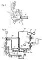
- FIG. 1 is a sketch of a generic plant for the production of cement shown. Although the structure of different systems differs, the sequence of the essential elements between different systems is comparable.
- the plant after FIG. 1 flows to be treated thermally raw meal from the upper end of the heat exchanger 1 via the individual cyclones in the second cyclone 1 a. Not shown here flows at this point already preheated raw meal in the ascending branch 2 of the calciner and is entrained there with the process gas and deacidified in the heat of the rotary kiln exhaust gases and an additional firing in this part of the calciner.
- Some systems have a vortex chamber 3, in which the process gases can burn out to oxidise harmful exhaust gases oxidatively.
- the calcined raw meal flows into the lowest cyclone 1 b, where it is separated and passed into the rotary kiln inlet chamber 5.
- the process gas separates here from the calcined raw meal and rises in the heat exchanger 1 for preheating the raw meal, where it flows counter to the raw meal.
- the raw meal introduced into the rotary kiln inlet chamber 5 then flows into the rotary kiln 6, where it is sintered to clinker. After sintering, the clinker falls from the rotary kiln 6 in the clinker cooler 8, where the freshly sintered clinker is rapidly quenched by means of cooling air.
- the heated by the clinker in the clinker cooler 8 cooling air takes two ways. The first path leads as secondary air into the rotary kiln 6, whereas a second path leads via the tertiary air duct 7 into the ascending branch 2 of the calciner.
- hot process gas is taken from the gas outlet of the calciner in order to generate electrical energy therefrom.
- the gas outlet is arranged at the lower end of the descending branch 4 of the calciner, where shortly thereafter the calcined raw meal separates from the process gas.
- FIG. 1 provided with reference numeral 10.
- An alternative or cumulative for the removal of hot process gas is the gas-side outlet of the first cyclone 1b in the heat exchanger in the gas flow direction, which is provided with the reference numeral 11.
- As a return for the removed and cooled in the steam process gas of the gas inlet of the second cyclone seen in the gas flow direction is 1 a or third cyclone.
- the process gas taken at the excellent points and returned to the process disturbs the process of producing cement only slightly or not at all. How to proceed with the process gas is sketched in more detail in the next figure.
- FIG. 2 is a section of FIG. 1 illustrated with a marked steam boiler 21, which is provided for removing heat from the hot process gas.
- a marked steam boiler 21 which is provided for removing heat from the hot process gas.
- Process gas taken and each is supplied via a process gas line 20 to a steam boiler 21.
- the heat of the process gas is used for heating steam and the cooled process gas flows via a process gas line 22 to a control device 23 and from there via a process gas line 24 to the location of the return, in FIG. 1 is provided with reference numeral 12.
- the steam to be heated in the steam line 26 enters the steam boiler 21 and leaves it again via the steam line 26.
- the extracted process gas is dust laden
- the dust at least partially separated in the boiler 21 from the process gas and on the Dust removal device 25 is removed from the boiler 21.
- the dust thus obtained can optionally be placed in the rotary kiln inlet chamber 5 and / or in a cement mill.
- FIG. 3 Finally, an overall outline of an embodiment of a plant for the production of cement together with a flow chart is shown, which represents the entire process gas extraction and its use.
- the plant for the production of cement shown on the left below corresponds to the annex in accordance with FIGS. 1 and 2 , Essential here is the flow chart for the use of waste heat.
- low-calorific waste heat with a low temperature is obtained at the upper outlet of the heat exchanger 1 in a separate heat exchanger 30 and also in a further heat exchanger 40 at the end of the clinker cooler 8.
- Both the waste heat from heat exchanger 1 and the waste heat from clinker cooler 8 are combined via the steam lines 30a and 40a and the waste heat thus obtained is given as preheated flow 21v in the boiler 21, where the extracted process gas overheats the steam.
- the superheated steam is passed from the steam boiler via the steam line 21 n into a turbine 50, which is connected to a generator for generating electrical energy.
- the condenser 52 the steam is cooled, passes through a deaerator 53, which is coupled to a chemical treatment stage 53 a and is compressed by a pump 54.
- the cooled steam divides into two branches, wherein a first branch is guided as a flow 30v to the heat exchanger 30 to use the waste heat of the heat exchanger 1 and a second branch as a flow 40v to use the waste heat of the clinker cooler 8.
- the inventive circuit the steam for generating electrical energy is first preheated by the waste heat at low temperature and further heated by the withdrawn process gas, so that the steam is overheated and correspondingly carries a large amount of energy in the turbine by relaxing and condensing in can be used in a known manner.
Landscapes
- Engineering & Computer Science (AREA)
- Chemical & Material Sciences (AREA)
- Ceramic Engineering (AREA)
- Physics & Mathematics (AREA)
- Thermal Sciences (AREA)
- Materials Engineering (AREA)
- Structural Engineering (AREA)
- Organic Chemistry (AREA)
- Mechanical Engineering (AREA)
- General Engineering & Computer Science (AREA)
- Environmental & Geological Engineering (AREA)
- Combustion & Propulsion (AREA)
- Life Sciences & Earth Sciences (AREA)
- Sustainable Development (AREA)
- Sustainable Energy (AREA)
- Waste-Gas Treatment And Other Accessory Devices For Furnaces (AREA)
- Curing Cements, Concrete, And Artificial Stone (AREA)
- Furnace Details (AREA)
- Muffle Furnaces And Rotary Kilns (AREA)
Description
- Die Erfindung betrifft ein Verfahren zur Nutzung der Abwärme einer Anlage zur Herstellung von Zement, wobei Wärme eines Prozessgases über einen ersten Wärmetauscher zur Erhitzung von Wasserdampf genutzt wird, und wobei die Anlage zur Herstellung von Zement mindestens einen Calcinator und mindestens einen zweiten Wärmetauscher, der aus einer Abfolge von Zyklonen besteht, zum Erhitzen von Rohmehl aufweist und eine Anlage zur Herstellung von Zement, wobei die Anlage zur Herstellung von Zement mindestens einen Calcinator und mindestens einen zweiten Wärmetauscher, der aus einer Abfolge von Zyklonen besteht, zum Erhitzen von Rohmehl aufweist.
- Anlagen zur Herstellung von Zement weisen in der Regel einen sehr hohen Wärmeumsatz auf. Um die Abwärme einer Anlage von Zement effizient zu nutzen, wird die im Prozess entstehende Abwärme über Wärmetauscher, die in der Anlage verteilt sind, wieder in den Prozess zurück geführt. Bei der Rückführung der Wärme, der Rekuperation, ist es notwendig, dass die Wärme bei möglichst hoher Temperatur in den Prozess zurück geführt wird, um den notwendigen Energieeintrag zur Erzeugung der Prozesswärme zu verringern. Zur Rekuperation eignet sich aber nicht jede in der Anlage entstehende Abwärme. In der Regel werden nur solche Wärmequellen rekuperiert, die eine deutlich höhere Temperatur als 300°C aufweisen. Neben der Wärmerückführung in den Prozess ist es auch bekannt, die nicht rekuperierte, niederkalorische Wärme zur Trocknung von Rohmaterial zu nutzen oder zur Aufbereitung von Brennstoffen einzusetzen.
- Neben der Aufbereitung von Rohmaterial und Brennstoffen ist man auch dazu übergegangen, die nicht rekuperierte Abwärme in elektrische Energie umzuwandeln. In Anlagen zur Herstellung von Zement sind dazu im Wesentlichen zwei Dampfkesselsysteme bekannt. Ein erstes System wird SP-Boiler genannt von englisch "Suspension Preheater", und dieser Boiler ist dem Zyklonwärmetauscher nachgeschaltet, der in Anlagen zur Herstellung von Zement zur Vorwärmung des Rohmehls genutzt wird. Ein zweites System wird AQC-Boiler genannt von englisch "Air Quenched Clinkercooler", der im Abluftweg des Klinkerkühlers einer Anlage zur Herstellung von Zement nachgeschaltet ist.
- In der deutschen Offenlegungsschrift
DE 195 18 926 A1 wird ein Verfahren zur Nutzung der Abwärme einer Anlage zur Herstellung von Zement offenbart. Nach der dort stehenden Lehre soll Wärme zwischen dem zweiten und dritten Zyklon der Anlage zur Herstellung von Zement entnommen und nach Nutzung als Restwärme wieder zurückgeführt werden. Der Druckverlust zwischen zwei unmittelbar aufeinander folgende Zyklone wird dabei sehr stark und damit lässt die Trennleistung der aufeinander folgenden Zyklone stark nach. - In der US-Patentanmeldung
US 2009/293303 A1 wird ein verfahren offenbart, in welchem Wärme unspezifisch dem Vorwärmer entnommen werden soll. Eine nach Nutzung der Wärme vorhandene Restwärme wird nicht in den Prozess zurückgeführt. Bei dieser Verfahrensführung verarmt die Menge des Prozessgases, das am Eingang der Anlage zusätzlich bereits gestellt werden muss. - Schließlich wird in der deutschen Offenlegungsschrift
DE 25 23 794 A1 ein verfahren offenbart, bei dem Wärme zwischen dem zweiten und dritten Zyklonwärmetauscher entnommen wird. Auch bei dieser Prozessführung wird keine Restwärme zurück in den Prozess geführt. - Diese bekannten Systeme zur Wandlung der Abwärme in elektrische Energie weisen aber in der Regel aufgrund der niedrigen Temperatur der nicht rekuperierten Abwärme eine unerwünscht geringe Wandlungseffizienz auf. Denn je höher die Temperatur der Abwärme ist, desto höher ist das Vermögen einer allgemeinen Wärmekraftmaschine, Wärme in mechanische Arbeit umzusetzen, die wiederum durch einen Generator in elektrische Energie umgewandelt wird.
- Um den Wirkungsgrad bei der Wandlung von nicht rekuperierter Abwärme in elektrische Energie in einer Anlage zur Herstellung von Zement zu verbessern, wäre es mithin notwendig, eine Abwärmequelle zu schaffen, die eine wesentlich höhere Temperatur zur Verfügung stellt als es in bekannten Anlagen zur Herstellung von Zement bekannt ist.
- Aufgabe der Erfindung ist es deshalb, ein Verfahren und eine dazu korrespondierende Anlage zur Herstellung von Zement zur Verfügung zu stellen, in dem eine den herstellungsprozess nicht schadende Abwärmequelle von hoher Temperatur zur Verfügung steht.
- Die Aufgabe der Erfindung wird gelöst durch das Verfahren nach Anspruch 1 und Ausgestaltungen nach den darauf rückbezogenen Ansprüchen und durch eine Anlage zur Herstellung von Zement nach Anspruch 6 und Ausgestaltungen nach den darauf rückbezogenen Ansprüchen.
- Erfindungsgemäß wird vorgeschlagen, der Anlage zur Herstellung von Zement Prozessgas am Gasaustritt des Calcinators, der am unteren Ende des absteigenden Ast des Calcinators angeordnet ist und/oder am gasseitigen Austritt des im Wärmetauscher in Gasströmungsrichtung ersten Zyklons zu entnehmen. Diesem Prozessgas wird Wärme in einem Dampfkessel entnommen, und das im Dampfkessel abgekühlte Prozessgas wird sodann in den im Wärmetauscher in Gasströmungsrichtung zweiten oder dritten Zyklon zurückgeführt.
- In einer Anlage zur Herstellung von Zement existieren verschiedene Orte, an denen heiße Prozessgase zur Verfügung stehen. Dabei können jedoch nicht sämtliche Stellen als Entnahmestellen für Prozessgas dienen, weil der Eingriff in das Verfahren zur Herstellung von Zement damit gestört würde. Überraschender Weise hat sich in längeren Versuchsreihen gezeigt, dass eine Entnahme von heißem Prozessgas am Gasaustritt des Calcinators, der am unteren Ende des absteigenden Ast des Calcinators angeordnet ist und/oder am gasseitigen Austritt des im Wärmetauscher in Gasströmungsrichtung ersten Zyklons das Verfahren zur Herstellung von Zement nur wenig beeinflusst. Es ist bei der Entnahme einer nicht vernachlässigbaren Menge Prozesswärme zu erwarten, dass je nach Entnahmeort die Vorwärmung des Rohmehls nur unzureichend ist und damit die Calcinierungsreaktion im Calcinator nicht vollständig stattfindet. Sofern im Calcinator Wärme entnommen wird, so könnte die Calcinierungsreaktion unvollständig sein wodurch der Klinker als Zwischenprodukt einen zu hohen Anteil an freiem Kalk aufweist. Auch könnten im Rohmehl vorhandene Salze ab einem bestimmten Taupunkt verkleben und die Anlage zur Herstellung von Zement zusetzen. Schließlich könnte die in vielen Anlagen zur Herstellung von Zement durchgeführte gestufte Verbrennung unzureichend sein und damit könnte die Anlage einen zu hohen NOx-Ausstoß zeigen. Auch könnte eine kontrollierte Verbrennungsführung mit wechselnd reduktiven und oxidativen Bedingungen zur Vermeidung der CO und NOx-Emission durch die Entnahme von Prozesswärme gestört werden.
- Um das dem Prozess entnommene Prozessgas wieder in den Prozess zurück zu führen, hat es sich als vorteilhaft erwiesen, wenn das abgekühlte Prozessgas in den im Wärmetauscher in Gasströmungsrichtung zweiten oder dritten Zyklon zurückgeführt wird. Erfindungsgemäß findet also in Gasströmungsrichtung gesehen am Anfang des Wärmetauschers und am Gasaustritt des Calcinators, der am unteren Ende des absteigenden Ast des Calcinators angeordnet ist, ein Prozessgaskreislauf neben dem Prozessgasfluss in der Anlage statt.
- Das Prozessgas aus dem Gasaustritt des Calcinators und/oder aus dem gasseitigen Austritt des im Wärmetauscher in Gasströmungsrichtung ersten Zyklons weist hohe Mengen Staub auf. Daher ist es notwendig, den Staub aus dem Prozessgas zumindest teilweise zu entfernen. Dieser entfernte Staub ist jedoch Rohmaterial oder teilweise bis vollständig calciniertes Zwischenprodukt und kann wieder in den Prozess zurückgeführt werden. Um das im Prozess verbliebene, nicht entnommene Prozessgas nicht unerwünscht zu kühlen, wird in Ausgestaltung der Erfindung vorgeschlagen, den abgeschiedenen und auch erkalteten Staub in eine Zementmühle zu geben, wo es mit dem fertig gebrannten Klinker gemeinsam vermahlen wird. Es ist aber auch möglich, den rückzuführenden Staub in die Drehofeneinlaufkammer des Drehrohrofens aufzugeben, um den Staub als Zwischenpodukt im Drehofen zu sintern. Um die dem Prozess entnommene Prozessgasmenge zu regeln, wird erfindungsgemäß vorgeschlagen, die Gasmenge über ein Regelventil oder einen Schieber oder eine Klappe in der Gasrückführung, wo das Prozessgas zumindest teilweise entstaubt ist, zu regeln. An dieser Stelle ist das Prozessgas auch abgekühlt, wodurch eine problematische Gasmengenregelung mit heißem Gas umgangen werden kann.
- Die alternative Entnahme von Prozessgas zur Nutzung der Abwärme statt der Nutzung der niederkalorischen Abwärme am Ende des Wärmetauschers oder am Ende des Klinkerkühlers lässt die niederkalorische Abwärme bestehen. In besonderer Ausgestaltung der Erfindung ist vorgesehen, zur Erzeugung von elektrischer Energie aus dem aus niederkalorischer Abwärme erzeugten Dampfs, diesen eigentlich zu kalten Dampf mit Hilfe der heißen Prozessgase aufzuheizen, um die Temperatur des mit der Abwärme aus Wärmetauscher und Klinkerkühler erzeugten Dampfs zu erhöhen. Es wird Wärme aus dem Prozessgas mit Abwärme, die gasströmungsseitig nach dem Wärmetauscher oder materialflussseitig nach dem Klinkerkühler entnommen wird, vereinigt, indem kälterer Dampf als Wärmeträger durch das erfindungsgemäß aufgeheizte Prozessgas weiter aufgeheizt wird. Dadurch wird die Abwärme der Anlage zur Herstellung von Zement in größtmöglichem Umfang genutzt.
- Die Erfindung wird anhand der folgenden Figuren näher erläutert.
- Es zeigt:
- Figur 1
- eine Skizze einer gattungsgemäßen Anlage zur Herstellung von Zement mit eingezeichneten Entnahmeorten für heißes Prozessgas gemäß der Erfindung,
- Figur 2
- eine erfindungsgemäße Anlage zur Herstellung von Zement in einer ersten Ausgestaltung,
- Figur 3
- eine erfindungsgemäße Anlage zur Herstellung von Zement in einer zweiten Ausgestaltung,
- In
Figur 1 ist eine Skizze einer gattungsgemäßen Anlage zur Herstellung von Zement dargestellt. Wenngleich sich der Aufbau unterschiedlicher Anlagen unterscheidet, so ist die Abfolge der Wesentlichen Elemente zwischen verschiedenen Anlagen miteinander vergleichbar. In der Anlage nachFigur 1 fließt das thermisch zu behandelnde Rohmehl vom oberen Ende des Wärmetauschers 1 über die einzelnen Zyklone in bis zum zweiten Zyklon 1 a. Hier nicht eingezeichnet, fließt das an dieser Stelle bereits vorgewärmte Rohmehl in den aufsteigenden Ast 2 des Calcinators und wird dort mit dem Prozessgas mitgerissen und in der Wärme der Drehofenabgase und einer zusätzlichen Feuerung in diesem Teil des Calcinators entsäuert. Manche Anlagen weisen eine Wirbelkammer 3 auf, in der die Prozessgase ausbrennen können, um schädliche Abgase oxidativ zu verbrennen. Nach Passage der Wirbelkammer 3 fließt das calcinierte Rohmehl in den untersten Zyklon 1 b, wo es abgetrennt und in die Drehofeneinlaufkammer 5 geleitet wird. Das Prozessgas trennt sich hier vom calcinierten Rohmehl und steigt im Wärmetauscher 1 zum Vorwärmen des Rohmehls auf, wo es dem Rohmehl entgegen fließt. Das in die Drehofeneinlaufkammer 5 eingeleitete Rohmehl fließt sodann in den Drehofen 6, wo es zu Klinker gesintert wird. Nach der Sinterung fällt der Klinker aus dem Drehofen 6 in den Klinkerkühler 8, wo der frisch gesinterte Klinker mit Hilfe von Kühlluft rasch abgeschreckt wird. Die durch den Klinker im Klinkerkühler 8 aufgewärmte Kühlluft nimmt zwei Wege. Der erste Weg führt als Sekundärluft in den Drehofen 6, hingegen führt ein zweiter Weg über die Tertiärluftleitung 7 in den aufsteigenden Ast 2 des Calcinators. - Gemäß der Erfindung ist nun vorgesehen, dass heißes Prozessgas am Gasaustritt des Calcinators entnommen wird, um daraus elektrische Energie zu erzeugen. In der vorliegenden Anlage ist der Gasaustritt am unteren Ende des absteigenden Ast 4 des Calcinators angeordnet, wo sich kurz darauf das calcinierte Rohmehl vom Prozessgas trennt. Diese Stelle ist in
Figur 1 mit Bezugszeichen 10 versehen. Eine Alternative oder Kumulative zur Entnahme von heißem Prozessgas ist der gasseitige Austritt des im Wärmetauscher in Gasströmungsrichtung ersten Zyklones 1 b, das mit dem Bezugszeichen 11 versehen ist. Als Rückführort für das entnommene und im Dampfkessel abgekühlte Prozessgas ist der Gaseintritt des in Gasströmungsrichtung gesehen zweiten Zyklones 1 a oder dritten Zyklones. Das an den ausgezeichneten Stellen entnommene und wieder zurück geführte Prozessgas stört das Verfahren zur Herstellung von Zement nur wenig bis gar nicht. Wie mit dem Prozessgas weiter verfahren wird, ist in der nächsten Figur näher skizziert. - In
Figur 2 ist ein Ausschnitt ausFigur 1 mit einem eingezeichneten Dampfkessel 21 dargestellt, der zur Entnahme von Wärme aus dem heißen Prozessgas vorgesehen ist. Erfindungsgemäß ist vorgesehen, dass an Stelle 10 und/oder 11 gemäßFigur 1 Prozessgas entnommen und je über eine Prozessgasleitung 20 einem Dampfkessel 21 zugeführt wird. Dort wird die Wärme des Prozessgases zur Aufheizung von Dampf verwendet und das abgekühlte Prozessgas fließt über eine Prozessgasleitung 22 zu einer Regelvorrichtung 23 und von dort über eine Prozessgasleitung 24 zum Ort der Rückführung, die inFigur 1 mit Bezugszeichen 12 versehen ist. Der zu erhitzende Dampf in Dampfleitung 26 tritt in den Dampfkessel 21 ein und verlässt ihn wieder über die Dampfleitung 26. Da das entnommene Prozessgas staubbeladen ist, ist in Ausgestaltung der Erfindung vorgesehen, dass der Staub zumindest teilweise im Dampfkessel 21 vom Prozessgas abgetrennt und über die Entstaubungsvorrichtung 25 aus dem Dampfkessel 21 entfernt wird. Der so erhaltene Staub kann wahlweise in die Drehofeneinlaufkammer 5 und/oder in eine Zementmühle gegeben werden. - In
Figur 3 ist schließlich eine Gesamtskizze einer Ausgestaltung einer Anlage zur Herstellung von Zement gemeinsam mit einem Flussdiagramm dargestellt, welches die gesamte Prozessgasentnahme und seine Nutzung darstellt. Die links unten eingezeichnete Anlage zur Herstellung von Zement entspricht der Anlage gemäß denFiguren 1 und2 . Wesentlich ist hier das Flussdiagramm zur Nutzung der Abwärme. In dieser Schaltung wird niederkalorische Abwärme mit geringer Temperatur am oberen Ausgang des Wärmetauschers 1 in einem eigenen Wärmetauscher 30 und auch in einem weiteren Wärmetauscher 40 am Ende des Klinkerkühlers 8 gewonnen. Sowohl die Abwärme aus Wärmetauscher 1 wie auch die Abwärme aus Klinkerkühler 8 werden über die Dampfleitungen 30a und 40a vereint und die so gewonnene Abwärme wird als vorgewärmter Vorlauf 21v in den Dampfkessel 21 gegeben, wo das entnommene Prozessgas den Dampf in überhitzt. Der überhitzte Dampf wird aus dem Dampfkessel über die Dampfleitung 21 n in eine Turbine 50 geleitet, die mit einem Generator zur Erzeugung von elektrischer Energie verbunden ist. Im Kondensator 52 wird der Dampf abgekühlt, durchläuft einen Entlüfter 53, der mit einer chemischen Behandlungsstufe 53a gekoppelt ist und wird durch eine Pumpe 54 verdichtet. Nach Austritt aus Pumpe 54 teilt sich der abgekühlte Dampf auf in zwei Äste, wobei ein erster Ast als Vorlauf 30v zum Wärmetauscher 30 zur Nutzung der Abwärme des Wärmetauschers 1 und ein zweiter Ast als Vorlauf 40v zur Nutzung der Abwärme des Klinkerkühlers 8 geführt ist. Durch die erfindungsgemäße Schaltung wird der Dampf zur Erzeugung von elektrischer Energie zunächst durch die Abwärme mit niedriger Temperatur vorgewärmt und durch das entnommene Prozessgas weiter aufgeheizt, so dass der Dampf überhitzt ist und entsprechend eine hohe Energiemenge trägt, die in der Turbine durch Entspannen und Kondensieren in an sich bekannter Weise genutzt werden kann.BEZUGSZEICHENLISTE 1 Wärmetauscher 23 Regelvorrichtung 1a Zyklon 24 Prozessgasleitung, Rückführung 1b Zyklon 25 Entstaubungsvorrichtung 2 Calcinator (aufsteigender Ast) 26 Dampfleitung 3 Wirbelkammer 4 Calcinator (absteigender Ast) 30 Wärmetauscher 5 Drehofeneinlaufkammer 30a Dampfleitung 6 Drehofen 30v Vorlauf 7 Tertiärluftleitung 8 Klinkerkühler 40 Wärmetauscher 9 Klinkeraustritt 40a Dampfleitung 10 Entnahmestelle, 1. Alternative 40v Vorlauf 11 Entnahmestelle, 2. Alternative 12 Rückführstelle, 1. Alternative 50 Turbine 13 Rückführstelle, 2. Alternative 51 Generator 52 Kondensator 20 Prozessgasleitung, Entnahme 53 Entlüfter 21 Dampfkessel 53a chemische Behandlungsstufe 21n Dampfleitung, Nachlauf 54 Pumpe 21v Dampfleitung, Vorlauf 22 Dampfleitung
Claims (10)
- Verfahren zur Nutzung der Abwärme einer Anlage zur Herstellung von Zement w
obei Wärme eines Prozessgases über einen ersten Wärmetauscher (21) zur
Erhitzung von Wasserdampf genutzt wird, und
wobei die Anlage zur Herstellung von Zement mindestens einen Calcinator (2, 4 ) und mindestens einen zweiten Wärmetauscher (1), der aus einer Abfolge von Zyklonen (1 a, 1 b) besteht, zum Erhitzen von Rohmehl aufweist,
dadurch gekennzeichnet, dass
das Prozessgas- am Gasaustritt (10) des Calcinators (4), der am unteren Ende des absteigenden Ast (4) des Calcinators angeordnet ist, und/oder- am gasseitigen Austritt (11) des im zweiten Wärmetauscher (1) in Gasströmungsrichtung ersten Zyklones (1 b)entnommen wird und nach Entzug der Wärme in einem Dampfkessel (21) das abgekühlte Prozessgas in den im zweiten Wärmetauscher (1) in Gasströmungsrichtung zweiten Zyklon (1a) oder dritten Zyklon zurückgeführt wird. - Verfahren nach Anspruch 1
gekennzeichnet durch
die Rückführung des im Kesselsystem aus dem Prozessgas abgeschiedenen Staubes in die Drehofeneinlaufkammer (5) eines in der Anlage vorhandenen Drehrohrofens (6) und/oder Zementmühle - Verfahren nach Anspruch 1,
gekennzeichnet durch
Vereinigung der Wärme aus dem Prozessgas mit Abwärme, die gasströmungsseitig nach dem Wärmetauscher (1) oder materialflussseitig nach dem Klinkerkühler (8) entnommen wird. - Verfahren nach einem der Ansprüche 1 bis 3,
gekennzeichnet durch
eine Regelung der Menge des entnommenen Prozessgases, wobei das Stellglied ein Gasregler (23) im abgekühlten Gasstrom in einer Rückführleitung ist. - Verfahren nach einem der Ansprüche 1 bis 4,
gekennzeichnet durch
die Entstaubung des Prozessgases im Dampfkessel (21). - Anlage zur Herstellung von Zement
wobei die Anlage zur Herstellung von Zement mindestens einen Calcinator (2, 4) und mindestens einen Wärmetauscher (1), der aus einer Abfolge von Zyklonen (1 a, 1 b) besteht, zum Erhitzen von Rohmehl aufweist,
dadurch gekennzeichnet, dass
eine Prozessgasabnahmestelle (10, 11)- am Gasaustritt (10) des Calcinators (2), der am unteren Ende des absteigenden Ast (4) des Calcinators angeordnet ist, und/oder- am gasseitigen Austritt (11) des im Wärmetauscher (1) in Gasströmungsrichtung ersten Zyklones (1a)vorhanden ist, und
die Prozessgasabnahmestelle (10, 11) zu einem Dampfkessel (21) führt, wo Wärme des Prozessgases über einen Wärmetauscher zur Erhitzung von Wasserdampf genutzt wird, und wobei
eine Rückführleitung (24) für das Prozessgas in den im Wärmetauscher (1) in
Gasströmungsrichtung zweiten Zyklon (1 b) oder dritten Zyklon vorhanden ist. - Anlage nach Anspruch 6,
dadurch gekennzeichnet, dass
eine Rückführung des im Kesselsystem aus dem Prozessgas abgeschiedenen Staubes in die Drehofeneinlaufkammer (5) eines in der Anlage vorhandenen Drehrohrofens (6) und/oder Zementmühle vorhanden ist. - Anlage nach Anspruch 7,
gekennzeichnet durch
einen Vorlauf (21 v) im Dampfkessel (21), der von Abwärme, die gasströmungsseitig nach dem Wärmetauscher (1) und/oder materialflusseitig nach dem Klinkerkühler (8) entnommen ist, vorgewärmt ist. - Anlage nach einem der Ansprüche 6 bis 7
dadurch gekennzeichnet, dass
eine Regelvorrichtung zur Regelung der Menge des entnommenen Prozessgases vorhanden ist, wobei das Stellglied ein Gasregler (23) im abgekühlten Gasstrom in einer Rückführleitung (22, 24) ist. - Anlage nach einem der Ansprüche 6 bis 9,
dadurch gekennzeichnet, dass
eine Vorrichtung zur Entstaubung (25) des Prozessgases im Dampfkessel (21) vorhanden ist.
Applications Claiming Priority (2)
| Application Number | Priority Date | Filing Date | Title |
|---|---|---|---|
| DE102012020300.4A DE102012020300B4 (de) | 2012-10-17 | 2012-10-17 | Verfahren zur Nutzung der Abwärme einer Anlage zur Herstellung von Zement und Anlage zur Herstellung von Zement |
| PCT/EP2013/071123 WO2014060275A1 (de) | 2012-10-17 | 2013-10-10 | Verfahren zur nutzung der abwärme einer anlage zur herstellung von zement anlage zur zementherstellung |
Publications (2)
| Publication Number | Publication Date |
|---|---|
| EP2909553A1 EP2909553A1 (de) | 2015-08-26 |
| EP2909553B1 true EP2909553B1 (de) | 2016-11-30 |
Family
ID=49447529
Family Applications (1)
| Application Number | Title | Priority Date | Filing Date |
|---|---|---|---|
| EP13779541.5A Revoked EP2909553B1 (de) | 2012-10-17 | 2013-10-10 | Verfahren zur nutzung der abwärme einer anlage zur herstellung von zement anlage zur zementherstellung |
Country Status (8)
| Country | Link |
|---|---|
| US (1) | US9725362B2 (de) |
| EP (1) | EP2909553B1 (de) |
| CN (1) | CN104769378B (de) |
| BR (1) | BR112015008630A2 (de) |
| DE (1) | DE102012020300B4 (de) |
| DK (1) | DK2909553T3 (de) |
| RU (1) | RU2015112159A (de) |
| WO (1) | WO2014060275A1 (de) |
Cited By (1)
| Publication number | Priority date | Publication date | Assignee | Title |
|---|---|---|---|---|
| WO2025073567A1 (de) * | 2023-10-04 | 2025-04-10 | Khd Humboldt Wedag Gmbh | Anlage zur herstellung von zement mit auskopplung von wärmeenergie |
Families Citing this family (11)
| Publication number | Priority date | Publication date | Assignee | Title |
|---|---|---|---|---|
| DE102014010044B3 (de) * | 2014-06-27 | 2015-12-24 | Khd Humboldt Wedag Gmbh | Verfahren zur Abwärmenutzung in einer Anlage zur Zementherstellung und Anlage zur Zementherstellung |
| DE102016003751B4 (de) * | 2016-03-26 | 2019-09-26 | Khd Humboldt Wedag Gmbh | Anlage zur Herstellung von Zementklinker mit vereinzeltem Mitstrom-Durchflusscalinator |
| GB201904480D0 (en) * | 2019-03-29 | 2019-05-15 | Origen Power Ltd | Calcination process |
| CN111750682A (zh) * | 2019-03-29 | 2020-10-09 | 川崎重工业株式会社 | 余热回收系统以及其运转方法 |
| WO2021185498A1 (de) * | 2020-03-17 | 2021-09-23 | Mitsubishi Power Europe Gmbh | Anlage zur nutzung von in einem abgas- oder abluftstrom einer industriellen produktionsanlage enthaltener wärmeenergie |
| DE102020118546B4 (de) | 2020-07-14 | 2023-02-16 | Khd Humboldt Wedag Gmbh | Verfahren zum Betrieb einer Anlage zur Herstellung von Zementklinker |
| CN112706284B (zh) * | 2020-12-07 | 2022-02-25 | 曲靖市沾益区祥达建材有限公司 | 一种基于烧结窑余热的制砖原料高效陈化工艺 |
| WO2022179847A1 (de) | 2021-02-24 | 2022-09-01 | Thyssenkrupp Industrial Solutions Ag | Höhenoptimierte vorrichtung zur wärmebehandlung von mineralischen stoffen |
| BE1029138B1 (de) * | 2021-02-24 | 2022-09-19 | Thyssenkrupp Ind Solutions Ag | Höhenoptimierte Vorrichtung zur Wärmebehandlung von mineralischen Stoffen |
| DE102021205828A1 (de) | 2021-06-09 | 2022-12-15 | Refratechnik Holding Gmbh | Verfahren und Vorrichtung zur Herstellung eines calcinierten Materials |
| DE102021134014A1 (de) * | 2021-12-21 | 2023-06-22 | Dürr Systems Ag | Prozessanlage für das Umsetzen eines feststoffförmigen Eingangsmaterials in ein feststoffförmiges Prozessprodukt |
Citations (4)
| Publication number | Priority date | Publication date | Assignee | Title |
|---|---|---|---|---|
| DE2523794A1 (de) | 1974-05-31 | 1975-12-11 | Fives Cail Babcock | Anlage zur herstellung von zement im trockenverfahren |
| DE2610436A1 (de) | 1975-03-12 | 1976-09-16 | Ass Portland Cement | Integriertes reaktionsverfahren |
| DE19518926A1 (de) | 1995-05-23 | 1996-11-28 | Krupp Polysius Ag | Verfahren und Vorrichtung zur Herstellung von gebranntem Gut |
| EP2294028B1 (de) | 2008-06-05 | 2012-05-30 | Cemex Research Group AG | Verbesserte gleichzeitige elektrizitätserzeugung bei der herstellung von zementklinkern |
Family Cites Families (8)
| Publication number | Priority date | Publication date | Assignee | Title |
|---|---|---|---|---|
| IT1121731B (it) * | 1975-10-28 | 1986-04-23 | Fives Cail Babcock | Perfezionamenti nelle installazioni di fabbricazione di cemento per via secca |
| JPS56113988A (en) * | 1980-02-15 | 1981-09-08 | Sumitomo Cement Co | Method and device for recovering exhaust gas from combustion furnace in generating set using combustible as fuel |
| DE3341695A1 (de) * | 1983-11-18 | 1985-05-30 | Klöckner-Humboldt-Deutz AG, 5000 Köln | Verfahren und anlage zum brennen von feinkoernigem gut, insbesondere zur herstellung von zementklinker aus zementrohmehl |
| CN100362302C (zh) * | 2004-06-21 | 2008-01-16 | 孙义燊 | 水泥预分解窑废气余热的发电系统及其发电方法 |
| EP2153154A1 (de) * | 2007-06-12 | 2010-02-17 | FLSmidth A/S | Verfahren und anlage zur gleichzeitigen erzeugung von elektrizität und zementklinkern |
| US20090293303A1 (en) | 2008-06-03 | 2009-12-03 | Synagro Technologies, Inc. | Biosolid Drying and Utilization in Cement Processes |
| DE102011050677B4 (de) * | 2011-05-27 | 2014-08-28 | Südbayerisches Portland-Zementwerk Gebr. Wiesböck & Co. GmbH | Vorrichtung und Verfahren zur Herstellung von Zementklinker |
| DE102011052561B4 (de) * | 2011-05-27 | 2015-03-05 | Südbayerisches Portland-Zementwerk Gebr. Wiesböck & Co. GmbH | Verfahren und Vorrichtung zum Brennen von Klinker |
-
2012
- 2012-10-17 DE DE102012020300.4A patent/DE102012020300B4/de not_active Expired - Fee Related
-
2013
- 2013-10-10 RU RU2015112159A patent/RU2015112159A/ru not_active Application Discontinuation
- 2013-10-10 BR BR112015008630A patent/BR112015008630A2/pt not_active IP Right Cessation
- 2013-10-10 DK DK13779541.5T patent/DK2909553T3/en active
- 2013-10-10 EP EP13779541.5A patent/EP2909553B1/de not_active Revoked
- 2013-10-10 WO PCT/EP2013/071123 patent/WO2014060275A1/de not_active Ceased
- 2013-10-10 CN CN201380058174.7A patent/CN104769378B/zh active Active
- 2013-10-10 US US14/435,622 patent/US9725362B2/en not_active Expired - Fee Related
Patent Citations (4)
| Publication number | Priority date | Publication date | Assignee | Title |
|---|---|---|---|---|
| DE2523794A1 (de) | 1974-05-31 | 1975-12-11 | Fives Cail Babcock | Anlage zur herstellung von zement im trockenverfahren |
| DE2610436A1 (de) | 1975-03-12 | 1976-09-16 | Ass Portland Cement | Integriertes reaktionsverfahren |
| DE19518926A1 (de) | 1995-05-23 | 1996-11-28 | Krupp Polysius Ag | Verfahren und Vorrichtung zur Herstellung von gebranntem Gut |
| EP2294028B1 (de) | 2008-06-05 | 2012-05-30 | Cemex Research Group AG | Verbesserte gleichzeitige elektrizitätserzeugung bei der herstellung von zementklinkern |
Non-Patent Citations (3)
| Title |
|---|
| HELMUT LEBINGER ET AL: "Fit for the future", ZKG, February 2012 (2012-02-01), pages 35 - 48, XP055408358 |
| T. INO ET AL: "Waste Heat recovery power generation (WHRPG) for cement plants", CEMENT INTERNATIONAL, vol. 8, January 2010 (2010-01-01), pages 36 - 40, 42, 44-45, XP055408351 |
| TATSUO INO: "Waste Heat Recovery Power Generation (WHRPG) for Cement Plants", 6TH INTERNATIONAL VDZ CONGRESS, 2009, pages 166 - 173, XP055408367, ISBN: 978-3-7640-0513-9 |
Cited By (1)
| Publication number | Priority date | Publication date | Assignee | Title |
|---|---|---|---|---|
| WO2025073567A1 (de) * | 2023-10-04 | 2025-04-10 | Khd Humboldt Wedag Gmbh | Anlage zur herstellung von zement mit auskopplung von wärmeenergie |
Also Published As
| Publication number | Publication date |
|---|---|
| EP2909553A1 (de) | 2015-08-26 |
| DE102012020300A1 (de) | 2014-04-17 |
| WO2014060275A1 (de) | 2014-04-24 |
| US9725362B2 (en) | 2017-08-08 |
| RU2015112159A (ru) | 2016-12-10 |
| BR112015008630A2 (pt) | 2017-08-08 |
| DE102012020300B4 (de) | 2016-05-12 |
| CN104769378B (zh) | 2017-05-03 |
| US20150274591A1 (en) | 2015-10-01 |
| CN104769378A (zh) | 2015-07-08 |
| DK2909553T3 (en) | 2017-03-06 |
Similar Documents
| Publication | Publication Date | Title |
|---|---|---|
| DE102012020300B4 (de) | Verfahren zur Nutzung der Abwärme einer Anlage zur Herstellung von Zement und Anlage zur Herstellung von Zement | |
| EP3161400B1 (de) | Verfahren zur abwärmenutzung in einer anlage zur zementherstellung und anlage zur zementherstellung | |
| EP3788314B1 (de) | Oxyfuel-klinkerherstellung mit spezieller sauerstoffzugasung | |
| EP2545337B1 (de) | Verfahren und vorrichtung zur herstellung von zementklinker | |
| EP3672919B1 (de) | Anlage und verfahren zur herstellung von zementklinker | |
| EP0143395A1 (de) | Verfahren und Anlage zum Brennen von feinkörnigem Gut zur Herstellung von Zementklinker | |
| WO2007141307A2 (de) | Vorrichtung und verfahren zum kühlen von schüttgütern | |
| EP2786974B1 (de) | Verfahren und Vorrichtung zum Aufarbeiten von nassen, organische Komponenten enthaltenden Abfallstoffe | |
| WO2014170729A1 (de) | Verfahren und vorrichtung zur zementklinkerherstellung | |
| DE2648801C2 (de) | Anlage zur Herstellung von Zement im Trockenverfahren | |
| DE102014012396B4 (de) | Verfahren und Anlage zur Herstellung von Zementklinker mit Entsäuerung in einer Wirbelschichtanlage | |
| EP3149422B1 (de) | Vorrichtung zur herstellung von zementklinker | |
| DE102013112695A1 (de) | Verbessertes Verfahren und verbesserter Apparat mit CO2-Zirkulation zur Herstellung von Zementklinker | |
| DE2523737A1 (de) | Verfahren zum brennen von zementklinker und vorrichtung zur durchfuehrung dieses verfahrens | |
| EP0098481B1 (de) | Verfahren zum Erzeugen von elektrischer Energie mit einem mit einer Wirbelschichtfeuerung ausgerüsteten Gasturbinen-Dampfkraftwerk | |
| EP3433558B1 (de) | Anlage zur herstellung von zementklinker mit vereinzeltem mitstrom- durchflusscalcinator | |
| EP4542155A1 (de) | Zementklinkerherstellungsanlage und verfahren zum betreiben einer zementklinkerherstellungsanlage | |
| EP0896958B1 (de) | Verfahren zur kombinierten Erzeugung von Zemenklinker und elektrischem Strom | |
| DE1183422B (de) | Einrichtung zum Erhitzen von feinkoernigen Stoffen, insbesondere von Zementrohmehl | |
| DE3426668A1 (de) | Kalzinierungsanlage zur herstellung mehrerer unterschiedlicher tonerdequalitaeten und verfahren zum betrieb dieser anlage | |
| EP1915326B1 (de) | Verfahren und vorrichtung zum entfernen von flüchtigen organischen komponenten aus abgasen einer zementklinerofenanlage | |
| EP3027990B1 (de) | Anlage und verfahren zur thermischen behandlung eines materialstroms | |
| AT13401U1 (de) | Vorrichtung zum Entnehmen von Heißgas | |
| WO2024153579A1 (de) | Energieeffiziente abscheidung von kohlendioxid aus einem abgasstrom mittels eines calciumcarbonat-kreislaufs | |
| DD205880A1 (de) | Verfahren und vorrichtung zur waermebehandlung und kalzination von mehlfoermigem material |
Legal Events
| Date | Code | Title | Description |
|---|---|---|---|
| PUAI | Public reference made under article 153(3) epc to a published international application that has entered the european phase |
Free format text: ORIGINAL CODE: 0009012 |
|
| 17P | Request for examination filed |
Effective date: 20150417 |
|
| AK | Designated contracting states |
Kind code of ref document: A1 Designated state(s): AL AT BE BG CH CY CZ DE DK EE ES FI FR GB GR HR HU IE IS IT LI LT LU LV MC MK MT NL NO PL PT RO RS SE SI SK SM TR |
|
| AX | Request for extension of the european patent |
Extension state: BA ME |
|
| DAX | Request for extension of the european patent (deleted) | ||
| GRAP | Despatch of communication of intention to grant a patent |
Free format text: ORIGINAL CODE: EPIDOSNIGR1 |
|
| INTG | Intention to grant announced |
Effective date: 20160609 |
|
| GRAS | Grant fee paid |
Free format text: ORIGINAL CODE: EPIDOSNIGR3 |
|
| GRAA | (expected) grant |
Free format text: ORIGINAL CODE: 0009210 |
|
| AK | Designated contracting states |
Kind code of ref document: B1 Designated state(s): AL AT BE BG CH CY CZ DE DK EE ES FI FR GB GR HR HU IE IS IT LI LT LU LV MC MK MT NL NO PL PT RO RS SE SI SK SM TR |
|
| REG | Reference to a national code |
Ref country code: CH Ref legal event code: EP Ref country code: GB Ref legal event code: FG4D Free format text: NOT ENGLISH |
|
| REG | Reference to a national code |
Ref country code: AT Ref legal event code: REF Ref document number: 850194 Country of ref document: AT Kind code of ref document: T Effective date: 20161215 |
|
| REG | Reference to a national code |
Ref country code: IE Ref legal event code: FG4D Free format text: LANGUAGE OF EP DOCUMENT: GERMAN |
|
| REG | Reference to a national code |
Ref country code: DE Ref legal event code: R096 Ref document number: 502013005605 Country of ref document: DE |
|
| PG25 | Lapsed in a contracting state [announced via postgrant information from national office to epo] |
Ref country code: LV Free format text: LAPSE BECAUSE OF FAILURE TO SUBMIT A TRANSLATION OF THE DESCRIPTION OR TO PAY THE FEE WITHIN THE PRESCRIBED TIME-LIMIT Effective date: 20161130 |
|
| REG | Reference to a national code |
Ref country code: DK Ref legal event code: T3 Effective date: 20170303 |
|
| REG | Reference to a national code |
Ref country code: LT Ref legal event code: MG4D |
|
| REG | Reference to a national code |
Ref country code: NL Ref legal event code: MP Effective date: 20161130 |
|
| PG25 | Lapsed in a contracting state [announced via postgrant information from national office to epo] |
Ref country code: NO Free format text: LAPSE BECAUSE OF FAILURE TO SUBMIT A TRANSLATION OF THE DESCRIPTION OR TO PAY THE FEE WITHIN THE PRESCRIBED TIME-LIMIT Effective date: 20170228 Ref country code: SE Free format text: LAPSE BECAUSE OF FAILURE TO SUBMIT A TRANSLATION OF THE DESCRIPTION OR TO PAY THE FEE WITHIN THE PRESCRIBED TIME-LIMIT Effective date: 20161130 Ref country code: GR Free format text: LAPSE BECAUSE OF FAILURE TO SUBMIT A TRANSLATION OF THE DESCRIPTION OR TO PAY THE FEE WITHIN THE PRESCRIBED TIME-LIMIT Effective date: 20170301 Ref country code: LT Free format text: LAPSE BECAUSE OF FAILURE TO SUBMIT A TRANSLATION OF THE DESCRIPTION OR TO PAY THE FEE WITHIN THE PRESCRIBED TIME-LIMIT Effective date: 20161130 |
|
| PG25 | Lapsed in a contracting state [announced via postgrant information from national office to epo] |
Ref country code: HR Free format text: LAPSE BECAUSE OF FAILURE TO SUBMIT A TRANSLATION OF THE DESCRIPTION OR TO PAY THE FEE WITHIN THE PRESCRIBED TIME-LIMIT Effective date: 20161130 Ref country code: PL Free format text: LAPSE BECAUSE OF FAILURE TO SUBMIT A TRANSLATION OF THE DESCRIPTION OR TO PAY THE FEE WITHIN THE PRESCRIBED TIME-LIMIT Effective date: 20161130 Ref country code: PT Free format text: LAPSE BECAUSE OF FAILURE TO SUBMIT A TRANSLATION OF THE DESCRIPTION OR TO PAY THE FEE WITHIN THE PRESCRIBED TIME-LIMIT Effective date: 20170330 Ref country code: RS Free format text: LAPSE BECAUSE OF FAILURE TO SUBMIT A TRANSLATION OF THE DESCRIPTION OR TO PAY THE FEE WITHIN THE PRESCRIBED TIME-LIMIT Effective date: 20161130 Ref country code: ES Free format text: LAPSE BECAUSE OF FAILURE TO SUBMIT A TRANSLATION OF THE DESCRIPTION OR TO PAY THE FEE WITHIN THE PRESCRIBED TIME-LIMIT Effective date: 20161130 |
|
| PG25 | Lapsed in a contracting state [announced via postgrant information from national office to epo] |
Ref country code: NL Free format text: LAPSE BECAUSE OF FAILURE TO SUBMIT A TRANSLATION OF THE DESCRIPTION OR TO PAY THE FEE WITHIN THE PRESCRIBED TIME-LIMIT Effective date: 20161130 |
|
| PG25 | Lapsed in a contracting state [announced via postgrant information from national office to epo] |
Ref country code: SK Free format text: LAPSE BECAUSE OF FAILURE TO SUBMIT A TRANSLATION OF THE DESCRIPTION OR TO PAY THE FEE WITHIN THE PRESCRIBED TIME-LIMIT Effective date: 20161130 Ref country code: RO Free format text: LAPSE BECAUSE OF FAILURE TO SUBMIT A TRANSLATION OF THE DESCRIPTION OR TO PAY THE FEE WITHIN THE PRESCRIBED TIME-LIMIT Effective date: 20161130 Ref country code: EE Free format text: LAPSE BECAUSE OF FAILURE TO SUBMIT A TRANSLATION OF THE DESCRIPTION OR TO PAY THE FEE WITHIN THE PRESCRIBED TIME-LIMIT Effective date: 20161130 Ref country code: CZ Free format text: LAPSE BECAUSE OF FAILURE TO SUBMIT A TRANSLATION OF THE DESCRIPTION OR TO PAY THE FEE WITHIN THE PRESCRIBED TIME-LIMIT Effective date: 20161130 |
|
| REG | Reference to a national code |
Ref country code: DE Ref legal event code: R026 Ref document number: 502013005605 Country of ref document: DE |
|
| PLBI | Opposition filed |
Free format text: ORIGINAL CODE: 0009260 |
|
| PG25 | Lapsed in a contracting state [announced via postgrant information from national office to epo] |
Ref country code: SM Free format text: LAPSE BECAUSE OF FAILURE TO SUBMIT A TRANSLATION OF THE DESCRIPTION OR TO PAY THE FEE WITHIN THE PRESCRIBED TIME-LIMIT Effective date: 20161130 Ref country code: BG Free format text: LAPSE BECAUSE OF FAILURE TO SUBMIT A TRANSLATION OF THE DESCRIPTION OR TO PAY THE FEE WITHIN THE PRESCRIBED TIME-LIMIT Effective date: 20170228 Ref country code: IT Free format text: LAPSE BECAUSE OF FAILURE TO SUBMIT A TRANSLATION OF THE DESCRIPTION OR TO PAY THE FEE WITHIN THE PRESCRIBED TIME-LIMIT Effective date: 20161130 |
|
| 26 | Opposition filed |
Opponent name: THYSSENKRUPP INDUSTRIAL SOLUTIONS AG Effective date: 20170731 |
|
| PLAX | Notice of opposition and request to file observation + time limit sent |
Free format text: ORIGINAL CODE: EPIDOSNOBS2 |
|
| PG25 | Lapsed in a contracting state [announced via postgrant information from national office to epo] |
Ref country code: SI Free format text: LAPSE BECAUSE OF FAILURE TO SUBMIT A TRANSLATION OF THE DESCRIPTION OR TO PAY THE FEE WITHIN THE PRESCRIBED TIME-LIMIT Effective date: 20161130 |
|
| PLBB | Reply of patent proprietor to notice(s) of opposition received |
Free format text: ORIGINAL CODE: EPIDOSNOBS3 |
|
| PGFP | Annual fee paid to national office [announced via postgrant information from national office to epo] |
Ref country code: TR Payment date: 20171010 Year of fee payment: 5 Ref country code: FI Payment date: 20171020 Year of fee payment: 5 Ref country code: DE Payment date: 20171209 Year of fee payment: 5 Ref country code: DK Payment date: 20171019 Year of fee payment: 5 |
|
| PGFP | Annual fee paid to national office [announced via postgrant information from national office to epo] |
Ref country code: CH Payment date: 20171019 Year of fee payment: 5 |
|
| PLAY | Examination report in opposition despatched + time limit |
Free format text: ORIGINAL CODE: EPIDOSNORE2 |
|
| PG25 | Lapsed in a contracting state [announced via postgrant information from national office to epo] |
Ref country code: MC Free format text: LAPSE BECAUSE OF FAILURE TO SUBMIT A TRANSLATION OF THE DESCRIPTION OR TO PAY THE FEE WITHIN THE PRESCRIBED TIME-LIMIT Effective date: 20161130 |
|
| GBPC | Gb: european patent ceased through non-payment of renewal fee |
Effective date: 20171010 |
|
| REG | Reference to a national code |
Ref country code: IE Ref legal event code: MM4A |
|
| REG | Reference to a national code |
Ref country code: FR Ref legal event code: ST Effective date: 20180629 |
|
| PG25 | Lapsed in a contracting state [announced via postgrant information from national office to epo] |
Ref country code: LU Free format text: LAPSE BECAUSE OF NON-PAYMENT OF DUE FEES Effective date: 20171010 Ref country code: GB Free format text: LAPSE BECAUSE OF NON-PAYMENT OF DUE FEES Effective date: 20171010 |
|
| PLAB | Opposition data, opponent's data or that of the opponent's representative modified |
Free format text: ORIGINAL CODE: 0009299OPPO |
|
| REG | Reference to a national code |
Ref country code: BE Ref legal event code: MM Effective date: 20171031 |
|
| PG25 | Lapsed in a contracting state [announced via postgrant information from national office to epo] |
Ref country code: BE Free format text: LAPSE BECAUSE OF NON-PAYMENT OF DUE FEES Effective date: 20171031 Ref country code: FR Free format text: LAPSE BECAUSE OF NON-PAYMENT OF DUE FEES Effective date: 20171031 |
|
| R26 | Opposition filed (corrected) |
Opponent name: THYSSENKRUPP INDUSTRIAL SOLUTIONS AG Effective date: 20170731 |
|
| PG25 | Lapsed in a contracting state [announced via postgrant information from national office to epo] |
Ref country code: MT Free format text: LAPSE BECAUSE OF FAILURE TO SUBMIT A TRANSLATION OF THE DESCRIPTION OR TO PAY THE FEE WITHIN THE PRESCRIBED TIME-LIMIT Effective date: 20161130 |
|
| PG25 | Lapsed in a contracting state [announced via postgrant information from national office to epo] |
Ref country code: IE Free format text: LAPSE BECAUSE OF NON-PAYMENT OF DUE FEES Effective date: 20171010 |
|
| RDAF | Communication despatched that patent is revoked |
Free format text: ORIGINAL CODE: EPIDOSNREV1 |
|
| STAA | Information on the status of an ep patent application or granted ep patent |
Free format text: STATUS: THE PATENT HAS BEEN GRANTED |
|
| REG | Reference to a national code |
Ref country code: DE Ref legal event code: R064 Ref document number: 502013005605 Country of ref document: DE Ref country code: DE Ref legal event code: R103 Ref document number: 502013005605 Country of ref document: DE |
|
| RDAG | Patent revoked |
Free format text: ORIGINAL CODE: 0009271 |
|
| STAA | Information on the status of an ep patent application or granted ep patent |
Free format text: STATUS: PATENT REVOKED |
|
| REG | Reference to a national code |
Ref country code: CH Ref legal event code: PL |
|
| 27W | Patent revoked |
Effective date: 20181214 |
|
| REG | Reference to a national code |
Ref country code: AT Ref legal event code: MA03 Ref document number: 850194 Country of ref document: AT Kind code of ref document: T Effective date: 20181214 |
|
| PG25 | Lapsed in a contracting state [announced via postgrant information from national office to epo] |
Ref country code: MK Free format text: LAPSE BECAUSE OF FAILURE TO SUBMIT A TRANSLATION OF THE DESCRIPTION OR TO PAY THE FEE WITHIN THE PRESCRIBED TIME-LIMIT Effective date: 20161130 |
|
| PG25 | Lapsed in a contracting state [announced via postgrant information from national office to epo] |
Ref country code: CY Free format text: LAPSE BECAUSE OF FAILURE TO SUBMIT A TRANSLATION OF THE DESCRIPTION OR TO PAY THE FEE WITHIN THE PRESCRIBED TIME-LIMIT Effective date: 20161130 |
|
| PG25 | Lapsed in a contracting state [announced via postgrant information from national office to epo] |
Ref country code: AL Free format text: LAPSE BECAUSE OF FAILURE TO SUBMIT A TRANSLATION OF THE DESCRIPTION OR TO PAY THE FEE WITHIN THE PRESCRIBED TIME-LIMIT Effective date: 20161130 Ref country code: IS Free format text: LAPSE BECAUSE OF FAILURE TO SUBMIT A TRANSLATION OF THE DESCRIPTION OR TO PAY THE FEE WITHIN THE PRESCRIBED TIME-LIMIT Effective date: 20170330 |