EP2909472B1 - Transportation of a direct drive generator - Google Patents
Transportation of a direct drive generator Download PDFInfo
- Publication number
- EP2909472B1 EP2909472B1 EP13820773.3A EP13820773A EP2909472B1 EP 2909472 B1 EP2909472 B1 EP 2909472B1 EP 13820773 A EP13820773 A EP 13820773A EP 2909472 B1 EP2909472 B1 EP 2909472B1
- Authority
- EP
- European Patent Office
- Prior art keywords
- rotor
- stator
- direct drive
- drive generator
- support structure
- Prior art date
- Legal status (The legal status is an assumption and is not a legal conclusion. Google has not performed a legal analysis and makes no representation as to the accuracy of the status listed.)
- Active
Links
Images
Classifications
-
- F—MECHANICAL ENGINEERING; LIGHTING; HEATING; WEAPONS; BLASTING
- F03—MACHINES OR ENGINES FOR LIQUIDS; WIND, SPRING, OR WEIGHT MOTORS; PRODUCING MECHANICAL POWER OR A REACTIVE PROPULSIVE THRUST, NOT OTHERWISE PROVIDED FOR
- F03D—WIND MOTORS
- F03D80/00—Details, components or accessories not provided for in groups F03D1/00 - F03D17/00
-
- F—MECHANICAL ENGINEERING; LIGHTING; HEATING; WEAPONS; BLASTING
- F03—MACHINES OR ENGINES FOR LIQUIDS; WIND, SPRING, OR WEIGHT MOTORS; PRODUCING MECHANICAL POWER OR A REACTIVE PROPULSIVE THRUST, NOT OTHERWISE PROVIDED FOR
- F03D—WIND MOTORS
- F03D13/00—Assembly, mounting or commissioning of wind motors; Arrangements specially adapted for transporting wind motor components
- F03D13/40—Arrangements or methods specially adapted for transporting wind motor components
-
- F—MECHANICAL ENGINEERING; LIGHTING; HEATING; WEAPONS; BLASTING
- F03—MACHINES OR ENGINES FOR LIQUIDS; WIND, SPRING, OR WEIGHT MOTORS; PRODUCING MECHANICAL POWER OR A REACTIVE PROPULSIVE THRUST, NOT OTHERWISE PROVIDED FOR
- F03D—WIND MOTORS
- F03D13/00—Assembly, mounting or commissioning of wind motors; Arrangements specially adapted for transporting wind motor components
- F03D13/10—Assembly of wind motors; Arrangements for erecting wind motors
-
- F—MECHANICAL ENGINEERING; LIGHTING; HEATING; WEAPONS; BLASTING
- F03—MACHINES OR ENGINES FOR LIQUIDS; WIND, SPRING, OR WEIGHT MOTORS; PRODUCING MECHANICAL POWER OR A REACTIVE PROPULSIVE THRUST, NOT OTHERWISE PROVIDED FOR
- F03D—WIND MOTORS
- F03D15/00—Transmission of mechanical power
- F03D15/20—Gearless transmission, i.e. direct-drive
-
- F—MECHANICAL ENGINEERING; LIGHTING; HEATING; WEAPONS; BLASTING
- F03—MACHINES OR ENGINES FOR LIQUIDS; WIND, SPRING, OR WEIGHT MOTORS; PRODUCING MECHANICAL POWER OR A REACTIVE PROPULSIVE THRUST, NOT OTHERWISE PROVIDED FOR
- F03D—WIND MOTORS
- F03D80/00—Details, components or accessories not provided for in groups F03D1/00 - F03D17/00
- F03D80/80—Arrangement of components within nacelles or towers
- F03D80/82—Arrangement of components within nacelles or towers of electrical components
-
- F—MECHANICAL ENGINEERING; LIGHTING; HEATING; WEAPONS; BLASTING
- F03—MACHINES OR ENGINES FOR LIQUIDS; WIND, SPRING, OR WEIGHT MOTORS; PRODUCING MECHANICAL POWER OR A REACTIVE PROPULSIVE THRUST, NOT OTHERWISE PROVIDED FOR
- F03D—WIND MOTORS
- F03D80/00—Details, components or accessories not provided for in groups F03D1/00 - F03D17/00
- F03D80/80—Arrangement of components within nacelles or towers
- F03D80/88—Arrangement of components within nacelles or towers of mechanical components
-
- F—MECHANICAL ENGINEERING; LIGHTING; HEATING; WEAPONS; BLASTING
- F03—MACHINES OR ENGINES FOR LIQUIDS; WIND, SPRING, OR WEIGHT MOTORS; PRODUCING MECHANICAL POWER OR A REACTIVE PROPULSIVE THRUST, NOT OTHERWISE PROVIDED FOR
- F03D—WIND MOTORS
- F03D9/00—Adaptations of wind motors for special use; Combinations of wind motors with apparatus driven thereby; Wind motors specially adapted for installation in particular locations
- F03D9/20—Wind motors characterised by the driven apparatus
- F03D9/25—Wind motors characterised by the driven apparatus the apparatus being an electrical generator
-
- H—ELECTRICITY
- H02—GENERATION; CONVERSION OR DISTRIBUTION OF ELECTRIC POWER
- H02K—DYNAMO-ELECTRIC MACHINES
- H02K15/00—Processes or apparatus specially adapted for manufacturing, assembling, maintaining or repairing of dynamo-electric machines
-
- F—MECHANICAL ENGINEERING; LIGHTING; HEATING; WEAPONS; BLASTING
- F05—INDEXING SCHEMES RELATING TO ENGINES OR PUMPS IN VARIOUS SUBCLASSES OF CLASSES F01-F04
- F05B—INDEXING SCHEME RELATING TO WIND, SPRING, WEIGHT, INERTIA OR LIKE MOTORS, TO MACHINES OR ENGINES FOR LIQUIDS COVERED BY SUBCLASSES F03B, F03D AND F03G
- F05B2220/00—Application
- F05B2220/70—Application in combination with
- F05B2220/706—Application in combination with an electrical generator
- F05B2220/7066—Application in combination with an electrical generator via a direct connection, i.e. a gearless transmission
-
- Y—GENERAL TAGGING OF NEW TECHNOLOGICAL DEVELOPMENTS; GENERAL TAGGING OF CROSS-SECTIONAL TECHNOLOGIES SPANNING OVER SEVERAL SECTIONS OF THE IPC; TECHNICAL SUBJECTS COVERED BY FORMER USPC CROSS-REFERENCE ART COLLECTIONS [XRACs] AND DIGESTS
- Y02—TECHNOLOGIES OR APPLICATIONS FOR MITIGATION OR ADAPTATION AGAINST CLIMATE CHANGE
- Y02E—REDUCTION OF GREENHOUSE GAS [GHG] EMISSIONS, RELATED TO ENERGY GENERATION, TRANSMISSION OR DISTRIBUTION
- Y02E10/00—Energy generation through renewable energy sources
- Y02E10/70—Wind energy
- Y02E10/72—Wind turbines with rotation axis in wind direction
-
- Y—GENERAL TAGGING OF NEW TECHNOLOGICAL DEVELOPMENTS; GENERAL TAGGING OF CROSS-SECTIONAL TECHNOLOGIES SPANNING OVER SEVERAL SECTIONS OF THE IPC; TECHNICAL SUBJECTS COVERED BY FORMER USPC CROSS-REFERENCE ART COLLECTIONS [XRACs] AND DIGESTS
- Y10—TECHNICAL SUBJECTS COVERED BY FORMER USPC
- Y10T—TECHNICAL SUBJECTS COVERED BY FORMER US CLASSIFICATION
- Y10T29/00—Metal working
- Y10T29/49—Method of mechanical manufacture
- Y10T29/49826—Assembling or joining
- Y10T29/49828—Progressively advancing of work assembly station or assembled portion of work
Definitions
- the invention relates to a method of handling a direct drive generator of a wind turbine and an assembly for handling a direct drive generator of a wind turbine.
- the invention therefore provides a method of handling a direct drive generator of a wind turbine.
- the direct drive generator comprises a stator and a rotor concentrically arranged about an axis of the direct drive generator.
- the method includes steps of:
- the invention avoids stand still marks by constantly moving or rotating the inner part of the direct drive generator during handling.
- rotating does not necessarily mean rotating the inner part of the direct drive generator by one or more complete revolutions but also motions over only a segment of a circle, e.g. forth and back movements.
- the outer part of the direct drive generator may rest on the support structure and thereby effectively shields the inner part from any contact with the support structure which may cause damages to the inner part.
- the inner part of the direct drive generator will be rotated during handling.
- the outer part of the direct drive generator does not move relative to the support structure, the outer part will not be damaged either.
- the inventive method protects the direct drive generator against damages from stand still marks and from impacts during handling.
- health and safety risks are eliminated by rotating the inner one of the stator or the rotor because the rotating parts are embedded by the outer one of the stator or the rotor which is fixed to the support structure.
- the inner one of the rotor or the stator is fixed to the support structure while the outer one of the rotor or the stator is rotated during handling.
- the inner one of the rotor or the stator may be fixed to the support structure by means of a flange or the like that is accessible from the outside of the direct drive generator.
- the inner one of the rotor or the stator may be propped holding the direct drive generator in such a way that the outer one of the rotor or the stator may be rotated without the support structure interfering.
- Rotating the outer one is especially useful if the outer one is the rotor of the direct drive generator and the inner one is the stator because the rotor is designed for rotating while the stator may comprise ports or connectors for lubricants for a bearing of the direct drive generator which may be connected to a lubricant reservoir and/or pump included in the support structure. Furthermore, rotating the outer one (e.g. rotor of the direct drive generator) is especially useful when the direct drive generator is already installed within a nacelle of a wind turbine and the direct drive generator and the nacelle are handled together. The nacelle effectively shields the rotor which means that the rotor cannot be damaged or cause damage or harm when rotating during handling.
- the selected one of the stator or the rotor is the stator of the direct drive generator and the remaining one of the stator or the rotor is the rotor of the direct drive generator.
- the rotor of the direct derive generator is designed for rotation anyway and, as already mentioned above, the stator may comprise ports and connectors that may be connected to suitable means in the support structure used during handling.
- the direct drive generator may be handled together with a hub connected to it. In such a case the step of connecting actuator means to the rotor can be carried out by connecting the actuator means to the hub in such a way that the rotor will be rotated by means of rotating the hub.
- the remaining one of the stator or the rotor is rotated back and forth.
- rotating the remaining part of the direct drive generator back and forth can be accomplished by less complex means such as a hydraulic cylinder which can expand and contract.
- the linear motion of the hydraulic cylinder will then be transformed into a rotational movement by the inner part of the direct drive generator.
- only a relatively small extension and contraction of the actuator means / hydraulic cylinder will be required for a back and forth motion as compared to rotating the remaining one by a plurality of full rotations during handling.
- the step of rotating may include rotating the remaining one of the stator or the rotor during a first time interval and not rotating the remaining one of the stator or the rotor during a second time interval following the first time interval. This procedure can be repeated such that the remaining one of the stator or the rotor is periodically moved thus avoiding stand still marks, for example the remaining one of the stator or the rotor can be rotated for some seconds every ten minutes thus reducing power consumption.
- the length of the time intervals can be chosen depending on the situation.
- the rotation can be constantly carried out during e.g. transportation by train while it may be carried out in intervals while being transported on a truck.
- the length of the time intervals can be chosen depending on the availability of an external power supply for the actuator means, i.e. rotation may be carried out constantly or with relatively shorter pauses when such a power supply is available and with relatively longer pauses when such a power supply is unavailable.
- the method may further comprise connecting the actuator means to the support structure.
- the connection to the support structure provides a pivotal point for the actuator means.
- the method may further comprise hoisting the support structure with the direct drive generator onto transportation means.
- the support structure may then be transported together with the direct drive generator while rotating the inner one of the stator or the rotor.
- the support structure may be stored together with the direct drive generator while rotating the inner one of the stator or the rotor.
- Transportation and storing are the most relevant ways of handling the direct drive generator.
- a second aspect of the invention relates to an assembly for handling a direct drive generator of a wind turbine.
- the direct drive generator comprises a stator and a rotor concentrically arranged about an axis of the direct drive generator.
- the assembly includes a support structure adapted to carry the direct drive generator and actuator means adapted to rotate one of the stator or the rotor of the direct drive generator.
- the actuator means are connected to the support structure.
- the actuator means comprise a hydraulic cylinder.
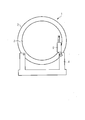
- Figure 1 shows a direct drive generator 1 arranged on a support structure 4.
- An outer rotor 3 of the direct drive generator 1 is fixed to the support structure 4 for handling.
- Actuator means 5, e.g. a hydraulic cylinder are connected to an inner stator 2 of the direct drive generator 1.
- the actuator means 5 of the embodiment shown in Figure 1 could also be connected to the outer rotor 3 instead of the support structure 4, however, connection of the actuator means 5 to the support structure 4 is preferred because the support structure 4 provides more space for suitable connection means than the relatively thin rim of the outer rotor 3.
- the actuator means 4 rotate the inner stator 2 relatively to the outer rotor 3 to avoid the generation of stand still marks.
- the invention may be equally used for direct drive generators having an outer stator and an inner rotor. In this case a first end of the actuator means 5 will connect to the inner rotor and a second end of the actuator means 5 will connect to the outer stator or the support means 4.
- Fig. 2 shows a direct drive generator 1 installed within a nacelle 6 arranged on a support structure 4 which are handled according to a second embodiment of the method of the invention.
- the actuator means 5 are connected to the outer rotor 3 of the direct drive generator 1.
- the inner stator 2 may be fixed to the support structure 4.
- the inner stator 2 may be fastened to the support structure 4 by means of nuts and bolts that extend through corresponding borings in the support structure 4 and a flange of the inner stator 2.
- the nacelle 6 may rest on the support structure 4 or may be affixed to it.
- the invention has an advantage that handling of the direct drive generator 1 e.g. for storing or transportation does not cause any damages to the direct drive generator 1.
Landscapes
- Engineering & Computer Science (AREA)
- Life Sciences & Earth Sciences (AREA)
- Sustainable Development (AREA)
- Sustainable Energy (AREA)
- Chemical & Material Sciences (AREA)
- Combustion & Propulsion (AREA)
- Mechanical Engineering (AREA)
- General Engineering & Computer Science (AREA)
- Power Engineering (AREA)
- Manufacturing & Machinery (AREA)
- Wind Motors (AREA)
- Connection Of Motors, Electrical Generators, Mechanical Devices, And The Like (AREA)
Description
- The invention relates to a method of handling a direct drive generator of a wind turbine and an assembly for handling a direct drive generator of a wind turbine.
- With the increasing demand for renewable energies the typical rated output powers of wind turbines have been growing for many years. The greater output power leads to corresponding increases in the size and weight of the various parts of the wind turbines. Thus, transportation of the parts of the wind turbines has become increasingly difficult. It has been found that rotatable parts of the wind turbines such as bearing may be damaged during transport or storage because of the enormous weight of the individual components. It is known from
EP1611351 to provide an auxiliary device for moving the rotating means of a wind turbine during transportation so as to avoid stand still damages. The damage typically shows as stand still marks where the weight of one component causes deformations to itself or an underlying part. One such part of a wind turbine that may be difficult to handle is a direct drive generator. - The invention therefore provides a method of handling a direct drive generator of a wind turbine. The direct drive generator comprises a stator and a rotor concentrically arranged about an axis of the direct drive generator. The method includes steps of:
- placing the direct drive generator on a support structure;
- fixing a selected one of the stator or the rotor to the support structure;
- connecting actuator means to a remaining one of the stator or the rotor; and
- rotating the remaining one of the stator or the rotor using the actuator means.
- The invention avoids stand still marks by constantly moving or rotating the inner part of the direct drive generator during handling. It should be noted that "rotating" does not necessarily mean rotating the inner part of the direct drive generator by one or more complete revolutions but also motions over only a segment of a circle, e.g. forth and back movements. For example, the outer part of the direct drive generator may rest on the support structure and thereby effectively shields the inner part from any contact with the support structure which may cause damages to the inner part. In this case the inner part of the direct drive generator will be rotated during handling. Furthermore, since the outer part of the direct drive generator does not move relative to the support structure, the outer part will not be damaged either. Thus, the inventive method protects the direct drive generator against damages from stand still marks and from impacts during handling. In addition health and safety risks are eliminated by rotating the inner one of the stator or the rotor because the rotating parts are embedded by the outer one of the stator or the rotor which is fixed to the support structure.
- However, in another preferred embodiment of the method of the invention the inner one of the rotor or the stator is fixed to the support structure while the outer one of the rotor or the stator is rotated during handling. The inner one of the rotor or the stator may be fixed to the support structure by means of a flange or the like that is accessible from the outside of the direct drive generator. The inner one of the rotor or the stator may be propped holding the direct drive generator in such a way that the outer one of the rotor or the stator may be rotated without the support structure interfering. Rotating the outer one is especially useful if the outer one is the rotor of the direct drive generator and the inner one is the stator because the rotor is designed for rotating while the stator may comprise ports or connectors for lubricants for a bearing of the direct drive generator which may be connected to a lubricant reservoir and/or pump included in the support structure. Furthermore, rotating the outer one (e.g. rotor of the direct drive generator) is especially useful when the direct drive generator is already installed within a nacelle of a wind turbine and the direct drive generator and the nacelle are handled together. The nacelle effectively shields the rotor which means that the rotor cannot be damaged or cause damage or harm when rotating during handling.
- Preferably the selected one of the stator or the rotor is the stator of the direct drive generator and the remaining one of the stator or the rotor is the rotor of the direct drive generator. The advantage is that the rotor of the direct derive generator is designed for rotation anyway and, as already mentioned above, the stator may comprise ports and connectors that may be connected to suitable means in the support structure used during handling. Furthermore, the direct drive generator may be handled together with a hub connected to it. In such a case the step of connecting actuator means to the rotor can be carried out by connecting the actuator means to the hub in such a way that the rotor will be rotated by means of rotating the hub.
- Preferably the remaining one of the stator or the rotor is rotated back and forth. As already explained above, such smaller movements are sufficient for avoiding stand still marks. However, rotating the remaining part of the direct drive generator back and forth can be accomplished by less complex means such as a hydraulic cylinder which can expand and contract. The linear motion of the hydraulic cylinder will then be transformed into a rotational movement by the inner part of the direct drive generator. Furthermore, only a relatively small extension and contraction of the actuator means / hydraulic cylinder will be required for a back and forth motion as compared to rotating the remaining one by a plurality of full rotations during handling.
- The step of rotating may include rotating the remaining one of the stator or the rotor during a first time interval and not rotating the remaining one of the stator or the rotor during a second time interval following the first time interval. This procedure can be repeated such that the remaining one of the stator or the rotor is periodically moved thus avoiding stand still marks, for example the remaining one of the stator or the rotor can be rotated for some seconds every ten minutes thus reducing power consumption. The length of the time intervals can be chosen depending on the situation. For example, the rotation can be constantly carried out during e.g. transportation by train while it may be carried out in intervals while being transported on a truck. Furthermore, the length of the time intervals can be chosen depending on the availability of an external power supply for the actuator means, i.e. rotation may be carried out constantly or with relatively shorter pauses when such a power supply is available and with relatively longer pauses when such a power supply is unavailable.
- The method may further comprise connecting the actuator means to the support structure. The connection to the support structure provides a pivotal point for the actuator means.
- The method may further comprise hoisting the support structure with the direct drive generator onto transportation means. The support structure may then be transported together with the direct drive generator while rotating the inner one of the stator or the rotor. Alternatively the support structure may be stored together with the direct drive generator while rotating the inner one of the stator or the rotor. Transportation and storing are the most relevant ways of handling the direct drive generator.
- A second aspect of the invention relates to an assembly for handling a direct drive generator of a wind turbine. The direct drive generator comprises a stator and a rotor concentrically arranged about an axis of the direct drive generator. The assembly includes a support structure adapted to carry the direct drive generator and actuator means adapted to rotate one of the stator or the rotor of the direct drive generator.
- In a preferred embodiment of the invention the actuator means are connected to the support structure. Preferably the actuator means comprise a hydraulic cylinder.
- Further features, properties and advantages of the present invention will become clear from the following description of preferred embodiments in conjunction with the accompanying drawings.
-
Fig. 1 shows a direct drive generator arranged on a support structure according to a first embodiment of the method of the invention; and - Fig. 2 shows a direct drive generator installed within a nacelle arranged on a support structure according to a second embodiment of the method of the invention.
-
Figure 1 shows a direct drive generator 1 arranged on a support structure 4. An outer rotor 3 of the direct drive generator 1 is fixed to the support structure 4 for handling. Thus, the outer rotor 3 cannot move relatively to the support structure 4 thereby avoiding damages to the outer rotor 3 such as scratch marks. Actuator means 5, e.g. a hydraulic cylinder, are connected to aninner stator 2 of the direct drive generator 1. The actuator means 5 of the embodiment shown inFigure 1 could also be connected to the outer rotor 3 instead of the support structure 4, however, connection of the actuator means 5 to the support structure 4 is preferred because the support structure 4 provides more space for suitable connection means than the relatively thin rim of the outer rotor 3. The actuator means 4 rotate theinner stator 2 relatively to the outer rotor 3 to avoid the generation of stand still marks. The invention may be equally used for direct drive generators having an outer stator and an inner rotor. In this case a first end of the actuator means 5 will connect to the inner rotor and a second end of the actuator means 5 will connect to the outer stator or the support means 4. - Fig. 2 shows a direct drive generator 1 installed within a nacelle 6 arranged on a support structure 4 which are handled according to a second embodiment of the method of the invention. Here the actuator means 5 are connected to the outer rotor 3 of the direct drive generator 1. The
inner stator 2 may be fixed to the support structure 4. For example, theinner stator 2 may be fastened to the support structure 4 by means of nuts and bolts that extend through corresponding borings in the support structure 4 and a flange of theinner stator 2. The nacelle 6 may rest on the support structure 4 or may be affixed to it. - The invention has an advantage that handling of the direct drive generator 1 e.g. for storing or transportation does not cause any damages to the direct drive generator 1.
- The present invention has been described with respect to exemplary embodiments thereof which serve as illustrative examples of the invention. However, although specific embodiments have been described to explain the invention, deviations from these embodiments are possible. Hence, the scope of the invention shall not be limited by the described exemplary embodiments but only by the appended claims.
Claims (12)
- A method of handling a direct drive generator (1) of a wind turbine, the direct drive generator (1) comprising a stator (2) and a rotor (3) concentrically arranged about an axis of the direct drive generator (1), wherein the method includes steps of:placing the direct drive generator (1) on a support structure (4);fixing a selected one of the stator (2) or the rotor (3) to the support structure (4);connecting actuator means (5) to a remaining one of the stator (2) or the rotor (3); androtating the remaining one of the stator (2) or the rotor (3) using the actuator means (5).
- The method of the preceding claim, wherein the selected one of the stator (2) or the rotor (3) is an inner one of the stator (2) or the rotor (3) and wherein the remaining one of the stator (2) or the rotor (3) is an outer one of the stator (2) or the rotor (3).
- The method of one of the preceding claims, wherein the selected one of the stator (2) or the rotor (3) is the stator (2) of the direct drive generator (1) and wherein the remaining one of the stator (2) or the rotor (3) is the rotor (3) of the direct drive generator (1).
- The method of one of the preceding claims, wherein the remaining one of the stator (2) or the rotor (3) is rotated back and forth.
- The method of one of the preceding claims, wherein the step of rotating includes rotating the remaining one of the stator (2) or the rotor (3) during a first time interval and not rotating the remaining one of the stator (2) or the rotor (3) during a second time interval following the first time interval.
- The method of one of the preceding claims, further comprising connecting the actuator means (5) to the support structure (4).
- The method of one of the preceding claims, further comprising hoisting the support structure (4) with the direct drive generator (1) onto transportation means.
- The method of the preceding claim, wherein the support structure (4) is transported together with the direct drive generator (1) while rotating the inner one of the stator (2) or the rotor (3).
- The method of one of the claims 1 through 6, wherein the support structure (4) is stored together with the direct drive generator (1) while rotating the inner one of the stator (2) or the rotor (3).
- An assembly for handling a direct drive generator (1) of a wind turbine, the direct drive generator (1) comprising a stator (2) and a rotor (3) concentrically arranged about an axis of the direct drive generator (1), the assembly including a support structure (4) adapted to carry the direct drive generator (1) and actuator means (5) adapted to rotate one of the stator (2) or the rotor (3) of the direct drive generator (1).
- The assembly of claim 10, wherein the actuator means (5) are connected to the support structure (4).
- The assembly of one of the claims 10 or 11, wherein the actuator means (5) comprise a hydraulic cylinder.
Priority Applications (1)
| Application Number | Priority Date | Filing Date | Title |
|---|---|---|---|
| EP13820773.3A EP2909472B1 (en) | 2013-01-07 | 2013-12-23 | Transportation of a direct drive generator |
Applications Claiming Priority (3)
| Application Number | Priority Date | Filing Date | Title |
|---|---|---|---|
| EP13150378 | 2013-01-07 | ||
| EP13820773.3A EP2909472B1 (en) | 2013-01-07 | 2013-12-23 | Transportation of a direct drive generator |
| PCT/EP2013/077872 WO2014106601A1 (en) | 2013-01-07 | 2013-12-23 | Transportation of a direct drive generator |
Publications (2)
| Publication Number | Publication Date |
|---|---|
| EP2909472A1 EP2909472A1 (en) | 2015-08-26 |
| EP2909472B1 true EP2909472B1 (en) | 2016-09-28 |
Family
ID=47720277
Family Applications (1)
| Application Number | Title | Priority Date | Filing Date |
|---|---|---|---|
| EP13820773.3A Active EP2909472B1 (en) | 2013-01-07 | 2013-12-23 | Transportation of a direct drive generator |
Country Status (5)
| Country | Link |
|---|---|
| US (1) | US10145362B2 (en) |
| EP (1) | EP2909472B1 (en) |
| CN (1) | CN104995399B (en) |
| DK (1) | DK2909472T3 (en) |
| WO (1) | WO2014106601A1 (en) |
Cited By (1)
| Publication number | Priority date | Publication date | Assignee | Title |
|---|---|---|---|---|
| EP3620652A1 (en) | 2018-09-06 | 2020-03-11 | Siemens Gamesa Renewable Energy A/S | Treating a wind turbine drive train |
Families Citing this family (2)
| Publication number | Priority date | Publication date | Assignee | Title |
|---|---|---|---|---|
| DE102017127616B3 (en) * | 2017-11-22 | 2019-03-28 | AMK Arnold Müller GmbH & Co. KG | Apparatus and method for the long-term storage of electric motors |
| US11767772B1 (en) | 2022-04-18 | 2023-09-26 | Pratt & Whitney Canada Corp. | Passively rotating a rotating structure of a gas turbine engine during transportation |
Family Cites Families (8)
| Publication number | Priority date | Publication date | Assignee | Title |
|---|---|---|---|---|
| DE3344449C2 (en) | 1983-05-13 | 1986-11-27 | Anton Piller GmbH & Co KG, 3360 Osterode | Standstill protection for the bearings of rotating machines |
| CN100375835C (en) * | 2003-03-21 | 2008-03-19 | 维斯塔斯风力系统有限公司 | Method for moving a rotating means of a wind turbine during transportation or stand still, method for controlling the movement of the rotating means, nacelle, auxiliary device, control and monitoring system and use thereof |
| DE102004013624A1 (en) | 2004-03-19 | 2005-10-06 | Sb Contractor A/S | Method for operating a wind turbine and wind turbine |
| DK2395240T3 (en) * | 2010-06-11 | 2015-11-16 | Siemens Ag | Windkraftanlagen Nacelle, transport to a wind turbines nacelle and method for transporting a wind turbines nacelle |
| EP2434623A1 (en) * | 2010-09-24 | 2012-03-28 | Siemens Aktiengesellschaft | Permanent magnet machine with two stators |
| US8646177B2 (en) * | 2010-12-07 | 2014-02-11 | General Electric Company | Method and apparatus for mounting a rotor blade on a wind turbine |
| DE102011017801B8 (en) | 2011-04-29 | 2013-05-08 | Wobben Properties Gmbh | Wind turbine with a plurality of displacement units for mounting or dismounting of rotor blades and method thereof |
| CN202550828U (en) * | 2012-03-19 | 2012-11-21 | 江苏南车电机有限公司 | Horizontal stator storage tool for large permanent-magnet directly-driven wind power generator |
-
2013
- 2013-12-23 US US14/655,481 patent/US10145362B2/en active Active
- 2013-12-23 EP EP13820773.3A patent/EP2909472B1/en active Active
- 2013-12-23 DK DK13820773.3T patent/DK2909472T3/en active
- 2013-12-23 CN CN201380069678.9A patent/CN104995399B/en active Active
- 2013-12-23 WO PCT/EP2013/077872 patent/WO2014106601A1/en not_active Ceased
Cited By (3)
| Publication number | Priority date | Publication date | Assignee | Title |
|---|---|---|---|---|
| EP3620652A1 (en) | 2018-09-06 | 2020-03-11 | Siemens Gamesa Renewable Energy A/S | Treating a wind turbine drive train |
| WO2020048732A1 (en) * | 2018-09-06 | 2020-03-12 | Siemens Gamesa Renewable Energy A/S | Treating a wind turbine drive train |
| EP3824181B1 (en) | 2018-09-06 | 2023-11-29 | Siemens Gamesa Renewable Energy A/S | Treating a wind turbine drive train |
Also Published As
| Publication number | Publication date |
|---|---|
| CN104995399A (en) | 2015-10-21 |
| US20150361963A1 (en) | 2015-12-17 |
| US10145362B2 (en) | 2018-12-04 |
| CN104995399B (en) | 2018-08-17 |
| WO2014106601A1 (en) | 2014-07-10 |
| EP2909472A1 (en) | 2015-08-26 |
| DK2909472T3 (en) | 2017-01-09 |
Similar Documents
| Publication | Publication Date | Title |
|---|---|---|
| US9982658B2 (en) | Offshore wind turbine, method for constructing offshore wind turbine, and offshore wind power generator | |
| US8164211B2 (en) | Wind turbine generator | |
| US9890763B2 (en) | Counterweighting a wind turbine hub | |
| US11280320B2 (en) | Yaw system for a wind turbine | |
| US9790926B2 (en) | Counterweighting a wind turbine hub | |
| WO2008089763A3 (en) | Method for moving a wind turbine component, such as a wind turbine hub, from a transportation position to a wind turbine assembly position in or on the nacelle, the main shaft or the hub, a handling unit, a wind turbine hub and use hereof | |
| US9103326B2 (en) | Wind turbine bedplate support frame | |
| US8091199B2 (en) | Method to repair pitch control components | |
| US20120114487A1 (en) | Wind turbine generator | |
| US10443572B2 (en) | System and method for removing or installing a main shaft of a wind turbine | |
| EP2604851A2 (en) | A wind turbine nacelle cover and a method for installing a generator on a mainframe in a nacelle | |
| US10788015B2 (en) | Method of handling a wind turbine rotor blade pitch bearing unit | |
| EP2909472B1 (en) | Transportation of a direct drive generator | |
| US7811057B2 (en) | Methods and apparatus to facilitate lubrication of components | |
| CN105298754A (en) | Wind driven generator and wind driven generator set | |
| CN105649885B (en) | Wind turbine, wind turbine and installation method thereof | |
| US20180038350A1 (en) | Adapters for wind turbine refurbishment | |
| US20190293053A1 (en) | Methods and Apparatus for Refurbishing Wind Turbine Foundations | |
| CN105209751A (en) | Blade angle control apparatus of wind power generator and wind power generator having same | |
| US20180238308A1 (en) | System and Method for Removal of a Wind Turbine Gearbox from a Main Rotor Shaft | |
| CN205101174U (en) | Wind -driven generator and wind -driven generator set | |
| US11174845B2 (en) | Assembly system for assembling of a first wind turbine component of a wind turbine and second wind turbine component of the wind turbine and method for assembling of a wind turbine by using the assembly system | |
| EP3795822B1 (en) | Rotor hub supporting tool, wind power plant head and method for supporting a rotor hub of a wind driven power plant | |
| US9140232B2 (en) | Method for repairing a pitch system in a wind turbine | |
| KR101691068B1 (en) | Protector for offshore structure |
Legal Events
| Date | Code | Title | Description |
|---|---|---|---|
| PUAI | Public reference made under article 153(3) epc to a published international application that has entered the european phase |
Free format text: ORIGINAL CODE: 0009012 |
|
| 17P | Request for examination filed |
Effective date: 20150507 |
|
| AK | Designated contracting states |
Kind code of ref document: A1 Designated state(s): AL AT BE BG CH CY CZ DE DK EE ES FI FR GB GR HR HU IE IS IT LI LT LU LV MC MK MT NL NO PL PT RO RS SE SI SK SM TR |
|
| AX | Request for extension of the european patent |
Extension state: BA ME |
|
| REG | Reference to a national code |
Ref country code: DE Ref legal event code: R079 Ref document number: 602013012288 Country of ref document: DE Free format text: PREVIOUS MAIN CLASS: F03D0001000000 Ipc: F03D0013400000 |
|
| DAX | Request for extension of the european patent (deleted) | ||
| RIC1 | Information provided on ipc code assigned before grant |
Ipc: F03D 15/20 20160101ALI20160314BHEP Ipc: H02K 15/00 20060101ALI20160314BHEP Ipc: F03D 13/40 20160101AFI20160314BHEP |
|
| GRAP | Despatch of communication of intention to grant a patent |
Free format text: ORIGINAL CODE: EPIDOSNIGR1 |
|
| INTG | Intention to grant announced |
Effective date: 20160503 |
|
| GRAS | Grant fee paid |
Free format text: ORIGINAL CODE: EPIDOSNIGR3 |
|
| GRAA | (expected) grant |
Free format text: ORIGINAL CODE: 0009210 |
|
| AK | Designated contracting states |
Kind code of ref document: B1 Designated state(s): AL AT BE BG CH CY CZ DE DK EE ES FI FR GB GR HR HU IE IS IT LI LT LU LV MC MK MT NL NO PL PT RO RS SE SI SK SM TR |
|
| REG | Reference to a national code |
Ref country code: GB Ref legal event code: FG4D |
|
| REG | Reference to a national code |
Ref country code: CH Ref legal event code: EP |
|
| REG | Reference to a national code |
Ref country code: AT Ref legal event code: REF Ref document number: 833006 Country of ref document: AT Kind code of ref document: T Effective date: 20161015 |
|
| REG | Reference to a national code |
Ref country code: IE Ref legal event code: FG4D |
|
| REG | Reference to a national code |
Ref country code: DE Ref legal event code: R096 Ref document number: 602013012288 Country of ref document: DE |
|
| REG | Reference to a national code |
Ref country code: FR Ref legal event code: PLFP Year of fee payment: 4 |
|
| REG | Reference to a national code |
Ref country code: DK Ref legal event code: T3 Effective date: 20170102 |
|
| REG | Reference to a national code |
Ref country code: LT Ref legal event code: MG4D |
|
| PG25 | Lapsed in a contracting state [announced via postgrant information from national office to epo] |
Ref country code: LT Free format text: LAPSE BECAUSE OF FAILURE TO SUBMIT A TRANSLATION OF THE DESCRIPTION OR TO PAY THE FEE WITHIN THE PRESCRIBED TIME-LIMIT Effective date: 20160928 Ref country code: RS Free format text: LAPSE BECAUSE OF FAILURE TO SUBMIT A TRANSLATION OF THE DESCRIPTION OR TO PAY THE FEE WITHIN THE PRESCRIBED TIME-LIMIT Effective date: 20160928 Ref country code: HR Free format text: LAPSE BECAUSE OF FAILURE TO SUBMIT A TRANSLATION OF THE DESCRIPTION OR TO PAY THE FEE WITHIN THE PRESCRIBED TIME-LIMIT Effective date: 20160928 Ref country code: NO Free format text: LAPSE BECAUSE OF FAILURE TO SUBMIT A TRANSLATION OF THE DESCRIPTION OR TO PAY THE FEE WITHIN THE PRESCRIBED TIME-LIMIT Effective date: 20161228 Ref country code: FI Free format text: LAPSE BECAUSE OF FAILURE TO SUBMIT A TRANSLATION OF THE DESCRIPTION OR TO PAY THE FEE WITHIN THE PRESCRIBED TIME-LIMIT Effective date: 20160928 |
|
| REG | Reference to a national code |
Ref country code: NL Ref legal event code: MP Effective date: 20160928 |
|
| REG | Reference to a national code |
Ref country code: AT Ref legal event code: MK05 Ref document number: 833006 Country of ref document: AT Kind code of ref document: T Effective date: 20160928 |
|
| PG25 | Lapsed in a contracting state [announced via postgrant information from national office to epo] |
Ref country code: NL Free format text: LAPSE BECAUSE OF FAILURE TO SUBMIT A TRANSLATION OF THE DESCRIPTION OR TO PAY THE FEE WITHIN THE PRESCRIBED TIME-LIMIT Effective date: 20160928 Ref country code: SE Free format text: LAPSE BECAUSE OF FAILURE TO SUBMIT A TRANSLATION OF THE DESCRIPTION OR TO PAY THE FEE WITHIN THE PRESCRIBED TIME-LIMIT Effective date: 20160928 Ref country code: GR Free format text: LAPSE BECAUSE OF FAILURE TO SUBMIT A TRANSLATION OF THE DESCRIPTION OR TO PAY THE FEE WITHIN THE PRESCRIBED TIME-LIMIT Effective date: 20161229 Ref country code: LV Free format text: LAPSE BECAUSE OF FAILURE TO SUBMIT A TRANSLATION OF THE DESCRIPTION OR TO PAY THE FEE WITHIN THE PRESCRIBED TIME-LIMIT Effective date: 20160928 |
|
| PG25 | Lapsed in a contracting state [announced via postgrant information from national office to epo] |
Ref country code: EE Free format text: LAPSE BECAUSE OF FAILURE TO SUBMIT A TRANSLATION OF THE DESCRIPTION OR TO PAY THE FEE WITHIN THE PRESCRIBED TIME-LIMIT Effective date: 20160928 Ref country code: RO Free format text: LAPSE BECAUSE OF FAILURE TO SUBMIT A TRANSLATION OF THE DESCRIPTION OR TO PAY THE FEE WITHIN THE PRESCRIBED TIME-LIMIT Effective date: 20160928 |
|
| PG25 | Lapsed in a contracting state [announced via postgrant information from national office to epo] |
Ref country code: AT Free format text: LAPSE BECAUSE OF FAILURE TO SUBMIT A TRANSLATION OF THE DESCRIPTION OR TO PAY THE FEE WITHIN THE PRESCRIBED TIME-LIMIT Effective date: 20160928 Ref country code: BG Free format text: LAPSE BECAUSE OF FAILURE TO SUBMIT A TRANSLATION OF THE DESCRIPTION OR TO PAY THE FEE WITHIN THE PRESCRIBED TIME-LIMIT Effective date: 20161228 Ref country code: SK Free format text: LAPSE BECAUSE OF FAILURE TO SUBMIT A TRANSLATION OF THE DESCRIPTION OR TO PAY THE FEE WITHIN THE PRESCRIBED TIME-LIMIT Effective date: 20160928 Ref country code: PL Free format text: LAPSE BECAUSE OF FAILURE TO SUBMIT A TRANSLATION OF THE DESCRIPTION OR TO PAY THE FEE WITHIN THE PRESCRIBED TIME-LIMIT Effective date: 20160928 Ref country code: PT Free format text: LAPSE BECAUSE OF FAILURE TO SUBMIT A TRANSLATION OF THE DESCRIPTION OR TO PAY THE FEE WITHIN THE PRESCRIBED TIME-LIMIT Effective date: 20170130 Ref country code: SM Free format text: LAPSE BECAUSE OF FAILURE TO SUBMIT A TRANSLATION OF THE DESCRIPTION OR TO PAY THE FEE WITHIN THE PRESCRIBED TIME-LIMIT Effective date: 20160928 Ref country code: ES Free format text: LAPSE BECAUSE OF FAILURE TO SUBMIT A TRANSLATION OF THE DESCRIPTION OR TO PAY THE FEE WITHIN THE PRESCRIBED TIME-LIMIT Effective date: 20160928 Ref country code: CZ Free format text: LAPSE BECAUSE OF FAILURE TO SUBMIT A TRANSLATION OF THE DESCRIPTION OR TO PAY THE FEE WITHIN THE PRESCRIBED TIME-LIMIT Effective date: 20160928 Ref country code: BE Free format text: LAPSE BECAUSE OF FAILURE TO SUBMIT A TRANSLATION OF THE DESCRIPTION OR TO PAY THE FEE WITHIN THE PRESCRIBED TIME-LIMIT Effective date: 20160928 Ref country code: IS Free format text: LAPSE BECAUSE OF FAILURE TO SUBMIT A TRANSLATION OF THE DESCRIPTION OR TO PAY THE FEE WITHIN THE PRESCRIBED TIME-LIMIT Effective date: 20170128 |
|
| REG | Reference to a national code |
Ref country code: DE Ref legal event code: R097 Ref document number: 602013012288 Country of ref document: DE |
|
| PG25 | Lapsed in a contracting state [announced via postgrant information from national office to epo] |
Ref country code: IT Free format text: LAPSE BECAUSE OF FAILURE TO SUBMIT A TRANSLATION OF THE DESCRIPTION OR TO PAY THE FEE WITHIN THE PRESCRIBED TIME-LIMIT Effective date: 20160928 |
|
| REG | Reference to a national code |
Ref country code: CH Ref legal event code: PL |
|
| PLBE | No opposition filed within time limit |
Free format text: ORIGINAL CODE: 0009261 |
|
| STAA | Information on the status of an ep patent application or granted ep patent |
Free format text: STATUS: NO OPPOSITION FILED WITHIN TIME LIMIT |
|
| RAP2 | Party data changed (patent owner data changed or rights of a patent transferred) |
Owner name: SIEMENS AKTIENGESELLSCHAFT |
|
| 26N | No opposition filed |
Effective date: 20170629 |
|
| PG25 | Lapsed in a contracting state [announced via postgrant information from national office to epo] |
Ref country code: MC Free format text: LAPSE BECAUSE OF FAILURE TO SUBMIT A TRANSLATION OF THE DESCRIPTION OR TO PAY THE FEE WITHIN THE PRESCRIBED TIME-LIMIT Effective date: 20160928 |
|
| REG | Reference to a national code |
Ref country code: IE Ref legal event code: MM4A |
|
| PG25 | Lapsed in a contracting state [announced via postgrant information from national office to epo] |
Ref country code: CH Free format text: LAPSE BECAUSE OF NON-PAYMENT OF DUE FEES Effective date: 20161231 Ref country code: LU Free format text: LAPSE BECAUSE OF NON-PAYMENT OF DUE FEES Effective date: 20161223 Ref country code: LI Free format text: LAPSE BECAUSE OF NON-PAYMENT OF DUE FEES Effective date: 20161231 |
|
| PG25 | Lapsed in a contracting state [announced via postgrant information from national office to epo] |
Ref country code: SI Free format text: LAPSE BECAUSE OF FAILURE TO SUBMIT A TRANSLATION OF THE DESCRIPTION OR TO PAY THE FEE WITHIN THE PRESCRIBED TIME-LIMIT Effective date: 20160928 Ref country code: IE Free format text: LAPSE BECAUSE OF NON-PAYMENT OF DUE FEES Effective date: 20161223 |
|
| REG | Reference to a national code |
Ref country code: FR Ref legal event code: PLFP Year of fee payment: 5 |
|
| PG25 | Lapsed in a contracting state [announced via postgrant information from national office to epo] |
Ref country code: HU Free format text: LAPSE BECAUSE OF FAILURE TO SUBMIT A TRANSLATION OF THE DESCRIPTION OR TO PAY THE FEE WITHIN THE PRESCRIBED TIME-LIMIT; INVALID AB INITIO Effective date: 20131223 |
|
| PG25 | Lapsed in a contracting state [announced via postgrant information from national office to epo] |
Ref country code: CY Free format text: LAPSE BECAUSE OF FAILURE TO SUBMIT A TRANSLATION OF THE DESCRIPTION OR TO PAY THE FEE WITHIN THE PRESCRIBED TIME-LIMIT Effective date: 20160928 Ref country code: MK Free format text: LAPSE BECAUSE OF FAILURE TO SUBMIT A TRANSLATION OF THE DESCRIPTION OR TO PAY THE FEE WITHIN THE PRESCRIBED TIME-LIMIT Effective date: 20160928 |
|
| PG25 | Lapsed in a contracting state [announced via postgrant information from national office to epo] |
Ref country code: MT Free format text: LAPSE BECAUSE OF NON-PAYMENT OF DUE FEES Effective date: 20161223 |
|
| PG25 | Lapsed in a contracting state [announced via postgrant information from national office to epo] |
Ref country code: TR Free format text: LAPSE BECAUSE OF FAILURE TO SUBMIT A TRANSLATION OF THE DESCRIPTION OR TO PAY THE FEE WITHIN THE PRESCRIBED TIME-LIMIT Effective date: 20160928 Ref country code: AL Free format text: LAPSE BECAUSE OF FAILURE TO SUBMIT A TRANSLATION OF THE DESCRIPTION OR TO PAY THE FEE WITHIN THE PRESCRIBED TIME-LIMIT Effective date: 20160928 |
|
| REG | Reference to a national code |
Ref country code: DE Ref legal event code: R081 Ref document number: 602013012288 Country of ref document: DE Owner name: SIEMENS GAMESA RENEWABLE ENERGY A/S, DK Free format text: FORMER OWNER: SIEMENS AKTIENGESELLSCHAFT, 80333 MUENCHEN, DE |
|
| REG | Reference to a national code |
Ref country code: GB Ref legal event code: 732E Free format text: REGISTERED BETWEEN 20191128 AND 20191204 |
|
| PGFP | Annual fee paid to national office [announced via postgrant information from national office to epo] |
Ref country code: DK Payment date: 20250912 Year of fee payment: 13 |
|
| PGFP | Annual fee paid to national office [announced via postgrant information from national office to epo] |
Ref country code: DE Payment date: 20250731 Year of fee payment: 13 |
|
| PGFP | Annual fee paid to national office [announced via postgrant information from national office to epo] |
Ref country code: GB Payment date: 20251223 Year of fee payment: 13 |
|
| PGFP | Annual fee paid to national office [announced via postgrant information from national office to epo] |
Ref country code: FR Payment date: 20251223 Year of fee payment: 13 |