EP2909472B1 - Transport eines direktantriebsgenerators - Google Patents
Transport eines direktantriebsgenerators Download PDFInfo
- Publication number
- EP2909472B1 EP2909472B1 EP13820773.3A EP13820773A EP2909472B1 EP 2909472 B1 EP2909472 B1 EP 2909472B1 EP 13820773 A EP13820773 A EP 13820773A EP 2909472 B1 EP2909472 B1 EP 2909472B1
- Authority
- EP
- European Patent Office
- Prior art keywords
- rotor
- stator
- direct drive
- drive generator
- support structure
- Prior art date
- Legal status (The legal status is an assumption and is not a legal conclusion. Google has not performed a legal analysis and makes no representation as to the accuracy of the status listed.)
- Active
Links
Images
Classifications
-
- F—MECHANICAL ENGINEERING; LIGHTING; HEATING; WEAPONS; BLASTING
- F03—MACHINES OR ENGINES FOR LIQUIDS; WIND, SPRING, OR WEIGHT MOTORS; PRODUCING MECHANICAL POWER OR A REACTIVE PROPULSIVE THRUST, NOT OTHERWISE PROVIDED FOR
- F03D—WIND MOTORS
- F03D80/00—Details, components or accessories not provided for in groups F03D1/00 - F03D17/00
-
- F—MECHANICAL ENGINEERING; LIGHTING; HEATING; WEAPONS; BLASTING
- F03—MACHINES OR ENGINES FOR LIQUIDS; WIND, SPRING, OR WEIGHT MOTORS; PRODUCING MECHANICAL POWER OR A REACTIVE PROPULSIVE THRUST, NOT OTHERWISE PROVIDED FOR
- F03D—WIND MOTORS
- F03D13/00—Assembly, mounting or commissioning of wind motors; Arrangements specially adapted for transporting wind motor components
- F03D13/40—Arrangements or methods specially adapted for transporting wind motor components
-
- F—MECHANICAL ENGINEERING; LIGHTING; HEATING; WEAPONS; BLASTING
- F03—MACHINES OR ENGINES FOR LIQUIDS; WIND, SPRING, OR WEIGHT MOTORS; PRODUCING MECHANICAL POWER OR A REACTIVE PROPULSIVE THRUST, NOT OTHERWISE PROVIDED FOR
- F03D—WIND MOTORS
- F03D13/00—Assembly, mounting or commissioning of wind motors; Arrangements specially adapted for transporting wind motor components
- F03D13/10—Assembly of wind motors; Arrangements for erecting wind motors
-
- F—MECHANICAL ENGINEERING; LIGHTING; HEATING; WEAPONS; BLASTING
- F03—MACHINES OR ENGINES FOR LIQUIDS; WIND, SPRING, OR WEIGHT MOTORS; PRODUCING MECHANICAL POWER OR A REACTIVE PROPULSIVE THRUST, NOT OTHERWISE PROVIDED FOR
- F03D—WIND MOTORS
- F03D15/00—Transmission of mechanical power
- F03D15/20—Gearless transmission, i.e. direct-drive
-
- F—MECHANICAL ENGINEERING; LIGHTING; HEATING; WEAPONS; BLASTING
- F03—MACHINES OR ENGINES FOR LIQUIDS; WIND, SPRING, OR WEIGHT MOTORS; PRODUCING MECHANICAL POWER OR A REACTIVE PROPULSIVE THRUST, NOT OTHERWISE PROVIDED FOR
- F03D—WIND MOTORS
- F03D80/00—Details, components or accessories not provided for in groups F03D1/00 - F03D17/00
- F03D80/80—Arrangement of components within nacelles or towers
- F03D80/82—Arrangement of components within nacelles or towers of electrical components
-
- F—MECHANICAL ENGINEERING; LIGHTING; HEATING; WEAPONS; BLASTING
- F03—MACHINES OR ENGINES FOR LIQUIDS; WIND, SPRING, OR WEIGHT MOTORS; PRODUCING MECHANICAL POWER OR A REACTIVE PROPULSIVE THRUST, NOT OTHERWISE PROVIDED FOR
- F03D—WIND MOTORS
- F03D80/00—Details, components or accessories not provided for in groups F03D1/00 - F03D17/00
- F03D80/80—Arrangement of components within nacelles or towers
- F03D80/88—Arrangement of components within nacelles or towers of mechanical components
-
- F—MECHANICAL ENGINEERING; LIGHTING; HEATING; WEAPONS; BLASTING
- F03—MACHINES OR ENGINES FOR LIQUIDS; WIND, SPRING, OR WEIGHT MOTORS; PRODUCING MECHANICAL POWER OR A REACTIVE PROPULSIVE THRUST, NOT OTHERWISE PROVIDED FOR
- F03D—WIND MOTORS
- F03D9/00—Adaptations of wind motors for special use; Combinations of wind motors with apparatus driven thereby; Wind motors specially adapted for installation in particular locations
- F03D9/20—Wind motors characterised by the driven apparatus
- F03D9/25—Wind motors characterised by the driven apparatus the apparatus being an electrical generator
-
- H—ELECTRICITY
- H02—GENERATION; CONVERSION OR DISTRIBUTION OF ELECTRIC POWER
- H02K—DYNAMO-ELECTRIC MACHINES
- H02K15/00—Processes or apparatus specially adapted for manufacturing, assembling, maintaining or repairing of dynamo-electric machines
-
- F—MECHANICAL ENGINEERING; LIGHTING; HEATING; WEAPONS; BLASTING
- F05—INDEXING SCHEMES RELATING TO ENGINES OR PUMPS IN VARIOUS SUBCLASSES OF CLASSES F01-F04
- F05B—INDEXING SCHEME RELATING TO WIND, SPRING, WEIGHT, INERTIA OR LIKE MOTORS, TO MACHINES OR ENGINES FOR LIQUIDS COVERED BY SUBCLASSES F03B, F03D AND F03G
- F05B2220/00—Application
- F05B2220/70—Application in combination with
- F05B2220/706—Application in combination with an electrical generator
- F05B2220/7066—Application in combination with an electrical generator via a direct connection, i.e. a gearless transmission
-
- Y—GENERAL TAGGING OF NEW TECHNOLOGICAL DEVELOPMENTS; GENERAL TAGGING OF CROSS-SECTIONAL TECHNOLOGIES SPANNING OVER SEVERAL SECTIONS OF THE IPC; TECHNICAL SUBJECTS COVERED BY FORMER USPC CROSS-REFERENCE ART COLLECTIONS [XRACs] AND DIGESTS
- Y02—TECHNOLOGIES OR APPLICATIONS FOR MITIGATION OR ADAPTATION AGAINST CLIMATE CHANGE
- Y02E—REDUCTION OF GREENHOUSE GAS [GHG] EMISSIONS, RELATED TO ENERGY GENERATION, TRANSMISSION OR DISTRIBUTION
- Y02E10/00—Energy generation through renewable energy sources
- Y02E10/70—Wind energy
- Y02E10/72—Wind turbines with rotation axis in wind direction
-
- Y—GENERAL TAGGING OF NEW TECHNOLOGICAL DEVELOPMENTS; GENERAL TAGGING OF CROSS-SECTIONAL TECHNOLOGIES SPANNING OVER SEVERAL SECTIONS OF THE IPC; TECHNICAL SUBJECTS COVERED BY FORMER USPC CROSS-REFERENCE ART COLLECTIONS [XRACs] AND DIGESTS
- Y10—TECHNICAL SUBJECTS COVERED BY FORMER USPC
- Y10T—TECHNICAL SUBJECTS COVERED BY FORMER US CLASSIFICATION
- Y10T29/00—Metal working
- Y10T29/49—Method of mechanical manufacture
- Y10T29/49826—Assembling or joining
- Y10T29/49828—Progressively advancing of work assembly station or assembled portion of work
Definitions
- the invention relates to a method of handling a direct drive generator of a wind turbine and an assembly for handling a direct drive generator of a wind turbine.
- the invention therefore provides a method of handling a direct drive generator of a wind turbine.
- the direct drive generator comprises a stator and a rotor concentrically arranged about an axis of the direct drive generator.
- the method includes steps of:
- the invention avoids stand still marks by constantly moving or rotating the inner part of the direct drive generator during handling.
- rotating does not necessarily mean rotating the inner part of the direct drive generator by one or more complete revolutions but also motions over only a segment of a circle, e.g. forth and back movements.
- the outer part of the direct drive generator may rest on the support structure and thereby effectively shields the inner part from any contact with the support structure which may cause damages to the inner part.
- the inner part of the direct drive generator will be rotated during handling.
- the outer part of the direct drive generator does not move relative to the support structure, the outer part will not be damaged either.
- the inventive method protects the direct drive generator against damages from stand still marks and from impacts during handling.
- health and safety risks are eliminated by rotating the inner one of the stator or the rotor because the rotating parts are embedded by the outer one of the stator or the rotor which is fixed to the support structure.
- the inner one of the rotor or the stator is fixed to the support structure while the outer one of the rotor or the stator is rotated during handling.
- the inner one of the rotor or the stator may be fixed to the support structure by means of a flange or the like that is accessible from the outside of the direct drive generator.
- the inner one of the rotor or the stator may be propped holding the direct drive generator in such a way that the outer one of the rotor or the stator may be rotated without the support structure interfering.
- Rotating the outer one is especially useful if the outer one is the rotor of the direct drive generator and the inner one is the stator because the rotor is designed for rotating while the stator may comprise ports or connectors for lubricants for a bearing of the direct drive generator which may be connected to a lubricant reservoir and/or pump included in the support structure. Furthermore, rotating the outer one (e.g. rotor of the direct drive generator) is especially useful when the direct drive generator is already installed within a nacelle of a wind turbine and the direct drive generator and the nacelle are handled together. The nacelle effectively shields the rotor which means that the rotor cannot be damaged or cause damage or harm when rotating during handling.
- the selected one of the stator or the rotor is the stator of the direct drive generator and the remaining one of the stator or the rotor is the rotor of the direct drive generator.
- the rotor of the direct derive generator is designed for rotation anyway and, as already mentioned above, the stator may comprise ports and connectors that may be connected to suitable means in the support structure used during handling.
- the direct drive generator may be handled together with a hub connected to it. In such a case the step of connecting actuator means to the rotor can be carried out by connecting the actuator means to the hub in such a way that the rotor will be rotated by means of rotating the hub.
- the remaining one of the stator or the rotor is rotated back and forth.
- rotating the remaining part of the direct drive generator back and forth can be accomplished by less complex means such as a hydraulic cylinder which can expand and contract.
- the linear motion of the hydraulic cylinder will then be transformed into a rotational movement by the inner part of the direct drive generator.
- only a relatively small extension and contraction of the actuator means / hydraulic cylinder will be required for a back and forth motion as compared to rotating the remaining one by a plurality of full rotations during handling.
- the step of rotating may include rotating the remaining one of the stator or the rotor during a first time interval and not rotating the remaining one of the stator or the rotor during a second time interval following the first time interval. This procedure can be repeated such that the remaining one of the stator or the rotor is periodically moved thus avoiding stand still marks, for example the remaining one of the stator or the rotor can be rotated for some seconds every ten minutes thus reducing power consumption.
- the length of the time intervals can be chosen depending on the situation.
- the rotation can be constantly carried out during e.g. transportation by train while it may be carried out in intervals while being transported on a truck.
- the length of the time intervals can be chosen depending on the availability of an external power supply for the actuator means, i.e. rotation may be carried out constantly or with relatively shorter pauses when such a power supply is available and with relatively longer pauses when such a power supply is unavailable.
- the method may further comprise connecting the actuator means to the support structure.
- the connection to the support structure provides a pivotal point for the actuator means.
- the method may further comprise hoisting the support structure with the direct drive generator onto transportation means.
- the support structure may then be transported together with the direct drive generator while rotating the inner one of the stator or the rotor.
- the support structure may be stored together with the direct drive generator while rotating the inner one of the stator or the rotor.
- Transportation and storing are the most relevant ways of handling the direct drive generator.
- a second aspect of the invention relates to an assembly for handling a direct drive generator of a wind turbine.
- the direct drive generator comprises a stator and a rotor concentrically arranged about an axis of the direct drive generator.
- the assembly includes a support structure adapted to carry the direct drive generator and actuator means adapted to rotate one of the stator or the rotor of the direct drive generator.
- the actuator means are connected to the support structure.
- the actuator means comprise a hydraulic cylinder.
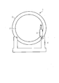
- Figure 1 shows a direct drive generator 1 arranged on a support structure 4.
- An outer rotor 3 of the direct drive generator 1 is fixed to the support structure 4 for handling.
- Actuator means 5, e.g. a hydraulic cylinder are connected to an inner stator 2 of the direct drive generator 1.
- the actuator means 5 of the embodiment shown in Figure 1 could also be connected to the outer rotor 3 instead of the support structure 4, however, connection of the actuator means 5 to the support structure 4 is preferred because the support structure 4 provides more space for suitable connection means than the relatively thin rim of the outer rotor 3.
- the actuator means 4 rotate the inner stator 2 relatively to the outer rotor 3 to avoid the generation of stand still marks.
- the invention may be equally used for direct drive generators having an outer stator and an inner rotor. In this case a first end of the actuator means 5 will connect to the inner rotor and a second end of the actuator means 5 will connect to the outer stator or the support means 4.
- Fig. 2 shows a direct drive generator 1 installed within a nacelle 6 arranged on a support structure 4 which are handled according to a second embodiment of the method of the invention.
- the actuator means 5 are connected to the outer rotor 3 of the direct drive generator 1.
- the inner stator 2 may be fixed to the support structure 4.
- the inner stator 2 may be fastened to the support structure 4 by means of nuts and bolts that extend through corresponding borings in the support structure 4 and a flange of the inner stator 2.
- the nacelle 6 may rest on the support structure 4 or may be affixed to it.
- the invention has an advantage that handling of the direct drive generator 1 e.g. for storing or transportation does not cause any damages to the direct drive generator 1.
Landscapes
- Engineering & Computer Science (AREA)
- Life Sciences & Earth Sciences (AREA)
- Sustainable Development (AREA)
- Sustainable Energy (AREA)
- Chemical & Material Sciences (AREA)
- Combustion & Propulsion (AREA)
- Mechanical Engineering (AREA)
- General Engineering & Computer Science (AREA)
- Power Engineering (AREA)
- Manufacturing & Machinery (AREA)
- Wind Motors (AREA)
- Connection Of Motors, Electrical Generators, Mechanical Devices, And The Like (AREA)
Claims (12)
- Verfahren zur Handhabung eines direktangetriebenen Generators (1) einer Windenergieanlage, der einen Stator (2) und einen Rotor (3) umfasst, die konzentrisch um eine Achse des direktangetriebenen Generators (1) angeordnet sind, wobei das Verfahren folgende Schritte aufweist:Platzieren des direktangetriebenen Generators (1) auf einer Trägerkonstruktion (4),Befestigen des Stators (2) oder des Rotors (3) an der Trägerkonstruktion (4),Verbinden von Stellmitteln (5) mit dem anderen Element, also dem Rotor (3) oder dem Stator (2), undDrehen des anderen Elements, also des Rotors (3) oder des Stators (2), unter Verwendung der Stellmittel (5).
- Verfahren nach dem vorhergehenden Anspruch, bei dem es sich bei dem Stator (2) oder dem Rotor (3) um einen innenliegenden Stator (2) oder Rotor (3) und bei dem anderen Element, also dem Rotor (3) oder dem Stator (2), um einen außenliegenden Rotor (3) oder Stator (2) handelt.
- Verfahren nach einem der vorhergehenden Ansprüche, bei dem es sich bei dem Stator (2) oder dem Rotor (3) um den Stator (2) des direktangetriebenen Generators (1) und bei dem anderen Element, also dem Rotor (3) oder dem Stator (2), um den Rotor (3) des direktangetriebenen Generators (1) handelt.
- Verfahren nach einem der vorhergehenden Ansprüche, bei dem das andere Element, also der Rotor (3) oder der Stator (2), rückwärts und vorwärts gedreht wird.
- Verfahren nach einem der vorhergehenden Ansprüche, bei dem das Drehen das Drehen des anderen Elements, also des Rotors (3) oder des Stators (2), in einem ersten Zeitintervall und das Nichtdrehen des anderen Elements, also des Rotors (3) oder des Stators (2), in einem zweiten Zeitintervall umfasst, das auf das erste Zeitintervall folgt.
- Verfahren nach einem der vorhergehenden Ansprüche, das ferner das Verbinden der Stellmittel (5) mit der Trägerkonstruktion (4) umfasst.
- Verfahren nach einem der vorhergehenden Ansprüche, das ferner das Anheben der Trägerkonstruktion (4) mit dem direktangetriebenen Generator (1) auf Transportmittel umfasst.
- Verfahren nach dem vorhergehenden Anspruch, bei dem die Trägerkonstruktion (4) zusammen mit dem direktangetriebenen Generator (1) transportiert wird, während der innenliegende Stator (2) oder Rotor (3) gedreht wird.
- Verfahren nach einem der Ansprüche 1 bis 6, bei dem die Trägerkonstruktion (4) zusammen mit dem direktangetriebenen Generator (1) eingelagert wird, während der innenliegende Stator (2) oder Rotor (3) gedreht wird.
- Baugruppe zur Handhabung eines direktangetriebenen Generators (1) einer Windenergieanlage, der einen Stator (2) und einen Rotor (3) umfasst, die konzentrisch um eine Achse des direktangetriebenen Generators (1) angeordnet sind, wobei die Baugruppe eine Trägerkonstruktion (4), die so ausgelegt ist, dass sie den direktangetriebenen Generator (1) trägt, und Stellmittel (5) aufweist, die so ausgelegt sind, dass sie den Stator (2) oder den Rotor (3) des direktangetriebenen Generators (1) drehen.
- Baugruppe nach Anspruch 10, bei der die Stellmittel (5) mit der Trägerkonstruktion (4) verbunden sind.
- Baugruppe nach Anspruch 10 oder 11, bei der die Stellmittel (5) einen Hydraulikzylinder umfassen.
Priority Applications (1)
| Application Number | Priority Date | Filing Date | Title |
|---|---|---|---|
| EP13820773.3A EP2909472B1 (de) | 2013-01-07 | 2013-12-23 | Transport eines direktantriebsgenerators |
Applications Claiming Priority (3)
| Application Number | Priority Date | Filing Date | Title |
|---|---|---|---|
| EP13150378 | 2013-01-07 | ||
| EP13820773.3A EP2909472B1 (de) | 2013-01-07 | 2013-12-23 | Transport eines direktantriebsgenerators |
| PCT/EP2013/077872 WO2014106601A1 (en) | 2013-01-07 | 2013-12-23 | Transportation of a direct drive generator |
Publications (2)
| Publication Number | Publication Date |
|---|---|
| EP2909472A1 EP2909472A1 (de) | 2015-08-26 |
| EP2909472B1 true EP2909472B1 (de) | 2016-09-28 |
Family
ID=47720277
Family Applications (1)
| Application Number | Title | Priority Date | Filing Date |
|---|---|---|---|
| EP13820773.3A Active EP2909472B1 (de) | 2013-01-07 | 2013-12-23 | Transport eines direktantriebsgenerators |
Country Status (5)
| Country | Link |
|---|---|
| US (1) | US10145362B2 (de) |
| EP (1) | EP2909472B1 (de) |
| CN (1) | CN104995399B (de) |
| DK (1) | DK2909472T3 (de) |
| WO (1) | WO2014106601A1 (de) |
Cited By (1)
| Publication number | Priority date | Publication date | Assignee | Title |
|---|---|---|---|---|
| EP3620652A1 (de) | 2018-09-06 | 2020-03-11 | Siemens Gamesa Renewable Energy A/S | Behandlung eines antriebsstrangs einer windturbine |
Families Citing this family (2)
| Publication number | Priority date | Publication date | Assignee | Title |
|---|---|---|---|---|
| DE102017127616B3 (de) * | 2017-11-22 | 2019-03-28 | AMK Arnold Müller GmbH & Co. KG | Vorrichtung und Verfahren zur Langfristlagerung von Elektromotoren |
| US11767772B1 (en) | 2022-04-18 | 2023-09-26 | Pratt & Whitney Canada Corp. | Passively rotating a rotating structure of a gas turbine engine during transportation |
Family Cites Families (8)
| Publication number | Priority date | Publication date | Assignee | Title |
|---|---|---|---|---|
| DE3344449C2 (de) | 1983-05-13 | 1986-11-27 | Anton Piller GmbH & Co KG, 3360 Osterode | Stillstandssicherung für die Lager rotierender Maschinen |
| CN100375835C (zh) * | 2003-03-21 | 2008-03-19 | 维斯塔斯风力系统有限公司 | 在运输或静止期间使风轮机的旋转装置运动的方法、控制该旋转装置的运动的方法、引擎舱、辅助装置、控制和监控系统及其应用 |
| DE102004013624A1 (de) | 2004-03-19 | 2005-10-06 | Sb Contractor A/S | Verfahren zum Betreiben einer Windenergieanlage und Windenergieanlage |
| DK2395240T3 (en) * | 2010-06-11 | 2015-11-16 | Siemens Ag | Windkraftanlagen Nacelle, transport to a wind turbines nacelle and method for transporting a wind turbines nacelle |
| EP2434623A1 (de) * | 2010-09-24 | 2012-03-28 | Siemens Aktiengesellschaft | Permanentmagnetmaschine mit zwei Statoren |
| US8646177B2 (en) * | 2010-12-07 | 2014-02-11 | General Electric Company | Method and apparatus for mounting a rotor blade on a wind turbine |
| DE102011017801B8 (de) | 2011-04-29 | 2013-05-08 | Wobben Properties Gmbh | Windenergieanlage mit einer Mehrzahl von Verschiebeeinheiten zur Montage oder Demontage von Rotorblättern und Verfahren hierzu |
| CN202550828U (zh) * | 2012-03-19 | 2012-11-21 | 江苏南车电机有限公司 | 一种大型永磁直驱风力发电机定子卧式存放工装 |
-
2013
- 2013-12-23 US US14/655,481 patent/US10145362B2/en active Active
- 2013-12-23 EP EP13820773.3A patent/EP2909472B1/de active Active
- 2013-12-23 DK DK13820773.3T patent/DK2909472T3/en active
- 2013-12-23 CN CN201380069678.9A patent/CN104995399B/zh active Active
- 2013-12-23 WO PCT/EP2013/077872 patent/WO2014106601A1/en not_active Ceased
Cited By (3)
| Publication number | Priority date | Publication date | Assignee | Title |
|---|---|---|---|---|
| EP3620652A1 (de) | 2018-09-06 | 2020-03-11 | Siemens Gamesa Renewable Energy A/S | Behandlung eines antriebsstrangs einer windturbine |
| WO2020048732A1 (en) * | 2018-09-06 | 2020-03-12 | Siemens Gamesa Renewable Energy A/S | Treating a wind turbine drive train |
| EP3824181B1 (de) | 2018-09-06 | 2023-11-29 | Siemens Gamesa Renewable Energy A/S | Behandlung eines antriebsstrangs einer windturbine |
Also Published As
| Publication number | Publication date |
|---|---|
| CN104995399A (zh) | 2015-10-21 |
| US20150361963A1 (en) | 2015-12-17 |
| US10145362B2 (en) | 2018-12-04 |
| CN104995399B (zh) | 2018-08-17 |
| WO2014106601A1 (en) | 2014-07-10 |
| EP2909472A1 (de) | 2015-08-26 |
| DK2909472T3 (en) | 2017-01-09 |
Similar Documents
| Publication | Publication Date | Title |
|---|---|---|
| US9982658B2 (en) | Offshore wind turbine, method for constructing offshore wind turbine, and offshore wind power generator | |
| US8164211B2 (en) | Wind turbine generator | |
| US9890763B2 (en) | Counterweighting a wind turbine hub | |
| US11280320B2 (en) | Yaw system for a wind turbine | |
| US9790926B2 (en) | Counterweighting a wind turbine hub | |
| WO2008089763A3 (en) | Method for moving a wind turbine component, such as a wind turbine hub, from a transportation position to a wind turbine assembly position in or on the nacelle, the main shaft or the hub, a handling unit, a wind turbine hub and use hereof | |
| US9103326B2 (en) | Wind turbine bedplate support frame | |
| US8091199B2 (en) | Method to repair pitch control components | |
| US20120114487A1 (en) | Wind turbine generator | |
| US10443572B2 (en) | System and method for removing or installing a main shaft of a wind turbine | |
| EP2604851A2 (de) | Windturbinen-Gondelabdeckung und Verfahren zum Installieren eines Generators auf einem Hauptrahmen in einer Gondel | |
| US10788015B2 (en) | Method of handling a wind turbine rotor blade pitch bearing unit | |
| EP2909472B1 (de) | Transport eines direktantriebsgenerators | |
| US7811057B2 (en) | Methods and apparatus to facilitate lubrication of components | |
| CN105298754A (zh) | 风力发电机及风力发电机组 | |
| CN105649885B (zh) | 风力发电机、风力发电机组及其安装方法 | |
| US20180038350A1 (en) | Adapters for wind turbine refurbishment | |
| US20190293053A1 (en) | Methods and Apparatus for Refurbishing Wind Turbine Foundations | |
| CN105209751A (zh) | 风力发电机的叶片角度调节装置及具有其的风力发电机 | |
| US20180238308A1 (en) | System and Method for Removal of a Wind Turbine Gearbox from a Main Rotor Shaft | |
| CN205101174U (zh) | 风力发电机及风力发电机组 | |
| US11174845B2 (en) | Assembly system for assembling of a first wind turbine component of a wind turbine and second wind turbine component of the wind turbine and method for assembling of a wind turbine by using the assembly system | |
| EP3795822B1 (de) | Rotornabenstützwerkzeug, windkraftanlagenkopf und verfahren zur unterstützung einer rotornabe einer windkraftanlage | |
| US9140232B2 (en) | Method for repairing a pitch system in a wind turbine | |
| KR101691068B1 (ko) | 해양구조물용 보호장치 |
Legal Events
| Date | Code | Title | Description |
|---|---|---|---|
| PUAI | Public reference made under article 153(3) epc to a published international application that has entered the european phase |
Free format text: ORIGINAL CODE: 0009012 |
|
| 17P | Request for examination filed |
Effective date: 20150507 |
|
| AK | Designated contracting states |
Kind code of ref document: A1 Designated state(s): AL AT BE BG CH CY CZ DE DK EE ES FI FR GB GR HR HU IE IS IT LI LT LU LV MC MK MT NL NO PL PT RO RS SE SI SK SM TR |
|
| AX | Request for extension of the european patent |
Extension state: BA ME |
|
| REG | Reference to a national code |
Ref country code: DE Ref legal event code: R079 Ref document number: 602013012288 Country of ref document: DE Free format text: PREVIOUS MAIN CLASS: F03D0001000000 Ipc: F03D0013400000 |
|
| DAX | Request for extension of the european patent (deleted) | ||
| RIC1 | Information provided on ipc code assigned before grant |
Ipc: F03D 15/20 20160101ALI20160314BHEP Ipc: H02K 15/00 20060101ALI20160314BHEP Ipc: F03D 13/40 20160101AFI20160314BHEP |
|
| GRAP | Despatch of communication of intention to grant a patent |
Free format text: ORIGINAL CODE: EPIDOSNIGR1 |
|
| INTG | Intention to grant announced |
Effective date: 20160503 |
|
| GRAS | Grant fee paid |
Free format text: ORIGINAL CODE: EPIDOSNIGR3 |
|
| GRAA | (expected) grant |
Free format text: ORIGINAL CODE: 0009210 |
|
| AK | Designated contracting states |
Kind code of ref document: B1 Designated state(s): AL AT BE BG CH CY CZ DE DK EE ES FI FR GB GR HR HU IE IS IT LI LT LU LV MC MK MT NL NO PL PT RO RS SE SI SK SM TR |
|
| REG | Reference to a national code |
Ref country code: GB Ref legal event code: FG4D |
|
| REG | Reference to a national code |
Ref country code: CH Ref legal event code: EP |
|
| REG | Reference to a national code |
Ref country code: AT Ref legal event code: REF Ref document number: 833006 Country of ref document: AT Kind code of ref document: T Effective date: 20161015 |
|
| REG | Reference to a national code |
Ref country code: IE Ref legal event code: FG4D |
|
| REG | Reference to a national code |
Ref country code: DE Ref legal event code: R096 Ref document number: 602013012288 Country of ref document: DE |
|
| REG | Reference to a national code |
Ref country code: FR Ref legal event code: PLFP Year of fee payment: 4 |
|
| REG | Reference to a national code |
Ref country code: DK Ref legal event code: T3 Effective date: 20170102 |
|
| REG | Reference to a national code |
Ref country code: LT Ref legal event code: MG4D |
|
| PG25 | Lapsed in a contracting state [announced via postgrant information from national office to epo] |
Ref country code: LT Free format text: LAPSE BECAUSE OF FAILURE TO SUBMIT A TRANSLATION OF THE DESCRIPTION OR TO PAY THE FEE WITHIN THE PRESCRIBED TIME-LIMIT Effective date: 20160928 Ref country code: RS Free format text: LAPSE BECAUSE OF FAILURE TO SUBMIT A TRANSLATION OF THE DESCRIPTION OR TO PAY THE FEE WITHIN THE PRESCRIBED TIME-LIMIT Effective date: 20160928 Ref country code: HR Free format text: LAPSE BECAUSE OF FAILURE TO SUBMIT A TRANSLATION OF THE DESCRIPTION OR TO PAY THE FEE WITHIN THE PRESCRIBED TIME-LIMIT Effective date: 20160928 Ref country code: NO Free format text: LAPSE BECAUSE OF FAILURE TO SUBMIT A TRANSLATION OF THE DESCRIPTION OR TO PAY THE FEE WITHIN THE PRESCRIBED TIME-LIMIT Effective date: 20161228 Ref country code: FI Free format text: LAPSE BECAUSE OF FAILURE TO SUBMIT A TRANSLATION OF THE DESCRIPTION OR TO PAY THE FEE WITHIN THE PRESCRIBED TIME-LIMIT Effective date: 20160928 |
|
| REG | Reference to a national code |
Ref country code: NL Ref legal event code: MP Effective date: 20160928 |
|
| REG | Reference to a national code |
Ref country code: AT Ref legal event code: MK05 Ref document number: 833006 Country of ref document: AT Kind code of ref document: T Effective date: 20160928 |
|
| PG25 | Lapsed in a contracting state [announced via postgrant information from national office to epo] |
Ref country code: NL Free format text: LAPSE BECAUSE OF FAILURE TO SUBMIT A TRANSLATION OF THE DESCRIPTION OR TO PAY THE FEE WITHIN THE PRESCRIBED TIME-LIMIT Effective date: 20160928 Ref country code: SE Free format text: LAPSE BECAUSE OF FAILURE TO SUBMIT A TRANSLATION OF THE DESCRIPTION OR TO PAY THE FEE WITHIN THE PRESCRIBED TIME-LIMIT Effective date: 20160928 Ref country code: GR Free format text: LAPSE BECAUSE OF FAILURE TO SUBMIT A TRANSLATION OF THE DESCRIPTION OR TO PAY THE FEE WITHIN THE PRESCRIBED TIME-LIMIT Effective date: 20161229 Ref country code: LV Free format text: LAPSE BECAUSE OF FAILURE TO SUBMIT A TRANSLATION OF THE DESCRIPTION OR TO PAY THE FEE WITHIN THE PRESCRIBED TIME-LIMIT Effective date: 20160928 |
|
| PG25 | Lapsed in a contracting state [announced via postgrant information from national office to epo] |
Ref country code: EE Free format text: LAPSE BECAUSE OF FAILURE TO SUBMIT A TRANSLATION OF THE DESCRIPTION OR TO PAY THE FEE WITHIN THE PRESCRIBED TIME-LIMIT Effective date: 20160928 Ref country code: RO Free format text: LAPSE BECAUSE OF FAILURE TO SUBMIT A TRANSLATION OF THE DESCRIPTION OR TO PAY THE FEE WITHIN THE PRESCRIBED TIME-LIMIT Effective date: 20160928 |
|
| PG25 | Lapsed in a contracting state [announced via postgrant information from national office to epo] |
Ref country code: AT Free format text: LAPSE BECAUSE OF FAILURE TO SUBMIT A TRANSLATION OF THE DESCRIPTION OR TO PAY THE FEE WITHIN THE PRESCRIBED TIME-LIMIT Effective date: 20160928 Ref country code: BG Free format text: LAPSE BECAUSE OF FAILURE TO SUBMIT A TRANSLATION OF THE DESCRIPTION OR TO PAY THE FEE WITHIN THE PRESCRIBED TIME-LIMIT Effective date: 20161228 Ref country code: SK Free format text: LAPSE BECAUSE OF FAILURE TO SUBMIT A TRANSLATION OF THE DESCRIPTION OR TO PAY THE FEE WITHIN THE PRESCRIBED TIME-LIMIT Effective date: 20160928 Ref country code: PL Free format text: LAPSE BECAUSE OF FAILURE TO SUBMIT A TRANSLATION OF THE DESCRIPTION OR TO PAY THE FEE WITHIN THE PRESCRIBED TIME-LIMIT Effective date: 20160928 Ref country code: PT Free format text: LAPSE BECAUSE OF FAILURE TO SUBMIT A TRANSLATION OF THE DESCRIPTION OR TO PAY THE FEE WITHIN THE PRESCRIBED TIME-LIMIT Effective date: 20170130 Ref country code: SM Free format text: LAPSE BECAUSE OF FAILURE TO SUBMIT A TRANSLATION OF THE DESCRIPTION OR TO PAY THE FEE WITHIN THE PRESCRIBED TIME-LIMIT Effective date: 20160928 Ref country code: ES Free format text: LAPSE BECAUSE OF FAILURE TO SUBMIT A TRANSLATION OF THE DESCRIPTION OR TO PAY THE FEE WITHIN THE PRESCRIBED TIME-LIMIT Effective date: 20160928 Ref country code: CZ Free format text: LAPSE BECAUSE OF FAILURE TO SUBMIT A TRANSLATION OF THE DESCRIPTION OR TO PAY THE FEE WITHIN THE PRESCRIBED TIME-LIMIT Effective date: 20160928 Ref country code: BE Free format text: LAPSE BECAUSE OF FAILURE TO SUBMIT A TRANSLATION OF THE DESCRIPTION OR TO PAY THE FEE WITHIN THE PRESCRIBED TIME-LIMIT Effective date: 20160928 Ref country code: IS Free format text: LAPSE BECAUSE OF FAILURE TO SUBMIT A TRANSLATION OF THE DESCRIPTION OR TO PAY THE FEE WITHIN THE PRESCRIBED TIME-LIMIT Effective date: 20170128 |
|
| REG | Reference to a national code |
Ref country code: DE Ref legal event code: R097 Ref document number: 602013012288 Country of ref document: DE |
|
| PG25 | Lapsed in a contracting state [announced via postgrant information from national office to epo] |
Ref country code: IT Free format text: LAPSE BECAUSE OF FAILURE TO SUBMIT A TRANSLATION OF THE DESCRIPTION OR TO PAY THE FEE WITHIN THE PRESCRIBED TIME-LIMIT Effective date: 20160928 |
|
| REG | Reference to a national code |
Ref country code: CH Ref legal event code: PL |
|
| PLBE | No opposition filed within time limit |
Free format text: ORIGINAL CODE: 0009261 |
|
| STAA | Information on the status of an ep patent application or granted ep patent |
Free format text: STATUS: NO OPPOSITION FILED WITHIN TIME LIMIT |
|
| RAP2 | Party data changed (patent owner data changed or rights of a patent transferred) |
Owner name: SIEMENS AKTIENGESELLSCHAFT |
|
| 26N | No opposition filed |
Effective date: 20170629 |
|
| PG25 | Lapsed in a contracting state [announced via postgrant information from national office to epo] |
Ref country code: MC Free format text: LAPSE BECAUSE OF FAILURE TO SUBMIT A TRANSLATION OF THE DESCRIPTION OR TO PAY THE FEE WITHIN THE PRESCRIBED TIME-LIMIT Effective date: 20160928 |
|
| REG | Reference to a national code |
Ref country code: IE Ref legal event code: MM4A |
|
| PG25 | Lapsed in a contracting state [announced via postgrant information from national office to epo] |
Ref country code: CH Free format text: LAPSE BECAUSE OF NON-PAYMENT OF DUE FEES Effective date: 20161231 Ref country code: LU Free format text: LAPSE BECAUSE OF NON-PAYMENT OF DUE FEES Effective date: 20161223 Ref country code: LI Free format text: LAPSE BECAUSE OF NON-PAYMENT OF DUE FEES Effective date: 20161231 |
|
| PG25 | Lapsed in a contracting state [announced via postgrant information from national office to epo] |
Ref country code: SI Free format text: LAPSE BECAUSE OF FAILURE TO SUBMIT A TRANSLATION OF THE DESCRIPTION OR TO PAY THE FEE WITHIN THE PRESCRIBED TIME-LIMIT Effective date: 20160928 Ref country code: IE Free format text: LAPSE BECAUSE OF NON-PAYMENT OF DUE FEES Effective date: 20161223 |
|
| REG | Reference to a national code |
Ref country code: FR Ref legal event code: PLFP Year of fee payment: 5 |
|
| PG25 | Lapsed in a contracting state [announced via postgrant information from national office to epo] |
Ref country code: HU Free format text: LAPSE BECAUSE OF FAILURE TO SUBMIT A TRANSLATION OF THE DESCRIPTION OR TO PAY THE FEE WITHIN THE PRESCRIBED TIME-LIMIT; INVALID AB INITIO Effective date: 20131223 |
|
| PG25 | Lapsed in a contracting state [announced via postgrant information from national office to epo] |
Ref country code: CY Free format text: LAPSE BECAUSE OF FAILURE TO SUBMIT A TRANSLATION OF THE DESCRIPTION OR TO PAY THE FEE WITHIN THE PRESCRIBED TIME-LIMIT Effective date: 20160928 Ref country code: MK Free format text: LAPSE BECAUSE OF FAILURE TO SUBMIT A TRANSLATION OF THE DESCRIPTION OR TO PAY THE FEE WITHIN THE PRESCRIBED TIME-LIMIT Effective date: 20160928 |
|
| PG25 | Lapsed in a contracting state [announced via postgrant information from national office to epo] |
Ref country code: MT Free format text: LAPSE BECAUSE OF NON-PAYMENT OF DUE FEES Effective date: 20161223 |
|
| PG25 | Lapsed in a contracting state [announced via postgrant information from national office to epo] |
Ref country code: TR Free format text: LAPSE BECAUSE OF FAILURE TO SUBMIT A TRANSLATION OF THE DESCRIPTION OR TO PAY THE FEE WITHIN THE PRESCRIBED TIME-LIMIT Effective date: 20160928 Ref country code: AL Free format text: LAPSE BECAUSE OF FAILURE TO SUBMIT A TRANSLATION OF THE DESCRIPTION OR TO PAY THE FEE WITHIN THE PRESCRIBED TIME-LIMIT Effective date: 20160928 |
|
| REG | Reference to a national code |
Ref country code: DE Ref legal event code: R081 Ref document number: 602013012288 Country of ref document: DE Owner name: SIEMENS GAMESA RENEWABLE ENERGY A/S, DK Free format text: FORMER OWNER: SIEMENS AKTIENGESELLSCHAFT, 80333 MUENCHEN, DE |
|
| REG | Reference to a national code |
Ref country code: GB Ref legal event code: 732E Free format text: REGISTERED BETWEEN 20191128 AND 20191204 |
|
| PGFP | Annual fee paid to national office [announced via postgrant information from national office to epo] |
Ref country code: DK Payment date: 20250912 Year of fee payment: 13 |
|
| PGFP | Annual fee paid to national office [announced via postgrant information from national office to epo] |
Ref country code: DE Payment date: 20250731 Year of fee payment: 13 |
|
| PGFP | Annual fee paid to national office [announced via postgrant information from national office to epo] |
Ref country code: GB Payment date: 20251223 Year of fee payment: 13 |
|
| PGFP | Annual fee paid to national office [announced via postgrant information from national office to epo] |
Ref country code: FR Payment date: 20251223 Year of fee payment: 13 |