EP2909085B1 - Procédé et appareil pour fixer un cadre de fuselage d'aéronef à un caisson de voilure - Google Patents
Procédé et appareil pour fixer un cadre de fuselage d'aéronef à un caisson de voilure Download PDFInfo
- Publication number
- EP2909085B1 EP2909085B1 EP13779498.8A EP13779498A EP2909085B1 EP 2909085 B1 EP2909085 B1 EP 2909085B1 EP 13779498 A EP13779498 A EP 13779498A EP 2909085 B1 EP2909085 B1 EP 2909085B1
- Authority
- EP
- European Patent Office
- Prior art keywords
- wing box
- attachment
- aircraft body
- aircraft
- wing
- Prior art date
- Legal status (The legal status is an assumption and is not a legal conclusion. Google has not performed a legal analysis and makes no representation as to the accuracy of the status listed.)
- Active
Links
- 238000000034 method Methods 0.000 title claims description 35
- 239000000446 fuel Substances 0.000 claims description 9
- 238000012360 testing method Methods 0.000 claims description 5
- 238000013461 design Methods 0.000 description 8
- 230000008569 process Effects 0.000 description 8
- 238000005452 bending Methods 0.000 description 6
- 230000008901 benefit Effects 0.000 description 4
- 238000012546 transfer Methods 0.000 description 4
- 230000004888 barrier function Effects 0.000 description 3
- 238000009434 installation Methods 0.000 description 3
- 230000010354 integration Effects 0.000 description 2
- 238000000926 separation method Methods 0.000 description 2
- 230000003068 static effect Effects 0.000 description 2
- 230000001052 transient effect Effects 0.000 description 2
- 241000251468 Actinopterygii Species 0.000 description 1
- 230000037396 body weight Effects 0.000 description 1
- 238000010168 coupling process Methods 0.000 description 1
- 238000005859 coupling reaction Methods 0.000 description 1
- 239000003517 fume Substances 0.000 description 1
- 231100001261 hazardous Toxicity 0.000 description 1
- 238000004519 manufacturing process Methods 0.000 description 1
- 238000012986 modification Methods 0.000 description 1
- 230000004048 modification Effects 0.000 description 1
- 230000000149 penetrating effect Effects 0.000 description 1
- 230000035515 penetration Effects 0.000 description 1
- 230000002787 reinforcement Effects 0.000 description 1
Images


Classifications
-
- B—PERFORMING OPERATIONS; TRANSPORTING
- B64—AIRCRAFT; AVIATION; COSMONAUTICS
- B64C—AEROPLANES; HELICOPTERS
- B64C1/00—Fuselages; Constructional features common to fuselages, wings, stabilising surfaces or the like
- B64C1/26—Attaching the wing or tail units or stabilising surfaces
-
- Y—GENERAL TAGGING OF NEW TECHNOLOGICAL DEVELOPMENTS; GENERAL TAGGING OF CROSS-SECTIONAL TECHNOLOGIES SPANNING OVER SEVERAL SECTIONS OF THE IPC; TECHNICAL SUBJECTS COVERED BY FORMER USPC CROSS-REFERENCE ART COLLECTIONS [XRACs] AND DIGESTS
- Y10—TECHNICAL SUBJECTS COVERED BY FORMER USPC
- Y10T—TECHNICAL SUBJECTS COVERED BY FORMER US CLASSIFICATION
- Y10T29/00—Metal working
- Y10T29/49—Method of mechanical manufacture
- Y10T29/49616—Structural member making
- Y10T29/49622—Vehicular structural member making
Definitions
- the following disclosure relates generally to aircraft structures and, more particularly, to aircraft wing-to-body attachments.
- a significant portion of aircraft final assembly time is spent in joining the wing assembly to the aircraft body.
- Conventional wing-to-body installation attaches frame stub beams used to splice the outboard wing box to the center wing box as well as to a vertical flange connecting the aircraft body skin to the wing box.
- the interface to the wing box includes both body stub beams and the wing box stringer details and fasteners.
- the aircraft body side panel frames are split in two to allow a lower frame segment to deflect relative to the wing to body integration position. This configuration results in added frame weight due to the aircraft body frame splice.
- the secondary fuel barrier application process contains hazardous fumes, and cannot be fully completed until after this installation is complete. This places an expensive and complex process in the wing to body integration location.
- US2011089292A1 discloses a method of joining a wing to an aircraft fuselage by forming a series of pinned lug joints between a fuselage side and a wing side of a wing box structure.
- WO2008105805A2 discloses a trapezoidal panel pin joint for allowing deflection of an aircraft between a fuselage section and a wing section.
- US2008283666A1 discloses a method and apparatus for assembling an aircraft using a wing spar fitting which is connected to a spar in a wing for the aircraft.
- FR2970463A1 discloses a fish joint device intended to attach securely first and second structural elements of an aircraft to one another, having two fishplates positioned either side of the structural elements.
- an aircraft as set out in claim 1 and a method of assembling an aircraft as set out in claim 8.
- An aircraft disclosed herein includes an aircraft body having a fuselage skin on an outboard member of the aircraft body, a wing box extending through a member of the aircraft body, where the wing box being enclosed and capable of being pressurized. At least one pair of an attachment member and an attachment link member is fixedly attached to an outer surface of the wing box and the fuselage skin.
- An attachment apparatus for an aircraft disclosed herein includes an aircraft body having a plurality of body frame members on an outboard member of the aircraft body and a wing box extending through a member of the aircraft body.
- the attachment apparatus includes at least one pair of an attachment member and an attachment link member fixedly attached to an outer surface of the wing box.
- the attachment member includes an upwardly extending projection that receives the outboard member of the aircraft body, a downwardly extending member that receives the outboard member of the surface of the center wing box, and an inboard extending projection that receives the attachment link member being connected to an inboard outer surface of the wing box.
- a plurality of fasteners fixedly attached the aircraft body to the attachment member and attachment link member, thereby securing the aircraft body to the wing box.
- a method of assembling an aircraft disclosed herein includes constructing a wing box, constructing an aircraft body to be connected to the wing box, attaching at least one attachment member to at least one of an outer surface of the wing box or an outboard member of the aircraft body, aligning the aircraft body for fixed attachment to the wing box, and fastening the aircraft body to the wing box with fasteners via the at least one attachment member.
- an aircraft wing may be attached to an aircraft body by fasteners that allow the aircraft body to be attached to the wing assembly without any fastening devices penetrating the wing assembly.
- fasteners that allow the aircraft body to be attached to the wing assembly without any fastening devices penetrating the wing assembly.
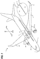
- FIG. 1 is a top isometric view of an aircraft 1 having a wing assembly 2 attached to an aircraft body 3 in accordance with an embodiment presented herein.
- the aircraft body 3 includes a right aircraft body member 3R and a corresponding left aircraft body member 3L.
- the wing assembly 2 includes a right wing assembly member 2R extending outwardly from the right aircraft body member 3R, and a left wing assembly member 2L extending outwardly from the left aircraft body member 3L.
- the wing assembly 2 further includes a wing box 10 extending through at least a member of the aircraft body 3.
- the wing box 10 structurally attaches the right wing assembly member 2R to the left wing assembly member 2L.
- Wing assembly members 2R and 2L are joined to the aircraft body members 3R and 3L, respectively, at an adjoining intersection 5, where an outer wing skin 6 of the wing assembly 2 intersects an outer body skin 7 of the aircraft body 3.
- the wing box 10 may be completely located within the wing assembly 2 and may further define an interior cavity structure, (not shown), that may include a fuel cell or any other cavity that may be separate compartmentalized and independent from the aircraft body 3.
- the interior cavity structure defined by the wing box 10 may be pressure tested independently from body 3 pressure testing. This allows testing for any pressure leakage before any aircraft body structure 3 is attached to the wing assembly 2.
- the wing box further includes a forward and rearward facing surfaces that are disposed in vertical direction
- the embodiments presented herein are novel methods and systems for adjoining the aircraft body 3 to the wing assembly 2 via the wing box 10 by means of attachment members 20 disposed on forward and rearward lateral edges of the wing box 10, proximate where the outer body skin 7 meets the outer wing skin 6.
- the aircraft 1 is a commercial aircraft having a first engine 4R carried by the right wing assembly member 2R, and a second engine 4L carried by the left wing assembly member 2L.
- the methods and systems described herein for attaching wings to bodies can be used on other aircraft, includes other commercial and non-commercial aircraft.
- other transport aircraft having one or more engines mounted to the aircraft body.
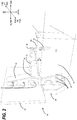
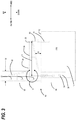
- FIG. 2 is a partially cutaway isometric view and FIG. 3 is a forward or rearward cutaway view illustrating a first embodiment of a one-piece attachment member 30 joined to a partially illustrated corner section of a wing box 10 and a fuselage structure 50.
- Wing box 10 is partially illustrated to identify an upper surface 12 of the wing box 10 and either a forward facing or rearward facing outer vertical surface 14 of the wing box 10. This orientation is based on whether the one-piece attachment member 30 is disposed on either the forward facing section of the wing box 10, or on the rearward facing section of the wing box 10, as both are illustrated in FIG.1 .
- the one-piece attachment member 30 is additionally located on the outboard member of the wing box 10 to enable fixed attachment to the aircraft body 3 via a fuselage member 50 that may including both a fuselage skin 52 and a trapezoid panel 54. A vertical load on the fuselage member 50 may be reduced when used in conjunction with the trapezoid panel 54.
- the fuselage skin 52 may also encompass the outboard member of the trapezoid panel 54, (not illustrated).
- the one-piece attachment member 30 includes an upper extension (upwardly extending projection) 32 that is fixedly connected via fasteners 33 to the fuselage member 50, particularly to the fuselage skin 52, and an inboard extension 34 having a distal end 36 opposite the fuselage member 50 being connected via an extension link (attachment link member) 60 to a vertical member 14 of the wing box 10 via a wing box fitting 70. Additionally, the one-piece attachment member 30 includes a lower extension (downwardly extending member) 38 that is fixedly connected via fasteners 39 to the vertical member 14 of the wing box 10, and either the trapezoid member 54 or directly to an outboard member of the fuselage skin 52, (not illustrated).
- the inboard extension 34 is oriented a distance D above a plane defined by the upper surface 12 of the wing box 10.
- a bending moment M increases the resistance or stiffness to any bending moment from any transient or static loading due to the distal end 36 of the inboard extension 34 having a substantial longitudinal separation from the attachment planes of the upper 32 and lower 38 extensions (upwardly and downwardly extending members) connected to their respective fuselage 52 and wing box 10/ trapezoid member 54 fastening locations.
- the inboard distance X of the distal end 36 of the inboard extension 34 to the centerline of bending moment M is greater than the width W, (see FIG. 3 ), of the upper 32 and lower 38 extension (upwardly and downwardly extending member) to accomplish this stiffening feature.
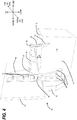
- FIG. 4 is a partially cutaway isometric view and FIG. 5 is a forward or rearward cutaway view illustrating a second embodiment of a two-piece attachment member 40 joined to a partially illustrated corner section of a wing box 10 and a fuselage structure 50. Similar elements between the various embodiments presented herein will be identified with similar reference numbers.
- Wing box 10 is partially illustrated to identify an upper surface 12 of the wing box 10 and either a forward or rearward vertical surface 14 of the wing box 10.
- the two-piece attachment member 40 is similarly located on the outboard member of the wing box 10 to enable fixed attachment to the aircraft body 3 via a fuselage member 50 that may including a fuselage skin 52.
- the inboard extension 44 is oriented a distance D above a plane defined by the upper surface 12 of the wing box 10.
- a bending moment M increases the resistance or stiffness to any bending moment from any transient or static loading due to the distal end 46 of the inboard extension 44 having a substantial longitudinal separation from the attachment planes of the upper 42 and lower 48 extensions connected to each other and to their respective fuselage 52 and wing box 10/trapezoid member 54 fastening locations.
- the inboard distance X of the distal end 46 of the inboard extension 44 to the centerline of the bending moment M is greater than the width W, (see FIG. 5 ), of the upper 42 and lower 48 extension to accomplish this stiffening feature.
- Fig. 6 illustrates an exploded isometric view of the second embodiment of the two-piece attachment member of FIGS. 4-5 in a method of being joined to a wing box 10 and a fuselage member 50.
- the method attaches the upper extension 42/inboard extension 44 members to the fuselage member 50, particularly the fuselage skin 52, via fasteners 43.
- Attachment link member 60 may be attached to the distal end 46 of the inboard extension 44 at this time, or may be attached to the wing box fitting 70, (not shown), in the alternative.
- the method attaches the lower extension 48 to the wing trapezoid member 54, and the vertical member 14 of the wing box 10 via fasteners 49.
- any internal cavity in the wing box 10 may be pressure tested to determine its structural integrity.
- the first assembly including the upper extension 42/inboard extension 44 members and the attached fuselage member 50 are then positioned into alignment with the corresponding second assembly including the lower extension 48 and wing box 10.
- the first and second assembly are then brought into contact at a connecting bottom member of the upper extension 42 and a connecting top member of the lower extension 48 and fixedly connected with fasteners 41.
- the attachment link member 60 then may be connected between the distal end 46 of the inboard extension 44 and the wing box fitting 70 mounted on the wing box 10.
- any secondary fuel barrier application process on any external parts of a fuel cell located within the wing box 10 common to the body pressure boundary may be completed in a controlled environment prior to the wing assembly 2 is joined to the aircraft body 3 and will not be penetrated during the wing to body joining.
- the wing assembly 2 carries the majority of the forces through the fuselage 50 to the aircraft body 3 via the attachment members (30 or 40) and the attachment link member 60 attachment wing box fitting 70.
- a first loading condition is present when the aircraft 1 is on the ground, having no lift component on the wing assembly 2, where the attachment members (30 or 40) bear the weight of the aircraft body 3 and transfer it through the wing assembly 2 to main landing gears (not illustrated).
- a second loading condition is present where the attachment members (30 or 40) transfer a lift load induced by the in-flight wing assembly 2 to the aircraft body 3 via the attachment members (30 or 40) and the attachment link member 60 attachment wing box fitting 70.
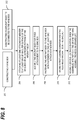
- FIG. 7 is a logical flowchart process illustrating a method of attaching a wing assembly to an aircraft body as shown in Fig. 6 .
- the method starts with constructing 100 a wing box 10, and constructing 102 the aircraft body 3 to be connected to the wing box 10.
- An attachment member 30, 40 is attached 104 to either an outer surface 14 of the wing box 10 or an outboard member 52 of the fuselage member 50.
- the attachment member may include a one-piece design 30 that is attached to either the wing box 10 or the fuselage member 50, or may include a two-piece design 40 where each respective piece connects to the wing box 10 and the fuselage member 50 and is later joined together.
- the fuselage member 50 is aligned 106 with the wing box 10 such that the attachment member is either connected to the respective surface of the opposing fuselage member 50 or wing box 10 in the one-piece design 30, or in the two-piece design 40, the upper 42 and lower 48 attachment members are connected together. Additionally, in either the one-piece or two-piece configuration, the attachment link member 60 on the inboard extension is aligned with the wing box fitting 70. Finally, the fuselage member 50 is fastened 108 to the wing box 10 with a plurality of fasteners such that the attachment member fixedly holds the fuselage member 50 to the wing box 10.
- FIG. 8 is a logical flowchart process illustrating a method of loading an aircraft body in a grounded position and an airborne position. Similar to the method described in FIG. 7 , a wing box 10 is constructed 200, and an aircraft body 3 is constructed 202 to be connected to the wing box 10. An attachment member 30, 40 is attached 204 to either an outer surface 14 of the wing box 10 or an outboard member 52of the fuselage member 50. As mentioned above, the attachment member may include a one-piece design 30 that is attached to either the wing box 10 or the fuselage member 50, or may include a two-piece design 40 where each respective piece connects to the wing box 10 and the fuselage member 50 and is later joined together.
- the fuselage member 50 is aligned 206 with the wing box 10 such that the attachment member is either connected to the respective surface of the opposing fuselage member 50 or wing box 10 in the one-piece design 30, or in the two-piece design 40, the upper 42 and lower 48 attachment members are connected together via fasteners 41. Additionally, in either the one-piece or two-piece configuration, the attachment link member 60 on the inboard extension is aligned with wing box fitting 70.
- the fuselage member 50 is fastened 208 to the wing box 10 with a plurality of fasteners such that the attachment member fixedly holds the fuselage member 50 to the wing box 10.
- the method further includes a first loading condition 210 when the aircraft 1 is on the ground, with no lift component on the wing assembly 2, where the attachment members 30, 40 bear the weight of the aircraft body 3 and transfer it through the wing assembly 2 and wing box 10 to main landing gears (not shown).
- a second loading condition 212 is present where the attachment members (30, 40) transfer a lift load induced by the in-flight wing assembly 2 to the aircraft body 3 and fuselage member 50 from the wing assembly 2 through the wing box 10.
- Aircraft body support members 30, 40 may be fully installed to either the fuselage 50 or the wing box 10 in one-piece embodiment, or separately installed in a two-piece embodiment on the fuselage 50 and the wing box 10 for subsequent attachment.
- the embodiments disclosed herein allow the aircraft body frame 3 connection to the forward or rearward vertical surface 14 of the wing box 10 to be de-coupled from a common interface of a wing assembly 3 with the wing fuel cell in the wing box 10 by only attaching the aircraft body frame attachment members 30, 40 to the wing assembly 2 wing box 10 through vertical attachment interfaces 32, 38 and 42, 48 outside the wing box 10.
- This configuration allows the wing box 10 to be completed prior to joining to the aircraft body 3. It also allows the aircraft body frames to be fully installed to the aircraft body skin 52 in one piece prior to joining to the wing 2, thereby reducing weight and eliminating frame splicing of multiple frame parts. This configuration results in a weight savings and less manufacturing work at the wing to body join position by significantly reducing the difficult installation of body frame stub beams to the wing box.
Claims (12)
- Aéroplane (1) comprenant un corps d'aéroplane (3) ayant une pluralité d'éléments de châssis de corps d'un élément hors-bord du corps d'aéroplane (3), un caisson d'aile (10) s'étendant à travers un élément du corps d'aéroplane (3) et un dispositif de fixation comprenant :au moins une paire d'un élément de fixation en une pièce (30) et d'un élément de liaison de fixation (60) fixée fermement à une surface externe du caisson d'aile (10) ou, en variante, une paire d'un élément de fixation en deux pièces (40) et d'un élément de liaison de fixation (60) fixée fermement à une surface externe du caisson d'aile (10),caractérisé en ce que l'élément de fixation comprend :une saillie s'étendant vers le haut (32, 42) qui reçoit l'élément hors-bord du corps d'aéroplane (3),un élément s'étendant vers le bas (38, 48) qui reçoit l'élément hors-bord du corps d'aéroplane (3) et la surface externe du caisson d'aile (10), dans lequel, pour l'élément de fixation en deux pièces, en variante, la saillie s'étendant vers le haut (32, 42) et l'élément s'étendant vers le bas (38, 48) sont fixés fermement etune saillie s'étendant à bord (34, 44) qui reçoit l'élément de liaison de fixation (60) en étant connecté à une surface externe à bord du caisson d'aile (10) via l'élément de liaison de fixation (60) ; etune pluralité de dispositifs de fixation (39, 49) fixant fermement le corps d'aéroplane (3) à l'élément de fixation (30, 40) et à l'élément de liaison de fixation (60), fixant ainsi le corps d'aéroplane (3) au caisson d'aile (10),la saillie s'étendant à bord (34, 44) couplant la saillie s'étendant vers le haut (32) à l'élément de liaison de fixation (60).
- Aéroplane (1) selon la revendication 1, dans lequel l'élément de fixation (30) est fixé à une surface verticale externe du caisson d'aile (10) par la pluralité de dispositifs de fixation (39, 49).
- Aéroplane (1) selon la revendication 2, dans lequel la surface verticale externe du caisson d'aile (10) comprend en outre un élément parmi :une surface avant du caisson d'aile ; ouune surface arrière du caisson d'aile.
- Aéroplane (1) selon l'une des revendications précédentes, dans lequel la pluralité de dispositifs de fixation (39, 49) sont disposés à l'extérieur d'une cavité intérieure du caisson d'aile (10).
- Aéroplane (1) selon l'une des revendications précédentes, comprenant en outre :
une pile à combustible d'aile disposée sur une cavité intérieure du caisson d'aile (10). - Aéroplane (1) selon la revendication 6, la pluralité de dispositifs de fixation qui fixent fermement le corps d'aéroplane au caisson d'aile se trouvant à l'extérieur de la pile à combustible d'aile.
- Procédé d'assemblage d'un aéroplane (1), ce procédé comprenant :la construction d'un caisson d'aile (10) ;la construction d'un corps d'aéroplane (3) à connecter au caisson d'aile (10) ;la fixation d'au moins une paire d'un élément de fixation en une pièce (30) et d'un élément de liaison de fixation (60) à au moins un élément parmi une surface externe du caisson d'aile (10) ou un élément hors-bord du corps d'aéroplane (3) ou, en variante, une paire d'un élément de fixation en deux pièces (40) et d'un élément de liaison de fixation (60) à au moins un élément parmi une surface externe du caisson d'aile (10) ou un élément hors-bord du corps d'aéroplane (3) ;l'alignement du corps d'aéroplane (3) pour la fixation ferme au caisson d'aile (10) ; etla fixation du corps d'aéroplane (3) au caisson d'aile (10) avec des dispositifs de fixation (39, 49) via l'au moins un élément de fixation en une pièce ou en deux pièces (30, 40),caractérisé en ce que l'élément de fixation (30, 40) comprend :une saillie s'étendant vers le haut (32, 42) qui reçoit l'élément hors-bord du corps d'aéroplane (3),un élément s'étendant vers le bas (38, 48) qui reçoit l'élément hors-bord du corps d'aéroplane (3) et la surface externe du caisson d'aile (10), dans lequel, pour l'élément de fixation en deux pièces, en variante, la saillie s'étendant vers le haut (32, 42) et l'élément s'étendant vers le bas (38, 48) sont fixés fermement etune saillie s'étendant à bord (34, 44) qui reçoit un élément de liaison de fixation (60) en étant connecté à une surface externe à bord du caisson d'aile (10) via l'élément de liaison de fixation (60) ; etune pluralité de dispositifs de fixation (39, 49) fixant fermement le corps d'aéroplane (3) à l'élément de fixation (30, 40) et à l'élément de liaison de fixation (60), fixant ainsi le corps d'aéroplane (3) au caisson d'aile (10),la saillie s'étendant à bord (34, 44) couplant la saillie s'étendant vers le haut (32) à l'élément de liaison de fixation (60).
- Procédé selon la revendication 7, comprenant en outre :
le test en pression d'une cavité interne dans le caisson d'aile (10) après la fixation de l'au moins un élément de fixation (30, 40) à la surface externe du caisson d'aile (10) et avant la fixation du corps d'aéroplane (3) au caisson d'aile (10). - Procédé selon l'une des revendications 7 à 8, comprenant en outre :
la fixation de l'élément de liaison de fixation (60) de l'au moins un élément de fixation (30, 40) à la surface externe du caisson d'aile (10) à une certaine distance de l'élément hors-bord du corps d'aéroplane (3). - Procédé selon l'une des revendications 7 à 9, dans lequel la fixation d'au moins un élément de fixation (30, 40) comprend en outre :
la fixation d'au moins un élément de fixation (30, 40) à un élément parmi une surface avant ou une surface arrière d'une surface verticale externe du caisson d'aile (10). - Procédé selon l'une des revendications 7 à 10, dans lequel la fixation du corps d'aéroplane (3) au caisson d'aile (10) comprend en outre :
la prévention de l'entrée des dispositifs de fixation (39, 49) dans une cavité intérieure du caisson d'aile (10) pendant la fixation. - Procédé selon l'une des revendications 7 à 11, dans lequel l'au moins un élément de fixation (30, 40) comprend une extension supérieure et une extension inférieure, la fixation d'au moins un élément de fixation comprenant en outre :la fixation de l'extension supérieure à l'élément hors bord du corps d'aéroplane (3) ;la fixation de l'extension inférieure à la surface externe du caisson d'aile (10) ;la fixation du corps d'aéroplane (3) au caisson d'aile (10) comprenant en outre la fixation du corps d'aéroplane (3) au caisson d'aile (10) avec des dispositifs de fixation (39, 49) via l'extension supérieure et l'extension inférieure de l'au moins un élément de fixation (30, 40).
Applications Claiming Priority (2)
| Application Number | Priority Date | Filing Date | Title |
|---|---|---|---|
| US13/652,975 US8857765B2 (en) | 2012-10-16 | 2012-10-16 | Method and apparatus for attaching an aircraft fuselage frame to a wing box |
| PCT/US2013/063913 WO2014062423A1 (fr) | 2012-10-16 | 2013-10-08 | Procédé et appareil pour fixer un cadre de fuselage d'aéronef à un caisson de voilure |
Publications (2)
| Publication Number | Publication Date |
|---|---|
| EP2909085A1 EP2909085A1 (fr) | 2015-08-26 |
| EP2909085B1 true EP2909085B1 (fr) | 2018-08-29 |
Family
ID=49385426
Family Applications (1)
| Application Number | Title | Priority Date | Filing Date |
|---|---|---|---|
| EP13779498.8A Active EP2909085B1 (fr) | 2012-10-16 | 2013-10-08 | Procédé et appareil pour fixer un cadre de fuselage d'aéronef à un caisson de voilure |
Country Status (5)
| Country | Link |
|---|---|
| US (1) | US8857765B2 (fr) |
| EP (1) | EP2909085B1 (fr) |
| JP (1) | JP6159409B2 (fr) |
| CN (1) | CN104603007B (fr) |
| WO (1) | WO2014062423A1 (fr) |
Families Citing this family (10)
| Publication number | Priority date | Publication date | Assignee | Title |
|---|---|---|---|---|
| FR2998868B1 (fr) * | 2012-11-30 | 2016-02-05 | Airbus Operations Sas | Dispositif de fixation intermediaire entre un fuselage d'aeronef et un train d'atterrissage d'aeronef |
| US9828083B2 (en) | 2014-11-14 | 2017-11-28 | The Boeing Company | Methods and components for wing-to-fuselage integration |
| US10106240B2 (en) | 2015-07-13 | 2018-10-23 | The Boeing Company | Pinned fuselage-to-wing connection |
| US10275565B2 (en) | 2015-11-06 | 2019-04-30 | The Boeing Company | Advanced automated process for the wing-to-body join of an aircraft with predictive surface scanning |
| DE102017117314A1 (de) * | 2017-07-31 | 2019-01-31 | Airbus Operations Gmbh | Befestigungseinheit zum beweglichen Befestigen einer Luftfahrzeugkomponente an einer Tragstruktur eines Luftfahrzeugs |
| US10712730B2 (en) | 2018-10-04 | 2020-07-14 | The Boeing Company | Methods of synchronizing manufacturing of a shimless assembly |
| US11136107B2 (en) * | 2018-10-05 | 2021-10-05 | The Boeing Company | Method and apparatus for attaching a fuselage frame to a wing box |
| US11174042B2 (en) | 2018-10-09 | 2021-11-16 | The Boeing Company | Wing join system and method for a wing assembly |
| CN109774964A (zh) * | 2019-01-28 | 2019-05-21 | 陕西智翔航空科技发展有限公司 | 复合材料机身对合型架 |
| BR102021017320A2 (pt) * | 2020-11-03 | 2022-07-26 | The Boeing Company | Sistema e método para prender uma porção de uma fuselagem de uma aeronave a uma porção de uma asa da aeronave |
Family Cites Families (47)
| Publication number | Priority date | Publication date | Assignee | Title |
|---|---|---|---|---|
| US1865964A (en) | 1926-09-27 | 1932-07-05 | Rohrbach Patents Corp | Monoplane |
| US2001260A (en) | 1932-07-20 | 1935-05-14 | Martin James | Construction and arrangement of aeroplane wings |
| US2211089A (en) * | 1938-03-29 | 1940-08-13 | Curtiss Wright Corp | Wing and fuselage construction |
| US2370801A (en) | 1941-05-14 | 1945-03-06 | Cons Vultee Aireraft Corp | Airplane wing structure |
| US2412778A (en) | 1944-12-18 | 1946-12-17 | Cons Vultee Aircraft Corp | Suspension type flooring for aircraft |
| US2779558A (en) | 1952-04-09 | 1957-01-29 | Sncase | Fuselage of aerodynes |
| US2749061A (en) | 1954-06-18 | 1956-06-05 | Wesley A Franz | Airplane wing stress compensating structure assembly |
| US3018985A (en) | 1956-12-31 | 1962-01-30 | Martin Marietta Corp | Swept wing with unswept spar |
| US3942746A (en) * | 1971-12-27 | 1976-03-09 | General Dynamics Corporation | Aircraft having improved performance with beaver-tail afterbody configuration |
| US4120998A (en) * | 1977-02-03 | 1978-10-17 | Northrop Corporation | Composite structure |
| DE2932667C2 (de) | 1979-08-11 | 1982-07-29 | Messerschmitt-Bölkow-Blohm GmbH, 8000 München | Hauptanschluß für den Tragflügel eines Luftfahrzeuges |
| US4417708A (en) | 1982-05-12 | 1983-11-29 | Grumman Aerospace Corporation | Interchangeable wing aircraft |
| US4893964A (en) * | 1989-02-06 | 1990-01-16 | Grumman Aerospace Corporation | Interlocking structural members utilizing overlying composite strips |
| US5332178A (en) * | 1992-06-05 | 1994-07-26 | Williams International Corporation | Composite wing and manufacturing process thereof |
| EP0888202B1 (fr) * | 1996-03-22 | 2005-08-10 | The Boeing Company | Montage determinant de voilures |
| CA2444560C (fr) * | 2002-10-21 | 2008-09-23 | The Boeing Company | Methode et dispositif de soutien rotatif d'elements mobiles, y compris de plans canard |
| FR2873347B1 (fr) * | 2004-07-22 | 2006-11-17 | Airbus France Sas | Dispositif d'eclissage d'elements de structure composite avec des elements de structure metallique |
| FR2883548B1 (fr) * | 2005-03-23 | 2007-06-15 | Airbus France Sas | Dispositif et procede d'eclissage mixte carbone-metal dissymetrique |
| DE102005034891B4 (de) * | 2005-07-26 | 2007-06-14 | Airbus Deutschland Gmbh | Querkraftanschluss |
| US8142126B2 (en) * | 2005-09-02 | 2012-03-27 | The Boeing Company | Multi-piece fastener with self-indexing nut |
| US9359061B2 (en) * | 2005-10-31 | 2016-06-07 | The Boeing Company | Compliant stiffener for aircraft fuselage |
| US7398586B2 (en) * | 2005-11-01 | 2008-07-15 | The Boeing Company | Methods and systems for manufacturing a family of aircraft wings and other composite structures |
| GB0525896D0 (en) * | 2005-12-20 | 2006-02-01 | Airbus Uk Ltd | A joint for use in aircraft construction |
| US7501814B2 (en) * | 2006-09-07 | 2009-03-10 | Southwest Research Institute | Apparatus and method for second-layer through-bushing inspection of aircraft wing attachment fittings using electric current perturbation |
| US7546979B1 (en) | 2006-09-15 | 2009-06-16 | The Boeing Company | Trapezoidal panel pin joint allowing free deflection between fuselage and wing |
| DE102006051572B4 (de) * | 2006-11-02 | 2010-01-21 | Airbus Deutschland Gmbh | Flügel-Rumpf-Verbindung eines Flugzeugs |
| US7721992B2 (en) * | 2007-03-07 | 2010-05-25 | The Boeing Company | Aircraft floor to fuselage attachment |
| FR2913400B1 (fr) * | 2007-03-07 | 2009-11-20 | Airbus France | Plancher d'aeronef et fuselage muni d'un tel plancher. |
| US8016236B2 (en) * | 2007-04-04 | 2011-09-13 | The Boeing Company | Method and apparatus for attaching a wing to a body |
| FR2915173B1 (fr) * | 2007-04-17 | 2009-10-23 | Airbus Sa Sa | Dispositif de fixation d'un organe de sustentation au fuselage d'un avion. |
| US7887009B2 (en) * | 2007-12-05 | 2011-02-15 | The Boeing Company | Methods and systems for attaching aircraft wings to fuselages |
| GB0803692D0 (en) * | 2008-02-29 | 2008-04-09 | Airbus Uk Ltd | Fitting for pivotally connecting aerodynamic control element to aircraft structure |
| US7975965B2 (en) * | 2008-05-13 | 2011-07-12 | The Boeing Company | Wing tip joint in airfoils |
| CN100577512C (zh) * | 2008-06-24 | 2010-01-06 | 北京航空航天大学 | 一种民用大型飞机机翼机身连接接头 |
| GB0901228D0 (en) | 2009-01-26 | 2009-03-11 | Airbus Uk Ltd | Aircraft joint |
| US8061655B1 (en) * | 2009-03-25 | 2011-11-22 | The Boeing Company | Aircraft configuration utilizing fuselage, wing, empennage, and exhaust flow control devices |
| ES2378702B1 (es) * | 2009-04-21 | 2013-02-28 | Airbus Operations, S.L. | Herrajes para la cogida del estabilizador vertical de cola de una aeronave. |
| FR2948099B1 (fr) * | 2009-07-16 | 2012-05-11 | Airbus Operations Sas | Procede de fabrication d'un aeronef a voilure fixe |
| ES2372849B1 (es) * | 2010-03-25 | 2012-12-13 | Airbus Operations, S.L. | Estructura de unión de cajones de torsión en una aeronave mediante un herraje triforme de materiales compuestos no metálicos. |
| DE102010013370B8 (de) * | 2010-03-30 | 2013-12-12 | Eads Deutschland Gmbh | Wandbauteil für ein Luftfahrzeug |
| GB201009922D0 (en) * | 2010-06-14 | 2010-07-21 | Airbus Uk Ltd | Aircraft wing box joint |
| US8333345B2 (en) * | 2010-08-26 | 2012-12-18 | The Boeing Company | Composite aircraft joint |
| FR2970463B1 (fr) | 2011-01-17 | 2013-02-15 | Airbus Operations Sas | Dispositif d'eclissage a tenue mecanique amelioree. |
| FR2970942B1 (fr) * | 2011-01-28 | 2013-02-22 | Airbus Operations Sas | Raccordement des cadres de raidissage entre un fuselage d'aeronef et un caisson de voilure |
| US8777158B2 (en) * | 2011-03-25 | 2014-07-15 | The Boeing Company | Joint sealing system |
| FR2972997B1 (fr) * | 2011-03-25 | 2013-05-10 | Airbus Operations Sas | Raccordement d'un fuselage a une voilure d'aeronef |
| US9878772B2 (en) * | 2012-01-10 | 2018-01-30 | Gulfstream Aerospace Corporation | Mounting assembly and method for mounting a sound-deadening body to a fuselage of an aircraft |
-
2012
- 2012-10-16 US US13/652,975 patent/US8857765B2/en active Active
-
2013
- 2013-10-08 CN CN201380044940.4A patent/CN104603007B/zh active Active
- 2013-10-08 WO PCT/US2013/063913 patent/WO2014062423A1/fr active Application Filing
- 2013-10-08 EP EP13779498.8A patent/EP2909085B1/fr active Active
- 2013-10-08 JP JP2015536842A patent/JP6159409B2/ja active Active
Also Published As
| Publication number | Publication date |
|---|---|
| JP6159409B2 (ja) | 2017-07-05 |
| CN104603007B (zh) | 2016-08-10 |
| US20140103162A1 (en) | 2014-04-17 |
| EP2909085A1 (fr) | 2015-08-26 |
| US8857765B2 (en) | 2014-10-14 |
| CN104603007A (zh) | 2015-05-06 |
| WO2014062423A1 (fr) | 2014-04-24 |
| JP2015533111A (ja) | 2015-11-19 |
Similar Documents
| Publication | Publication Date | Title |
|---|---|---|
| EP2909085B1 (fr) | Procédé et appareil pour fixer un cadre de fuselage d'aéronef à un caisson de voilure | |
| US7887009B2 (en) | Methods and systems for attaching aircraft wings to fuselages | |
| KR102073995B1 (ko) | 항공기의 복합재료 구조를 연결하기 위한 장치 및 방법 | |
| US8186622B2 (en) | Aircraft component | |
| US8740151B1 (en) | Adjustable splice fitting for shimless connection of structual members | |
| CN102239086B (zh) | 贴在机身的侧向延伸部上以将其固定的飞行器吊架刚性结构 | |
| EP3632790B1 (fr) | Procédé et appareil de fixation d'un cadre de fuselage sur un caisson de voilure | |
| US9180956B1 (en) | Methods and apparatus for attaching an aircraft wing assembly to an aircraft body | |
| KR101950645B1 (ko) | 조인트 조립체와 그 조립방법 | |
| US20200189714A1 (en) | Aircraft wing-to-fuselage interface permitting positional adjustment | |
| US20230046394A1 (en) | Structural arrangement for strut-braced wing assembly of an aircraft | |
| EP2626291B1 (fr) | Joint structurel comprenant une peau en continu avec des lisees d'attache montées aux surfaces intérieure et extérieure | |
| US20160152315A1 (en) | Aircraft fuselage frame | |
| US20170066518A1 (en) | Aircraft rear portion comprising a vertical stabilizer having a box-section structure including a lower portion accommodated in the fuselage | |
| EP3619110B1 (fr) | Unité d'aile d'avion avec clôture à pression | |
| EP3619109B1 (fr) | Unité d'aile d'aéronef à peau de voilure supérieure délimitant un plancher étanche | |
| US9764815B2 (en) | Aircraft fuselage structure | |
| US20160325820A1 (en) | Structural component | |
| CN115107986B (zh) | 一种翼身连接机身加强框结构 | |
| CN219927958U (zh) | 一种大载荷轻质隐身的复合材料机身结构 |
Legal Events
| Date | Code | Title | Description |
|---|---|---|---|
| PUAI | Public reference made under article 153(3) epc to a published international application that has entered the european phase |
Free format text: ORIGINAL CODE: 0009012 |
|
| 17P | Request for examination filed |
Effective date: 20150427 |
|
| AK | Designated contracting states |
Kind code of ref document: A1 Designated state(s): AL AT BE BG CH CY CZ DE DK EE ES FI FR GB GR HR HU IE IS IT LI LT LU LV MC MK MT NL NO PL PT RO RS SE SI SK SM TR |
|
| AX | Request for extension of the european patent |
Extension state: BA ME |
|
| DAX | Request for extension of the european patent (deleted) | ||
| 17Q | First examination report despatched |
Effective date: 20170221 |
|
| GRAP | Despatch of communication of intention to grant a patent |
Free format text: ORIGINAL CODE: EPIDOSNIGR1 |
|
| INTG | Intention to grant announced |
Effective date: 20180309 |
|
| GRAS | Grant fee paid |
Free format text: ORIGINAL CODE: EPIDOSNIGR3 |
|
| GRAA | (expected) grant |
Free format text: ORIGINAL CODE: 0009210 |
|
| AK | Designated contracting states |
Kind code of ref document: B1 Designated state(s): AL AT BE BG CH CY CZ DE DK EE ES FI FR GB GR HR HU IE IS IT LI LT LU LV MC MK MT NL NO PL PT RO RS SE SI SK SM TR |
|
| REG | Reference to a national code |
Ref country code: GB Ref legal event code: FG4D |
|
| REG | Reference to a national code |
Ref country code: CH Ref legal event code: EP |
|
| REG | Reference to a national code |
Ref country code: AT Ref legal event code: REF Ref document number: 1034809 Country of ref document: AT Kind code of ref document: T Effective date: 20180915 |
|
| REG | Reference to a national code |
Ref country code: IE Ref legal event code: FG4D |
|
| REG | Reference to a national code |
Ref country code: DE Ref legal event code: R096 Ref document number: 602013042804 Country of ref document: DE |
|
| REG | Reference to a national code |
Ref country code: FR Ref legal event code: PLFP Year of fee payment: 6 |
|
| REG | Reference to a national code |
Ref country code: NL Ref legal event code: MP Effective date: 20180829 |
|
| REG | Reference to a national code |
Ref country code: LT Ref legal event code: MG4D |
|
| PG25 | Lapsed in a contracting state [announced via postgrant information from national office to epo] |
Ref country code: FI Free format text: LAPSE BECAUSE OF FAILURE TO SUBMIT A TRANSLATION OF THE DESCRIPTION OR TO PAY THE FEE WITHIN THE PRESCRIBED TIME-LIMIT Effective date: 20180829 Ref country code: GR Free format text: LAPSE BECAUSE OF FAILURE TO SUBMIT A TRANSLATION OF THE DESCRIPTION OR TO PAY THE FEE WITHIN THE PRESCRIBED TIME-LIMIT Effective date: 20181130 Ref country code: IS Free format text: LAPSE BECAUSE OF FAILURE TO SUBMIT A TRANSLATION OF THE DESCRIPTION OR TO PAY THE FEE WITHIN THE PRESCRIBED TIME-LIMIT Effective date: 20181229 Ref country code: LT Free format text: LAPSE BECAUSE OF FAILURE TO SUBMIT A TRANSLATION OF THE DESCRIPTION OR TO PAY THE FEE WITHIN THE PRESCRIBED TIME-LIMIT Effective date: 20180829 Ref country code: NL Free format text: LAPSE BECAUSE OF FAILURE TO SUBMIT A TRANSLATION OF THE DESCRIPTION OR TO PAY THE FEE WITHIN THE PRESCRIBED TIME-LIMIT Effective date: 20180829 Ref country code: BG Free format text: LAPSE BECAUSE OF FAILURE TO SUBMIT A TRANSLATION OF THE DESCRIPTION OR TO PAY THE FEE WITHIN THE PRESCRIBED TIME-LIMIT Effective date: 20181129 Ref country code: NO Free format text: LAPSE BECAUSE OF FAILURE TO SUBMIT A TRANSLATION OF THE DESCRIPTION OR TO PAY THE FEE WITHIN THE PRESCRIBED TIME-LIMIT Effective date: 20181129 Ref country code: RS Free format text: LAPSE BECAUSE OF FAILURE TO SUBMIT A TRANSLATION OF THE DESCRIPTION OR TO PAY THE FEE WITHIN THE PRESCRIBED TIME-LIMIT Effective date: 20180829 Ref country code: SE Free format text: LAPSE BECAUSE OF FAILURE TO SUBMIT A TRANSLATION OF THE DESCRIPTION OR TO PAY THE FEE WITHIN THE PRESCRIBED TIME-LIMIT Effective date: 20180829 |
|
| REG | Reference to a national code |
Ref country code: AT Ref legal event code: MK05 Ref document number: 1034809 Country of ref document: AT Kind code of ref document: T Effective date: 20180829 |
|
| PG25 | Lapsed in a contracting state [announced via postgrant information from national office to epo] |
Ref country code: LV Free format text: LAPSE BECAUSE OF FAILURE TO SUBMIT A TRANSLATION OF THE DESCRIPTION OR TO PAY THE FEE WITHIN THE PRESCRIBED TIME-LIMIT Effective date: 20180829 Ref country code: AL Free format text: LAPSE BECAUSE OF FAILURE TO SUBMIT A TRANSLATION OF THE DESCRIPTION OR TO PAY THE FEE WITHIN THE PRESCRIBED TIME-LIMIT Effective date: 20180829 Ref country code: HR Free format text: LAPSE BECAUSE OF FAILURE TO SUBMIT A TRANSLATION OF THE DESCRIPTION OR TO PAY THE FEE WITHIN THE PRESCRIBED TIME-LIMIT Effective date: 20180829 |
|
| PG25 | Lapsed in a contracting state [announced via postgrant information from national office to epo] |
Ref country code: ES Free format text: LAPSE BECAUSE OF FAILURE TO SUBMIT A TRANSLATION OF THE DESCRIPTION OR TO PAY THE FEE WITHIN THE PRESCRIBED TIME-LIMIT Effective date: 20180829 Ref country code: EE Free format text: LAPSE BECAUSE OF FAILURE TO SUBMIT A TRANSLATION OF THE DESCRIPTION OR TO PAY THE FEE WITHIN THE PRESCRIBED TIME-LIMIT Effective date: 20180829 Ref country code: PL Free format text: LAPSE BECAUSE OF FAILURE TO SUBMIT A TRANSLATION OF THE DESCRIPTION OR TO PAY THE FEE WITHIN THE PRESCRIBED TIME-LIMIT Effective date: 20180829 Ref country code: IT Free format text: LAPSE BECAUSE OF FAILURE TO SUBMIT A TRANSLATION OF THE DESCRIPTION OR TO PAY THE FEE WITHIN THE PRESCRIBED TIME-LIMIT Effective date: 20180829 Ref country code: RO Free format text: LAPSE BECAUSE OF FAILURE TO SUBMIT A TRANSLATION OF THE DESCRIPTION OR TO PAY THE FEE WITHIN THE PRESCRIBED TIME-LIMIT Effective date: 20180829 Ref country code: AT Free format text: LAPSE BECAUSE OF FAILURE TO SUBMIT A TRANSLATION OF THE DESCRIPTION OR TO PAY THE FEE WITHIN THE PRESCRIBED TIME-LIMIT Effective date: 20180829 Ref country code: CZ Free format text: LAPSE BECAUSE OF FAILURE TO SUBMIT A TRANSLATION OF THE DESCRIPTION OR TO PAY THE FEE WITHIN THE PRESCRIBED TIME-LIMIT Effective date: 20180829 |
|
| PG25 | Lapsed in a contracting state [announced via postgrant information from national office to epo] |
Ref country code: DK Free format text: LAPSE BECAUSE OF FAILURE TO SUBMIT A TRANSLATION OF THE DESCRIPTION OR TO PAY THE FEE WITHIN THE PRESCRIBED TIME-LIMIT Effective date: 20180829 Ref country code: SM Free format text: LAPSE BECAUSE OF FAILURE TO SUBMIT A TRANSLATION OF THE DESCRIPTION OR TO PAY THE FEE WITHIN THE PRESCRIBED TIME-LIMIT Effective date: 20180829 Ref country code: SK Free format text: LAPSE BECAUSE OF FAILURE TO SUBMIT A TRANSLATION OF THE DESCRIPTION OR TO PAY THE FEE WITHIN THE PRESCRIBED TIME-LIMIT Effective date: 20180829 |
|
| REG | Reference to a national code |
Ref country code: CH Ref legal event code: PL Ref country code: DE Ref legal event code: R097 Ref document number: 602013042804 Country of ref document: DE |
|
| REG | Reference to a national code |
Ref country code: BE Ref legal event code: MM Effective date: 20181031 |
|
| PG25 | Lapsed in a contracting state [announced via postgrant information from national office to epo] |
Ref country code: MC Free format text: LAPSE BECAUSE OF FAILURE TO SUBMIT A TRANSLATION OF THE DESCRIPTION OR TO PAY THE FEE WITHIN THE PRESCRIBED TIME-LIMIT Effective date: 20180829 Ref country code: LU Free format text: LAPSE BECAUSE OF NON-PAYMENT OF DUE FEES Effective date: 20181008 |
|
| PLBE | No opposition filed within time limit |
Free format text: ORIGINAL CODE: 0009261 |
|
| STAA | Information on the status of an ep patent application or granted ep patent |
Free format text: STATUS: NO OPPOSITION FILED WITHIN TIME LIMIT |
|
| REG | Reference to a national code |
Ref country code: IE Ref legal event code: MM4A |
|
| 26N | No opposition filed |
Effective date: 20190531 |
|
| PG25 | Lapsed in a contracting state [announced via postgrant information from national office to epo] |
Ref country code: CH Free format text: LAPSE BECAUSE OF NON-PAYMENT OF DUE FEES Effective date: 20181031 Ref country code: SI Free format text: LAPSE BECAUSE OF FAILURE TO SUBMIT A TRANSLATION OF THE DESCRIPTION OR TO PAY THE FEE WITHIN THE PRESCRIBED TIME-LIMIT Effective date: 20180829 Ref country code: BE Free format text: LAPSE BECAUSE OF NON-PAYMENT OF DUE FEES Effective date: 20181031 Ref country code: LI Free format text: LAPSE BECAUSE OF NON-PAYMENT OF DUE FEES Effective date: 20181031 |
|
| PG25 | Lapsed in a contracting state [announced via postgrant information from national office to epo] |
Ref country code: IE Free format text: LAPSE BECAUSE OF NON-PAYMENT OF DUE FEES Effective date: 20181008 |
|
| REG | Reference to a national code |
Ref country code: DE Ref legal event code: R082 Ref document number: 602013042804 Country of ref document: DE Representative=s name: MAIER, LL.M., MICHAEL C., DE Ref country code: DE Ref legal event code: R082 Ref document number: 602013042804 Country of ref document: DE Representative=s name: BOULT WADE TENNANT LLP, DE |
|
| PG25 | Lapsed in a contracting state [announced via postgrant information from national office to epo] |
Ref country code: MT Free format text: LAPSE BECAUSE OF NON-PAYMENT OF DUE FEES Effective date: 20181008 |
|
| REG | Reference to a national code |
Ref country code: DE Ref legal event code: R082 Ref document number: 602013042804 Country of ref document: DE Representative=s name: BOULT WADE TENNANT LLP, DE |
|
| PG25 | Lapsed in a contracting state [announced via postgrant information from national office to epo] |
Ref country code: TR Free format text: LAPSE BECAUSE OF FAILURE TO SUBMIT A TRANSLATION OF THE DESCRIPTION OR TO PAY THE FEE WITHIN THE PRESCRIBED TIME-LIMIT Effective date: 20180829 |
|
| PG25 | Lapsed in a contracting state [announced via postgrant information from national office to epo] |
Ref country code: PT Free format text: LAPSE BECAUSE OF FAILURE TO SUBMIT A TRANSLATION OF THE DESCRIPTION OR TO PAY THE FEE WITHIN THE PRESCRIBED TIME-LIMIT Effective date: 20180829 |
|
| PG25 | Lapsed in a contracting state [announced via postgrant information from national office to epo] |
Ref country code: HU Free format text: LAPSE BECAUSE OF FAILURE TO SUBMIT A TRANSLATION OF THE DESCRIPTION OR TO PAY THE FEE WITHIN THE PRESCRIBED TIME-LIMIT; INVALID AB INITIO Effective date: 20131008 Ref country code: MK Free format text: LAPSE BECAUSE OF NON-PAYMENT OF DUE FEES Effective date: 20180829 Ref country code: CY Free format text: LAPSE BECAUSE OF FAILURE TO SUBMIT A TRANSLATION OF THE DESCRIPTION OR TO PAY THE FEE WITHIN THE PRESCRIBED TIME-LIMIT Effective date: 20180829 |
|
| P01 | Opt-out of the competence of the unified patent court (upc) registered |
Effective date: 20230516 |
|
| PGFP | Annual fee paid to national office [announced via postgrant information from national office to epo] |
Ref country code: GB Payment date: 20231027 Year of fee payment: 11 |
|
| PGFP | Annual fee paid to national office [announced via postgrant information from national office to epo] |
Ref country code: FR Payment date: 20231025 Year of fee payment: 11 Ref country code: DE Payment date: 20231027 Year of fee payment: 11 |