EP2909080B1 - Verfahren zur handhabung einer einheit in einem wasserfahrzeug und einer anordnung in einem wasserfahrzeug - Google Patents
Verfahren zur handhabung einer einheit in einem wasserfahrzeug und einer anordnung in einem wasserfahrzeug Download PDFInfo
- Publication number
- EP2909080B1 EP2909080B1 EP12794354.6A EP12794354A EP2909080B1 EP 2909080 B1 EP2909080 B1 EP 2909080B1 EP 12794354 A EP12794354 A EP 12794354A EP 2909080 B1 EP2909080 B1 EP 2909080B1
- Authority
- EP
- European Patent Office
- Prior art keywords
- unit
- vessel
- clamping
- lifting devices
- hoisting chamber
- Prior art date
- Legal status (The legal status is an assumption and is not a legal conclusion. Google has not performed a legal analysis and makes no representation as to the accuracy of the status listed.)
- Active
Links
Images


Classifications
-
- B—PERFORMING OPERATIONS; TRANSPORTING
- B63—SHIPS OR OTHER WATERBORNE VESSELS; RELATED EQUIPMENT
- B63B—SHIPS OR OTHER WATERBORNE VESSELS; EQUIPMENT FOR SHIPPING
- B63B17/00—Vessels parts, details, or accessories, not otherwise provided for
- B63B17/0018—Arrangements or devices specially adapted for facilitating access to underwater elements, e.g. to propellers ; Externally attached cofferdams or the like
-
- B—PERFORMING OPERATIONS; TRANSPORTING
- B63—SHIPS OR OTHER WATERBORNE VESSELS; RELATED EQUIPMENT
- B63B—SHIPS OR OTHER WATERBORNE VESSELS; EQUIPMENT FOR SHIPPING
- B63B85/00—Dismantling or scrapping vessels
-
- B—PERFORMING OPERATIONS; TRANSPORTING
- B63—SHIPS OR OTHER WATERBORNE VESSELS; RELATED EQUIPMENT
- B63H—MARINE PROPULSION OR STEERING
- B63H5/00—Arrangements on vessels of propulsion elements directly acting on water
- B63H5/07—Arrangements on vessels of propulsion elements directly acting on water of propellers
- B63H5/125—Arrangements on vessels of propulsion elements directly acting on water of propellers movably mounted with respect to hull, e.g. adjustable in direction, e.g. podded azimuthing thrusters
Definitions
- the invention relates to a method of handling a unit in a marine vessel, which unit is arranged in a vessel hull, which unit closes a vessel hull and which unit is adapted to extend into the water below the vessel.
- the invention relates to an assembly in a marine vessel comprising a water tight hoisting chamber opening into a hull of a vessel, and a unit closing an opening of the hoisting chamber in a vessel hull, wherein the unit is adapted to extend into the water below the vessel.
- Document WO 97/27102 describes a method and apparatus for removing a propeller assembly from an opening of a floating vessel, wherein the propeller assembly is designed to close an opening in the vessel hull when the propeller assemblyis in its mounted position.
- awatertight hoisting chamber is provided around thepropeller assembly and inside that hoisting chamber a drive shaft is provided, which leads to a drive motor positioned in the vessel and outside of the hoisting chamber.
- the drive shaft is removed first. Then its passage through the hoistingchamber wall is closed in a watertight manner. After that the propeller assembly is connected to hoisting means and then a flange of the propeller assembly is loosened. Then, the propeller assembly can be lifted from the hoistingchamber.
- the propeller assembly is also known as thruster.
- the method according to the prior art requires assembly/disassembly work which has to be carried out under water.
- large vessels can have a draught which is up to 20 meters under water surface level.
- considerable forces act to push the thruster upwards and inside the vessel due to the difference in pressures between the water pressure outside and the air pressure inside the vessel.
- the forces pushing up the thrusters which are not compensated by thruster weight may reach up to 2000kN.
- the fixing screws of the flange are removed, the propeller assembly or thruster is lifted by these forces in uncontrolled manner. Having such a heavy mass which moves in uncontrolled manner is dangerous. Further, loosening of the fixing of the flange while under these forces is difficult.
- Document WO 2011/127987 A1 represents the closest prior art and describes an assembly according to the preamble of claim 10 and a method of maintenance of a unit arranged in the watertight hoisting chamber and closing an opening in a vessel hull, wherein the unit is adapted to extend into the water below the floating vessel.
- the method comprises the steps of clamping the unit in its mounted position by clamping means, releasing fixing means which fix the unit into its mounted position while holding the unit clamped in its position and at least partly flooding the hoisting chamber, then releasing the clamping of the unit and hoisting the unit away from its mounted position.
- a clamping means is used to clamp the unit in its mounted position before the fixing means, which are normally used for mounting the unit intoits position, are removed.
- the opening can be held closed and the unit is held in position, so that the work for releasing the fixing means can be carried out while it is still dry in the hoisting chamber.
- the hoisting chamber is at leastpartly flooded either by provision of an extra valve for flooding the chamber or by a controlled release of the clamping of the unit.
- the water in the at least partly flooded hoisting chamber puts some pressure on the unit from the vessel inside, so that the pressure differences at the unit between inside and outside the vessel are reduced. Therefore, the forces pushing up the unit can be reduced. Even if the method is beneficial as such there has emerge some need to further develop the method.
- this object is met with a method of handling a unit in a water tight hoisting chamber opening into a hull of a vessel, wherein the unit is adapted to extend into the water below the vessel when installed at its mounted position, the method comprising steps of: clamping the unit in its mounted position by clamping means, releasing fixing means fixing the unit into its mounted position while holding the unit clamped in position by clamping means, at least partly flooding the hoisting chamber.
- the method being characterized by steps of detaching the unit by simultaneously releasing the clamping means and lifting the unit from its mounted position by applying lifting force to the unit by lifting devices, and hoisting the unit away from the hoisting chamber.
- the method further comprises a step of controlling the detachment of the unit by mutual operation of the clamping means and the lifting devices.
- the method further comprises a step of controlling alignment during the detachment of the unit by mutual operation of the clamping means and the lifting devices.
- the flooding of the hoisting chamber further comprises the step of gradually releasing the clamping means clamping the unit into the mounted position in co-operation with the lifting devices until water enters through the opening of the hull.
- the method further comprises a step of clamping and lifting of the unit uses hydraulic forces.
- the method further comprises steps of lowering the unit into its mounted position inside the hoisting chamber on lifting devices, clamping the unit in its mounted position and closing the opening in the vessel hull with co-operation of the clamping means and lifting devices, at least partly removing the water from the hoisting chamber and applying fixing means thus fixing the unit in its mounted position, releasing the clamping of the unit.
- Objects of the invention are also met by a method of handling a unit in a water tight hoisting chamber opening into a hull of a vessel, wherein the unit is adapted to extend into the water below the vessel when installed at its mounted position, the method comprising steps of: lowering the unit into its mounted position inside the hoisting chamber on lifting devices, clamping the unit in its mounted position and closing the opening in the vessel hull with co-operation of the clamping means and lifting devices, at least partly removing the water from the hoisting chamber and applying fixing means thus fixing the unit in its mounted position, releasing the clamping of the unit.
- the method further comprises a step of controlling the installation of the unit by mutual operation of the clamping means and the lifting devices.
- the method further comprises a step of controlling alignment during the installation of the unit by mutual operation of the clamping means and the lifting devices.
- an assembly in a marine vessel comprising a water tight hoisting chamber opening into a hull of a vessel, and a unit closing an opening of the hoisting chamber in a vessel hull, wherein the unit is adapted to extend into the water below the vessel, the assembly comprising: a fixing means fixing the unit into its mounted position, a clamping means adapted to clamp the unit into its mounted position, lifting devices arranged in co-operation with the unit and the hoisting chamber in order to apply force to the unit, the lifting devices comprising a plurality of hydraulic jacks arranged at inside the hoisting camber and around the opening in the hull when the hoisting chamber is mounted.
- the lifting devices are fixed to the hull.
- the lifting devices comprise removable hydraulic jacks.
- the lifting devices comprise dedicated force control systems.
- Fig. 1 shows a vessel hull 100 which floats in water as is indicated with the broken line in Fig. 1 .
- a hoisting chamber 1 which is afixed construction mounted to the vessel 100.
- a unit 2 which extends through the vessel hull 100 to the outside. This is the unit which requires maintenance.
- the unit is a so-called thruster 2.
- the thruster 2 has a propeller 21, a gear housing 22, a flange 24 and an electric motor 23 for driving the propeller 21.
- Anotherterm often used in practice for the flange 24 is mounting can; hereinafterthe term flange is used for that part.
- the propeller 21 and the gear housing 22 are the elements immersed in water, while the flange 24 closes the opening in the vessel hull 100 when the unit is mounted to the vessel.
- the propeller 21 and the gear housing 22 may be rotated around an axis substantially perpendicular to therotational axis of the propeller 21.
- This kind of thruster is often used in connection with large vessels for position control and for maneuver assistance.
- the flange 24 may also be developed and contain a gear box and drive means for rotating thethruster around its substantially vertical axis.
- Fig. 1 further shows that hoisting chamber 1 has guide rails 12 at its wall extending along the chamber in its height direction; here two guide rails 12 are shown. Also,clamping means 11 are shown which will be discussed in moredetail under reference being made to other drawing figures.It is noted that only a pair of clamping means 11 is shown in Fig. 1 although typically up to eight clamping means are provided which are arranged on a circle at equal angularintervals around the flange 24.
- Fig. 1 shows a cover 4 of the hoisting chamber, which preferably watertightly closes the hoisting chamber at its upper end.
- This cover is ofcourse to avoid that someone may fall into this chamber (inthe shown example vessel's draught i.e. the depth of the chamber is about 18 meters) and, on the other hand, the cover is additional protection against immersion of water into the vessel if the opening in the vessel bottom is not tightly closed for whateverreason.
- Fig. 2 shows an enlarged view of a section II of the arrangement of the thruster 2 at a portion close to the flange 24 of the thruster.
- the flange 24 of the thruster furthercomprises hoisting eyes 25 and a flange plate portion 26,which cooperates with seals 13 for watertightly closing the opening in the vessel hull 100.
- Screws 14 form the fixing means and a number of screws are provided along the flange plate portion 26 in a rim around the unit 2.
- Fig. 2 shows a part of the hoisting chamber wall, which hoisting chamber wall carries two guide rails. It should be understood that the flange and the bottom opening in the hoisting chamber may be formed suitably according to the need. They may have for example circular, rectangular or polygon form, or a combination thereof.
- unit 2 in particular the flange 24 thereof, has guide means which cooperate with the guide rails, when the unit is moved inside the hoisting chamber.
- guide means which cooperate with the guide rails, when the unit is moved inside the hoisting chamber.
- twoguide rails 12 are shown in Fig. 1 , any suitable number ofguide rails can be provided.
- clamping means 11 are shown fixed to the hoisting chamber wall. Functional cooperation of the clamping means 11 with the flange 24 of the unit 2 will be described by referencebeing made to Fig. 3 .
- Fig. 2 shows an electric motor 23 which is fixed to a gear box having a coupling so as to be in drive connection with a propeller 21 of theunit 2.
- electric motor 23 which is fixed to a gear box having a coupling so as to be in drive connection with a propeller 21 of theunit 2.
- other types of motors may be used as well.
- the clamping means 11 has a hydraulic cylinder 111 which has a cylinder rod 112. By controlling flow of hydraulic fluid to and from the cylinder 111, movement of the rod 112 can be controlled.
- a clamp 114 At the end of the rod 112 there is shown a clamp 114, which is adapted to cooperate with a clamping pad 115 provided on the flange 24 of the unit 2.
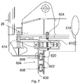
- Fig. 3 shows the fixing screws 14 serving as the fixing means and a seal 13 for watertightly sealing the connection between the unit 2 and the vessel hull 100.
- the clamping pad 115 here has the form of a shallow recess cut into the plate-shaped member 241 which is fixed to the flange 24 and the flange plate portion 26.
- Fig. 3 shows a guide surface 113 which is inclined outwardlywith increasing height of the hoistingchamber.
- the guide surface 113 cooperates with the clamp114 of the clamping means 11.
- the hydraulic cylinder 111 With the cylinder bolt 117the hydraulic cylinder 111 is fixed to the hoisting chamber wall, so that the cylinder 111 can pivot around this cylinder bolt 117.
- an urging means 116 isprovided, which urges the cylinder 111 of the clampingmeans 11 towards the outside of the hoisting chamber so as to ensure that the clamp 114 is always guided by the guide surface 113.
- the clamp 114 sits into the shallow recess 115 as the clamping pad provided on the flange 24, i.e. on the plate-shaped member 241 thereof.
- the hydrauliccylinders 111 are strong enough to securely clamp the unit into its mounted position, so that the position of the unit in regard to the opening in the vessel hull can be securely held or maintained while the fixing means 14 are screwed off.
- the cylinders 111 are provided with locking valves which cut off the fluid connection of the hydraulic cylinder to the hydraulic system in order tomaintain the cylinder in its actual position.
- the clamping may be gradually released.
- the cylinder 111 is controlled so as toslowly retract the rod 112. Because the fixing means 14 have been removed, and due to the differential pressure between inside the hoisting chamber 1 and the water pressure at the bottom of the vessel 100, the flange 24 will move upward following the cylinder rods 112 movement while keeping the engagement between the shallow recess 115 and the clamp 114. Once the seal 13 lifts up from its counter surface, water may rapidly flow into the hoisting chamber 1. After the hoisting chamber is flooded to a required level, the cylinder 111 may be controlled tofurther retract the rod 112.
- the unit further comprises a number of lifting devices 500 arranged in co-operation with the flange 24 and the hoisting chamber 1 in order to apply controllably force to the flange in the upward direction of the hoisting chamber.
- a lifting device is shown the figures2 , 3 , 5 and 6 .
- the lifting devices 500 comprise a number of lifting jacks, particularly hydraulic jacks, arranged under the flange plate portion 26 around the unit 2.
- the lifting devices are preferably arranged substantiallysymmetrically in respect of center of load to be lifted.
- the lifting devices 500 are arranged to fit between an extension of the flange plate portion 26 and a lifting base arranged to the hoisting chamber in a retracted position while the flange 24 sits on the seal 13 with its flange plate portion 26.
- the flange plate portion 26 is provided with a local extension only at the location of the jack 500 against which the jack is supported during the lifting so that the flange portion may pass the guide surface 113.
- Each lifting device is provided with or is in connection with a force control system 510, which facilitates controlling of alignment of the flange while installed or removed.
- the lifting devices may be used during assembly / disassembly of the unit, whether it is a thruster or a closing cover or other kind of unit.
- the hydraulic jacks 500 are activated and the flange 24 is liftedfrom theseat controllably by the hydraulic jacks.
- the flange is lifted so that the cylinders 111 and their rods 112 adjustably control the lifting of the flange and the flange 24 will move upward following the cylinder rods 112 and hydraulic jacks 500 movement while keeping the engagement between the shallow recess 115 and the clamp 114.
- This way the removal of the flange is performed controllably and movement may be kept translational i.e. moving the flange aligned with the opening in the hosting chamber.
- a low tension on the hoisting lines may also be is applied.
- the unit is lifted at a first level,the hydraulic cylinders 111 are fully retracted in to their end position.
- the lift is about 150mm.Once the cylinders have been retracted, following the urging force of the urging means 116, each cylinder 111 will again lie flat or substantially flat against the hoisting chamber wall.
- the unit 2 may then be lifted to be taken out of the hoisting chamber.
- a bottom closing cover 6 (shown figure 4 c) ) may be installed to the hoisting chamber to seal the opening.
- a safety hatch may be installed on top of chamber and the chamber may be emptied i.e. water pumped away.
- the closing cover 6 is arranged of at least two parts, a first part 601 and a second part 602.
- the parts are here called as top part and lower part, because the first part forms a top (inner) portion of the closing cover and the lower part form the lower (outer) portion of the cover.
- the lower part has a form such that it can be fitted into the opening in the bottom of the hoisting chamber through the hull.
- the form may be circular or a polygonal.It is, however, important that particularly the sealing system may properly function at possible corner areas, which are therefore advantageously suitably rounded.
- the upper part has a flange plate portion 26by means of which it may be attached to the chamber.
- the cover 6 is in a position supported by the jacks 500 just before mounting.
- the upper part 601 may at a removed position by dotted line.
- the second part 602 comprises a periphery wall 622 and a water tight inner section 620 bordered by the periphery wall.
- the first part comprising a flange 24 is extending over the periphery wall of the second part, to be outside the area of the lower part 602.
- the first part and the second part are removably attached to each other.
- the periphery wall outer surface of the second part 602 and the flange plate portion lower surface of the first part are perpendicular to each other.
- the upper part extends wider than the lower part.
- the first and the second part are provided with counter surfaces which are joined together when the first and the second part are attached with each other.
- the surfaces are preferably provided with planar counter surfaces.
- FIG 7 there is shown a closing cover according to an embodiment of the invention.
- the lower part is provided with a sealing system 604 at its outer periphery wallsurface 622.
- the sealing system is controllable so that it may be in active state or in passive state. When it is in active state it seals the gap between lower part and the wall of the hoisting chamber.
- the seal units may be inflatable seals so that they may be pressurized by a working fluid when activated and depressurized when deactivated.
- the seals are provided with or are in connectable with a controllable working fluid supply system 618, such as pressurized air / pneumatic system.
- the sealing system 604 is arranged in a connection path 630 from outside of the vessel to inside of the vessel along interconnecting surfaces of the closing cover and the hull of the vessel.
- the lower part 602 is also provided with attaching means to attach the second part 602 to the vessel hull at least when the upper part 601 is removed.
- the attaching means comprises a number of holding means 610.
- the holding means are in this embodiment pins, which may move partially from outer periphery wall surface 622 of the lower part and co-operate with the hoisting chamber, in which a mating recess 614 has been arranged thus, when activated or pushed out, locking the lower part 602 to its locking position in the hoisting chamber.
- the hoisting chamber is provided with a counterpart 614 for each of the holding pin, such as a recess, or a slot, so that the holding pins, when protruding from the wall of the lower part into the pin recess, locks the movement of the lower part.
- the locking pins are arranged to the lower part longitudinally at one side of the sealing system, the part being at inner side i.e. dry side when installed.
- the closing cover When servicing the closing cover while the vessel is floating, the closing cover is attached through its periphery wall 622 to the surrounding opening and the sealing system 604 is activated by inflating the sealing units at the outer cylindrical surface.
- the first part may be removed from the second part by e.g. removing respective screws 624,and any serviceable object revealed by the removing of the first part may be serviced.
- the top part 601 may be removed from the lower part 602 after the sealunits 606, 608 are activated and the holding pins 610 are inserted in to recesses 614 in the counter surface of the hoisting chamber.
- the first part is extending radially from inner side of the periphery wall of the second part to outer side of the periphery wall.
- FIG 8 there is shown a closing cover according to another embodiment of the invention.
- the lower part is also provided with a sealing system 604' at its upper part, on lower surface of a plate 626 on which the upper part 601 is attached.
- the sealing system comprises two successive O-rings 606', 608' in the radial direction of the hoisting chamber.
- the sealing system is arranged in a connection path 630 from outside the vessel to inside of the vessel along interconnecting surfaces of the closing cover and the hull of the vessel.
- the lower part is also in this embodiment provided with a number of holding means 610.
- the holding means are pins in this embodiment, which pins may move partially from outer periphery wall surface 622 of the lower part and co-operate with the hoisting chamber.
- the hoisting chamber is provided with a counterpart 614 for each of the holding pin, such as a recess, or a slot, so that the holding pins, when protruding from the wall of the lower part into the recess, locks the movement of and tightens the sealing system 604' the lower part.
- the locking pins are arranged to the lower part longitudinally at one side of the sealing system, the part being at inner side i.e. dry side when installed.
- the lower part of closing cover When servicing the closing cover while the vessel is floating, the lower part of closing cover is attached through its periphery wall 622 to the surrounding opening tightening the O-rings 606', 608'.
- the first part may be removed from the second part by e.g. removing respective screws 624, and any serviceable object revealed by the removing of the first part may be serviced.
- the top part 601 may be removed from the lower part 602 after the holding pins 610 are securely inserted in to recesses 614 in the counter surface of the hoisting chamber.
- the first part may be is a flange plate extending radially from inner side of the periphery wall of the second part to over the periphery wall.
- the jacks are remounted at their positions explained above.
- the chamber is flooded e.g.with a water pump up to a proper level corresponding the ship's draft.
- the bottom closing cover is demounted in a similar manner explained above in connection with the flange 24.
- the unit will be lowered into the flooded hoisting channel until it lands and rests on the actuated i.e. extended jacks, which are positioned at the bottom of the channel. Then, the cylinders 111 are controlled to extend their rods 112 and, guided by the guide surface 113, each clamp 114 will move into engagement with the shallow recesses 115 on the flange 24. Now the working pressure on each hydraulic jack can be released in a controlled manner and the jacks will be retracted down with appropriately low actuating pressure on the cylinders111. This takes place while the hoisting chamber is filled with water.When the clamping means have clamped the unit 2 into the mounted position, water can be pumped out of the hoisting chamber so as to dry the working space there. It is noted that the cylinders of clamping means are also maintained ina locked state, for safety reasons.
- connection path 630 which runs through a potential route to the water underneath the vessel from outside the vessel to inside of the vessel along interconnecting surfaces of the unit 2 or the flange thereof and the hull of the vessel 100.
- sealing system 604 which divides the connection path 630 to outside connection path portion 630' and inside connection path portion 630".
- the outer side connection pathportion 630' opens into the surroundings i.e. water when the vessel is floating.
- the unit 2 is provided with a gas inlet system 640, 640'arranged to open into the outside connection path portion 630'.
- the gas inlet system 640, 640' comprises a conduit 642, 642' extending through the unit or though the hull and is connectable to a source of gas 644 arranged in the vessel.
- the source of gas is advantageously a pressurized air system of the vessel.
- the source of gas may also comprise an air-nitrogen converter 645, in which case the gas which is fed to the space is advantageously nitrogen.
- the gas inlet system is arranged to inject dry nitrogen into the space, so that a pressure above the water hydrostatic pressure at prevailing draft is controllably maintained in the outside connection path portion. This prevents any sea growth in the space and also prevents sea water to enter into the space.
- Advantageously only service air is needed to feed this system.
- control system 646, 646' for maintaining a predetermined supply of gas to the inlet gas system.
- the control system may comprise e.g. a pressure sensor.
- the control system may comprise e.g. a valve 646, 646' and or an orifice plate 647.Naturally only one inlet system is needed and the separated conduits in figure 5 are for purpose of example.
- Fig. 4 shows a sequence of steps a), b), c) inwhich a unit in the form of a thruster 2 is dismounted froma vessel hull 100.
- a step a) is shown in which the electric drive motor 23 is removed from the thruster 2.
- cover 61 or covers are mounted to the thruster 2 toclose all openings against the immersion of water when the hoisting chamber 1 is to be flooded.
- the drive connection of the thruster 2 usually consists of a flexible coupling; it may however also or additionally include a gear box.
- a hoist means 7 is already fixed to the flange 24 of the thruster 2 as is indicated at the right lifting eye in step a) of Fig. 4 .
- the clamping means are activated so as to clamp the flange 24 against its seat in the vessel hull 100. Once the clamping is set, the fixing means (screws) can be removed and thepersons leave the hoisting chamber.
- the clamping means is gradually released so as to let water flow into the hoisting chamber.
- the clampingmeans can be released and the lifting devices activated, that is, as described under reference to Fig. 3 , the rods of the cylinders are retracted.
- the hoist means 7 of a crane 5 are used to pull up the thruster 2 by lifting it at the lifting eyes.
- the thruster 2 is guided in the hoisting chamberby means of the guide rails which are indicated withseveral parallel lines on the chamber walls in step b) ofFig.
- step c) in Fig. 4 will be established in that a provisional cover 6 isinserted into the hoist chamber so as to close the openingin the vessel hull using the flange seat at the bottom of the chamber. It is noted that clamping with the clamping means is possible because the cover 6 has the same clamping pads as are provided with the flange 24 of thethruster 2. Depending on how long the hoisting chamber has to stay closed, the cover may be additionally fixed with fixing means after the water has been removed from the chamber. Basically, however, it should be sufficient to press the cover down by a clamping means. Also, an additionalcover 4 is put on the top of the hoisting chamber for safety reasons as discussed above.
- Fig. 4 dismounting the thruster and putting it on deck of the vessel has been described. Mounting of the thrusterafter maintenance or for replacement is done in the opposite order of steps. That is: removing cover 4,clamping cover 6, fixing hoist means 7 to cover 6, removing any fixing means (if any), and gradually releasing the clamping force so as to flood the hoisting chamber 1. Once the required water level is reached in hoisting chamber 1, coveris lifted after clamping has been released. The cover 6 is removed from hoisting chamber 6.Then, proceeding back to step b), the thruster 2 fixed to the hoist means 7 will be led down the hoisting chamber 1 while being guided by the guide rails 12.
- clamping means 111, 112,114, 115 are activated to press the flange 24 of the thruster 2 against its seat to seal the bottom of the hoisting chamber 1.
- the hoisting chamber 1 is thenpumped empty and in the dry space fixing means like screws are set and fixed. After that, clamping may be released.
- Hoist means 7 are separated from the lifting eyes of the thruster and covers 61 are removed. Thereafter, theelectric motor 23 can be lowered into position and fixed for operation. After connection work has been done, the thruster 2 is ready for use again.
Landscapes
- Engineering & Computer Science (AREA)
- Mechanical Engineering (AREA)
- Chemical & Material Sciences (AREA)
- Combustion & Propulsion (AREA)
- Ocean & Marine Engineering (AREA)
- Pressure Vessels And Lids Thereof (AREA)
- Actuator (AREA)
- Load-Engaging Elements For Cranes (AREA)
- Earth Drilling (AREA)
- Jib Cranes (AREA)
- Life Sciences & Earth Sciences (AREA)
- Geology (AREA)
- Structural Engineering (AREA)
Claims (13)
- Verfahren zur Handhabung einer Einheit in einer wasserdichten Förderkammer, die in einem Rumpf eines Schiffs mündet, wobei die Einheit dazu eingerichtet ist, sich in das Wasser unter dem Schiff zu erstrecken, wenn sie in ihrer montierten Position installiert ist, wobei das Verfahren durch die folgenden Schritte gekennzeichnet ist:Klemmen der Einheit (2) in ihrer montierten Position durch ein Klemmmittel (11),Lösen von Befestigungsmitteln (14), die die Einheit (2) in ihrer montierten Position befestigen, während die Einheit (2) durch das Klemmmittel (11) in Position geklemmt wird,zumindest partielles Fluten der Förderkammer (1),Abziehen der Einheit (2) durch gleichzeitiges Lösen des Klemmmittels (11) und Anheben der Einheit (2) aus ihrer montierten Position durch Anwenden von Hebekraft auf die Einheit (2) durch Hebevorrichtungen (500) undHieven der Einheit (2) von der Förderkammer (1) weg.
- Verfahren nach Anspruch 1, gekennzeichnet durch einen weiteren Schritt des Steuerns des Abziehens der Einheit (2) durch gemeinsame Betätigung des Klemmmittels (11) und der Hebevorrichtungen (500).
- Verfahren nach Anspruch 1 oder 2, gekennzeichnet durch einen weiteren Schritt des Steuerns einer Ausrichtung während des Abziehens der Einheit (2) durch gemeinsame Betätigung des Klemmmittels (11) und der Hebevorrichtungen (500).
- Verfahren nach Anspruch 1, dadurch gekennzeichnet, dass das Fluten der Förderkammer (1) einen Schritt des allmählichen Lösens des Klemmmittels (11), die die Einheit (2) in die montierte Position klemmen, in Zusammenwirkung mit den Hebevorrichtungen (500) umfasst, bis Wasser durch die Öffnung des Rumpfs (100) eintritt.
- Verfahren nach Anspruch 1, dadurch gekennzeichnet, dass das Klemmen und das Anheben der Einheit (2) Hydraulikkräfte verwenden.
- Verfahren nach Anspruch 1, gekennzeichnet durch die weiteren folgenden Schritte:Absenken der Einheit (2) in ihre montierte Position im Inneren der Förderkammer (1) auf den Hebevorrichtungen (500),Klemmen der Einheit (2) in ihrer montierten Position und Schließen der Öffnung in dem Schiffsrumpf (100) mit Zusammenwirkung des Klemmmittels (11) und der Hebevorrichtungen (500),zumindest partielles Entfernen des Wassers aus der Förderkammer (1) und Anwenden von Befestigungsmitteln (14), wodurch die Einheit (2) in ihrer montierten Position befestigt wird,Lösen des Klemmens der Einheit (2).
- Verfahren zur Handhabung einer Einheit in einer wasserdichten Förderkammer, die in einem Rumpf eines Schiffs mündet, wobei die Einheit (2) dazu eingerichtet ist, sich in das Wasser unter dem Schiff zu erstrecken, wenn sie in ihrer montierten Position installiert ist, wobei das Verfahren durch die folgenden Schritte gekennzeichnet ist:Absenken der Einheit (2) in ihre montierte Position im Inneren der Förderkammer (1) auf Hebevorrichtungen (500),Klemmen der Einheit (2) in ihrer montierten Position und Schließen der Öffnung in dem Schiffsrumpf (100) mit Zusammenwirkung des Klemmmittels (11) und der Hebevorrichtungen (500),zumindest partielles Entfernen des Wassers aus der Förderkammer (1) und Anwenden von Befestigungsmitteln (14), wodurch die Einheit (2) in ihrer montierten Position befestigt wird,Lösen des Klemmens der Einheit (2).
- Verfahren nach Anspruch 6 oder 7, gekennzeichnet durch einen weiteren Schritt des Steuerns der Installation der Einheit (2) durch gemeinsame Betätigung des Klemmmittels (11) und der Hebevorrichtungen (500).
- Verfahren nach Anspruch 7, gekennzeichnet durch einen weiteren Schritt des Steuerns einer Ausrichtung während der Installation der Einheit (2) durch gemeinsame Betätigung des Klemmmittels (11) und der Hebevorrichtungen (500).
- Baugruppe in einem Seeschiff, das eine wasserdichte Förderkammer, die in einem Rumpf eines Schiffs mündet, und eine Einheit, die eine Öffnung der Förderkammer in einem Schiffsrumpf schließt, umfasst, wobei die Einheit dazu eingerichtet ist, sich in das Wasser unter dem Schiff zu erstrecken, wobei die Baugruppe Folgendes umfasst:ein Klemmmittel (11), das dazu eingerichtet ist, die Einheit (2) in ihrer montierten Position zu klemmen, und Hebevorrichtungen (500), die in Zusammenwirkung mit der Einheit (2) und der Förderkammer (1) angeordnet sind, um eine Kraft auf die Einheit (2) anzuwenden, dadurch gekennzeichnet, dass die Baugruppe weiterhin ein Befestigungsmittel (14) umfasst, das die Einheit (2) in ihrer montierten Position befestigt, und dass die Hebevorrichtungen (500) mehrere hydraulische Winden umfassen, die im Inneren der Förderkammer (1) und um die Öffnung in dem Rumpf (100) angeordnet sind, wenn die Förderkammer (1) montiert ist.
- Baugruppe nach Anspruch 10, wobei die Hebevorrichtungen (500) an dem Rumpf (100) befestigt sind.
- Baugruppe nach Anspruch 10, wobei die Hebevorrichtungen (500) entfernbare hydraulische Winden umfassen.
- Baugruppe nach einem der vorhergehenden Ansprüche 10-12, wobei die Hebevorrichtungen (500) dedizierte Kraftsteuersysteme (510) umfassen.
Applications Claiming Priority (1)
| Application Number | Priority Date | Filing Date | Title |
|---|---|---|---|
| PCT/FI2012/050991 WO2014060634A1 (en) | 2012-10-16 | 2012-10-16 | Method of handling a unit in a marine vessel and an assembly in a marine vessel |
Publications (2)
| Publication Number | Publication Date |
|---|---|
| EP2909080A1 EP2909080A1 (de) | 2015-08-26 |
| EP2909080B1 true EP2909080B1 (de) | 2017-01-18 |
Family
ID=47263393
Family Applications (1)
| Application Number | Title | Priority Date | Filing Date |
|---|---|---|---|
| EP12794354.6A Active EP2909080B1 (de) | 2012-10-16 | 2012-10-16 | Verfahren zur handhabung einer einheit in einem wasserfahrzeug und einer anordnung in einem wasserfahrzeug |
Country Status (6)
| Country | Link |
|---|---|
| US (1) | US10124860B2 (de) |
| EP (1) | EP2909080B1 (de) |
| JP (1) | JP5997843B2 (de) |
| KR (1) | KR101680504B1 (de) |
| CN (1) | CN104768845B (de) |
| WO (1) | WO2014060634A1 (de) |
Families Citing this family (1)
| Publication number | Priority date | Publication date | Assignee | Title |
|---|---|---|---|---|
| CN113511312B (zh) * | 2021-04-23 | 2022-05-10 | 中船黄埔文冲船舶有限公司 | 船舶艏辅推装置的安装方法 |
Family Cites Families (16)
| Publication number | Priority date | Publication date | Assignee | Title |
|---|---|---|---|---|
| SE419325B (sv) * | 1976-06-11 | 1981-07-27 | Resmastservice Ab | Sett for att lasta och lossa tunga kollin pa fartyg samt anordning for settets genomforande |
| JPS591038Y2 (ja) * | 1979-08-06 | 1984-01-12 | 川崎重工業株式会社 | 旋回式スラスタ固定装置 |
| JPH0558592A (ja) * | 1991-09-04 | 1993-03-09 | Osaka Jack Seisakusho:Kk | 油圧ジヤツキ装置及び油圧ジヤツキ装置の同調作動方法 |
| JP3561758B2 (ja) * | 1995-10-31 | 2004-09-02 | 株式会社フジタ | 昇降装置 |
| US6067697A (en) * | 1996-01-24 | 2000-05-30 | Kamewa Finland Oy | Method for removing a propeller assembly from and for mounting the same in an opening in the bottom of a swimming vessel |
| FI103194B (fi) | 1996-01-24 | 1999-05-14 | Kamewa Finland Ltd | Menetelmä ja laitteisto potkurilaitteen irrottamiseksi uivan aluksen p ohjassa olevasta aukosta ja asentamiseksi siihen |
| JP2001171986A (ja) * | 1999-12-21 | 2001-06-26 | Sumikin Transport Service Co Ltd | 重量構造物の嵩上げ装置及び該装置を用いたジャッキアップ工法 |
| US6394014B1 (en) * | 2000-09-12 | 2002-05-28 | William L. Waldock | Marine vessel and method of manufacturing |
| US7234983B2 (en) * | 2005-10-21 | 2007-06-26 | Brunswick Corporation | Protective marine vessel and drive |
| WO2010100313A1 (en) * | 2009-03-05 | 2010-09-10 | Beacon Finland Ltd Oy | Service space for a retractable propulsion device or corresponding |
| JP2012528030A (ja) | 2009-05-28 | 2012-11-12 | ショッテル ゲゼルシャフトミットベシュレンクターハフトゥング | ラダープロペラ船舶推進システム及び当該システムを装備した船舶、並びに当該システムの組み立て及び分解処理方法 |
| JP5568128B2 (ja) * | 2010-04-16 | 2014-08-06 | ワルトシラ フィンランド オサケユキチュア | 推進装置の搭載方法 |
| US7992275B1 (en) * | 2010-09-16 | 2011-08-09 | Thrustmaster of Texas, Inc. | Method for thruster withdrawal for maintenance or vessel transit without the need for an external crane, remote operated vehicle, or diver |
| WO2012058694A2 (en) | 2010-10-31 | 2012-05-03 | Trustees Of Boston University | Blood glucose control system |
| JP2012101580A (ja) * | 2010-11-08 | 2012-05-31 | Mitsubishi Heavy Ind Ltd | 洋上における推進装置のメンテナンス方法 |
| JP5997844B2 (ja) * | 2012-10-16 | 2016-09-28 | ワルトシラ ネザーランズ ベー フェー | 海洋船内の船体内のホイストチャンバーの下部を閉鎖するための閉鎖カバー及びホイストチャンバー内の下部にアクセスすることを容易にする方法 |
-
2012
- 2012-10-16 CN CN201280076182.XA patent/CN104768845B/zh active Active
- 2012-10-16 WO PCT/FI2012/050991 patent/WO2014060634A1/en not_active Ceased
- 2012-10-16 KR KR1020157011549A patent/KR101680504B1/ko active Active
- 2012-10-16 JP JP2015537310A patent/JP5997843B2/ja not_active Expired - Fee Related
- 2012-10-16 US US14/433,322 patent/US10124860B2/en active Active
- 2012-10-16 EP EP12794354.6A patent/EP2909080B1/de active Active
Non-Patent Citations (1)
| Title |
|---|
| None * |
Also Published As
| Publication number | Publication date |
|---|---|
| CN104768845B (zh) | 2017-04-19 |
| CN104768845A (zh) | 2015-07-08 |
| JP2015532241A (ja) | 2015-11-09 |
| WO2014060634A1 (en) | 2014-04-24 |
| EP2909080A1 (de) | 2015-08-26 |
| US20150284052A1 (en) | 2015-10-08 |
| KR20150070211A (ko) | 2015-06-24 |
| US10124860B2 (en) | 2018-11-13 |
| JP5997843B2 (ja) | 2016-09-28 |
| KR101680504B1 (ko) | 2016-11-28 |
Similar Documents
| Publication | Publication Date | Title |
|---|---|---|
| US8926382B2 (en) | Mounting method of thruster | |
| EP2477888B1 (de) | Schiff mit einziehbarem antrieb | |
| EP2931600B1 (de) | Verfahren zur demontage und/oder montage eines unterwasserabschnitts einer einziehbaren strahlrudereinheit | |
| EP2909082B1 (de) | Strahlruderanordnung in einem wasserfahrzeug | |
| EP2909081B1 (de) | Verschlussdeckel zum schliessen des unteren teils einer hebekammer in der hülle eines wasserfahrzeugs und verfahren zur ermöglichung des zugangs zum unteren teil der hebekammer | |
| EP2909080B1 (de) | Verfahren zur handhabung einer einheit in einem wasserfahrzeug und einer anordnung in einem wasserfahrzeug | |
| EP2610160B1 (de) | System zum Anheben von Propellergondeln zur Bereitstellung der Wartung von Propellergondeln von schwimmenden Schiffskörpern | |
| CN104781139B (zh) | 船舶中的推进器组件 | |
| HK1212956B (en) | Method for disassembling and/or assembling an underwater section of a retractable thruster unit |
Legal Events
| Date | Code | Title | Description |
|---|---|---|---|
| PUAI | Public reference made under article 153(3) epc to a published international application that has entered the european phase |
Free format text: ORIGINAL CODE: 0009012 |
|
| 17P | Request for examination filed |
Effective date: 20150428 |
|
| AK | Designated contracting states |
Kind code of ref document: A1 Designated state(s): AL AT BE BG CH CY CZ DE DK EE ES FI FR GB GR HR HU IE IS IT LI LT LU LV MC MK MT NL NO PL PT RO RS SE SI SK SM TR |
|
| AX | Request for extension of the european patent |
Extension state: BA ME |
|
| DAX | Request for extension of the european patent (deleted) | ||
| 17Q | First examination report despatched |
Effective date: 20160524 |
|
| GRAP | Despatch of communication of intention to grant a patent |
Free format text: ORIGINAL CODE: EPIDOSNIGR1 |
|
| INTG | Intention to grant announced |
Effective date: 20160922 |
|
| GRAS | Grant fee paid |
Free format text: ORIGINAL CODE: EPIDOSNIGR3 |
|
| GRAA | (expected) grant |
Free format text: ORIGINAL CODE: 0009210 |
|
| RAP1 | Party data changed (applicant data changed or rights of an application transferred) |
Owner name: WAERTSILAE NETHERLANDS B.V. |
|
| RIN1 | Information on inventor provided before grant (corrected) |
Inventor name: VAN DER KAM, AAD |
|
| AK | Designated contracting states |
Kind code of ref document: B1 Designated state(s): AL AT BE BG CH CY CZ DE DK EE ES FI FR GB GR HR HU IE IS IT LI LT LU LV MC MK MT NL NO PL PT RO RS SE SI SK SM TR |
|
| REG | Reference to a national code |
Ref country code: GB Ref legal event code: FG4D |
|
| REG | Reference to a national code |
Ref country code: CH Ref legal event code: EP |
|
| REG | Reference to a national code |
Ref country code: AT Ref legal event code: REF Ref document number: 862730 Country of ref document: AT Kind code of ref document: T Effective date: 20170215 |
|
| REG | Reference to a national code |
Ref country code: IE Ref legal event code: FG4D |
|
| REG | Reference to a national code |
Ref country code: DE Ref legal event code: R096 Ref document number: 602012028046 Country of ref document: DE |
|
| REG | Reference to a national code |
Ref country code: NL Ref legal event code: FP |
|
| REG | Reference to a national code |
Ref country code: NO Ref legal event code: T2 Effective date: 20170118 |
|
| REG | Reference to a national code |
Ref country code: LT Ref legal event code: MG4D |
|
| REG | Reference to a national code |
Ref country code: AT Ref legal event code: MK05 Ref document number: 862730 Country of ref document: AT Kind code of ref document: T Effective date: 20170118 |
|
| PG25 | Lapsed in a contracting state [announced via postgrant information from national office to epo] |
Ref country code: GR Free format text: LAPSE BECAUSE OF FAILURE TO SUBMIT A TRANSLATION OF THE DESCRIPTION OR TO PAY THE FEE WITHIN THE PRESCRIBED TIME-LIMIT Effective date: 20170419 Ref country code: LT Free format text: LAPSE BECAUSE OF FAILURE TO SUBMIT A TRANSLATION OF THE DESCRIPTION OR TO PAY THE FEE WITHIN THE PRESCRIBED TIME-LIMIT Effective date: 20170118 Ref country code: HR Free format text: LAPSE BECAUSE OF FAILURE TO SUBMIT A TRANSLATION OF THE DESCRIPTION OR TO PAY THE FEE WITHIN THE PRESCRIBED TIME-LIMIT Effective date: 20170118 Ref country code: IS Free format text: LAPSE BECAUSE OF FAILURE TO SUBMIT A TRANSLATION OF THE DESCRIPTION OR TO PAY THE FEE WITHIN THE PRESCRIBED TIME-LIMIT Effective date: 20170518 |
|
| PG25 | Lapsed in a contracting state [announced via postgrant information from national office to epo] |
Ref country code: LV Free format text: LAPSE BECAUSE OF FAILURE TO SUBMIT A TRANSLATION OF THE DESCRIPTION OR TO PAY THE FEE WITHIN THE PRESCRIBED TIME-LIMIT Effective date: 20170118 Ref country code: ES Free format text: LAPSE BECAUSE OF FAILURE TO SUBMIT A TRANSLATION OF THE DESCRIPTION OR TO PAY THE FEE WITHIN THE PRESCRIBED TIME-LIMIT Effective date: 20170118 Ref country code: BG Free format text: LAPSE BECAUSE OF FAILURE TO SUBMIT A TRANSLATION OF THE DESCRIPTION OR TO PAY THE FEE WITHIN THE PRESCRIBED TIME-LIMIT Effective date: 20170418 Ref country code: AT Free format text: LAPSE BECAUSE OF FAILURE TO SUBMIT A TRANSLATION OF THE DESCRIPTION OR TO PAY THE FEE WITHIN THE PRESCRIBED TIME-LIMIT Effective date: 20170118 Ref country code: RS Free format text: LAPSE BECAUSE OF FAILURE TO SUBMIT A TRANSLATION OF THE DESCRIPTION OR TO PAY THE FEE WITHIN THE PRESCRIBED TIME-LIMIT Effective date: 20170118 Ref country code: SE Free format text: LAPSE BECAUSE OF FAILURE TO SUBMIT A TRANSLATION OF THE DESCRIPTION OR TO PAY THE FEE WITHIN THE PRESCRIBED TIME-LIMIT Effective date: 20170118 Ref country code: PL Free format text: LAPSE BECAUSE OF FAILURE TO SUBMIT A TRANSLATION OF THE DESCRIPTION OR TO PAY THE FEE WITHIN THE PRESCRIBED TIME-LIMIT Effective date: 20170118 Ref country code: PT Free format text: LAPSE BECAUSE OF FAILURE TO SUBMIT A TRANSLATION OF THE DESCRIPTION OR TO PAY THE FEE WITHIN THE PRESCRIBED TIME-LIMIT Effective date: 20170518 |
|
| REG | Reference to a national code |
Ref country code: FR Ref legal event code: PLFP Year of fee payment: 6 |
|
| REG | Reference to a national code |
Ref country code: DE Ref legal event code: R097 Ref document number: 602012028046 Country of ref document: DE |
|
| PG25 | Lapsed in a contracting state [announced via postgrant information from national office to epo] |
Ref country code: CZ Free format text: LAPSE BECAUSE OF FAILURE TO SUBMIT A TRANSLATION OF THE DESCRIPTION OR TO PAY THE FEE WITHIN THE PRESCRIBED TIME-LIMIT Effective date: 20170118 Ref country code: SK Free format text: LAPSE BECAUSE OF FAILURE TO SUBMIT A TRANSLATION OF THE DESCRIPTION OR TO PAY THE FEE WITHIN THE PRESCRIBED TIME-LIMIT Effective date: 20170118 Ref country code: RO Free format text: LAPSE BECAUSE OF FAILURE TO SUBMIT A TRANSLATION OF THE DESCRIPTION OR TO PAY THE FEE WITHIN THE PRESCRIBED TIME-LIMIT Effective date: 20170118 Ref country code: EE Free format text: LAPSE BECAUSE OF FAILURE TO SUBMIT A TRANSLATION OF THE DESCRIPTION OR TO PAY THE FEE WITHIN THE PRESCRIBED TIME-LIMIT Effective date: 20170118 |
|
| PLBE | No opposition filed within time limit |
Free format text: ORIGINAL CODE: 0009261 |
|
| STAA | Information on the status of an ep patent application or granted ep patent |
Free format text: STATUS: NO OPPOSITION FILED WITHIN TIME LIMIT |
|
| PG25 | Lapsed in a contracting state [announced via postgrant information from national office to epo] |
Ref country code: SM Free format text: LAPSE BECAUSE OF FAILURE TO SUBMIT A TRANSLATION OF THE DESCRIPTION OR TO PAY THE FEE WITHIN THE PRESCRIBED TIME-LIMIT Effective date: 20170118 Ref country code: DK Free format text: LAPSE BECAUSE OF FAILURE TO SUBMIT A TRANSLATION OF THE DESCRIPTION OR TO PAY THE FEE WITHIN THE PRESCRIBED TIME-LIMIT Effective date: 20170118 |
|
| 26N | No opposition filed |
Effective date: 20171019 |
|
| PG25 | Lapsed in a contracting state [announced via postgrant information from national office to epo] |
Ref country code: SI Free format text: LAPSE BECAUSE OF FAILURE TO SUBMIT A TRANSLATION OF THE DESCRIPTION OR TO PAY THE FEE WITHIN THE PRESCRIBED TIME-LIMIT Effective date: 20170118 |
|
| PG25 | Lapsed in a contracting state [announced via postgrant information from national office to epo] |
Ref country code: MC Free format text: LAPSE BECAUSE OF FAILURE TO SUBMIT A TRANSLATION OF THE DESCRIPTION OR TO PAY THE FEE WITHIN THE PRESCRIBED TIME-LIMIT Effective date: 20170118 |
|
| REG | Reference to a national code |
Ref country code: CH Ref legal event code: PL |
|
| REG | Reference to a national code |
Ref country code: IE Ref legal event code: MM4A |
|
| PG25 | Lapsed in a contracting state [announced via postgrant information from national office to epo] |
Ref country code: CH Free format text: LAPSE BECAUSE OF NON-PAYMENT OF DUE FEES Effective date: 20171031 Ref country code: LI Free format text: LAPSE BECAUSE OF NON-PAYMENT OF DUE FEES Effective date: 20171031 Ref country code: LU Free format text: LAPSE BECAUSE OF NON-PAYMENT OF DUE FEES Effective date: 20171016 |
|
| REG | Reference to a national code |
Ref country code: BE Ref legal event code: MM Effective date: 20171031 |
|
| PG25 | Lapsed in a contracting state [announced via postgrant information from national office to epo] |
Ref country code: BE Free format text: LAPSE BECAUSE OF NON-PAYMENT OF DUE FEES Effective date: 20171031 |
|
| PG25 | Lapsed in a contracting state [announced via postgrant information from national office to epo] |
Ref country code: MT Free format text: LAPSE BECAUSE OF NON-PAYMENT OF DUE FEES Effective date: 20171016 |
|
| REG | Reference to a national code |
Ref country code: FR Ref legal event code: PLFP Year of fee payment: 7 |
|
| PG25 | Lapsed in a contracting state [announced via postgrant information from national office to epo] |
Ref country code: IE Free format text: LAPSE BECAUSE OF NON-PAYMENT OF DUE FEES Effective date: 20171016 |
|
| PG25 | Lapsed in a contracting state [announced via postgrant information from national office to epo] |
Ref country code: HU Free format text: LAPSE BECAUSE OF FAILURE TO SUBMIT A TRANSLATION OF THE DESCRIPTION OR TO PAY THE FEE WITHIN THE PRESCRIBED TIME-LIMIT; INVALID AB INITIO Effective date: 20121016 |
|
| PG25 | Lapsed in a contracting state [announced via postgrant information from national office to epo] |
Ref country code: CY Free format text: LAPSE BECAUSE OF FAILURE TO SUBMIT A TRANSLATION OF THE DESCRIPTION OR TO PAY THE FEE WITHIN THE PRESCRIBED TIME-LIMIT Effective date: 20170118 |
|
| PG25 | Lapsed in a contracting state [announced via postgrant information from national office to epo] |
Ref country code: MK Free format text: LAPSE BECAUSE OF FAILURE TO SUBMIT A TRANSLATION OF THE DESCRIPTION OR TO PAY THE FEE WITHIN THE PRESCRIBED TIME-LIMIT Effective date: 20170118 |
|
| PGFP | Annual fee paid to national office [announced via postgrant information from national office to epo] |
Ref country code: NL Payment date: 20191021 Year of fee payment: 8 Ref country code: DE Payment date: 20191021 Year of fee payment: 8 |
|
| PGFP | Annual fee paid to national office [announced via postgrant information from national office to epo] |
Ref country code: FR Payment date: 20191028 Year of fee payment: 8 Ref country code: IT Payment date: 20191028 Year of fee payment: 8 |
|
| PG25 | Lapsed in a contracting state [announced via postgrant information from national office to epo] |
Ref country code: TR Free format text: LAPSE BECAUSE OF FAILURE TO SUBMIT A TRANSLATION OF THE DESCRIPTION OR TO PAY THE FEE WITHIN THE PRESCRIBED TIME-LIMIT Effective date: 20170118 |
|
| PGFP | Annual fee paid to national office [announced via postgrant information from national office to epo] |
Ref country code: GB Payment date: 20191021 Year of fee payment: 8 |
|
| PG25 | Lapsed in a contracting state [announced via postgrant information from national office to epo] |
Ref country code: AL Free format text: LAPSE BECAUSE OF FAILURE TO SUBMIT A TRANSLATION OF THE DESCRIPTION OR TO PAY THE FEE WITHIN THE PRESCRIBED TIME-LIMIT Effective date: 20170118 |
|
| REG | Reference to a national code |
Ref country code: DE Ref legal event code: R119 Ref document number: 602012028046 Country of ref document: DE |
|
| REG | Reference to a national code |
Ref country code: NL Ref legal event code: MM Effective date: 20201101 |
|
| GBPC | Gb: european patent ceased through non-payment of renewal fee |
Effective date: 20201016 |
|
| PG25 | Lapsed in a contracting state [announced via postgrant information from national office to epo] |
Ref country code: DE Free format text: LAPSE BECAUSE OF NON-PAYMENT OF DUE FEES Effective date: 20210501 Ref country code: NL Free format text: LAPSE BECAUSE OF NON-PAYMENT OF DUE FEES Effective date: 20201101 Ref country code: FR Free format text: LAPSE BECAUSE OF NON-PAYMENT OF DUE FEES Effective date: 20201031 |
|
| PG25 | Lapsed in a contracting state [announced via postgrant information from national office to epo] |
Ref country code: GB Free format text: LAPSE BECAUSE OF NON-PAYMENT OF DUE FEES Effective date: 20201016 |
|
| PG25 | Lapsed in a contracting state [announced via postgrant information from national office to epo] |
Ref country code: IT Free format text: LAPSE BECAUSE OF NON-PAYMENT OF DUE FEES Effective date: 20201016 |
|
| PGFP | Annual fee paid to national office [announced via postgrant information from national office to epo] |
Ref country code: NO Payment date: 20251024 Year of fee payment: 14 |
|
| PGFP | Annual fee paid to national office [announced via postgrant information from national office to epo] |
Ref country code: FI Payment date: 20251028 Year of fee payment: 14 |