EP2909040B1 - Optically variable surface pattern - Google Patents
Optically variable surface pattern Download PDFInfo
- Publication number
- EP2909040B1 EP2909040B1 EP13779743.7A EP13779743A EP2909040B1 EP 2909040 B1 EP2909040 B1 EP 2909040B1 EP 13779743 A EP13779743 A EP 13779743A EP 2909040 B1 EP2909040 B1 EP 2909040B1
- Authority
- EP
- European Patent Office
- Prior art keywords
- layer
- optically variable
- surface pattern
- variable surface
- micromirrors
- Prior art date
- Legal status (The legal status is an assumption and is not a legal conclusion. Google has not performed a legal analysis and makes no representation as to the accuracy of the status listed.)
- Active
Links
- 238000000576 coating method Methods 0.000 claims description 66
- 239000011248 coating agent Substances 0.000 claims description 65
- 238000004049 embossing Methods 0.000 claims description 32
- 230000000694 effects Effects 0.000 claims description 27
- 239000003086 colorant Substances 0.000 claims description 12
- 239000004973 liquid crystal related substance Substances 0.000 claims description 6
- 239000000463 material Substances 0.000 claims description 6
- 239000010409 thin film Substances 0.000 claims description 5
- 238000001429 visible spectrum Methods 0.000 claims description 4
- 239000004065 semiconductor Substances 0.000 claims description 2
- 239000010410 layer Substances 0.000 description 125
- 239000004922 lacquer Substances 0.000 description 34
- 239000010408 film Substances 0.000 description 9
- 238000005096 rolling process Methods 0.000 description 9
- 239000002131 composite material Substances 0.000 description 6
- 229910052751 metal Inorganic materials 0.000 description 6
- 239000002184 metal Substances 0.000 description 6
- 239000006096 absorbing agent Substances 0.000 description 5
- 239000011888 foil Substances 0.000 description 5
- 230000003287 optical effect Effects 0.000 description 5
- 230000001681 protective effect Effects 0.000 description 5
- -1 polyethylene Polymers 0.000 description 4
- 229910052782 aluminium Inorganic materials 0.000 description 3
- 230000005540 biological transmission Effects 0.000 description 3
- 230000000295 complement effect Effects 0.000 description 3
- 229910052802 copper Inorganic materials 0.000 description 3
- 239000010949 copper Substances 0.000 description 3
- 238000004519 manufacturing process Methods 0.000 description 3
- 238000005086 pumping Methods 0.000 description 3
- 239000000758 substrate Substances 0.000 description 3
- 239000002966 varnish Substances 0.000 description 3
- PXHVJJICTQNCMI-UHFFFAOYSA-N Nickel Chemical compound [Ni] PXHVJJICTQNCMI-UHFFFAOYSA-N 0.000 description 2
- KDLHZDBZIXYQEI-UHFFFAOYSA-N Palladium Chemical compound [Pd] KDLHZDBZIXYQEI-UHFFFAOYSA-N 0.000 description 2
- 239000004952 Polyamide Substances 0.000 description 2
- 239000004698 Polyethylene Substances 0.000 description 2
- 239000004743 Polypropylene Substances 0.000 description 2
- 239000006117 anti-reflective coating Substances 0.000 description 2
- 229910052804 chromium Inorganic materials 0.000 description 2
- 239000011651 chromium Substances 0.000 description 2
- 238000011161 development Methods 0.000 description 2
- 230000018109 developmental process Effects 0.000 description 2
- 239000003989 dielectric material Substances 0.000 description 2
- 229910052737 gold Inorganic materials 0.000 description 2
- 239000010931 gold Substances 0.000 description 2
- 230000001788 irregular Effects 0.000 description 2
- 239000012939 laminating adhesive Substances 0.000 description 2
- 239000002086 nanomaterial Substances 0.000 description 2
- 230000000737 periodic effect Effects 0.000 description 2
- 229920002647 polyamide Polymers 0.000 description 2
- 229920001707 polybutylene terephthalate Polymers 0.000 description 2
- 229920000573 polyethylene Polymers 0.000 description 2
- 229920000139 polyethylene terephthalate Polymers 0.000 description 2
- 239000005020 polyethylene terephthalate Substances 0.000 description 2
- 229920001155 polypropylene Polymers 0.000 description 2
- 229910052709 silver Inorganic materials 0.000 description 2
- VYZAMTAEIAYCRO-UHFFFAOYSA-N Chromium Chemical compound [Cr] VYZAMTAEIAYCRO-UHFFFAOYSA-N 0.000 description 1
- RYGMFSIKBFXOCR-UHFFFAOYSA-N Copper Chemical compound [Cu] RYGMFSIKBFXOCR-UHFFFAOYSA-N 0.000 description 1
- 229910004298 SiO 2 Inorganic materials 0.000 description 1
- BQCADISMDOOEFD-UHFFFAOYSA-N Silver Chemical compound [Ag] BQCADISMDOOEFD-UHFFFAOYSA-N 0.000 description 1
- 229910010413 TiO 2 Inorganic materials 0.000 description 1
- 238000010521 absorption reaction Methods 0.000 description 1
- 229910045601 alloy Inorganic materials 0.000 description 1
- 239000000956 alloy Substances 0.000 description 1
- XAGFODPZIPBFFR-UHFFFAOYSA-N aluminium Chemical compound [Al] XAGFODPZIPBFFR-UHFFFAOYSA-N 0.000 description 1
- 230000015572 biosynthetic process Effects 0.000 description 1
- 238000005352 clarification Methods 0.000 description 1
- 239000011247 coating layer Substances 0.000 description 1
- 238000009500 colour coating Methods 0.000 description 1
- 238000010017 direct printing Methods 0.000 description 1
- PCHJSUWPFVWCPO-UHFFFAOYSA-N gold Chemical compound [Au] PCHJSUWPFVWCPO-UHFFFAOYSA-N 0.000 description 1
- 238000005286 illumination Methods 0.000 description 1
- 239000007788 liquid Substances 0.000 description 1
- 238000001465 metallisation Methods 0.000 description 1
- 238000000034 method Methods 0.000 description 1
- 239000002105 nanoparticle Substances 0.000 description 1
- 229910052759 nickel Inorganic materials 0.000 description 1
- 239000003973 paint Substances 0.000 description 1
- 229910052763 palladium Inorganic materials 0.000 description 1
- 239000004038 photonic crystal Substances 0.000 description 1
- 239000004033 plastic Substances 0.000 description 1
- 229920003023 plastic Polymers 0.000 description 1
- 239000002985 plastic film Substances 0.000 description 1
- 229920006255 plastic film Polymers 0.000 description 1
- 239000011112 polyethylene naphthalate Substances 0.000 description 1
- 229920000642 polymer Polymers 0.000 description 1
- 229920000307 polymer substrate Polymers 0.000 description 1
- 239000002243 precursor Substances 0.000 description 1
- 230000005855 radiation Effects 0.000 description 1
- 230000000717 retained effect Effects 0.000 description 1
- 239000004332 silver Substances 0.000 description 1
- 238000001228 spectrum Methods 0.000 description 1
- 229910052950 sphalerite Inorganic materials 0.000 description 1
- 239000000126 substance Substances 0.000 description 1
- 239000012209 synthetic fiber Substances 0.000 description 1
- 229920002994 synthetic fiber Polymers 0.000 description 1
- 230000007704 transition Effects 0.000 description 1
- WFKWXMTUELFFGS-UHFFFAOYSA-N tungsten Chemical compound [W] WFKWXMTUELFFGS-UHFFFAOYSA-N 0.000 description 1
- 229910052721 tungsten Inorganic materials 0.000 description 1
- 239000010937 tungsten Substances 0.000 description 1
- 229910052984 zinc sulfide Inorganic materials 0.000 description 1
Images
Classifications
-
- G—PHYSICS
- G02—OPTICS
- G02B—OPTICAL ELEMENTS, SYSTEMS OR APPARATUS
- G02B27/00—Optical systems or apparatus not provided for by any of the groups G02B1/00 - G02B26/00, G02B30/00
- G02B27/10—Beam splitting or combining systems
- G02B27/12—Beam splitting or combining systems operating by refraction only
- G02B27/126—The splitting element being a prism or prismatic array, including systems based on total internal reflection
-
- B—PERFORMING OPERATIONS; TRANSPORTING
- B42—BOOKBINDING; ALBUMS; FILES; SPECIAL PRINTED MATTER
- B42D—BOOKS; BOOK COVERS; LOOSE LEAVES; PRINTED MATTER CHARACTERISED BY IDENTIFICATION OR SECURITY FEATURES; PRINTED MATTER OF SPECIAL FORMAT OR STYLE NOT OTHERWISE PROVIDED FOR; DEVICES FOR USE THEREWITH AND NOT OTHERWISE PROVIDED FOR; MOVABLE-STRIP WRITING OR READING APPARATUS
- B42D25/00—Information-bearing cards or sheet-like structures characterised by identification or security features; Manufacture thereof
- B42D25/30—Identification or security features, e.g. for preventing forgery
- B42D25/36—Identification or security features, e.g. for preventing forgery comprising special materials
- B42D25/378—Special inks
- B42D25/391—Special inks absorbing or reflecting polarised light
-
- B—PERFORMING OPERATIONS; TRANSPORTING
- B42—BOOKBINDING; ALBUMS; FILES; SPECIAL PRINTED MATTER
- B42D—BOOKS; BOOK COVERS; LOOSE LEAVES; PRINTED MATTER CHARACTERISED BY IDENTIFICATION OR SECURITY FEATURES; PRINTED MATTER OF SPECIAL FORMAT OR STYLE NOT OTHERWISE PROVIDED FOR; DEVICES FOR USE THEREWITH AND NOT OTHERWISE PROVIDED FOR; MOVABLE-STRIP WRITING OR READING APPARATUS
- B42D25/00—Information-bearing cards or sheet-like structures characterised by identification or security features; Manufacture thereof
- B42D25/20—Information-bearing cards or sheet-like structures characterised by identification or security features; Manufacture thereof characterised by a particular use or purpose
- B42D25/29—Securities; Bank notes
-
- B—PERFORMING OPERATIONS; TRANSPORTING
- B42—BOOKBINDING; ALBUMS; FILES; SPECIAL PRINTED MATTER
- B42D—BOOKS; BOOK COVERS; LOOSE LEAVES; PRINTED MATTER CHARACTERISED BY IDENTIFICATION OR SECURITY FEATURES; PRINTED MATTER OF SPECIAL FORMAT OR STYLE NOT OTHERWISE PROVIDED FOR; DEVICES FOR USE THEREWITH AND NOT OTHERWISE PROVIDED FOR; MOVABLE-STRIP WRITING OR READING APPARATUS
- B42D25/00—Information-bearing cards or sheet-like structures characterised by identification or security features; Manufacture thereof
- B42D25/30—Identification or security features, e.g. for preventing forgery
- B42D25/324—Reliefs
-
- B—PERFORMING OPERATIONS; TRANSPORTING
- B42—BOOKBINDING; ALBUMS; FILES; SPECIAL PRINTED MATTER
- B42D—BOOKS; BOOK COVERS; LOOSE LEAVES; PRINTED MATTER CHARACTERISED BY IDENTIFICATION OR SECURITY FEATURES; PRINTED MATTER OF SPECIAL FORMAT OR STYLE NOT OTHERWISE PROVIDED FOR; DEVICES FOR USE THEREWITH AND NOT OTHERWISE PROVIDED FOR; MOVABLE-STRIP WRITING OR READING APPARATUS
- B42D25/00—Information-bearing cards or sheet-like structures characterised by identification or security features; Manufacture thereof
- B42D25/30—Identification or security features, e.g. for preventing forgery
- B42D25/328—Diffraction gratings; Holograms
-
- G—PHYSICS
- G02—OPTICS
- G02B—OPTICAL ELEMENTS, SYSTEMS OR APPARATUS
- G02B17/00—Systems with reflecting surfaces, with or without refracting elements
- G02B17/002—Arrays of reflective systems
-
- G—PHYSICS
- G02—OPTICS
- G02B—OPTICAL ELEMENTS, SYSTEMS OR APPARATUS
- G02B17/00—Systems with reflecting surfaces, with or without refracting elements
- G02B17/08—Catadioptric systems
- G02B17/0856—Catadioptric systems comprising a refractive element with a reflective surface, the reflection taking place inside the element, e.g. Mangin mirrors
-
- G—PHYSICS
- G02—OPTICS
- G02B—OPTICAL ELEMENTS, SYSTEMS OR APPARATUS
- G02B27/00—Optical systems or apparatus not provided for by any of the groups G02B1/00 - G02B26/00, G02B30/00
- G02B27/10—Beam splitting or combining systems
- G02B27/14—Beam splitting or combining systems operating by reflection only
- G02B27/143—Beam splitting or combining systems operating by reflection only using macroscopically faceted or segmented reflective surfaces
-
- B42D2033/10—
-
- B42D2033/18—
-
- B42D2033/24—
-
- B42D2033/26—
Definitions
- the invention relates to an optically variable surface pattern and a document of value with such an optically variable surface pattern.
- Objects to be protected are often equipped with an optically variable surface pattern that allows the authenticity of the object to be checked and at the same time serves as protection against unauthorized reproduction.
- Diffractive relief structures holograms
- radiation-optically effective relief structures micromirrors or prisms
- Diffractive relief structures produce colors through diffraction, with the entire color spectrum usually being run through when tilted, or a white color impression being produced through color mixing, for example in the case of matt structures.
- Radiation-optically effective relief structures initially provide colorless representations of their own accord.
- an additional color coating for example a color tilt or color shift coating
- colors or also color changes can be produced.
- such coatings generally only produce one color or a color change set in a defined manner by the coating.
- From the pamphlet DE 10 2008 046 128 A1 discloses an optically variable security element with an achromatic, matte, lustrous matte area that contains a reflective matte structure made up of a large number of microelements.
- the surface profile of the matte structure is embossed into a layer of lacquer.
- the embossed lacquer layer can be coated with a reflection layer.
- the lacquer layer can be applied to a reflective layer and embossed after application.
- the pamphlet WO 2008/098753 A1 describes a high-index embossing lacquer for the production of micro-optical arrangements.
- the pamphlet DE 10 2010 049 600 A1 deals with a security element with a substrate that contains an optically variable surface pattern in a surface area, which shows different representations in different directions of illumination and/or viewing.
- the optically variable surface pattern consists of an at least locally periodic arrangement of essentially optically acting reflection elements, which are aperiodically offset in height over the surface area and can be formed, for example, by a relief structure provided with a semitransparent metallic coating.
- the object is achieved by an optically variable surface pattern having the features of claim 1.
- the optically variable surface pattern according to the invention thus provides two reflected light beams, which are reflected in different directions, with which color effects and/or movement effects can be implemented.
- a transparent or partially transparent layer is formed on the reflection layer, the side of the transparent or partially transparent layer facing away from the reflection layer being structured in a predetermined area to form the micromirrors.
- a partially reflective coating is formed in the predetermined area.
- the partially reflective coating can also be referred to as a reflection-increasing coating.
- the structuring and/or the partially reflective coating can in particular be designed in such a way that a (substantially) optically radiation effective relief structure (and no diffraction structure) is present, which causes the reflection of the incident light in the first direction.
- a reflection-enhancing coating within the meaning of the present invention is in particular a coating that increases the degree of reflection, for example, only from about 20% to about 50%, such as semi-transparent layers.
- the reflection-increasing coating can be a metallic coating that is vapor-deposited, for example.
- aluminum, gold, silver, copper, palladium, chromium, nickel and/or tungsten and their alloys can be used as the coating material.
- the anti-reflective coating may be formed by a coating of a high refractive index material.
- the partially reflective coating and/or the reflective layer can be in the form of patterns, characters or codes and/or have gaps in the form of patterns, characters or codes.
- the partially reflective coating can be a color-shifting layer that is designed, for example, as a thin-layer system or thin-film interference coating. This can be done, for example, by a high-index layer of suitable thickness (the thickness is preferably set such that the desired color is produced by interference of the light beams reflected at the upper and lower interfaces), a metal layer-dielectric layer-metal layer sequence or a layer sequence of at least three dielectrics Layers in which the refractive index of the middle layer is lower than the refractive index of the other two layers can be realized.
- the color-shifting layer can also be in the form of an interference filter, a thin, semi-transparent metal layer with selective transmission through plasma resonance effects, nanoparticles, etc.
- the color-shifting layer can, in particular, also be used as a liquid crystal layer, diffractive relief structure or sub-wavelength grating can be realized.
- the micromirrors or the partially reflective surfaces of the micromirrors, which bring about the reflection of the incident light in the first direction, are preferably flat.
- the planar formation of the partially reflective surfaces is, of course, not to be understood in the mathematically exact sense, since in practice it is generally never possible to produce perfectly planar surface sections due to the production process.
- the planar design is therefore preferably to be understood in such a way that it is planar to the extent that it is technically possible in terms of production.
- the partially transparent layer can be formed, for example, as a colored layer or as a colored layer.
- the color of the light reflected in the second direction can thus be influenced or adjusted.
- the transparent or partially transparent layer can be a lacquer layer and in particular an embossing lacquer layer.
- the structuring of the transparent or partially transparent layer can be formed by embossing.
- a partially transparent colored layer can be arranged between the reflection layer and the transparent or partially transparent layer.
- the color of the light reflected in the second direction can be influenced or adjusted with the partially transparent color layer.
- the transparent or partially transparent layer and/or the partially reflective coating can have a refractive index of at least 1.6 and preferably at least 1.8 in at least part of the visible spectrum.
- the micromirrors can be embedded in a medium that has a refractive index in at least part of the visible spectrum that differs from the refractive index of the transparent or partially transparent layer and/or the partially reflective coating by at least 0.1, preferably by at least 0.2 and more preferably deviates by at least 0.4.
- This embedding layer can be part of the optically variable surface pattern.
- this is the adjacent medium (e.g. air).
- the reflective layer and the micromirror arrangement can be designed in such a way that the light reflected in the first and second direction has different colors.
- the partially transparent micromirrors can form a sawtooth-shaped profile.
- the arrangement of the micromirrors can be regular or irregular.
- the side of the reflection layer facing the partially transparent micromirrors and/or the side of the reflection layer facing away from the micromirrors can be flat.
- a plurality of the micromirrors may be arranged side by side in an arrangement direction, and their dimension in the arrangement direction may be in the range from 2 ⁇ m to 3 mm, preferably from 3 ⁇ m to 100 ⁇ m and particularly preferably from 5 ⁇ m to 30 ⁇ m.
- the optically variable surface pattern can be designed in such a way that when light is incident parallel to the macroscopic surface normal of the surface pattern, the first and second directions of the reflected light lie on different sides of the macroscopic surface normal. However, it is also possible for the first and second direction of the reflected light to lie on the same side of the macroscopic normal to the surface.
- the partially reflective coating can have one or more (in particular high-index) dielectric layer or layers, a semi-transparent metallic layer, a layer made of semiconducting material and/or a liquid-crystalline layer.
- the generation of color on the reflection layer and/or on the surface of the micromirrors can be realized by sub-wavelength structures, in particular sub-wavelength gratings.
- the reflection layer can be one or more metallic layers, a thin-film color shift layer (in particular with the structure absorber/dielectric/reflector or the structure absorber/dielectric/reflector/dielectric/absorber), one or more (in particular high-index) dielectric layers and/or or have a liquid crystalline layer.
- ZnS, SiO 2 , TiO 2 , MgF 2 can be used as the dielectric material for the partially reflective coating and the reflection layer.
- the optically variable surface pattern according to the invention is designed in such a way that the light beams reflected in the first direction (or the light beams reflected in the second direction) are used to achieve a wide variety of movement effects, for example when the surface pattern is tilted.
- the one in the U.S. 7,517,578 B2 called "Rolling Bar” effect can be realized.
- the light beams reflected in the second direction (or in the first direction) also result in a (corresponding) movement effect, which can have the same or an opposite direction of movement and an identical or different movement speed.
- Other movement effects when tilting the optically variable surface pattern can also be implemented, such as so-called flip, run or pump effects. The movement takes place here with advantage in the same direction or in opposite directions.
- optically variable surface pattern according to the invention can be used as a security element, in particular as a security element for security papers, documents of value or the like.
- the security element can in particular be designed as a security thread, tear-open thread, security band, security strip, patch, film element or as a label for application to security paper, a document of value or the like.
- the security element can span transparent areas or recesses.
- the security element can be embedded under foil.
- security paper is understood here, in particular, as the precursor to a value document that is not yet fit for circulation security element according to the invention can, for example, also have other authenticity features (such as, for example, luminescent substances provided in the volume).
- Documents of value are understood here on the one hand as documents produced from security papers.
- documents of value can also be other documents and objects that can be provided with the security element according to the invention, so that the documents of value have authenticity features that cannot be copied, whereby an authenticity check is possible and at the same time undesired copying is prevented.
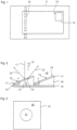
- the optically variable surface pattern 10 according to the invention is integrated as a security element in a banknote 11 in such a way that in 1 front of the banknote shown is visible.
- the optically variable element 10 according to the invention can be present, for example, as a window thread 12 .
- the optically variable element 10 has a rectangular surface area 13 with a multiplicity of micromirrors 14, which are formed on a reflection layer 15, as in particular the enlarged sectional view of two micromirrors 14 in 2 can be seen.
- the micromirrors 14 are formed by an embossed lacquer layer 16, whose side facing away from the reflection layer 15 is structured (here with a sawtooth profile), and a coating 17 which is provided on the structured side of the embossed lacquer layer 16. As the representation of 2 it can be seen that the micromirrors 14 are inclined relative to the reflection layer 15 (angle ⁇ ).
- the coating 17 can, but need not, be provided.
- the coating 17 is designed as a partially reflective coating which specularly reflects part of an incident light beam L1 and thus generates a first reflected light beam L2 and which transmits another part of the incident light beam L1.
- the transmitted part runs through the embossing lacquer layer 16 (light beam L4), hits the reflection layer 15 and is reflected by it (light beam L5), again runs through the embossing lacquer layer 16 and the coating 17 and exits as a second reflected light beam L3.
- the refraction occurring at the interfaces between the different media is in 2 only shown schematically. Refraction takes place at the transition between the environment and the coating 17 and at the interface between the coating 17 and the embossing lacquer layer 16 . Furthermore, multiple reflections that can occur as a result of renewed reflection of the light beam L5 to the reflection layer 15 are not taken into account.
- an incident light beam L1 on the coating 17 or on the micromirror 14 is specular in a first direction (first reflected light beam L2) and by refraction at the interface between the environment and the coating 17 on the one hand and the interface between the coating layer 17 and the stamping varnish layer 16 on the other hand, and reflection at the reflection layer 15 in a second direction (second reflected light beam L3), the two directions being different.
- the brightness and color of the first reflected light beam L2 can be specified by the optical properties of the coating 17 .
- the brightness and color of the second reflected light beam L3 can be specified by the optical properties of the reflection layer 15, for example.
- the embossing lacquer layer 16 it is possible for the embossing lacquer layer 16 to be colored, which influences the color and brightness of the second reflected light beam L2.
- the different colors can be seen, for example, with a relatively small gradient of the micromirrors 14 under very close viewing angles become visible. Very discrete, ie fast and clear, color changes are thus possible, which clearly stand out from the continuous and rather slow color changes, for example of a thin-layer color shift coating with absorber/dielectric/reflector.
- the coating 17 can also be referred to as an anti-reflective coating since it increases the reflectance of the micromirrors 14 compared to the case without the coating 17 .
- the side of the reflective layer 15 facing the micromirrors 14 is preferably flat.
- the reflection layer 15 can be designed, for example, as a metallic coating (e.g. Ag, Al, Cu, . . . ) or as a color-shifting coating, in particular as a thin-layer system.
- the thin-layer system can have an absorber/dielectric/reflector structure, for example.
- the structuring of the side of the embossing lacquer layer 16 facing away from the reflection layer 5 is preferably produced by an embossing process.
- the structured embossing lacquer layer 16 (together with the optionally provided coating 17) thus serves according to the invention as a mirror (for the first reflected light beam L2) and as a prism (for the second reflected light beam L3).
- the material of the embossing lacquer layer 16 and/or the coating 17 is selected such that the refractive index of this material differs from the refractive index of the medium 18 (here eg air) adjoining the embossing lacquer layer 16 or the coating 17.
- the refractive index of the embossing lacquer layer is different 16 or the coating 17 is greater than that of the medium 18.
- a protective lacquer layer can also be provided (not shown).
- the refractive indices of the embossing lacquer layer 16 or of the coating 17 and of the medium 18 can be selected such that when light L1 is incident perpendicularly (relative to the reflection layer 15), the two reflected light beams L2 and L3 are on the same side of the macroscopic normal N of the optically variable surface pattern 10 ( 2 ) are reflected, but at different angles.
- This can be used, for example, to create two-color running effects that do not run in opposite directions but in the same direction, but at different speeds.
- a "rolling bar" can be created in which two differently colored bars run in the same direction at different speeds.
- the micromirrors 14 thus form a micromirror array or a micromirror arrangement 19, which performs the specular reflection of the first reflected light beam L2 and enables the reflection of the transmitted part of the incident light beam L1 on the reflection layer 15, so that the second reflected light beam L3 is generated.
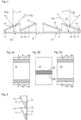
- the optically variable surface pattern 10 can, for example, have a first and a second region 21, 22, as shown in a schematic top view in 3 is indicated, have, in which the inclinations (angle ⁇ ) of the micromirror 14 of the micromirror array 19 differ.
- the inclinations can be chosen such that the direction of the first reflected light beam L2 21 from the first area 21 coincides with the direction of the second reflected light beam L3 22 from the second area 22, however, the colors of these two light rays are different.
- a corresponding sectional view of micromirrors 14 from areas 21 and 22 is shown in FIG 4 shown. Thus, the two colors are visible to the viewer from the same viewing angle. These colors can thus be presented to the viewer with extremely high resolution and perfectly registered next to one another.
- the second reflected light beam L3 21 from the first area 21 and the first reflected light beam L2 22 from the second area have different directions here.
- the so-called “rolling bar” effect can be produced with the optically variable surface pattern according to the invention.
- the reflection layer 15 can be designed as a color shift coating and the coating 17 as a layer with a high refractive index, so that with appropriately selected layer thicknesses the first reflected light beam L2 appears green and the second reflected light beam L3 appears magenta.
- magenta bar B1 is hatched horizontally and the green bar B2 is hatched vertically. In a basic position, both bars B1, B2 overlap in the middle of the optically variable surface pattern 10, with in Figure 5B , which shows this basic position, no exact superimposition is drawn for clarification.
- magenta bar B1 when tilted in a first direction, the magenta bar B1 may move up and the green bar B2 move down, as in FIG Figure 5C is indicated by the drawn arrows P1 and P2.
- the two bars move in the opposite direction, ie the magenta bar B1 down and the green bar B2 up ( Figure 5A ), whereby the directions of movement are again indicated by the arrows P1 and P2.
- the inclination ⁇ of the micromirrors 14 can be varied in the desired direction of movement, for example, as shown schematically in the sectional view in FIG 6 is shown, which according to a section in the direction of arrow P1 Figure 5A of two adjacent micromirrors 14 shows.
- the angles of inclination ⁇ 1 and ⁇ 2 shown differ, with the angle of inclination ⁇ increasing from bottom to top.
- the "rolling bar” effect described is an example of a two-tone overlapping rolling effect that can be realized with the optical surface pattern according to the invention.
- other running effects can also be implemented.
- so-called flip, running and/or pumping effects can be realized when tilting the optically variable surface pattern, which can be in the same direction or in opposite directions.
- a pumping effect can also be realized in which the outline of a symbol or a denomination "pumps" inwards or outwards. Repeating pumping effects with many simultaneously visible outlines, which can then light up very delicately in different colors when viewed from the right angle, are particularly attractive.
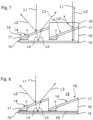
- the micromirror array 14 can be partially embedded in a medium 18 that has a similar refractive index as the embossing lacquer layer 16 or the coating 17, as in FIG 7 is shown.
- the refraction at the top of the relief structure is thus locally eliminated, as a result of which the directions of the first and second reflected light beams L2' and L3' from areas with medium 18 differ from the directions of the first and second light beams L2, L3 from areas without medium 18. This is due in particular to the fact that the medium 18 cancels out the refraction effects for the second reflected light beam L3' and for the first reflected light beam Added refraction effects to Light Ray L2'.
- the first reflected light ray L2' is also refracted at the top of the layer 18 and thus travels in a generally different direction than the first light ray L2 from the area without coating 18.
- the second Light beam L3' from the area with coating 18 can always be seen in the specular reflection of reflection layer 15 and thus runs in a different direction than the second light beam L3 from the area without coating 18.
- the optically variable surface pattern 10 can be formed, for example, in such a way that the first reflected light beam L2 is green and the refracted and downwardly reflected second light beam L3 is magenta. If you then choose the slopes of the micro-mirrors 14 so that they are in the areas 21 and 22 according to 3 are the same and in the area 22 the refraction-eliminating coating 18 is provided on the upper side of the optically variable surface pattern 10, the following optical effects are achieved. Region 22 is brightly visible at two different first angles. It is visible in green through the light rays L2' and in magenta through the light rays L3'.
- Area 21 is visible from two other angles in green (through light rays L2) and in magenta (light rays L3). Since the coating 18 has a similar or ideally the same refractive index as the coating 17, there is also the special feature here that the direction of reflection of the second light beam L3' always corresponds to a specular reflection on the reflection layer 15 (regardless of the inclination ⁇ of the micromirror 14). The area 22 thus lights up in the specular reflection of the reflection layer 15, ie always as a homogeneous magenta-colored area, even if the micromirrors 14 have a varying orientation in this area, for example.
- the structuring of the side of the embossing lacquer layer 16 facing away from the reflection layer 15 for forming the micromirrors 14 can be regular or irregular. In particular, periodic or aperiodic sawtooth structures are possible.
- embossing lacquer layer 16 no coating 17 may be provided on the embossing lacquer layer 16 .
- the embossing lacquer of the embossing lacquer layer 16 can preferably be a high-index embossing lacquer.
- the layer 16 does not have to be an embossing lacquer layer, but can also be any other transparent or partially transparent layer with a structured upper side or with a relief structure on the upper side.
- the coating 17 can be a dielectric coating, in particular a high-index coating or a low-index coating on high-index embossing varnish 16.
- a multi-layer thin-film system metal/dielectric/metal
- a purely dielectric multi-layer system is also possible.
- the coating 17 can be in the form of a liquid crystal layer.
- a configuration of the surface of the micromirrors 14 with colored embossed structures and/or nanostructures is also possible (e.g. semitransparent metallized sub-wavelength structures, in particular sub-wavelength gratings).
- the reflective layer 15 can, for example, be in the form of a liquid crystal layer (advantageously against a dark background). It is also possible to provide color-generating nanostructures (eg sub-wavelength structures, in particular sub-wavelength gratings), photonic crystals, thin-film color shift or a simple metallization (eg Al, Au, Cu, Cr, ).
- the reflection layer 15 can be partially transparent, so that the optically variable surface pattern 10 according to the invention can also have an optically variable effect visible from the underside (through transmission through the reflection layer 15, reflection at the micromirrors 14 and renewed transmission through the partially transparent lower reflection layer 15 back to the Back).
- the optically variable surface pattern 10 according to the invention can in particular be designed in such a way that the two reflected light beams L2 and L3 (in particular approximately) appear equally bright and/or have a different color (in particular complementary colors).
- the coating 17 can be particularly reflective of a first color while allowing the complementary color to pass through to a large extent. The complementary color is then reflected on the reflection layer 15.
- dielectric layers, multilayers or liquid crystal layers are particularly suitable for the coating 17, in which case the incident light can be split into reflected and transmitted light largely without loss of absorption.
- the optically variable surface pattern 10 can be formed in such a way that one of the two reflected light beams L2, L3 appears colorless (white), white also being referred to as color in the sense of the present invention.
- the micromirrors 14 can be embedded, for example (eg the embossing lacquer layer 16 can have a greater refractive index than the layer to be provided for embedding, which can be a protective lacquer layer, for example).
- the embedding layer it is also possible for the embedding layer to have a greater refractive index than the embossing lacquer layer 16.
- a protective film can be provided, which is selected in such a way that the refractive effect of the micromirrors 14 is retained and is not destroyed, for example, by a laminating adhesive with a similar refractive index.
- the protective film can be spot-welded (e.g. with a laser), glued on, etc., in order to keep air or gas pockets. It is also possible to use a high-index embossing varnish or, for example, to leave out the laminating adhesive for the protective film in the area of the optically variable surface pattern.
- the optically variable surface pattern according to the invention is preferably produced and/or used on a carrier film.
- the carrier film can be arranged in particular under the reflection layer 15, between the reflection layer 15 and the embossing lacquer layer 16 or the micromirrors 14 or also above the micromirrors 14.
- the reflective layer 15 and the coating 17 can be cut out in certain areas, e.g. in the same or different, overlapping or non-overlapping areas. The corresponding colors or effects are then only visible in certain areas.
- the micromirrors 14 can advantageously be embossed in a colored embossing lacquer 16 . Colors of the second light beam L3 that is refracted and reflected from below can thus be produced comparatively inexpensively.
- a separate colored layer 23 e.g. lacquer layer
- lacquer layer can also be provided between the micromirrors 14 made of transparent embossing lacquer and the reflection layer 15, for example, as shown in FIG 8 is shown.
- the optically variable surface pattern 10 according to the invention can also be used as a security thread 12 ( figure 1 ) be trained. Furthermore, the optically variable Areal patterns 10 are not only, as described, formed on a carrier film from which it can be transferred in a known manner to the document of value. In an embodiment not covered by the claims, it is also possible to form the optically variable surface pattern 10 directly on the document of value. Direct printing with subsequent embossing of the micromirrors on a polymer substrate can thus be carried out in order to form an optically variable surface pattern according to the invention, for example in the case of plastic banknotes.
- the optically variable surface pattern according to the invention can be formed in a wide variety of substrates.
- a paper with synthetic fibers ie paper with a proportion x of polymeric material in the range of 0 ⁇ x ⁇ 100% by weight
- a plastic film e.g. B. a film made of polyethylene (PE), polyethylene terephthalate (PET), polybutylene terephthalate (PBT), polyethylene naphthalate (PEN), polypropylene (PP) or polyamide (PA), or a multilayer composite, in particular a composite of several different films (composite composite) or a paper-foil composite (foil/paper/foil or paper/foil/paper), wherein the optically variable surface pattern may be provided in or on or between any of the layers of such a multi-layer composite.
- PE polyethylene
- PET polyethylene terephthalate
- PBT polybutylene terephthalate
- PEN polyethylene naphthalate
- PP polypropylene
- PA polyamide
- a multilayer composite in particular a composite of several different films (compo
Description
Die Erfindung betrifft ein optisch variables Flächenmuster sowie ein Wertdokument mit einem solchen optisch variablen Flächenmuster.The invention relates to an optically variable surface pattern and a document of value with such an optically variable surface pattern.
Zu schützende Gegenstände werden häufig mit einem optisch variablen Flächenmuster ausgestattet, das die Überprüfung der Echtheit des Gegenstandes erlaubt und zugleich als Schutz vor unerlaubter Reproduktion dient.Objects to be protected are often equipped with an optically variable surface pattern that allows the authenticity of the object to be checked and at the same time serves as protection against unauthorized reproduction.
Bekannt sind diffraktive Reliefstrukturen (Hologramme) sowie strahlenoptisch wirksame Reliefstrukturen (Mikrospiegel bzw. -prismen).Diffractive relief structures (holograms) and radiation-optically effective relief structures (micromirrors or prisms) are known.
Diffraktive Reliefstrukturen erzeugen durch Beugung Farben, wobei in der Regel beim Kippen das ganze Farbspektrum durchlaufen wird oder durch Farbmischung beispielsweise bei Mattstrukturen ein weißer Farbeindruck erzeugt wird.Diffractive relief structures produce colors through diffraction, with the entire color spectrum usually being run through when tilted, or a white color impression being produced through color mixing, for example in the case of matt structures.
Strahlenoptisch wirksame Reliefstrukturen liefern von sich aus zunächst farblose Darstellungen. Durch das Vorsehen einer zusätzlichen Farbbeschichtung (beispielsweise einer Farbkipp- bzw. Colorshift-Beschichtung) können Farben oder auch Farbwechsel erzeugt werden. Solche Beschichtungen liefern unter einem bestimmten Betrachtungswinkel bzw. Glanzwinkel der Mikrospiegel in der Regel nur eine Farbe bzw. einen durch die Beschichtung definiert eingestellten Farbumschlag.Radiation-optically effective relief structures initially provide colorless representations of their own accord. By providing an additional color coating (for example a color tilt or color shift coating), colors or also color changes can be produced. At a specific viewing angle or glancing angle of the micromirrors, such coatings generally only produce one color or a color change set in a defined manner by the coating.
Ausgehend hiervon ist es Aufgabe der Erfindung, ein optisch variables Flächenmuster bereitzustellen, mit dem verschiedene optische Effekte realisiert werden können.Proceeding from this, it is the object of the invention to provide an optically variable surface pattern with which various optical effects can be realized.
Aus der Druckschrift
Die Druckschrift
Die Druckschrift
In der Druckschrift
Erfindungsgemäß wird die Aufgabe durch ein optisch variables Flächenmuster mit den Merkmalen von Anspruch 1 gelöst.According to the invention, the object is achieved by an optically variable surface pattern having the features of claim 1.
Damit stellt das erfindungsgemäße optisch variable Flächenmuster zwei reflektierte Lichtstrahlen, die in unterschiedlichen Richtungen reflektiert werden, zur Verfügung, mit denen Farbeffekte und/oder Bewegungseffekte verwirklicht werden können.The optically variable surface pattern according to the invention thus provides two reflected light beams, which are reflected in different directions, with which color effects and/or movement effects can be implemented.
Bei dem erfindungsgemäßen optisch variablen Flächenmuster ist eine transparente oder teiltransparente Schicht auf der Reflexionsschicht ausgebildet, wobei zur Ausbildung der Mikrospiegel die von der Reflexionsschicht abgewandte Seite der transparenten oder teiltransparenten Schicht in einem vorbestimmten Bereich strukturiert ist. Im vorbestimmten Bereich ist eine teilreflektive Beschichtung ausgebildet. Die teilreflektive Beschichtung kann auch als reflexionserhöhende Beschichtung bezeichnet werden.In the optically variable surface pattern according to the invention, a transparent or partially transparent layer is formed on the reflection layer, the side of the transparent or partially transparent layer facing away from the reflection layer being structured in a predetermined area to form the micromirrors. A partially reflective coating is formed in the predetermined area. The partially reflective coating can also be referred to as a reflection-increasing coating.
Die Strukturierung und/ oder die teilreflektive Beschichtung können insbesondere so ausgebildet sein, dass eine (im Wesentlichen) strahlenoptisch wirksame Reliefstruktur (und keine Beugungsstruktur) vorliegt, die die Reflexion des einfallenden Lichtes in die erste Richtung bewirkt.The structuring and/or the partially reflective coating can in particular be designed in such a way that a (substantially) optically radiation effective relief structure (and no diffraction structure) is present, which causes the reflection of the incident light in the first direction.
Eine reflexionserhöhende Beschichtung im Sinne der vorliegenden Erfindung ist insbesondere eine Beschichtung, die den Reflexionsgrad beispielsweise nur von etwa 20% auf etwa 50% erhöht, wie z.B. semitransparente Schichten. Die reflexionserhöhende Beschichtung kann eine metallische Beschichtung sein, die beispielsweise aufgedampft ist. Als Beschichtungsmaterial kann insbesondere Aluminium, Gold, Silber, Kupfer, Palladium, Chrom, Nickel und/ oder Wolfram sowie deren Legierungen verwendet werden. Alternativ kann die reflexionserhöhende Beschichtung durch eine Beschichtung mit einem Material mit hohem Brechungsindex gebildet werden. Die teilreflektive Beschichtung und/ oder die Reflexionsschicht können in Form von Mustern, Zeichen oder Codierungen vorliegen und/ oder Aussparungen in Form von Mustern, Zeichen oder Codierungen aufweisen.A reflection-enhancing coating within the meaning of the present invention is in particular a coating that increases the degree of reflection, for example, only from about 20% to about 50%, such as semi-transparent layers. The reflection-increasing coating can be a metallic coating that is vapor-deposited, for example. In particular, aluminum, gold, silver, copper, palladium, chromium, nickel and/or tungsten and their alloys can be used as the coating material. Alternatively, the anti-reflective coating may be formed by a coating of a high refractive index material. The partially reflective coating and/or the reflective layer can be in the form of patterns, characters or codes and/or have gaps in the form of patterns, characters or codes.
Die teilreflektive Beschichtung kann eine farbkippende Schicht sein, die z.B. als Dünnschichtsystem oder Dünnfilm-Interferenzbeschichtung ausgebildet ist. Dies kann z.B. durch eine hochbrechende Schicht geeigneter Dicke (die Dicke ist bevorzugt so eingestellt, dass die gewünschte Farbe durch Interferenz der an der oberen und unteren Grenzfläche reflektierten Lichtstrahlen entsteht), eine Schichtfolge Metallschicht-dielektrische Schicht-Metallschicht oder eine Schichtfolge aus mindestens drei dielektrischen Schichten, wobei die Brechzahl der mittleren Schicht geringer ist als die Brechzahl der beiden anderen Schichten, verwirklicht werden. Die farbkippende Schicht kann auch als Interferenzfilter, dünne semitransparente Metallschicht mit selektiver Transmission durch Plasmaresonanzeffekte, Nanopartikel, etc. ausgebildet sein. Die farbkippende Schicht kann insbesondere auch als Flüssigkristallschicht, diffraktive Reliefstruktur oder Subwellenlängengitter realisiert sein.The partially reflective coating can be a color-shifting layer that is designed, for example, as a thin-layer system or thin-film interference coating. This can be done, for example, by a high-index layer of suitable thickness (the thickness is preferably set such that the desired color is produced by interference of the light beams reflected at the upper and lower interfaces), a metal layer-dielectric layer-metal layer sequence or a layer sequence of at least three dielectrics Layers in which the refractive index of the middle layer is lower than the refractive index of the other two layers can be realized. The color-shifting layer can also be in the form of an interference filter, a thin, semi-transparent metal layer with selective transmission through plasma resonance effects, nanoparticles, etc. The color-shifting layer can, in particular, also be used as a liquid crystal layer, diffractive relief structure or sub-wavelength grating can be realized.
Die Mikrospiegel bzw. die teilreflektiven Flächen der Mikrospiegel, die die Reflexion des einfallenden Lichtes in die erste Richtung bewirken, sind bevorzugt eben ausgebildet. Die ebene Ausbildung der teilreflektiven Flächen ist natürlich nicht im mathematisch exakten Sinne zu verstehen, da sich in der Praxis herstellungsbedingt in der Regel nie perfekt ebene Flächenstücke herstellen lassen. Die ebene Ausbildung ist daher bevorzugt so zu verstehen, dass es insoweit eben ist, als es herstellungstechnisch möglich ist. Alternativ ist es möglich, die teilreflektiven Flächen der Mikrospiegel gekrümmt auszubilden (z.B. konkav, konvex oder gewellt). Jedoch ist die Krümmung der teilreflektiven Flächen der Mikrospiegel bevorzugt gering.The micromirrors or the partially reflective surfaces of the micromirrors, which bring about the reflection of the incident light in the first direction, are preferably flat. The planar formation of the partially reflective surfaces is, of course, not to be understood in the mathematically exact sense, since in practice it is generally never possible to produce perfectly planar surface sections due to the production process. The planar design is therefore preferably to be understood in such a way that it is planar to the extent that it is technically possible in terms of production. Alternatively, it is possible to design the partially reflective surfaces of the micromirrors to be curved (e.g. concave, convex or wavy). However, the curvature of the partially reflective surfaces of the micromirrors is preferably small.
Die teiltransparente Schicht kann z.B. als gefärbte Schicht oder als Farbschicht ausgebildet sein. Damit kann die Farbe des in der zweiten Richtung reflektierten Lichtes beeinflusst oder eingestellt werden.The partially transparent layer can be formed, for example, as a colored layer or as a colored layer. The color of the light reflected in the second direction can thus be influenced or adjusted.
Bei der transparenten oder teiltransparenten Schicht kann es sich um eine Lackschicht und insbesondere um eine Prägelackschicht handeln.The transparent or partially transparent layer can be a lacquer layer and in particular an embossing lacquer layer.
Ferner kann die Strukturierung der transparenten oder teiltransparenten Schicht durch Prägen gebildet sein.Furthermore, the structuring of the transparent or partially transparent layer can be formed by embossing.
Des Weiteren kann zwischen der Reflexionsschicht und der transparenten oder teiltransparenten Schicht eine teiltransparente Farbschicht angeordnet sein. Mit der teiltransparenten Farbschicht kann die Farbe des in der zweiten Richtung reflektierten Lichtes beeinflusst oder eingestellt werden.Furthermore, a partially transparent colored layer can be arranged between the reflection layer and the transparent or partially transparent layer. The color of the light reflected in the second direction can be influenced or adjusted with the partially transparent color layer.
Die transparente oder teiltransparente Schicht und/ oder die teilreflektive Beschichtung kann zumindest in einem Teil des sichtbaren Spektrums einen Brechungsindex von mindestens 1,6 und bevorzugt von mindestens 1,8 aufweisen.The transparent or partially transparent layer and/or the partially reflective coating can have a refractive index of at least 1.6 and preferably at least 1.8 in at least part of the visible spectrum.
Ferner können die Mikrospiegel in ein Medium eingebettet sein, das zumindest in einem Teil des sichtbaren Spektrums einen Brechungsindex aufweist, der von dem Brechungsindex der transparenten oder teiltransparenten Schicht und/oder der teilreflektiven Beschichtung um mindestens 0,1, bevorzugt um mindestens 0,2 und besonders bevorzugt um mindestens 0,4 abweicht. Diese Einbettungsschicht kann Bestandteil des optisch variablen Flächenmusters sein. Es ist jedoch auch möglich, dass es sich dabei um das angrenzende Medium (z.B. Luft handelt).Furthermore, the micromirrors can be embedded in a medium that has a refractive index in at least part of the visible spectrum that differs from the refractive index of the transparent or partially transparent layer and/or the partially reflective coating by at least 0.1, preferably by at least 0.2 and more preferably deviates by at least 0.4. This embedding layer can be part of the optically variable surface pattern. However, it is also possible that this is the adjacent medium (e.g. air).
Bei dem optisch variablen Flächenmuster können die Reflexionsschicht und die Mikrospiegelanordnung so ausgebildet sein, dass das in die erste und zweite Richtung reflektierte Licht unterschiedliche Farben aufweist.In the case of the optically variable surface pattern, the reflective layer and the micromirror arrangement can be designed in such a way that the light reflected in the first and second direction has different colors.
Ferner können die teiltransparenten Mikrospiegel ein sägezahnförmiges Profil bilden. Die Anordnung der Mikrospiegel kann regelmäßig oder auch unregelmäßig sein.Furthermore, the partially transparent micromirrors can form a sawtooth-shaped profile. The arrangement of the micromirrors can be regular or irregular.
Insbesondere kann die den teiltransparenten Mikrospiegeln zugewandte Seite der Reflexionsschicht und/ oder die den Mikrospiegeln abgewandte Seite der Reflexionsschicht eben ausgebildet sein.In particular, the side of the reflection layer facing the partially transparent micromirrors and/or the side of the reflection layer facing away from the micromirrors can be flat.
Bei dem erfindungsgemäßen optisch variablen Flächenmuster können mehrere der Mikrospiegel in einer Anordnungsrichtung nebeneinander angeordnet sein und ihre Abmessung in der Anordnungsrichtung kann im Bereich von 2 µm bis 3mm, bevorzugt von 3 µm bis 100 µm und besonders bevorzugt von 5 µm bis 30 µm liegen.In the optically variable area pattern of the present invention, a plurality of the micromirrors may be arranged side by side in an arrangement direction, and their dimension in the arrangement direction may be in the range from 2 μm to 3 mm, preferably from 3 μm to 100 μm and particularly preferably from 5 μm to 30 μm.
Das optisch variable Flächenmuster kann so ausgebildet sein, dass bei parallel zur makroskopischen Oberflächennormalen des Flächenmusters einfallendem Licht die erste und zweite Richtung des reflektierten Lichtes auf unterschiedlichen Seiten der makroskopischen Oberflächennormalen liegen. Es ist jedoch auch möglich, dass die erste und zweite Richtung des reflektierten Lichtes auf der gleichen Seite der makroskopischen Oberflächennormalen liegen.The optically variable surface pattern can be designed in such a way that when light is incident parallel to the macroscopic surface normal of the surface pattern, the first and second directions of the reflected light lie on different sides of the macroscopic surface normal. However, it is also possible for the first and second direction of the reflected light to lie on the same side of the macroscopic normal to the surface.
Die teilreflektive Beschichtung kann eine oder mehrere (insbesondere hochbrechende) dielektrische Schicht bzw. Schichten, eine semitransparente metallische Schicht, eine Schicht aus halbleitendem Material und/oder eine flüssigkristalline Schicht aufweisen.The partially reflective coating can have one or more (in particular high-index) dielectric layer or layers, a semi-transparent metallic layer, a layer made of semiconducting material and/or a liquid-crystalline layer.
Ferner kann die Farberzeugung an der Reflexionsschicht und/oder an der Oberfläche der Mikrospiegel durch Subwellenlängenstrukturen, insbesondere Subwellenlängengitter, realisiert sein.Furthermore, the generation of color on the reflection layer and/or on the surface of the micromirrors can be realized by sub-wavelength structures, in particular sub-wavelength gratings.
Die Reflexionsschicht kann eine oder mehrere metallische Schichten, eine Dünnfilm-Colorshift-Schicht (insbesondere mit dem Aufbau Absorber/Dielektrikum/Reflektor oder dem Aufbau Absorber/ Dielektrikum/ Reflektor/Dielektrikum/Absorber), eine oder mehrere (insbesondere hochbrechende) dielektrische Schichten und/ oder eine flüssigkristalline Schicht aufweisen.The reflection layer can be one or more metallic layers, a thin-film color shift layer (in particular with the structure absorber/dielectric/reflector or the structure absorber/dielectric/reflector/dielectric/absorber), one or more (in particular high-index) dielectric layers and/or or have a liquid crystalline layer.
Als dielektrisches Material für die teilreflektive Beschichtung und die Reflexionsschicht kann z.B. ZnS, SiO2, TiO2, MgF2 verwendet werden.ZnS, SiO 2 , TiO 2 , MgF 2 , for example, can be used as the dielectric material for the partially reflective coating and the reflection layer.
Das erfindungsgemäße optisch variable Flächenmuster ist so ausgebildet, dass mit den in die erste Richtung reflektierten Lichtstrahlen (oder den in die zweite Richtung reflektierten Lichtstrahlen) unterschiedlichste Bewegungseffekte z.B. beim Kippen des Flächenmusters verwirklicht werden. So kann z.B. der in der
Ferner kann das erfindungsgemäße optisch variable Flächenmuster (einschließlich seiner Weiterbildungen) als Sicherheitselement, insbesondere als Sicherheitselement für Sicherheitspapiere, Wertdokumente oder dergleichen verwendet werden.Furthermore, the optically variable surface pattern according to the invention (including its developments) can be used as a security element, in particular as a security element for security papers, documents of value or the like.
Das Sicherheitselement kann insbesondere als Sicherheitsfaden, Aufreißfaden, Sicherheitsband, Sicherheitsstreifen, Patch, Folienelement oder als Etikett zum Aufbringen auf ein Sicherheitspapier, Wertdokument oder dergleichen ausgebildet sein. Insbesondere kann das Sicherheitselement transparente Bereiche oder Ausnehmungen überspannen. Ferner kann das Sicherheitselement bei Polymer- oder Hybridbanknoten unter Folie eingebettet sein.The security element can in particular be designed as a security thread, tear-open thread, security band, security strip, patch, film element or as a label for application to security paper, a document of value or the like. In particular, the security element can span transparent areas or recesses. Furthermore, in the case of polymer or hybrid banknotes, the security element can be embedded under foil.
Unter dem Begriff Sicherheitspapier wird hier insbesondere die noch nicht umlauffähige Vorstufe zu einem Wertsdokument verstanden, die neben dem erfindungsgemäßen Sicherheitselement beispielsweise auch weitere Echtheitsmerkmale (wie z.B. im Volumen vorgesehene Lumineszenzstoffe) aufweisen kann. Unter Wertdokumenten werden hier einerseits aus Sicherheitspapieren hergestellte Dokumente verstanden. Andererseits können Wertdokumente auch sonstige Dokumente und Gegenstände sein, die mit dem erfindungsgemäßen Sicherheitselement versehen werden können, damit die Wertdokumente nicht kopierbare Echtheitsmerkmale aufweisen, wodurch eine Echtheitsprüfung möglich ist und zugleich unerwünschtes Kopieren verhindert wird.The term security paper is understood here, in particular, as the precursor to a value document that is not yet fit for circulation security element according to the invention can, for example, also have other authenticity features (such as, for example, luminescent substances provided in the volume). Documents of value are understood here on the one hand as documents produced from security papers. On the other hand, documents of value can also be other documents and objects that can be provided with the security element according to the invention, so that the documents of value have authenticity features that cannot be copied, whereby an authenticity check is possible and at the same time undesired copying is prevented.
Ferner wird ein Wertdokument mit einem erfindungsgemäßen optisch variablen Flächenmuster (einschließlich seiner Weiterbildungen) bereitgestellt.Furthermore, a document of value with an optically variable surface pattern according to the invention (including its developments) is provided.
Es versteht sich, dass die vorstehend genannten und die nachstehend noch zu erläuternden Merkmale nicht nur in den angegebenen Kombinationen, sondern auch in anderen Kombinationen oder in Alleinstellung einsetzbar sind, ohne den Rahmen der vorliegenden Erfindung zu verlassen.It goes without saying that the features mentioned above and those still to be explained below can be used not only in the specified combinations, but also in other combinations or on their own, without departing from the scope of the present invention.
Nachfolgend wird die Erfindung beispielshalber anhand der beigefügten Figuren, die auch erfindungswesentliche Merkmale offenbaren, noch näher erläutert. Zur besseren Anschaulichkeit wird in den Figuren teilweise auf eine maßstabs- und proportionsgetreue Darstellung verzichtet. Es zeigen:
- Figur 1
- eine Draufsicht einer Banknote mit einem erfindungsgemäßen optisch variablen Flächenelement 10;
- Figur 2
- eine vergrößerte Schnittansicht zweier Mikrospiegel des optisch variablen Flächenelementes von
Figur 1 ; - Figur 3
- eine Draufsicht einer weiteren Ausführungsform eines rechteckigen Flächenbereichs 13 des erfindungsgemäßen optisch variablen Elementes 10;
- Figur 4
- eine vergrößerte Schnittansicht von jeweils zwei Mikrospiegeln 14 aus den beiden
Bereichen 21 und 22 gemäßFigur 3 ; - Figuren 5A-5C
- Darstellungen zur Erläuterung des "Rolling Bar"-Effektes;
- Figur 6
- eine vergrößerte Schnittansicht zweier Mikrospiegel 14 zur Erläuterung des in Verbindung mit
Figuren 5A-5C beschriebenen "Rolling Bar"-Effektes; - Figur 7
- eine vergrößerte Schnittansicht zweier Mikrospiegel 14 einer weiteren Ausführungsform des erfindungsgemäßen optisch variablen Flächenmusters, und
- Figur 8
- eine vergrößerte Schnittansicht zweier Mikrospiegel 14 einer weiteren Ausführungsform des erfindungsgemäßen optisch variablen Flächenmusters 10.
- figure 1
- a plan view of a bank note with an optically
variable surface element 10 according to the invention; - figure 2
- an enlarged sectional view of two micromirrors of the optically variable surface element of FIG
figure 1 ; - figure 3
- a plan view of a further embodiment of a
rectangular surface area 13 of the opticallyvariable element 10 according to the invention; - figure 4
- an enlarged sectional view of two
micromirrors 14 from the twoareas figure 3 ; - Figures 5A-5C
- Representations to explain the "rolling bar"effect;
- figure 6
- an enlarged sectional view of two
micromirrors 14 to explain the in connection withFigures 5A-5C described "rolling bar"effect; - figure 7
- an enlarged sectional view of two
micromirrors 14 of a further embodiment of the optically variable surface pattern according to the invention, and - figure 8
- an enlarged sectional view of two
micromirrors 14 of a further embodiment of the opticallyvariable surface pattern 10 according to the invention.
Bei der in
Das optisch variable Element 10 weist in der hier beschriebenen Ausführungsform einen rechteckigen Flächenbereich 13 mit einer Vielzahl von Mikrospiegeln 14 auf, die auf einer Reflexionsschicht 15 gebildet sind, wie insbesondere der vergrößerten Schnittansicht zweier Mikrospiegel 14 in
Die Mikrospiegel 14 sind durch eine Prägelackschicht 16, deren der Reflexionsschicht 15 abgewandte Seite strukturiert ist (hier mit einem Sägezahnprofil), und einer Beschichtung 17, die auf der strukturierten Seite der Prägelackschicht 16 vorgesehen ist, gebildet. Wie der Darstellung der
Die Beschichtung 17 kann, muss aber nicht vorgesehen sein. Insbesondere ist die Beschichtung 17 als teilreflektive Beschichtung ausgebildet, die von einem einfallenden Lichtstrahl L1 einen Teil spekular reflektiert und somit einen ersten reflektierten Lichtstrahl L2 erzeugt und die einen anderen Teil des einfallenden Lichtstrahls L1 transmittiert.The
Der transmittierte Teil läuft durch die Prägelackschicht 16 (Lichtstrahl L4), trifft auf die Reflexionsschicht 15 und wird von dieser reflektiert (Lichtstrahl L5), läuft wiederum durch die Prägelackschicht 16 und die Beschichtung 17 und tritt als zweiter reflektierter Lichtstrahl L3 aus. Die an den Grenzflächen zwischen den verschiedenen Medien auftretende Brechung ist in
Wie der Darstellung gemäß
Die Helligkeit und Farbe des ersten reflektierten Lichtstrahls L2 können dabei durch die optischen Eigenschaften der Beschichtung 17 vorgegeben werden. Die Helligkeit und Farbe des zweiten reflektierten Lichtstrahls L3 können z.B. durch die optischen Eigenschaften der Reflexionsschicht 15 vorgegeben werden. Des Weiteren ist es möglich, die Prägelackschicht 16 farbig auszubilden, was die Farbe und Helligkeit des zweiten reflektierten Lichtstrahls L2 beeinflusst.In this case, the brightness and color of the first reflected light beam L2 can be specified by the optical properties of the
Es ist somit möglich, die Farbe der beiden reflektierten Lichtstrahlen L2 und L3 unterschiedlich einzustellen, so dass ein Betrachter unter einem bestimmten Betrachtungswinkel bei Betrachtung des optisch variablen Flächenmusters 10 die Farbe des ersten reflektierten Lichtstrahls L2 wahrnehmen kann und unter einem zweiten Winkel die Farbe des zweiten reflektierten Lichtstrahls L3 wahrnehmen kann. Für den Betrachter wird somit ein Farb-Flip-Effekt bereitgestellt.It is thus possible to set the color of the two reflected light beams L2 and L3 differently, so that an observer can perceive the color of the first reflected light beam L2 at a specific viewing angle when looking at the optically
Die verschiedenen Farben können z.B. bei relativ geringer Steigung der Mikrospiegel 14 unter sehr dicht beieinanderliegenden Betrachtungswinkeln sichtbar werden. Damit sind sehr diskrete, d.h. schnelle und deutliche Farbwechsel möglich, die sich von den kontinuierlichen und eher langsamen Farbwechseln beispielsweise einer Dünnschicht-Colorshift-Beschichtung mit Absorber/ Dielektrikum/ Reflektor deutlich abheben.The different colors can be seen, for example, with a relatively small gradient of the
Die Beschichtung 17 kann auch als reflexionserhöhende Beschichtung bezeichnet werden, da sie den Reflexionsgrad der Mikrospiegel 14 im Vergleich zu dem Fall ohne Beschichtung 17 erhöht.The
Die den Mikrospiegeln 14 zugewandte Seite der Reflexionsschicht 15 ist bevorzugt eben ausgebildet. Des Weiteren kann die Reflexionsschicht 15 beispielsweise als metallische Beschichtung (z.B. Ag, Al, Cu, ...) oder als farbkippende Beschichtung, insbesondere als Dünnschichtsystem ausgebildet sein. Das Dünnschichtsystem kann z.B. einen Absorber/Dielektrikum/Reflektor-Aufbau aufweisen.The side of the
Die Strukturierung der der Reflexionsschicht 5 abgewandten Seite der Prägelackschicht 16 ist bevorzugt durch einen Prägevorgang erzeugt. Die strukturierte Prägelackschicht 16 (zusammen mit der optional vorgesehenen Beschichtung 17) dient somit erfindungsgemäß gleichzeitig als Spiegel (für den ersten reflektierten Lichtstrahl L2) und als Prisma (für den zweiten reflektierten Lichtstrahl L3).The structuring of the side of the
Das Material der Prägelackschicht 16 und/oder der Beschichtung 17 ist so gewählt, dass sich die Brechzahl dieses Materials von der Brechzahl des an die Prägelackschicht 16 bzw. die Beschichtung 17 angrenzenden Mediums 18 (hier z.B. Luft) unterscheidet, Insbesondere ist die Brechzahl der Prägelackschicht 16 bzw. der Beschichtung 17 größer als die des Mediums 18. Als Medium 18 kann z.B. auch eine Schutzlackschicht vorgesehen sein (nicht eingezeichnet).The material of the
Insbesondere können die Brechungsindizes der Prägelackschicht 16 bzw. der Beschichtung 17 sowie des Mediums 18 so gewählt sein, dass bei senkrecht einfallendem Licht L1 (bezogen auf die Reflexionsschicht 15), die beiden reflektierten Lichtstrahlen L2 und L3 auf die gleiche Seite der makroskopischen Normalen N des optisch variablen Flächenmusters 10 (
Bei dem erfindungsgemäßen optisch variablen Flächenmuster 10 bilden somit die Mikrospiegel 14 ein Mikrospiegelarray bzw. eine Mikrospiegelanordnung 19, das/die die spekulare Reflexion des ersten reflektierten Lichtstrahls L2 durchführt und die Reflexion des transmittierten Teils des einfallenden Lichtstrahls L1 an der Reflexionsschicht 15 ermöglicht, so dass der zweite reflektierte Lichtstrahl L3 erzeugt wird.In the case of the optically
Das optisch variable Flächenmuster 10 kann z.B. einen ersten und einen zweiten Bereich 21, 22, wie in einer schematischen Draufsicht in
In einer weiteren Ausbildung kann mit dem erfindungsgemäßen optisch variablen Flächenmuster der sogenannte "Rolling Bar"-Effekt erzeugt werden. Dazu kann z.B. die Reflexionsschicht 15 als Colorshift-Beschichtung und die Beschichtung 17 als Schicht mit hoher Brechzahl ausgebildet sein, so dass bei entsprechend gewählten Schichtdicken der erste reflektierte Lichtstrahl L2 grün erscheint und der zweite reflektierte Lichtstrahl L3 magenta erscheint. In den Darstellungen in
Um diesen Bewegungseffekt zu erreichen, kann z.B. die Neigung α der Mikrospiegel 14 in der gewünschten Bewegungsrichtung variiert werden, wie schematisch in der Schnittansicht in
Der beschriebene "Rolling Bar"-Effekt ist ein Beispiel eines zweifarbigen überlappenden Laufeffektes, der mit dem erfindungsgemäßen optischen Flächenmuster verwirklicht werden kann. Es sind natürlich auch andere Laufeffekte realisierbar. So können insbesondere sogenannte Flip-, Lauf- und/oder Pumpeffekte beim Verkippen des optisch variablen Flächenmusters realisiert werden, die gleich- oder gegenläufig sein können.The "rolling bar" effect described is an example of a two-tone overlapping rolling effect that can be realized with the optical surface pattern according to the invention. Of course, other running effects can also be implemented. In particular, so-called flip, running and/or pumping effects can be realized when tilting the optically variable surface pattern, which can be in the same direction or in opposite directions.
Ferner kann auch ein Pumpeffekt realisiert werden, bei dem die Umrisse eines Symbols oder einer Wertzahl nach innen oder außen "pumpen". Besonders attraktiv sind hier wiederholende Pumpeffekte mit vielen gleichzeitig sichtbaren Umrisslinien, die unter dem richtigen Betrachtungswinkel dann sehr filigran in unterschiedlichen Farben aufleuchten können.Furthermore, a pumping effect can also be realized in which the outline of a symbol or a denomination "pumps" inwards or outwards. Repeating pumping effects with many simultaneously visible outlines, which can then light up very delicately in different colors when viewed from the right angle, are particularly attractive.
Das Mikrospiegelarray 14 kann bereichsweise in einem Medium 18 eingebettet sein, das einen ähnlichen Brechungsindex wie die Prägelackschicht 16 bzw. die Beschichtung 17 aufweist, wie in
Ferner kann das optisch variable Flächenmuster 10 z.B. so ausgebildet sein, dass der erste reflektierte Lichtstrahl L2 grün und der gebrochene und unten reflektierte zweite Lichtstrahl L3 magenta ist. Wenn man dann die Steigungen der Mikrospiegel 14 so wählt, dass sie in den Bereichen 21 und 22 gemäß
Die Strukturierung der der Reflexionsschicht 15 abgewandten Seite der Prägelackschicht 16 zur Ausbildung der Mikrospiegel 14 kann regelmäßig oder unregelmäßig sein. Insbesondere sind periodische oder aperiodische Sägezahnstrukturen möglich.The structuring of the side of the
Auf der Prägelackschicht 16 kann z.B. keine Beschichtung 17 vorgesehen sein. In diesem Fall liegt eine Grenzfläche der Prägelackschicht 16 zu Luft vor. Der Prägelack der Prägelackschicht 16 kann bevorzugt ein hochbrechender Prägelack sein. Natürlich muß die Schicht 16 keine Prägelackschicht sein, sondern kann auch jede andere transparente oder teiltransparente Schicht mit einer strukturierten Oberseite bzw. mit einer Reliefstruktur an der Oberseite sein.For example, no
Die Beschichtung 17 kann eine dielektrische Beschichtung sein, insbesondere eine hochbrechende Beschichtung oder eine niedrigbrechende Beschichtung auf hochbrechendem Prägelack 16. Auch ist ein mehrschichtiges Dünnfilmsystem (Metall/Dielektrikum/Metall) oder auch ein rein dielektrisches Mehrschichtsystem möglich. Des Weiteren kann die Beschichtung 17 als Flüssigkristallschicht ausgebildet sein. Eine Ausgestaltung der Oberfläche der Mikrospiegel 14 mit farbgebenden Prägestrukturen und/oder Nanostrukturen ist ebenfalls möglich (z.B. semitransparent metallisierte Subwellenlängenstrukturen, insbesondere Subwellenlängengitter).The
Die Reflexionsschicht 15 kann z.B. als Flüssigkristallschicht (vorteilhaft vor dunklem Hintergrund) ausgebildet sein. Es ist auch möglich, farberzeugende Nanostrukturen (z.B. Subwellenlängenstrukturen, insbesondere Subwellenlängengitter), photonische Kristalle, Dünnfilm-Colorshift oder eine einfache Metallisierung (z.B. Al, Au, Cu, Cr, ...) vorzusehen.The
Die Reflexionsschicht 15 kann teildurchlässig sein, so dass das erfindungsgemäße optisch variable Flächenmuster 10 auch einen von der Unterseite sichtbaren optischen variablen Effekt aufweisen kann (durch Transmission durch die Reflexionsschicht 15, Reflexion an den Mikrospiegeln 14 und erneute Transmission durch die teildurchlässige untere Reflexionsschicht 15 zurück zur Rückseite).The
Das erfindungsgemäße optisch variable Flächenmuster 10 kann insbesondere so ausgebildet sein, dass die beiden reflektierten Lichtstrahlen L2 und L3 (insbesondere etwa) gleich hell erscheinen und/oder eine unterschiedliche Farbe aufweisen (insbesondere Komplementärfarben). So kann z.B. die Beschichtung 17 eine erste Farbe besonders stark reflektieren und die Komplementärfarbe gleichzeitig in hohem Maß hindurchlassen. Die Komplementärfarbe wird dann an der Reflexionsschicht 15 reflektiert. In diesem Fall sind insbesondere für die Beschichtung 17 dielektrische Schichten, Multilagen oder Flüssigkristallschichten besonders geeignet, bei denen das einfallende Licht weitgehend ohne Absorptionsverlust in reflektiertes und transmittiertes Licht aufgespalten werden kann. Des Weiteren kann das optisch variable Flächenmuster 10 so ausgebildet werden, dass einer der beiden reflektierten Lichtstrahlen L2, L3 farblos (weiß) erscheint, wobei weiß im Sinne der vorliegenden Erfindung auch als Farbe bezeichnet wird.The optically
Zum Schutz vor Abformung der Mikrospiegel 14 können die Mikrospiegel 14 beispielsweise eingebettet werden (so kann z.B. die Prägelackschicht 16 eine größere Brechzahl aufweisen als die zur Einbettung vorzusehende Schicht, die z.B. eine Schutzlackschicht sein kann). Es ist jedoch auch möglich, dass die Einbettungsschicht eine größere Brechzahl aufweist als die Prägelackschicht 16.To protect the
Des Weiteren kann eine Schutzfolie vorgesehen sein, die so gewählt ist, dass die brechende Wirkung der Mikrospiegel 14 erhalten bleibt und nicht beispielsweise durch einen Kaschierkleber mit ähnlichem Brechungsindex zerstört wird. So kann die Schutzfolie beispielsweise punktweise verschweißt (beispielsweise mit einem Laser), aufgeklebt, etc. werden, um Luft- bzw. Gaseinschlüsse zu bewahren. Es ist auch möglich, einen hochbrechenden Prägelack zu verwenden oder z.B. im Bereich des optisch variablen Flächenmusters den Kaschierkleber für die Schutzfolie auszusparen.Furthermore, a protective film can be provided, which is selected in such a way that the refractive effect of the
Das erfindungsgemäße optisch variable Flächenmuster wird bevorzugt auf einer Trägerfolie gefertigt und/oder verwendet. Die Trägerfolie kann insbesondere unter der Reflexionsschicht 15, zwischen der Reflexionsschicht 15 und der Prägelackschicht 16 bzw. den Mikrospiegeln 14 oder auch oberhalb der Mikrospiegel 14 angeordnet sein.The optically variable surface pattern according to the invention is preferably produced and/or used on a carrier film. The carrier film can be arranged in particular under the
Die Reflexionsschicht 15 sowie die Beschichtung 17 können bereichsweise, z.B. in den gleichen oder unterschiedlichen, überlappenden oder nicht überlappenden Bereichen ausgespart sein. Die entsprechenden Farben bzw. Effekte sind dann entsprechend nur bereichsweise sichtbar.The
Die Mikrospiegel 14 können vorteilhaft in einen eingefärbten Prägelack 16 geprägt werden. Somit lassen sich vergleichsweise kostengünstig Farben des gebrochenen und unten reflektierten zweiten Lichtstrahls L3 erzeugen. Alternativ kann auch beispielsweise zwischen den Mikrospiegeln 14 aus transparentem Prägelack und der Reflexionsschicht 15 eine separate farbige Schicht 23 (z.B. Lackschicht) vorgesehen sein, wie in
Das erfindungsgemäße optisch variable Flächenmuster 10 kann auch als Sicherheitsfaden 12 (
- 1010
- optisch variables Flächenmusteroptically variable surface pattern
- 1111
- Banknotebank note
- 1212
- Fensterfadenwindow thread
- 1313
- rechteckiger Flächenbereichrectangular area
- 1414
- Mikrospiegelmicromirror
- 1515
- Reflexionsschichtreflective layer
- 1616
- Prägelackschichtembossing layer
- 1717
- Beschichtungcoating
- 1818
- Mediummedium
- 1919
- Mikrospiegelarraymicromirror array
- 2121
- erster Bereichfirst area
- 2222
- zweiter Bereichsecond area
- 2323
- Farbschichtpaint layer
- L1L1
- einfallender Lichtstrahlincident light beam
- L2, L2'L2, L2'
- erster reflektierter Lichtstrahlfirst reflected light ray
- L3, L3'L3, L3'
- zweiter reflektierter Lichtstrahlsecond reflected light beam
- L4, L5L4, L5
- Lichtstrahlbeam of light
- NN
- makroskopische Oberflächennormalemacroscopic surface normals
- P1, P2P1, P2
- Bewegungsrichtungdirection of movement
- B1B1
- magentafarbener Balkenmagenta bar
- B2B2
- grüner Balkengreen bar
Claims (15)
- Optically variable surface pattern (10) for use as a security element for application to an object to be protected, comprisinga reflection layer (15) anda micromirror arrangement (20), which is formed on the reflection layer (15) and has a multiplicity of partially transparent micromirrors (14),wherein the micromirrors (14) are inclined in relation to the reflection layer (15) such that some of the light (L1) that is incident on the micromirror arrangement (20) is reflected by specular reflection at the partially transparent micromirrors (14) in a first direction and some of the light is reflected in a second direction, which differs from the first direction, by travelling through the partially transparent micromirrors (14), being incident on the reflection layer (15), being specularly reflected there and then travelling back through the partially transparent micromirrors (14), wherein a transparent or partially transparent layer (16) is formed on the reflection layer (15), wherein the side of the transparent or partially transparent layer (16) facing away from the reflection layer is structured in a predetermined region to form the micromirrors, and wherein a partially reflective coating (17) is formed in the predetermined region to form the partially transparent micromirrors,wherein the optically variable surface pattern (10) is embodied such that, when the surface pattern is tilted, a first motion effect is realized with the light beams which are reflected in the first direction and a second motion effect is realized with the light beams which are reflected in the second direction.
- Optically variable surface pattern according to Claim 1, wherein the partially transparent layer is in the form of a coloured layer.
- Optically variable surface pattern according to Claim 1 or 2, wherein the structuring of the transparent or partially transparent layer is formed by embossing.
- Optically variable surface pattern according to any of Claims 1 to 3, wherein a partially transparent colour layer is arranged between the reflection layer and the transparent or partially transparent layer, or wherein the transparent or partially transparent layer or the partially reflective coating has at least in part of the visible spectrum a refractive index of at least 1.6, preferably at least 1.8.
- Optically variable surface pattern according to any of Claims 1 to 4, wherein the partially transparent micromirrors are embedded in a medium that has at least in part of the visible spectrum a refractive index that deviates from the refractive index of the transparent or partially transparent layer or the partially reflective coating by at least 0.1, preferably at least 0.2, and with particular preference at least 0.4.
- Optically variable surface pattern according to any of the preceding claims, wherein the reflection layer and the micromirror arrangement are embodied such that the light reflected in the first and second directions has different colours.
- Optically variable surface pattern according to any of the preceding claims, wherein the partially transparent micromirrors form a sawtooth profile.
- Optically variable surface pattern according to any of the preceding claims, wherein the side of the reflection layer facing the partially transparent micromirrors and/or the side of the reflection layer facing away from the partially transparent micromirrors is/are planar, and/or wherein a plurality of the partially transparent micromirrors are arranged next to one another in an arrangement direction and their dimensions in the arrangement direction lie in the range from 2 µm to 3 mm, preferably from 3 µm to 100 µm, and with particular preference from 5 µm to 30 µm.
- Optically variable surface pattern according to any of the preceding claims, wherein under normal incidence light the first and second directions of the reflected light lie on different sides of the macroscopic surface normal of the optically variable surface pattern.
- Optically variable surface pattern according to any of Claims 1 to 9, wherein the partially reflective coating has one or more dielectric layers, a semi-transparent metallic layer, a layer of semiconductor material and/or a liquid-crystal layer.
- Optically variable surface pattern according to any of Claims 1 to 10, wherein subwavelength structures, in particular subwavelength gratings, are formed in the structured surface of the transparent or partially transparent layer or in the partially reflective coating.
- Optically variable surface pattern according to any of the preceding claims, wherein the reflection layer has one or more metallic layers, a thinfilm colour-shift layer, one or more dielectric layers and/or a liquid-crystal layer, and/or wherein subwavelength structures, in particular subwavelength gratings, are formed in the reflection layer.
- Optically variable surface pattern according to any of the preceding claims, wherein the reflection layer and/or the partially reflective coating is present in the form of patterns, symbols or codings and/or has cutouts in the form of patterns, symbols or codings.
- Use of the optically variable surface pattern (10) according to any of the preceding claims as a security element, in particular as a security element for security papers, documents of value or the like.
- Document of value having an optically variable surface pattern according to any of Claims 1 to 13.
Priority Applications (1)
| Application Number | Priority Date | Filing Date | Title |
|---|---|---|---|
| EP21020108.3A EP3865310A1 (en) | 2012-10-19 | 2013-10-18 | Optically variable surface patterns |
Applications Claiming Priority (2)
| Application Number | Priority Date | Filing Date | Title |
|---|---|---|---|
| DE102012020550.3A DE102012020550A1 (en) | 2012-10-19 | 2012-10-19 | Optically variable surface pattern |
| PCT/EP2013/003152 WO2014060115A1 (en) | 2012-10-19 | 2013-10-18 | Optically variable surface pattern |
Related Child Applications (2)
| Application Number | Title | Priority Date | Filing Date |
|---|---|---|---|
| EP21020108.3A Division-Into EP3865310A1 (en) | 2012-10-19 | 2013-10-18 | Optically variable surface patterns |
| EP21020108.3A Division EP3865310A1 (en) | 2012-10-19 | 2013-10-18 | Optically variable surface patterns |
Publications (2)
| Publication Number | Publication Date |
|---|---|
| EP2909040A1 EP2909040A1 (en) | 2015-08-26 |
| EP2909040B1 true EP2909040B1 (en) | 2023-06-14 |
Family
ID=49448102
Family Applications (2)
| Application Number | Title | Priority Date | Filing Date |
|---|---|---|---|
| EP21020108.3A Pending EP3865310A1 (en) | 2012-10-19 | 2013-10-18 | Optically variable surface patterns |
| EP13779743.7A Active EP2909040B1 (en) | 2012-10-19 | 2013-10-18 | Optically variable surface pattern |
Family Applications Before (1)
| Application Number | Title | Priority Date | Filing Date |
|---|---|---|---|
| EP21020108.3A Pending EP3865310A1 (en) | 2012-10-19 | 2013-10-18 | Optically variable surface patterns |
Country Status (5)
| Country | Link |
|---|---|
| US (1) | US9789726B2 (en) |
| EP (2) | EP3865310A1 (en) |
| CN (1) | CN104837640B (en) |
| DE (1) | DE102012020550A1 (en) |
| WO (1) | WO2014060115A1 (en) |
Families Citing this family (28)
| Publication number | Priority date | Publication date | Assignee | Title |
|---|---|---|---|---|
| CN104385800B (en) | 2014-10-16 | 2017-10-24 | 中钞特种防伪科技有限公司 | Optical anti-counterfeit element and optical anti-counterfeiting product |
| US10859851B2 (en) | 2014-10-24 | 2020-12-08 | Wavefront Technology, Inc. | Optical products, masters for fabricating optical products, and methods for manufacturing masters and optical products |
| JP6677165B2 (en) * | 2014-11-10 | 2020-04-08 | 凸版印刷株式会社 | Optical element for preventing forgery |
| DE102014118366A1 (en) | 2014-12-10 | 2016-06-16 | Ovd Kinegram Ag | Multilayer body and method for its production |
| CA2992060A1 (en) | 2015-07-13 | 2017-01-19 | Wavefront Technology, Inc. | Optical products, masters for fabricating optical products, and methods for manufacturing masters and optical products |
| DE102015010744A1 (en) * | 2015-08-17 | 2017-02-23 | Giesecke & Devrient Gmbh | Security element, method for producing the same and equipped with the security element disk |
| DE102015016713A1 (en) * | 2015-12-22 | 2017-06-22 | Giesecke & Devrient Gmbh | Optically variable security element with reflective surface area |
| AU2017218312A1 (en) | 2016-02-09 | 2018-08-23 | Toppan Printing Co., Ltd. | Optical element and information recording medium for counterfeit prevention |
| MX2018011908A (en) | 2016-03-30 | 2019-02-13 | Toppan Printing Co Ltd | Counterfeit-preventive optical element and information medium. |
| KR102380813B1 (en) | 2016-04-22 | 2022-03-30 | 웨이브프론트 테크놀로지, 인코퍼레이티드 | optical switch device |
| US10960702B2 (en) * | 2017-02-02 | 2021-03-30 | Fedrigoni S.P.A. | Double metal security element having transparent pattern |
| FR3066954B1 (en) * | 2017-06-06 | 2019-11-01 | Surys | OPTICAL SECURITY COMPONENT VISIBLE IN REFLECTION, MANUFACTURE OF SUCH COMPONENT AND SECURE DOCUMENT PROVIDED WITH SUCH COMPONENT |
| EP3655253A4 (en) | 2017-10-20 | 2021-04-28 | Wavefront Technology, Inc. | Optical switch devices |
| US11179959B2 (en) * | 2018-03-27 | 2021-11-23 | 3M Innovative Properties Company | Security element with a metallized structured surface |
| DE102018003603A1 (en) * | 2018-05-03 | 2019-11-07 | Giesecke+Devrient Currency Technology Gmbh | Security element, disk and usage |
| CN110936750A (en) * | 2018-09-21 | 2020-03-31 | 中钞特种防伪科技有限公司 | Optical anti-counterfeiting element and anti-counterfeiting product |
| CA3116462A1 (en) | 2018-10-25 | 2020-04-30 | Basf Se | Compositions, comprising silver nanoplatelets |
| EP3938216A4 (en) | 2019-04-19 | 2022-12-07 | Wavefront Technology, Inc. | Optical switch devices |
| US11597996B2 (en) * | 2019-06-26 | 2023-03-07 | Nike, Inc. | Structurally-colored articles and methods for making and using structurally-colored articles |
| CN112572014B (en) * | 2019-09-30 | 2022-05-27 | 中钞特种防伪科技有限公司 | Optical anti-counterfeiting element and anti-counterfeiting product |
| DE102020000031A1 (en) * | 2020-01-03 | 2021-07-08 | Giesecke+Devrient Currency Technology Gmbh | Optically variable security element |
| DE102020004423A1 (en) | 2020-07-22 | 2022-01-27 | Giesecke+Devrient Currency Technology Gmbh | Security feature with tilt-dependent motif display |
| DE102020006902A1 (en) | 2020-11-10 | 2022-05-12 | Giesecke+Devrient Currency Technology Gmbh | Optically variable security element and method for producing an optically variable security element |
| DE102020007013A1 (en) | 2020-11-16 | 2022-05-19 | Giesecke+Devrient Currency Technology Gmbh | Optically variable security element with reflective/transmissive feature area |
| EP4288229A1 (en) | 2021-02-03 | 2023-12-13 | Basf Se | Compositions, comprising silver nanoplatelets |
| WO2022238468A1 (en) | 2021-05-12 | 2022-11-17 | Basf Se | Compositions, comprising platelet-shaped transition metal particles |
| WO2023072740A1 (en) | 2021-10-26 | 2023-05-04 | Basf Se | A method for producing interference elements |
| DE102022125862A1 (en) | 2022-10-06 | 2024-04-11 | Giesecke+Devrient Currency Technology Gmbh | Security element with light-refracting structures and colour change |
Citations (2)
| Publication number | Priority date | Publication date | Assignee | Title |
|---|---|---|---|---|
| US20110226858A1 (en) * | 2003-01-03 | 2011-09-22 | American Express Travel Related Services Company, Inc. | Metal-containing transaction card and method of making the same |
| DE102010049600A1 (en) * | 2010-10-26 | 2012-01-19 | Giesecke & Devrient Gmbh | Security element with optically variable surface pattern |
Family Cites Families (12)
| Publication number | Priority date | Publication date | Assignee | Title |
|---|---|---|---|---|
| US7517578B2 (en) | 2002-07-15 | 2009-04-14 | Jds Uniphase Corporation | Method and apparatus for orienting magnetic flakes |
| DE10221491A1 (en) * | 2002-05-14 | 2003-12-04 | Kurz Leonhard Fa | Optically variable surface pattern |
| AU2003279909A1 (en) * | 2002-07-01 | 2004-01-19 | Toray Plastics (America), Inc. | Patterned deposition of refractive layers for high security holograms |
| DE102005027380B4 (en) * | 2005-06-14 | 2009-04-30 | Ovd Kinegram Ag | The security document |
| DE102005061749A1 (en) * | 2005-12-21 | 2007-07-05 | Giesecke & Devrient Gmbh | Optically variable security element for making valuable objects safe has an achromatic reflecting micro-structure taking the form of a mosaic made from achromatic reflecting mosaic elements |
| DE102007007914A1 (en) * | 2007-02-14 | 2008-08-21 | Giesecke & Devrient Gmbh | Embossing lacquer for micro-optical safety elements |
| GB2454752B (en) * | 2007-11-19 | 2012-05-23 | Rue De Int Ltd | Improvements in security devices |
| DE102008009296A1 (en) * | 2008-02-15 | 2009-08-20 | Giesecke & Devrient Gmbh | Security element and method for its production |
| DE102008013167A1 (en) * | 2008-03-07 | 2009-09-10 | Giesecke & Devrient Gmbh | Security element and method for its production |
| DE102008046128B4 (en) * | 2008-09-05 | 2024-03-07 | Giesecke+Devrient Currency Technology Gmbh | Optically variable security element with matt area |
| DE102009048145A1 (en) * | 2009-10-02 | 2011-04-07 | Giesecke & Devrient Gmbh | Disk with window |
| DE102011014114B3 (en) * | 2011-03-15 | 2012-05-10 | Ovd Kinegram Ag | Multi-layer body and method for producing a multi-layer body |
-
2012
- 2012-10-19 DE DE102012020550.3A patent/DE102012020550A1/en not_active Withdrawn
-
2013
- 2013-10-18 EP EP21020108.3A patent/EP3865310A1/en active Pending
- 2013-10-18 EP EP13779743.7A patent/EP2909040B1/en active Active
- 2013-10-18 US US14/436,575 patent/US9789726B2/en active Active
- 2013-10-18 CN CN201380059812.7A patent/CN104837640B/en active Active
- 2013-10-18 WO PCT/EP2013/003152 patent/WO2014060115A1/en active Application Filing
Patent Citations (2)
| Publication number | Priority date | Publication date | Assignee | Title |
|---|---|---|---|---|
| US20110226858A1 (en) * | 2003-01-03 | 2011-09-22 | American Express Travel Related Services Company, Inc. | Metal-containing transaction card and method of making the same |
| DE102010049600A1 (en) * | 2010-10-26 | 2012-01-19 | Giesecke & Devrient Gmbh | Security element with optically variable surface pattern |
Also Published As
| Publication number | Publication date |
|---|---|
| DE102012020550A1 (en) | 2014-04-24 |
| US9789726B2 (en) | 2017-10-17 |
| CN104837640A (en) | 2015-08-12 |
| EP2909040A1 (en) | 2015-08-26 |
| CN104837640B (en) | 2018-01-12 |
| WO2014060115A1 (en) | 2014-04-24 |
| EP3865310A1 (en) | 2021-08-18 |
| US20160170219A1 (en) | 2016-06-16 |
Similar Documents
| Publication | Publication Date | Title |
|---|---|---|
| EP2909040B1 (en) | Optically variable surface pattern | |
| EP3820714B1 (en) | Optically variable security element having reflective surface region | |
| EP1893416B1 (en) | Security document | |
| EP2939845B1 (en) | See-through safety element with microstructures | |
| EP2734381B1 (en) | Optically variable element, in particular a securityelement | |
| EP3291997B1 (en) | Optically variable security element | |
| EP3565722B1 (en) | Value document | |
| EP3820715B1 (en) | Optically variable security element with reflective area | |
| DE102010047250A1 (en) | Security element, value document with such a security element and manufacturing method of a security element | |
| WO2011082761A1 (en) | Gold-coloured thin-layer element having a multilayered structure | |
| EP2853411B1 (en) | Security element with lenticular image | |
| EP3302995B1 (en) | Visually variable security element | |
| DE102010055688A1 (en) | Optically variable element | |
| WO2017028954A1 (en) | Value document | |
| EP2219168A2 (en) | Transmission security element | |
| DE102020000732A1 (en) | Optically variable security element | |
| WO2019210994A1 (en) | Security element, data carrier and use | |
| EP3332278B1 (en) | Security element | |
| EP4353486A2 (en) | Security element with refractive structures and colour change | |
| DE102020005607A1 (en) | Optically variable security element |
Legal Events
| Date | Code | Title | Description |
|---|---|---|---|
| PUAI | Public reference made under article 153(3) epc to a published international application that has entered the european phase |
Free format text: ORIGINAL CODE: 0009012 |
|
| 17P | Request for examination filed |
Effective date: 20150519 |
|
| AK | Designated contracting states |
Kind code of ref document: A1 Designated state(s): AL AT BE BG CH CY CZ DE DK EE ES FI FR GB GR HR HU IE IS IT LI LT LU LV MC MK MT NL NO PL PT RO RS SE SI SK SM TR |
|
| AX | Request for extension of the european patent |
Extension state: BA ME |
|
| DAX | Request for extension of the european patent (deleted) | ||
| RAP1 | Party data changed (applicant data changed or rights of an application transferred) |
Owner name: GIESECKE+DEVRIENT CURRENCY TECHNOLOGY GMBH |
|
| STAA | Information on the status of an ep patent application or granted ep patent |
Free format text: STATUS: EXAMINATION IS IN PROGRESS |
|
| 17Q | First examination report despatched |
Effective date: 20190531 |
|
| STAA | Information on the status of an ep patent application or granted ep patent |
Free format text: STATUS: EXAMINATION IS IN PROGRESS |
|
| STAA | Information on the status of an ep patent application or granted ep patent |
Free format text: STATUS: EXAMINATION IS IN PROGRESS |
|
| REG | Reference to a national code |
Ref country code: DE Ref legal event code: R079 Ref document number: 502013016415 Country of ref document: DE Free format text: PREVIOUS MAIN CLASS: B42D0015000000 Ipc: G02B0027120000 Ref country code: DE Ref legal event code: R079 Free format text: PREVIOUS MAIN CLASS: B42D0015000000 Ipc: G02B0027120000 |
|
| GRAP | Despatch of communication of intention to grant a patent |
Free format text: ORIGINAL CODE: EPIDOSNIGR1 |
|
| STAA | Information on the status of an ep patent application or granted ep patent |
Free format text: STATUS: GRANT OF PATENT IS INTENDED |
|
| RIC1 | Information provided on ipc code assigned before grant |
Ipc: B42D 25/328 20140101ALI20221201BHEP Ipc: B42D 25/324 20140101ALI20221201BHEP Ipc: B42D 25/29 20140101ALI20221201BHEP Ipc: G02B 27/12 20060101AFI20221201BHEP |
|
| GRAJ | Information related to disapproval of communication of intention to grant by the applicant or resumption of examination proceedings by the epo deleted |
Free format text: ORIGINAL CODE: EPIDOSDIGR1 |
|
| STAA | Information on the status of an ep patent application or granted ep patent |
Free format text: STATUS: EXAMINATION IS IN PROGRESS |
|
| INTG | Intention to grant announced |
Effective date: 20221221 |
|
| INTC | Intention to grant announced (deleted) | ||
| GRAP | Despatch of communication of intention to grant a patent |
Free format text: ORIGINAL CODE: EPIDOSNIGR1 |
|
| STAA | Information on the status of an ep patent application or granted ep patent |
Free format text: STATUS: GRANT OF PATENT IS INTENDED |
|
| RAP3 | Party data changed (applicant data changed or rights of an application transferred) |
Owner name: GIESECKE+DEVRIENT CURRENCY TECHNOLOGY GMBH |
|
| INTG | Intention to grant announced |
Effective date: 20230221 |
|
| GRAS | Grant fee paid |
Free format text: ORIGINAL CODE: EPIDOSNIGR3 |
|
| GRAA | (expected) grant |
Free format text: ORIGINAL CODE: 0009210 |
|
| STAA | Information on the status of an ep patent application or granted ep patent |
Free format text: STATUS: THE PATENT HAS BEEN GRANTED |
|
| AK | Designated contracting states |
Kind code of ref document: B1 Designated state(s): AL AT BE BG CH CY CZ DE DK EE ES FI FR GB GR HR HU IE IS IT LI LT LU LV MC MK MT NL NO PL PT RO RS SE SI SK SM TR |
|
| REG | Reference to a national code |
Ref country code: GB Ref legal event code: FG4D Free format text: NOT ENGLISH |
|
| REG | Reference to a national code |
Ref country code: CH Ref legal event code: EP |
|
| P01 | Opt-out of the competence of the unified patent court (upc) registered |
Effective date: 20230519 |
|
| REG | Reference to a national code |
Ref country code: DE Ref legal event code: R096 Ref document number: 502013016415 Country of ref document: DE |
|
| REG | Reference to a national code |
Ref country code: AT Ref legal event code: REF Ref document number: 1579648 Country of ref document: AT Kind code of ref document: T Effective date: 20230715 |
|
| REG | Reference to a national code |
Ref country code: LT Ref legal event code: MG9D |
|
| REG | Reference to a national code |
Ref country code: NL Ref legal event code: MP Effective date: 20230614 |
|
| PG25 | Lapsed in a contracting state [announced via postgrant information from national office to epo] |
Ref country code: SE Free format text: LAPSE BECAUSE OF FAILURE TO SUBMIT A TRANSLATION OF THE DESCRIPTION OR TO PAY THE FEE WITHIN THE PRESCRIBED TIME-LIMIT Effective date: 20230614 Ref country code: NO Free format text: LAPSE BECAUSE OF FAILURE TO SUBMIT A TRANSLATION OF THE DESCRIPTION OR TO PAY THE FEE WITHIN THE PRESCRIBED TIME-LIMIT Effective date: 20230914 Ref country code: ES Free format text: LAPSE BECAUSE OF FAILURE TO SUBMIT A TRANSLATION OF THE DESCRIPTION OR TO PAY THE FEE WITHIN THE PRESCRIBED TIME-LIMIT Effective date: 20230614 |
|
| PG25 | Lapsed in a contracting state [announced via postgrant information from national office to epo] |
Ref country code: RS Free format text: LAPSE BECAUSE OF FAILURE TO SUBMIT A TRANSLATION OF THE DESCRIPTION OR TO PAY THE FEE WITHIN THE PRESCRIBED TIME-LIMIT Effective date: 20230614 Ref country code: NL Free format text: LAPSE BECAUSE OF FAILURE TO SUBMIT A TRANSLATION OF THE DESCRIPTION OR TO PAY THE FEE WITHIN THE PRESCRIBED TIME-LIMIT Effective date: 20230614 Ref country code: LV Free format text: LAPSE BECAUSE OF FAILURE TO SUBMIT A TRANSLATION OF THE DESCRIPTION OR TO PAY THE FEE WITHIN THE PRESCRIBED TIME-LIMIT Effective date: 20230614 Ref country code: LT Free format text: LAPSE BECAUSE OF FAILURE TO SUBMIT A TRANSLATION OF THE DESCRIPTION OR TO PAY THE FEE WITHIN THE PRESCRIBED TIME-LIMIT Effective date: 20230614 Ref country code: HR Free format text: LAPSE BECAUSE OF FAILURE TO SUBMIT A TRANSLATION OF THE DESCRIPTION OR TO PAY THE FEE WITHIN THE PRESCRIBED TIME-LIMIT Effective date: 20230614 Ref country code: GR Free format text: LAPSE BECAUSE OF FAILURE TO SUBMIT A TRANSLATION OF THE DESCRIPTION OR TO PAY THE FEE WITHIN THE PRESCRIBED TIME-LIMIT Effective date: 20230915 |
|
| PG25 | Lapsed in a contracting state [announced via postgrant information from national office to epo] |
Ref country code: FI Free format text: LAPSE BECAUSE OF FAILURE TO SUBMIT A TRANSLATION OF THE DESCRIPTION OR TO PAY THE FEE WITHIN THE PRESCRIBED TIME-LIMIT Effective date: 20230614 |
|
| PG25 | Lapsed in a contracting state [announced via postgrant information from national office to epo] |
Ref country code: SK Free format text: LAPSE BECAUSE OF FAILURE TO SUBMIT A TRANSLATION OF THE DESCRIPTION OR TO PAY THE FEE WITHIN THE PRESCRIBED TIME-LIMIT Effective date: 20230614 |
|
| PGFP | Annual fee paid to national office [announced via postgrant information from national office to epo] |
Ref country code: GB Payment date: 20231025 Year of fee payment: 11 |
|
| PG25 | Lapsed in a contracting state [announced via postgrant information from national office to epo] |
Ref country code: IS Free format text: LAPSE BECAUSE OF FAILURE TO SUBMIT A TRANSLATION OF THE DESCRIPTION OR TO PAY THE FEE WITHIN THE PRESCRIBED TIME-LIMIT Effective date: 20231014 |
|
| PG25 | Lapsed in a contracting state [announced via postgrant information from national office to epo] |
Ref country code: SM Free format text: LAPSE BECAUSE OF FAILURE TO SUBMIT A TRANSLATION OF THE DESCRIPTION OR TO PAY THE FEE WITHIN THE PRESCRIBED TIME-LIMIT Effective date: 20230614 Ref country code: SK Free format text: LAPSE BECAUSE OF FAILURE TO SUBMIT A TRANSLATION OF THE DESCRIPTION OR TO PAY THE FEE WITHIN THE PRESCRIBED TIME-LIMIT Effective date: 20230614 Ref country code: RO Free format text: LAPSE BECAUSE OF FAILURE TO SUBMIT A TRANSLATION OF THE DESCRIPTION OR TO PAY THE FEE WITHIN THE PRESCRIBED TIME-LIMIT Effective date: 20230614 Ref country code: PT Free format text: LAPSE BECAUSE OF FAILURE TO SUBMIT A TRANSLATION OF THE DESCRIPTION OR TO PAY THE FEE WITHIN THE PRESCRIBED TIME-LIMIT Effective date: 20231016 Ref country code: IS Free format text: LAPSE BECAUSE OF FAILURE TO SUBMIT A TRANSLATION OF THE DESCRIPTION OR TO PAY THE FEE WITHIN THE PRESCRIBED TIME-LIMIT Effective date: 20231014 Ref country code: EE Free format text: LAPSE BECAUSE OF FAILURE TO SUBMIT A TRANSLATION OF THE DESCRIPTION OR TO PAY THE FEE WITHIN THE PRESCRIBED TIME-LIMIT Effective date: 20230614 Ref country code: CZ Free format text: LAPSE BECAUSE OF FAILURE TO SUBMIT A TRANSLATION OF THE DESCRIPTION OR TO PAY THE FEE WITHIN THE PRESCRIBED TIME-LIMIT Effective date: 20230614 |
|
| PGFP | Annual fee paid to national office [announced via postgrant information from national office to epo] |
Ref country code: FR Payment date: 20231023 Year of fee payment: 11 Ref country code: DE Payment date: 20231031 Year of fee payment: 11 Ref country code: AT Payment date: 20231019 Year of fee payment: 11 |
|
| PG25 | Lapsed in a contracting state [announced via postgrant information from national office to epo] |
Ref country code: PL Free format text: LAPSE BECAUSE OF FAILURE TO SUBMIT A TRANSLATION OF THE DESCRIPTION OR TO PAY THE FEE WITHIN THE PRESCRIBED TIME-LIMIT Effective date: 20230614 |