EP2908955B1 - Electromagnetic drum for cleaning ferromagnetic scrap of medium and large size - Google Patents
Electromagnetic drum for cleaning ferromagnetic scrap of medium and large size Download PDFInfo
- Publication number
- EP2908955B1 EP2908955B1 EP13820934.1A EP13820934A EP2908955B1 EP 2908955 B1 EP2908955 B1 EP 2908955B1 EP 13820934 A EP13820934 A EP 13820934A EP 2908955 B1 EP2908955 B1 EP 2908955B1
- Authority
- EP
- European Patent Office
- Prior art keywords
- pole
- drum
- magnetic
- pole bodies
- section
- Prior art date
- Legal status (The legal status is an assumption and is not a legal conclusion. Google has not performed a legal analysis and makes no representation as to the accuracy of the status listed.)
- Active
Links
- 230000005294 ferromagnetic effect Effects 0.000 title description 16
- 238000004140 cleaning Methods 0.000 title description 3
- 230000005291 magnetic effect Effects 0.000 claims description 50
- 239000000463 material Substances 0.000 claims description 18
- 239000003302 ferromagnetic material Substances 0.000 claims description 13
- 230000004907 flux Effects 0.000 claims description 5
- 239000006148 magnetic separator Substances 0.000 claims description 4
- 238000003490 calendering Methods 0.000 claims description 2
- 239000000696 magnetic material Substances 0.000 claims description 2
- 230000008859 change Effects 0.000 description 9
- 229910000831 Steel Inorganic materials 0.000 description 8
- 239000010959 steel Substances 0.000 description 8
- 239000006185 dispersion Substances 0.000 description 4
- 230000005484 gravity Effects 0.000 description 3
- 238000005303 weighing Methods 0.000 description 3
- ODINCKMPIJJUCX-UHFFFAOYSA-N Calcium oxide Chemical compound [Ca]=O ODINCKMPIJJUCX-UHFFFAOYSA-N 0.000 description 2
- UQSXHKLRYXJYBZ-UHFFFAOYSA-N Iron oxide Chemical compound [Fe]=O UQSXHKLRYXJYBZ-UHFFFAOYSA-N 0.000 description 2
- 230000009471 action Effects 0.000 description 2
- 230000008901 benefit Effects 0.000 description 2
- 230000000694 effects Effects 0.000 description 2
- 238000004519 manufacturing process Methods 0.000 description 2
- 229910052751 metal Inorganic materials 0.000 description 2
- 239000002184 metal Substances 0.000 description 2
- 150000002739 metals Chemical class 0.000 description 2
- 239000004033 plastic Substances 0.000 description 2
- 239000005060 rubber Substances 0.000 description 2
- 239000002699 waste material Substances 0.000 description 2
- 229910001369 Brass Inorganic materials 0.000 description 1
- 229910000906 Bronze Inorganic materials 0.000 description 1
- RYGMFSIKBFXOCR-UHFFFAOYSA-N Copper Chemical compound [Cu] RYGMFSIKBFXOCR-UHFFFAOYSA-N 0.000 description 1
- HCHKCACWOHOZIP-UHFFFAOYSA-N Zinc Chemical compound [Zn] HCHKCACWOHOZIP-UHFFFAOYSA-N 0.000 description 1
- 239000004411 aluminium Substances 0.000 description 1
- 229910052782 aluminium Inorganic materials 0.000 description 1
- XAGFODPZIPBFFR-UHFFFAOYSA-N aluminium Chemical compound [Al] XAGFODPZIPBFFR-UHFFFAOYSA-N 0.000 description 1
- 239000010951 brass Substances 0.000 description 1
- 239000010974 bronze Substances 0.000 description 1
- 235000012255 calcium oxide Nutrition 0.000 description 1
- 239000000292 calcium oxide Substances 0.000 description 1
- 229910052802 copper Inorganic materials 0.000 description 1
- 239000010949 copper Substances 0.000 description 1
- KUNSUQLRTQLHQQ-UHFFFAOYSA-N copper tin Chemical compound [Cu].[Sn] KUNSUQLRTQLHQQ-UHFFFAOYSA-N 0.000 description 1
- 230000003247 decreasing effect Effects 0.000 description 1
- 230000001419 dependent effect Effects 0.000 description 1
- 230000001627 detrimental effect Effects 0.000 description 1
- 239000003344 environmental pollutant Substances 0.000 description 1
- 229910001385 heavy metal Inorganic materials 0.000 description 1
- JEIPFZHSYJVQDO-UHFFFAOYSA-N iron(III) oxide Inorganic materials O=[Fe]O[Fe]=O JEIPFZHSYJVQDO-UHFFFAOYSA-N 0.000 description 1
- 230000008018 melting Effects 0.000 description 1
- 238000002844 melting Methods 0.000 description 1
- 230000004048 modification Effects 0.000 description 1
- 238000012986 modification Methods 0.000 description 1
- 231100000719 pollutant Toxicity 0.000 description 1
- 230000000750 progressive effect Effects 0.000 description 1
- 238000011084 recovery Methods 0.000 description 1
- 230000009467 reduction Effects 0.000 description 1
- 230000000717 retained effect Effects 0.000 description 1
- 239000004576 sand Substances 0.000 description 1
- 238000010008 shearing Methods 0.000 description 1
- 239000002689 soil Substances 0.000 description 1
- 230000007306 turnover Effects 0.000 description 1
- 229910052725 zinc Inorganic materials 0.000 description 1
- 239000011701 zinc Substances 0.000 description 1
Images


Classifications
-
- B—PERFORMING OPERATIONS; TRANSPORTING
- B03—SEPARATION OF SOLID MATERIALS USING LIQUIDS OR USING PNEUMATIC TABLES OR JIGS; MAGNETIC OR ELECTROSTATIC SEPARATION OF SOLID MATERIALS FROM SOLID MATERIALS OR FLUIDS; SEPARATION BY HIGH-VOLTAGE ELECTRIC FIELDS
- B03C—MAGNETIC OR ELECTROSTATIC SEPARATION OF SOLID MATERIALS FROM SOLID MATERIALS OR FLUIDS; SEPARATION BY HIGH-VOLTAGE ELECTRIC FIELDS
- B03C1/00—Magnetic separation
- B03C1/02—Magnetic separation acting directly on the substance being separated
- B03C1/10—Magnetic separation acting directly on the substance being separated with cylindrical material carriers
- B03C1/14—Magnetic separation acting directly on the substance being separated with cylindrical material carriers with non-movable magnets
-
- B—PERFORMING OPERATIONS; TRANSPORTING
- B03—SEPARATION OF SOLID MATERIALS USING LIQUIDS OR USING PNEUMATIC TABLES OR JIGS; MAGNETIC OR ELECTROSTATIC SEPARATION OF SOLID MATERIALS FROM SOLID MATERIALS OR FLUIDS; SEPARATION BY HIGH-VOLTAGE ELECTRIC FIELDS
- B03C—MAGNETIC OR ELECTROSTATIC SEPARATION OF SOLID MATERIALS FROM SOLID MATERIALS OR FLUIDS; SEPARATION BY HIGH-VOLTAGE ELECTRIC FIELDS
- B03C1/00—Magnetic separation
- B03C1/02—Magnetic separation acting directly on the substance being separated
- B03C1/025—High gradient magnetic separators
- B03C1/031—Component parts; Auxiliary operations
- B03C1/033—Component parts; Auxiliary operations characterised by the magnetic circuit
- B03C1/0335—Component parts; Auxiliary operations characterised by the magnetic circuit using coils
-
- B—PERFORMING OPERATIONS; TRANSPORTING
- B03—SEPARATION OF SOLID MATERIALS USING LIQUIDS OR USING PNEUMATIC TABLES OR JIGS; MAGNETIC OR ELECTROSTATIC SEPARATION OF SOLID MATERIALS FROM SOLID MATERIALS OR FLUIDS; SEPARATION BY HIGH-VOLTAGE ELECTRIC FIELDS
- B03C—MAGNETIC OR ELECTROSTATIC SEPARATION OF SOLID MATERIALS FROM SOLID MATERIALS OR FLUIDS; SEPARATION BY HIGH-VOLTAGE ELECTRIC FIELDS
- B03C2201/00—Details of magnetic or electrostatic separation
- B03C2201/20—Magnetic separation of bulk or dry particles in mixtures
Definitions
- the present invention relates to magnetic separators, and in particular to an electromagnetic drum for cleaning the ferromagnetic scrap of medium and large size used in steel mills.
- the scrap of different origin normally used in steel mills contains between about 3 and 12% of non-ferromagnetic material that is mostly made up of stony material, sand, rubber, plastic and various metals such as copper, aluminium, bronze, brass, zinc, etc. which are highly detrimental to the quality of the steel that is meant to be produced from said scrap.
- These pollutants cause a significant increase in power consumption, in quicklime consumption and in the production of waste, which results in a lower quality and a higher cost of the steel thus produced.
- HMS 1 or HMS 2 (acronym of the expression Heavy Metal Scrap) which consists of material from shearing, rail or naval recovery, deep drawn sheets, pieces of billets, blooms and beams, etc.
- This type of scrap can reach a very large size and weight in the order of several quintals or even a ton.
- Known electromagnetic drums used to clean ferromagnetic scrap are normally made with two or three longitudinal polarities, i.e. extending mainly in a plane parallel to the longitudinal drum axis, that are perpendicular with respect to the feed flow of the mixed ferromagnetic material from which the inert material must be removed.
- a typical example of a prior art two-pole drum is disclosed in US 2009/0159511 and illustrated in figures 5 and 6 , that show a first solenoid 21 wound around a first pole body provided with a relevant pole shoe 22 to form a first polarity, which generates a magnetomotive force equal to about 2/3 of the total magnetomotive force of the drum.
- the remaining 1/3 is generated by the second polarity formed by a second solenoid 23 wound on a second body with a relevant shoe 24, whereas in the case of three-pole drums (e.g. DE 2007529A1 , Figs.2 and 3 ) the division is about 50% of the total for the first polarity, 30-35% for the second one and 15-20% for the third one.
- three-pole drums e.g. DE 2007529A1 , Figs.2 and 3
- Both two-pole and three-pole drums are also provided with a further inactive pole body 25, of reduced section and without any solenoid wound thereon, which is arranged beyond the active polarities (in the direction of rotation of the drum) and only has the function of cancelling the magnetic field to facilitate the release of the lighter ferromagnetic material.
- the operational arc of the magnetic field CM generated by the drum is usually of about 180° in the circumferential direction, with the axis of attraction a-a corresponding to the axis of greater magnetomotive force that is perpendicular to the axis of rotation and arranged at an angle ⁇ varying between 15° and 45°, depending on the design parameters, with respect to the vertical axis Y-Y in quadrant III of a Cartesian reference system XY (in the illustrated example of clockwise rotation centered in the origin).
- the material release zone is located in quadrant I at the cancelling pole body 25, and during the path of about 180° in the circumferential direction from the attraction zone to the release zone the attracted ferromagnetic material 26 must pass through two or three successive polarities of opposite sign.
- the change of polarity opposes the advancing of the ferromagnetic material 26, as readily understood also because the change of polarity is from a stronger polarity to a weaker polarity; moreover also gravity opposes the advancing that takes place upwards.
- the remaining part of the inert material 27, generally lighter and trapped by the ferromagnetic material 26, is released during the change of polarity when the ferromagnetic material 26 tends to roll, this being possible because in this phase the advancing of material 26 is due to a mechanical driving carried out by longitudinal ribs 28 applied on the rotating shell 29 of the drum.
- These ribs 28 must simultaneously raise material 26 against gravity and overcome the opposing magnetic action at the polarity change, yet they cannot be too high otherwise they would hinder the fall of the inert material and would end up dragging along too much of it thus making the cleaning action ineffective.
- FIG. 7 Another type of known electromagnetic drum, illustrated in figures 7 and 8 , provides on the contrary for radial pole shoes extending perpendicularly with respect to the longitudinal drum axis and therefore parallel to the feed flow of the material to be treated.
- radial pole shoes 31 are arranged perpendicularly to the longitudinal drum axis and circular solenoids 32 are interposed between the radial pole shoes 31 and wound on radial pole bodies 33 that coaxially enclose the drum shaft and are integrated therewith.
- pole bodies are located at intermediate positions between a central pole body and two end pole bodies that have neither solenoids wound thereon nor pole shoes arranged at the distal ends thereof, said unwound pole bodies constituting regions of great magnetic dispersion.
- the resulting magnetic field is quite wavy in the longitudinal direction with values at the central unwound pole which are about half the values at the adjacent wound poles.
- the poles are mounted on a plate that is offset from the center of the drum at a position beyond the drum axis thus resulting in a longer ferromagnetic circuit with higher dispersion.
- This position of the support plate is made necessary by the fact of having only two wound poles whereby in order to obtain a higher magnetic field the two solenoids must be higher, i.e. have more turns, and thus must extend beyond the drum midplane.
- drums are normally employed for an opposite function with respect to the above-described drums, namely to clean inert materials polluted by ferromagnetic material that represents a small fraction of the material to be treated.
- the object of the present invention is to provide an electromagnetic drum which overcomes the above-mentioned drawbacks.
- This object is achieved by means of a drum in which central, intermediate and end pole bodies all have solenoids wound thereon and pole shoes arranged at the distal ends thereof, said pole bodies being all arranged on a same side of a longitudinal midplane of the drum, the solenoids having their axes substantially perpendicular to the longitudinal drum axis and each pole body extending mainly in a plane substantially perpendicular to said drum axis and substantially parallel to the planes of the other pole bodies, such that also the axis of attraction is perpendicular to said drum axis and there is no polarity change in the circumferential direction.
- Other advantageous features are disclosed in the dependent claims.
- the main advantage of the drum according to the present invention is therefore that of providing a magnetic field suitable to draw even very large and heavy ferromagnetic scrap with a very low dispersion of the magnetic field, without having to face polarity changes along the circumferential path and while keeping cost and size similar to those of conventional drums. In this way it is possible to effectively clean even HMS 1 and HMS 2 scrap, thus increasing the quality and decreasing the cost of the steel produced from said scrap.
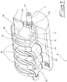
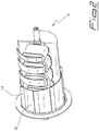
- a drum according to the present invention conventionally includes a generally cylindrical structure 6 of ferromagnetic material provided with a plurality of pole shoes (five in the illustrated embodiment) extending mainly in planes substantially parallel to each other and perpendicular to the longitudinal axis of the drum, said structure 6 being enclosed within a shell 12 of non-magnetic material that is rotatably mounted coaxially around structure 6 and is provided with longitudinal ribs 13.
- a first novel aspect of the present drum that distinguishes it from the above-described prior art drums resides in the fact that the pole bodies and the solenoids wound thereon are all arranged on a same side of a longitudinal midplane of the drum, the solenoids being wound on all pole bodies with their axes substantially perpendicular to the longitudinal drum axis and each pole body having a pole shoe arranged at the distal end thereof, the pole bodies extending in a plane substantially perpendicular to said drum axis and substantially parallel to the planes of the other pole bodies.
- the central pole bodies 1a preferably have a larger magnetic cross-section than the end pole bodies 1b, which have a magnetic cross-section reduced by 40-45% with respect to the former.
- magnetic cross-section is used here to indicate the cross-section of the magnetic element (pole body, pole shoe, circuit column, etc.) that is crossed substantially perpendicularly by the flux lines of the magnetic field.
- solenoids 2a wound on the central pole bodies 1a are larger than solenoids 2b wound on the end pole bodies 1b, which provide a magnetomotive force smaller by 25-35% with respect to the former, and the pole shoes located on top of the central pole bodies 1a are larger than the pole shoes located on top of the end pole bodies 1b, these latter pole shoes having a magnetic cross-section reduced by 35-40% with respect to the former.
- each pole shoe is made up of a first part 3a, 3b directly secured on the corresponding pole body 1a, 1b and of a second part 4a, 4b secured on said first part 3a, 3b.
- the latter is shaped like a circular segment and the second part 4a, 4b is shaped like a calendered plate having a radius of curvature corresponding to the radius of the active surface of the drum, i.e. the distance between the longitudinal axis of the drum and the radially distal surface of said second part, around which the non-magnetic shell 12 rotates with a play in the order of 10 mm.
- the circular segments 3a, 3b extend along an arc of about 76° ( Fig.3 , zone a ), the curved plates 4a, 4b cover the circular segments 3a, 3b and extend beyond them by about 34° in the direction of rotation of shell 12 ( Fig.3 , zone b ), and finally a conventional cancelling pole body 7 is located about 15° beyond the tails of the pole shoes ( Fig.3 , zone c).
- the overall operational arc ⁇ is therefore of about 125° ⁇ 5°, divided into 70°-80° of zone a of maximum activity in which each pole shoe has a magnetic cross-section preferably about twice the magnetic cross-section of the corresponding pole body, 30°-40° of zone b of progressive reduction of the magnetic field in which each pole shoe has a magnetic cross-section preferably about the same as the corresponding pole body and 10°-20° of zone c where the magnetic field is cancelled.
- the magnetic circuit column connecting the five polarities preferably includes a central square bar 8 of ferromagnetic steel at whose ends there are formed hubs 9 provided with seats for rotation bearings of shell 12 and for locking clamps for drum supports. On at least an end face of one of hubs 9 there is also preferably formed a stud 10 (e.g. square) for adjusting the position of the magnetic field with respect to the vertical axis Y-Y (see angle ⁇ in Fig.3 ).
- a stud 10 e.g. square
- central square bar 8 On two opposite sides of the central square bar 8 there are secured two longerons 11a, 11b of ferromagnetic steel so as to form with said bar 8 a plane having a width not smaller than the length of the pole bodies 1a, 1b, a magnetic cross-section not smaller than the magnetic cross-section of the end pole bodies 1b, and a length substantially equal to the length of the cylindrical structure 6 that defines the active table of the magnetic drum (indicatively 2-3 m of length for drums 1,5-1,8 m in diameter).
- longeron 11a arranged on the side of square bar 8 opposite with respect to the side where the cancelling pole body 7 is located is preferably wider than the other longeron 11b because the pole bodies 1a, 1b do not extend symmetrically with respect to the axis of rotation of shell 12 but project more on the side farther from the cancelling pole body 7.
- the five solenoids 2a, 2b wound on the corresponding pole bodies 1a, 1b are preferably connected in series and generate a magnetomotive force (with the above-mentioned percentage ratios) that determines a magnetic field and a corresponding magnetic field gradient capable of attracting, in the operational zone, ferromagnetic scrap of any shape factor even from a great distance when it is still on the feed slope A, which preferably consists of a vibrating chute with a comb-shaped end portion.
- Ribs 13 of shell 12 are similar in height to ribs 28 of prior art drums, preferably about 65 mm, and therefore do not hinder the fall of the inert material in the attraction zone since the distance d between the vibrating chute A and the drum shell 12 is preferably about 250 mm (see Fig.3 ).
- Ribs 13 are sufficient to support the advancing of small-sized ferromagnetic scrap while medium- and large-sized pieces weighing from some quintals to about a ton are attracted and kept retained on shell 12 by the magnetic field, without any polarity change, until they are drawn to the release zone beyond the operational arc ⁇ where they have already crossed the vertical axis Y-Y and fall by gravity.
- the resisting torque of shell 12 is discharged on bearings whose friction coefficient is obviously low, whereby the driving torque required to the motor system is not excessive.
- the comb-shaped portion also has the function of dropping the soil mixed with rust (iron oxide) before it reaches the end of slope A where it could be attracted by the drum, whereas small-sized ferromagnetic scrap is usually attracted by the drum even from the comb-shaped portion.
- this new type of electromagnetic drum is suitable to attract and draw ferromagnetic scrap of any size and with a weight in the range from about 0,01 to 1000 kg, whereby it can effectively clean any kind of ferromagnetic scrap suitable to be loaded into a melting furnace of a steel mill.
Landscapes
- Storage Of Web-Like Or Filamentary Materials (AREA)
- Dynamo-Electric Clutches, Dynamo-Electric Brakes (AREA)
- Electromagnets (AREA)
Description
- The present invention relates to magnetic separators, and in particular to an electromagnetic drum for cleaning the ferromagnetic scrap of medium and large size used in steel mills.
- It is known that the scrap of different origin normally used in steel mills contains between about 3 and 12% of non-ferromagnetic material that is mostly made up of stony material, sand, rubber, plastic and various metals such as copper, aluminium, bronze, brass, zinc, etc. which are highly detrimental to the quality of the steel that is meant to be produced from said scrap. These pollutants cause a significant increase in power consumption, in quicklime consumption and in the production of waste, which results in a lower quality and a higher cost of the steel thus produced.
- It is presently difficult to meet the requirements of European Union rules that define the criteria according to which some types of metallic scrap are no longer considered waste because the scrap being used can be small or large in size, light or heavy, homogeneous or not homogeneous and therefore a single magnetic separator is not able to effectively operate on different types of scrap.
- In particular, it is difficult to clean the larger and heavier scrap usually referred to as HMS 1 or HMS 2 (acronym of the expression Heavy Metal Scrap) which consists of material from shearing, rail or naval recovery, deep drawn sheets, pieces of billets, blooms and beams, etc. This type of scrap can reach a very large size and weight in the order of several quintals or even a ton.
- Known electromagnetic drums used to clean ferromagnetic scrap are normally made with two or three longitudinal polarities, i.e. extending mainly in a plane parallel to the longitudinal drum axis, that are perpendicular with respect to the feed flow of the mixed ferromagnetic material from which the inert material must be removed. A typical example of a prior art two-pole drum is disclosed in
US 2009/0159511 and illustrated infigures 5 and 6 , that show afirst solenoid 21 wound around a first pole body provided with arelevant pole shoe 22 to form a first polarity, which generates a magnetomotive force equal to about 2/3 of the total magnetomotive force of the drum. As a consequence, the remaining 1/3 is generated by the second polarity formed by asecond solenoid 23 wound on a second body with arelevant shoe 24, whereas in the case of three-pole drums (e.g.DE 2007529A1 ,Figs.2 and3 ) the division is about 50% of the total for the first polarity, 30-35% for the second one and 15-20% for the third one. - Both two-pole and three-pole drums are also provided with a further
inactive pole body 25, of reduced section and without any solenoid wound thereon, which is arranged beyond the active polarities (in the direction of rotation of the drum) and only has the function of cancelling the magnetic field to facilitate the release of the lighter ferromagnetic material. The operational arc of the magnetic field CM generated by the drum is usually of about 180° in the circumferential direction, with the axis of attraction a-a corresponding to the axis of greater magnetomotive force that is perpendicular to the axis of rotation and arranged at an angle α varying between 15° and 45°, depending on the design parameters, with respect to the vertical axis Y-Y in quadrant III of a Cartesian reference system XY (in the illustrated example of clockwise rotation centered in the origin). - In this case the material release zone is located in quadrant I at the cancelling
pole body 25, and during the path of about 180° in the circumferential direction from the attraction zone to the release zone the attractedferromagnetic material 26 must pass through two or three successive polarities of opposite sign. The change of polarity opposes the advancing of theferromagnetic material 26, as readily understood also because the change of polarity is from a stronger polarity to a weaker polarity; moreover also gravity opposes the advancing that takes place upwards. - The sum of these effects that oppose the advancing results in this type of electromagnetic drums being suitable only for homogeneous and small- or medium-sized ferromagnetic scrap, such as shredded vehicles (so-called "proler"), in which the inert material to be eliminated is essentially made up of rubber, plastic and non-magnetic metals with a similar size and most of the
inert material 27 is removed by free fall in the attraction zone. - The remaining part of the
inert material 27, generally lighter and trapped by theferromagnetic material 26, is released during the change of polarity when theferromagnetic material 26 tends to roll, this being possible because in this phase the advancing ofmaterial 26 is due to a mechanical driving carried out bylongitudinal ribs 28 applied on the rotatingshell 29 of the drum. Theseribs 28 must simultaneously raisematerial 26 against gravity and overcome the opposing magnetic action at the polarity change, yet they cannot be too high otherwise they would hinder the fall of the inert material and would end up dragging along too much of it thus making the cleaning action ineffective. - From the above it is readily evident that this type of electromagnetic drum is not suitable to clean medium- or large-sized ferromagnetic scrap, since it has at least two kinds of drawbacks. A first drawback stems from the fact that the scrap having such a size would easily climb over
ribs 28 during the polarity change, piling up in the attraction zone until seizure ofshell 29. Furthermore, even in the presence of muchhigher ribs 28, in the above-mentioned polarity change phase the drum would require an enormous driving torque to turn over pieces weighing even some quintals that must overcome the attraction of the stronger polarity and be drawn upwards. - Another type of known electromagnetic drum, illustrated in
figures 7 and 8 , provides on the contrary for radial pole shoes extending perpendicularly with respect to the longitudinal drum axis and therefore parallel to the feed flow of the material to be treated. In this case,radial pole shoes 31 are arranged perpendicularly to the longitudinal drum axis andcircular solenoids 32 are interposed between theradial pole shoes 31 and wound onradial pole bodies 33 that coaxially enclose the drum shaft and are integrated therewith. - Still another type of known electromagnetic drum is shown in
US 2950008 which discloses a drum with two solenoids wound on respective pole bodies provided with pole shoes arranged at the distal ends thereof, each solenoid having a solenoid axis perpendicular to a central longitudinal axis of the drum and each pole body extending in a plane perpendicular to the drum axis and. - These pole bodies are located at intermediate positions between a central pole body and two end pole bodies that have neither solenoids wound thereon nor pole shoes arranged at the distal ends thereof, said unwound pole bodies constituting regions of great magnetic dispersion. The resulting magnetic field is quite wavy in the longitudinal direction with values at the central unwound pole which are about half the values at the adjacent wound poles.
- Furthermore in the drum disclosed in this document the poles are mounted on a plate that is offset from the center of the drum at a position beyond the drum axis thus resulting in a longer ferromagnetic circuit with higher dispersion. This position of the support plate is made necessary by the fact of having only two wound poles whereby in order to obtain a higher magnetic field the two solenoids must be higher, i.e. have more turns, and thus must extend beyond the drum midplane.
- These other two types of drums are normally employed for an opposite function with respect to the above-described drums, namely to clean inert materials polluted by ferromagnetic material that represents a small fraction of the material to be treated.
- Although in these types of drum the ferromagnetic material does not have to pass through successive polarities of opposite sign in its circumferential path around the drum, and therefore the required torque would not be too high, nonetheless they are not suitable to clean medium- or large-sized ferromagnetic scrap due to at least two kinds of drawbacks. In the first place these types of drum would require a significant oversizing of the parts to be used for this function, since they are designed to remove small amounts of ferromagnetic material, and therefore would result expensive and bulky.
- Secondly, their constructive shape is magnetically dispersive and poorly effective in performing the required function in the active zone, namely on the surface of the rotating shell. In particular, in the prior art drum illustrated in
Figs. 7, 8 given the great distance betweensolenoids 32 and the active zone of therotating shell 34 the dispersion of the magnetic field with such a structure can be estimated at 50-60% (it should be noted that the axis of attraction corresponding to the axis of the greatest magnetomotive force in this case coincides with the axis of rotation r-r of shell 34). - In other words, with such prior art drums the magnetic field and the magnetic field gradient are insufficient both to attract the ferromagnetic material from a distance suitable to determine an adequate fall zone for the inert material, and to draw ferromagnetic pieces weighing hundreds of kilograms and/or having a large size.
- Therefore the object of the present invention is to provide an electromagnetic drum which overcomes the above-mentioned drawbacks. This object is achieved by means of a drum in which central, intermediate and end pole bodies all have solenoids wound thereon and pole shoes arranged at the distal ends thereof, said pole bodies being all arranged on a same side of a longitudinal midplane of the drum, the solenoids having their axes substantially perpendicular to the longitudinal drum axis and each pole body extending mainly in a plane substantially perpendicular to said drum axis and substantially parallel to the planes of the other pole bodies, such that also the axis of attraction is perpendicular to said drum axis and there is no polarity change in the circumferential direction. Other advantageous features are disclosed in the dependent claims.
- The main advantage of the drum according to the present invention is therefore that of providing a magnetic field suitable to draw even very large and heavy ferromagnetic scrap with a very low dispersion of the magnetic field, without having to face polarity changes along the circumferential path and while keeping cost and size similar to those of conventional drums. In this way it is possible to effectively clean even HMS 1 and HMS 2 scrap, thus increasing the quality and decreasing the cost of the steel produced from said scrap.
- These and other advantages and characteristics of the electromagnetic drum according to the present invention will be clear to those skilled in the art from the following detailed description of an embodiment thereof, with reference to the annexed drawings wherein:
-
Fig.1 is a perspective view of the internal components of the drum with two solenoids removed for the sake of clarity; -
Fig.2 is a perspective view of the drum with a portion removed; -
Fig.3 is a cross-sectional view of the drum showing its geometrical parameters; -
Fig.4 is a view similar to the preceding one that shows the operation of the drum; and -
Figs.5-8 show two types of conventional drums as previously explained. - With reference to
figures 1-4 , there is seen that a drum according to the present invention conventionally includes a generallycylindrical structure 6 of ferromagnetic material provided with a plurality of pole shoes (five in the illustrated embodiment) extending mainly in planes substantially parallel to each other and perpendicular to the longitudinal axis of the drum, saidstructure 6 being enclosed within ashell 12 of non-magnetic material that is rotatably mounted coaxially aroundstructure 6 and is provided withlongitudinal ribs 13. - A first novel aspect of the present drum that distinguishes it from the above-described prior art drums resides in the fact that the pole bodies and the solenoids wound thereon are all arranged on a same side of a longitudinal midplane of the drum, the solenoids being wound on all pole bodies with their axes substantially perpendicular to the longitudinal drum axis and each pole body having a pole shoe arranged at the distal end thereof, the pole bodies extending in a plane substantially perpendicular to said drum axis and substantially parallel to the planes of the other pole bodies.
- The
central pole bodies 1a preferably have a larger magnetic cross-section than theend pole bodies 1b, which have a magnetic cross-section reduced by 40-45% with respect to the former. The expression "magnetic cross-section" is used here to indicate the cross-section of the magnetic element (pole body, pole shoe, circuit column, etc.) that is crossed substantially perpendicularly by the flux lines of the magnetic field. - Correspondingly, also
solenoids 2a wound on thecentral pole bodies 1a are larger thansolenoids 2b wound on theend pole bodies 1b, which provide a magnetomotive force smaller by 25-35% with respect to the former, and the pole shoes located on top of thecentral pole bodies 1a are larger than the pole shoes located on top of theend pole bodies 1b, these latter pole shoes having a magnetic cross-section reduced by 35-40% with respect to the former. - More specifically, in a second novel aspect of the invention, each pole shoe is made up of a
first part corresponding pole body second part 4a, 4b secured on saidfirst part second part 4a, 4b is shaped like a calendered plate having a radius of curvature corresponding to the radius of the active surface of the drum, i.e. the distance between the longitudinal axis of the drum and the radially distal surface of said second part, around which thenon-magnetic shell 12 rotates with a play in the order of 10 mm. - In the preferred embodiment illustrated in the figures, the
circular segments Fig.3 , zone a), thecurved plates 4a, 4b cover thecircular segments Fig.3 , zone b), and finally a conventionalcancelling pole body 7 is located about 15° beyond the tails of the pole shoes (Fig.3 , zone c). The overall operational arc β is therefore of about 125°±5°, divided into 70°-80° of zone a of maximum activity in which each pole shoe has a magnetic cross-section preferably about twice the magnetic cross-section of the corresponding pole body, 30°-40° of zone b of progressive reduction of the magnetic field in which each pole shoe has a magnetic cross-section preferably about the same as the corresponding pole body and 10°-20° of zone c where the magnetic field is cancelled. - The magnetic circuit column connecting the five polarities preferably includes a
central square bar 8 of ferromagnetic steel at whose ends there are formed hubs 9 provided with seats for rotation bearings ofshell 12 and for locking clamps for drum supports. On at least an end face of one of hubs 9 there is also preferably formed a stud 10 (e.g. square) for adjusting the position of the magnetic field with respect to the vertical axis Y-Y (see angle γ inFig.3 ). - On two opposite sides of the
central square bar 8 there are secured twolongerons pole bodies end pole bodies 1b, and a length substantially equal to the length of thecylindrical structure 6 that defines the active table of the magnetic drum (indicatively 2-3 m of length for drums 1,5-1,8 m in diameter). - It should be noted that
longeron 11a arranged on the side ofsquare bar 8 opposite with respect to the side where the cancellingpole body 7 is located is preferably wider than theother longeron 11b because thepole bodies shell 12 but project more on the side farther from the cancellingpole body 7. - The five
solenoids corresponding pole bodies -
Ribs 13 ofshell 12 are similar in height toribs 28 of prior art drums, preferably about 65 mm, and therefore do not hinder the fall of the inert material in the attraction zone since the distance d between the vibrating chute A and thedrum shell 12 is preferably about 250 mm (seeFig.3 ). - In the light of the description above the simple and effective operation of the electromagnetic drum according to the present invention is readily understood.
-
Ribs 13 are sufficient to support the advancing of small-sized ferromagnetic scrap while medium- and large-sized pieces weighing from some quintals to about a ton are attracted and kept retained onshell 12 by the magnetic field, without any polarity change, until they are drawn to the release zone beyond the operational arc β where they have already crossed the vertical axis Y-Y and fall by gravity. The resisting torque ofshell 12 is discharged on bearings whose friction coefficient is obviously low, whereby the driving torque required to the motor system is not excessive. - The small-sized pieces of inert material fall through the comb-shaped portion at the end of the feed slope A, while the inert materials of larger size fall at the end of slope A thanks to the distance d from
shell 12. It should be noted that the comb-shaped portion also has the function of dropping the soil mixed with rust (iron oxide) before it reaches the end of slope A where it could be attracted by the drum, whereas small-sized ferromagnetic scrap is usually attracted by the drum even from the comb-shaped portion. - Therefore it is clear that this new type of electromagnetic drum is suitable to attract and draw ferromagnetic scrap of any size and with a weight in the range from about 0,01 to 1000 kg, whereby it can effectively clean any kind of ferromagnetic scrap suitable to be loaded into a melting furnace of a steel mill.
- It is clear that the above-described and illustrated embodiment of the drum according to the invention is just an example susceptible of various modifications. In particular, various parameters such as the number of polarities, the dimensional ratios between the various components, the number and size of
ribs 13 as well as the extension of the operational arc β may change according to specific manufacturing needs as long as the general structure of the drum is maintained.
Claims (14)
- Electromagnetic drum for magnetic separator comprising a generally cylindrical structure (6) of ferromagnetic material provided with a plurality of solenoids (2a, 2b) wound on pole bodies (1a, 1b) having pole shoes arranged at the radially distal end thereof, each solenoid (2a, 2b) having a solenoid axis substantially perpendicular to a central longitudinal axis of the drum and each pole body (1a, 1b) extending in a plane substantially perpendicular to said drum axis and substantially parallel to the planes of the other pole bodies (1a, 1b), said cylindrical structure (6) being enclosed within a cylindrical shell (12) of non-magnetic material that is rotatably mounted coaxially around the cylindrical structure (6) and is provided with longitudinal ribs (13), a further pole body (7) without a solenoid wound thereon which only serves the purpose of cancelling the magnetic field being arranged beyond said solenoids (2a, 2b) in the direction of rotation of said shell (12) in a plane substantially perpendicular to the planes of the pole bodies (1a, 1b), characterized in that it includes central (1a) and end (1b) pole bodies all having solenoids (2a, 2b) wound thereon and pole shoes arranged at the radially distal ends thereof and in that said pole bodies (1a, 1b) and the solenoids (2a, 2b) wound thereon are all arranged on a same side of a longitudinal midplane of the drum.
- Drum according to claim 1, characterized in that the central pole bodies (1a) have a magnetic cross-section greater than the end pole bodies (1b) wherein the magnetic cross-section is the cross-section that is crossed substantially perpendicularly by the flux lines of the magnetic field, and the solenoids (2a) wound on the central pole bodies (1a) are larger than the solenoids (2b) wound on the end pole bodies (1b).
- Drum according to claim 2, characterized in that the end pole bodies (1b) have a magnetic cross-section reduced by 40-45% with respect to the central pole bodies (1a) wherein the magnetic cross-section is the cross-section that is crossed substantially perpendicularly by the flux lines of the magnetic field.
- Drum according to claim 2, characterized in that the solenoids (2b) wound on the end pole bodies (1b) are suitable to provide a magnetomotive force smaller by 25-35% with respect to the solenoids (2a) wound on the central pole bodies (1a).
- Drum according to any of the preceding claims, characterized in that the central pole bodies (1a) have pole shoes larger than the end pole bodies (1b).
- Drum according to claim 5, characterized in that the pole shoes of the end pole bodies (1b) have a magnetic cross-section reduced by 35-40% with respect to the pole shoes of the central pole bodies (1a) wherein the magnetic cross-section is the cross-section that is crossed substantially perpendicularly by the flux lines of the magnetic field.
- Drum according to any of the preceding claims, characterized in that each pole shoe is made up of a first part (3a, 3b) shaped like a circular segment and directly secured on the corresponding pole body (1a, 1b), and of a second part (4a, 4b) secured on said first part (3a, 3b) and shaped like a calendered plate having a radius of curvature corresponding to the distance between the longitudinal axis of the drum and the radially distal surface of said second part (4a, 4b).
- Drum according to claim 7, characterized in that the circular segments (3a, 3b) extend along an arc of 70°-80°, the curved plates (4a, 4b) cover said circular segments (3a, 3b) extending beyond them by 30°-40° in the direction of rotation of the shell (12) and the further pole body (7) for cancelling the magnetic field is located 10°-20° beyond said curved plates (4a, 4b).
- Drum according to any of the preceding claims, characterized in that the plurality of pole bodies (1a, 1b) are connected through a magnetic circuit column having a width not smaller than the length of said pole bodies (1a, 1b), a magnetic cross-section not smaller than the magnetic cross-section of the end pole bodies (1b) wherein the magnetic cross-section is the cross-section that is crossed substantially perpendicularly by the flux lines of the magnetic field, and a length substantially equal to the length of the cylindrical structure (6).
- Drum according to claim 9, characterized in that the magnetic circuit column is made up of a central square bar (8) at whose ends there are formed hubs (9) provided with seats for rotation bearings of the shell (12) and for locking clamps for drum supports, and of two lateral longerons (11a, 11b) arranged on opposite sides of said central square bar (8).
- Drum according to claim 10, characterized in that the longeron (11a) arranged on the side farther from the cancelling pole body (7) is wider than the other longeron (11b).
- Drum according to claim 10, characterized in that on at least an end face of one of the hubs (9) there is formed a stud (10) for adjusting the position of the magnetic field.
- Drum according to any of the preceding claims, characterized in that the solenoids (2a, 2b) are connected in series.
- Magnetic separator comprising an electromagnetic drum according to any of the preceding claims, characterized in that it further includes a slope (A) for feeding the material to be treated which consists of a vibrating chute with a comb-shaped end portion that is spaced substantially 250 mm from the drum shell (12), the ribs (13) of said shell (12) being substantially 65 mm high.
Applications Claiming Priority (2)
| Application Number | Priority Date | Filing Date | Title |
|---|---|---|---|
| IT001902A ITMI20121902A1 (en) | 2012-11-08 | 2012-11-08 | ELECTROMAGNETIC DRUM FOR CLEANING FERROMAGNETIC MEDIUM AND LARGE DIMENSIONS |
| PCT/IB2013/059810 WO2014072892A1 (en) | 2012-11-08 | 2013-10-31 | Electromagnetic drum for cleaning ferromagnetic scrap of medium and large size |
Publications (2)
| Publication Number | Publication Date |
|---|---|
| EP2908955A1 EP2908955A1 (en) | 2015-08-26 |
| EP2908955B1 true EP2908955B1 (en) | 2017-03-08 |
Family
ID=47561721
Family Applications (1)
| Application Number | Title | Priority Date | Filing Date |
|---|---|---|---|
| EP13820934.1A Active EP2908955B1 (en) | 2012-11-08 | 2013-10-31 | Electromagnetic drum for cleaning ferromagnetic scrap of medium and large size |
Country Status (6)
| Country | Link |
|---|---|
| US (1) | US9475063B2 (en) |
| EP (1) | EP2908955B1 (en) |
| KR (1) | KR20150082302A (en) |
| ES (1) | ES2625779T3 (en) |
| IT (1) | ITMI20121902A1 (en) |
| WO (1) | WO2014072892A1 (en) |
Families Citing this family (2)
| Publication number | Priority date | Publication date | Assignee | Title |
|---|---|---|---|---|
| ITMI20121901A1 (en) * | 2012-11-08 | 2014-05-09 | Sgm Gantry Spa | DRUM FOR MAGNETIC SEPARATOR AND RELATIVE PRODUCTION METHOD |
| US20240216927A1 (en) * | 2022-12-30 | 2024-07-04 | Bluestreak Equipment Inc. | Ceramic powered steel shot magnetic sweeper apparatus |
Family Cites Families (21)
| Publication number | Priority date | Publication date | Assignee | Title |
|---|---|---|---|---|
| US1380871A (en) * | 1921-06-07 | swart | ||
| US500606A (en) * | 1893-07-04 | Device for and method of adjusting and equalizing the magnetic density in the pole-pieces | ||
| US1324529A (en) * | 1919-12-09 | Magnetic drum-separator | ||
| US1527810A (en) * | 1922-08-18 | 1925-02-24 | Dings Magnetic Separator Co | Magnetic separator |
| US1714171A (en) * | 1926-01-12 | 1929-05-21 | August F Jobke | Magnetic separator |
| DE622785C (en) * | 1931-09-19 | 1935-12-06 | Steinert Electromagnetbau G M | Drum magnetic separator |
| DE885685C (en) | 1951-03-02 | 1953-08-06 | Demag Ag | Air purging device for hammer drills |
| DE882682C (en) * | 1951-07-04 | 1953-07-09 | Kloeckner Humboldt Deutz Ag | Magnetic separator |
| US2750035A (en) * | 1954-10-19 | 1956-06-12 | Stearns Magnetic Inc | Magnetic separator pulley |
| US2950008A (en) * | 1956-05-18 | 1960-08-23 | Indiana General Corp | Drum type magnetic separator |
| DE1228213B (en) * | 1964-12-22 | 1966-11-10 | Steinert Elektromagnetbau | Strong magnetic separator |
| US3365599A (en) * | 1965-03-17 | 1968-01-23 | Wehr Corp | Magnetic circuit |
| US3426897A (en) * | 1966-12-01 | 1969-02-11 | United States Steel Corp | Magnetic separator |
| US3552564A (en) * | 1967-04-25 | 1971-01-05 | Burgener Technical Enterprises | Ferromagnetic ore concentrator and method of processing ores therewith |
| CH502843A (en) * | 1967-05-23 | 1971-02-15 | Fritz Lothar | Magnetic separator |
| DE2007529A1 (en) * | 1970-02-19 | 1971-09-09 | Steinert Elektromagnetbau | Magnetic separator with axially arranged pole system |
| ATE549092T1 (en) * | 2006-06-15 | 2012-03-15 | Sgm Gantry Spa | ELECTROMAGNETIC SEPARATOR AND SEPARATION PROCESS OF FERROMAGNETIC MATERIALS |
| WO2011085001A2 (en) * | 2010-01-05 | 2011-07-14 | Eriez Manufacturing Co. | Permanent magnet drum separator with movable magnetic elements |
| US8561807B2 (en) * | 2011-12-09 | 2013-10-22 | Eriez Manufacturing Co. | Magnetic drum separator with an electromagnetic pickup magnet having a core in a tapered shape |
| ITMI20122047A1 (en) * | 2012-11-30 | 2014-05-31 | Sgm Gantry Spa | LIFT WITH ELECTROPERMANENT MAGNETS |
| US9108203B2 (en) * | 2013-03-01 | 2015-08-18 | Eriez Manufacturing Co. | Magnetic drum separator with an outer shell having traction elements |
-
2012
- 2012-11-08 IT IT001902A patent/ITMI20121902A1/en unknown
-
2013
- 2013-10-31 KR KR1020157012201A patent/KR20150082302A/en not_active Application Discontinuation
- 2013-10-31 US US14/439,853 patent/US9475063B2/en active Active
- 2013-10-31 EP EP13820934.1A patent/EP2908955B1/en active Active
- 2013-10-31 WO PCT/IB2013/059810 patent/WO2014072892A1/en active Application Filing
- 2013-10-31 ES ES13820934.1T patent/ES2625779T3/en active Active
Non-Patent Citations (1)
| Title |
|---|
| None * |
Also Published As
| Publication number | Publication date |
|---|---|
| WO2014072892A1 (en) | 2014-05-15 |
| ES2625779T3 (en) | 2017-07-20 |
| ITMI20121902A1 (en) | 2014-05-09 |
| KR20150082302A (en) | 2015-07-15 |
| EP2908955A1 (en) | 2015-08-26 |
| US9475063B2 (en) | 2016-10-25 |
| US20150290656A1 (en) | 2015-10-15 |
Similar Documents
| Publication | Publication Date | Title |
|---|---|---|
| EP2916958B1 (en) | Drum for magnetic separator and relevant production method | |
| US3489280A (en) | Magnetic separator having field shaping poles | |
| US3168464A (en) | Permanent magnetic separator | |
| WO2016023628A1 (en) | Magnetic damper for vibration absorbers | |
| EP2908955B1 (en) | Electromagnetic drum for cleaning ferromagnetic scrap of medium and large size | |
| EP0022758B1 (en) | Wear and abrasion resistant wall structure, particularly for mills for grinding a charge comprising magnetic material | |
| US8561807B2 (en) | Magnetic drum separator with an electromagnetic pickup magnet having a core in a tapered shape | |
| JP2009172590A (en) | Rotary-drum type magnetic separator | |
| US2992737A (en) | Method and means for variation of magnetic strength of permanent magnetic drums | |
| KR102298216B1 (en) | Nonferrous metal screening system using eddy current. | |
| US4296865A (en) | Magnetic separator having two rotating magnetic drums of opposite polarity | |
| US2992736A (en) | Magnetic separator | |
| JP2005262058A (en) | Method and apparatus for magnetic sorting | |
| GB1576071A (en) | Magnetic separator | |
| US20140299518A1 (en) | Magnetic drum for the magnetic separation of iron particles including at least 18 straight magnetic plates | |
| EP0362380A4 (en) | Ferrohydrostatic separator | |
| US2950008A (en) | Drum type magnetic separator | |
| US1365965A (en) | Magnetic separating apparatus | |
| SU1074602A1 (en) | Electromagnetic separator | |
| USRE16673E (en) | Electkomagnetic apbon feedeb | |
| DE442643C (en) | Magnetic drum separator | |
| RU2301709C2 (en) | Magnetic system | |
| KR100428846B1 (en) | High efficient magnetic separator for removing fine iron-particles on the plates and sheets | |
| DE202005017952U1 (en) | Apparatus for separating materials containing nonferrous metals, comprising a conveyor for transporting the material to a nonferrous metal separator, comprises a magnetic iron separator mounted above the conveyor | |
| DE10394120T5 (en) | magnetic bearings |
Legal Events
| Date | Code | Title | Description |
|---|---|---|---|
| PUAI | Public reference made under article 153(3) epc to a published international application that has entered the european phase |
Free format text: ORIGINAL CODE: 0009012 |
|
| 17P | Request for examination filed |
Effective date: 20150518 |
|
| AK | Designated contracting states |
Kind code of ref document: A1 Designated state(s): AL AT BE BG CH CY CZ DE DK EE ES FI FR GB GR HR HU IE IS IT LI LT LU LV MC MK MT NL NO PL PT RO RS SE SI SK SM TR |
|
| AX | Request for extension of the european patent |
Extension state: BA ME |
|
| DAX | Request for extension of the european patent (deleted) | ||
| 17Q | First examination report despatched |
Effective date: 20160408 |
|
| GRAP | Despatch of communication of intention to grant a patent |
Free format text: ORIGINAL CODE: EPIDOSNIGR1 |
|
| INTG | Intention to grant announced |
Effective date: 20161021 |
|
| GRAS | Grant fee paid |
Free format text: ORIGINAL CODE: EPIDOSNIGR3 |
|
| GRAA | (expected) grant |
Free format text: ORIGINAL CODE: 0009210 |
|
| AK | Designated contracting states |
Kind code of ref document: B1 Designated state(s): AL AT BE BG CH CY CZ DE DK EE ES FI FR GB GR HR HU IE IS IT LI LT LU LV MC MK MT NL NO PL PT RO RS SE SI SK SM TR |
|
| REG | Reference to a national code |
Ref country code: GB Ref legal event code: FG4D |
|
| REG | Reference to a national code |
Ref country code: CH Ref legal event code: EP Ref country code: AT Ref legal event code: REF Ref document number: 873042 Country of ref document: AT Kind code of ref document: T Effective date: 20170315 |
|
| REG | Reference to a national code |
Ref country code: IE Ref legal event code: FG4D |
|
| REG | Reference to a national code |
Ref country code: DE Ref legal event code: R096 Ref document number: 602013018401 Country of ref document: DE |
|
| REG | Reference to a national code |
Ref country code: LT Ref legal event code: MG4D |
|
| REG | Reference to a national code |
Ref country code: NL Ref legal event code: MP Effective date: 20170308 |
|
| REG | Reference to a national code |
Ref country code: ES Ref legal event code: FG2A Ref document number: 2625779 Country of ref document: ES Kind code of ref document: T3 Effective date: 20170720 |
|
| PG25 | Lapsed in a contracting state [announced via postgrant information from national office to epo] |
Ref country code: FI Free format text: LAPSE BECAUSE OF FAILURE TO SUBMIT A TRANSLATION OF THE DESCRIPTION OR TO PAY THE FEE WITHIN THE PRESCRIBED TIME-LIMIT Effective date: 20170308 Ref country code: LT Free format text: LAPSE BECAUSE OF FAILURE TO SUBMIT A TRANSLATION OF THE DESCRIPTION OR TO PAY THE FEE WITHIN THE PRESCRIBED TIME-LIMIT Effective date: 20170308 Ref country code: GR Free format text: LAPSE BECAUSE OF FAILURE TO SUBMIT A TRANSLATION OF THE DESCRIPTION OR TO PAY THE FEE WITHIN THE PRESCRIBED TIME-LIMIT Effective date: 20170609 Ref country code: HR Free format text: LAPSE BECAUSE OF FAILURE TO SUBMIT A TRANSLATION OF THE DESCRIPTION OR TO PAY THE FEE WITHIN THE PRESCRIBED TIME-LIMIT Effective date: 20170308 Ref country code: NO Free format text: LAPSE BECAUSE OF FAILURE TO SUBMIT A TRANSLATION OF THE DESCRIPTION OR TO PAY THE FEE WITHIN THE PRESCRIBED TIME-LIMIT Effective date: 20170608 |
|
| REG | Reference to a national code |
Ref country code: AT Ref legal event code: MK05 Ref document number: 873042 Country of ref document: AT Kind code of ref document: T Effective date: 20170308 |
|
| PG25 | Lapsed in a contracting state [announced via postgrant information from national office to epo] |
Ref country code: RS Free format text: LAPSE BECAUSE OF FAILURE TO SUBMIT A TRANSLATION OF THE DESCRIPTION OR TO PAY THE FEE WITHIN THE PRESCRIBED TIME-LIMIT Effective date: 20170308 Ref country code: BG Free format text: LAPSE BECAUSE OF FAILURE TO SUBMIT A TRANSLATION OF THE DESCRIPTION OR TO PAY THE FEE WITHIN THE PRESCRIBED TIME-LIMIT Effective date: 20170608 Ref country code: LV Free format text: LAPSE BECAUSE OF FAILURE TO SUBMIT A TRANSLATION OF THE DESCRIPTION OR TO PAY THE FEE WITHIN THE PRESCRIBED TIME-LIMIT Effective date: 20170308 Ref country code: SE Free format text: LAPSE BECAUSE OF FAILURE TO SUBMIT A TRANSLATION OF THE DESCRIPTION OR TO PAY THE FEE WITHIN THE PRESCRIBED TIME-LIMIT Effective date: 20170308 |
|
| PG25 | Lapsed in a contracting state [announced via postgrant information from national office to epo] |
Ref country code: NL Free format text: LAPSE BECAUSE OF FAILURE TO SUBMIT A TRANSLATION OF THE DESCRIPTION OR TO PAY THE FEE WITHIN THE PRESCRIBED TIME-LIMIT Effective date: 20170308 |
|
| REG | Reference to a national code |
Ref country code: FR Ref legal event code: PLFP Year of fee payment: 5 |
|
| PG25 | Lapsed in a contracting state [announced via postgrant information from national office to epo] |
Ref country code: EE Free format text: LAPSE BECAUSE OF FAILURE TO SUBMIT A TRANSLATION OF THE DESCRIPTION OR TO PAY THE FEE WITHIN THE PRESCRIBED TIME-LIMIT Effective date: 20170308 Ref country code: RO Free format text: LAPSE BECAUSE OF FAILURE TO SUBMIT A TRANSLATION OF THE DESCRIPTION OR TO PAY THE FEE WITHIN THE PRESCRIBED TIME-LIMIT Effective date: 20170308 Ref country code: AT Free format text: LAPSE BECAUSE OF FAILURE TO SUBMIT A TRANSLATION OF THE DESCRIPTION OR TO PAY THE FEE WITHIN THE PRESCRIBED TIME-LIMIT Effective date: 20170308 Ref country code: SK Free format text: LAPSE BECAUSE OF FAILURE TO SUBMIT A TRANSLATION OF THE DESCRIPTION OR TO PAY THE FEE WITHIN THE PRESCRIBED TIME-LIMIT Effective date: 20170308 Ref country code: CZ Free format text: LAPSE BECAUSE OF FAILURE TO SUBMIT A TRANSLATION OF THE DESCRIPTION OR TO PAY THE FEE WITHIN THE PRESCRIBED TIME-LIMIT Effective date: 20170308 |
|
| PG25 | Lapsed in a contracting state [announced via postgrant information from national office to epo] |
Ref country code: IS Free format text: LAPSE BECAUSE OF FAILURE TO SUBMIT A TRANSLATION OF THE DESCRIPTION OR TO PAY THE FEE WITHIN THE PRESCRIBED TIME-LIMIT Effective date: 20170708 Ref country code: SM Free format text: LAPSE BECAUSE OF FAILURE TO SUBMIT A TRANSLATION OF THE DESCRIPTION OR TO PAY THE FEE WITHIN THE PRESCRIBED TIME-LIMIT Effective date: 20170308 Ref country code: PT Free format text: LAPSE BECAUSE OF FAILURE TO SUBMIT A TRANSLATION OF THE DESCRIPTION OR TO PAY THE FEE WITHIN THE PRESCRIBED TIME-LIMIT Effective date: 20170710 Ref country code: PL Free format text: LAPSE BECAUSE OF FAILURE TO SUBMIT A TRANSLATION OF THE DESCRIPTION OR TO PAY THE FEE WITHIN THE PRESCRIBED TIME-LIMIT Effective date: 20170308 |
|
| REG | Reference to a national code |
Ref country code: DE Ref legal event code: R097 Ref document number: 602013018401 Country of ref document: DE |
|
| PLBE | No opposition filed within time limit |
Free format text: ORIGINAL CODE: 0009261 |
|
| STAA | Information on the status of an ep patent application or granted ep patent |
Free format text: STATUS: NO OPPOSITION FILED WITHIN TIME LIMIT |
|
| PG25 | Lapsed in a contracting state [announced via postgrant information from national office to epo] |
Ref country code: DK Free format text: LAPSE BECAUSE OF FAILURE TO SUBMIT A TRANSLATION OF THE DESCRIPTION OR TO PAY THE FEE WITHIN THE PRESCRIBED TIME-LIMIT Effective date: 20170308 |
|
| 26N | No opposition filed |
Effective date: 20171211 |
|
| PG25 | Lapsed in a contracting state [announced via postgrant information from national office to epo] |
Ref country code: SI Free format text: LAPSE BECAUSE OF FAILURE TO SUBMIT A TRANSLATION OF THE DESCRIPTION OR TO PAY THE FEE WITHIN THE PRESCRIBED TIME-LIMIT Effective date: 20170308 |
|
| PG25 | Lapsed in a contracting state [announced via postgrant information from national office to epo] |
Ref country code: MC Free format text: LAPSE BECAUSE OF FAILURE TO SUBMIT A TRANSLATION OF THE DESCRIPTION OR TO PAY THE FEE WITHIN THE PRESCRIBED TIME-LIMIT Effective date: 20170308 |
|
| REG | Reference to a national code |
Ref country code: CH Ref legal event code: PL |
|
| REG | Reference to a national code |
Ref country code: ES Ref legal event code: PC2A Owner name: SGM MAGNETICS S.P.A. Effective date: 20180608 Effective date: 20180608 |
|
| REG | Reference to a national code |
Ref country code: IE Ref legal event code: MM4A |
|
| PG25 | Lapsed in a contracting state [announced via postgrant information from national office to epo] |
Ref country code: LU Free format text: LAPSE BECAUSE OF NON-PAYMENT OF DUE FEES Effective date: 20171031 Ref country code: LI Free format text: LAPSE BECAUSE OF NON-PAYMENT OF DUE FEES Effective date: 20171031 Ref country code: CH Free format text: LAPSE BECAUSE OF NON-PAYMENT OF DUE FEES Effective date: 20171031 |
|
| REG | Reference to a national code |
Ref country code: BE Ref legal event code: MM Effective date: 20171031 |
|
| PG25 | Lapsed in a contracting state [announced via postgrant information from national office to epo] |
Ref country code: BE Free format text: LAPSE BECAUSE OF NON-PAYMENT OF DUE FEES Effective date: 20171031 |
|
| PG25 | Lapsed in a contracting state [announced via postgrant information from national office to epo] |
Ref country code: MT Free format text: LAPSE BECAUSE OF NON-PAYMENT OF DUE FEES Effective date: 20171031 |
|
| REG | Reference to a national code |
Ref country code: FR Ref legal event code: PLFP Year of fee payment: 6 |
|
| PG25 | Lapsed in a contracting state [announced via postgrant information from national office to epo] |
Ref country code: IE Free format text: LAPSE BECAUSE OF NON-PAYMENT OF DUE FEES Effective date: 20171031 |
|
| PGFP | Annual fee paid to national office [announced via postgrant information from national office to epo] |
Ref country code: FR Payment date: 20181231 Year of fee payment: 13 Ref country code: GB Payment date: 20181019 Year of fee payment: 6 |
|
| PG25 | Lapsed in a contracting state [announced via postgrant information from national office to epo] |
Ref country code: HU Free format text: LAPSE BECAUSE OF FAILURE TO SUBMIT A TRANSLATION OF THE DESCRIPTION OR TO PAY THE FEE WITHIN THE PRESCRIBED TIME-LIMIT; INVALID AB INITIO Effective date: 20131031 |
|
| PG25 | Lapsed in a contracting state [announced via postgrant information from national office to epo] |
Ref country code: CY Free format text: LAPSE BECAUSE OF FAILURE TO SUBMIT A TRANSLATION OF THE DESCRIPTION OR TO PAY THE FEE WITHIN THE PRESCRIBED TIME-LIMIT Effective date: 20170308 |
|
| PG25 | Lapsed in a contracting state [announced via postgrant information from national office to epo] |
Ref country code: MK Free format text: LAPSE BECAUSE OF FAILURE TO SUBMIT A TRANSLATION OF THE DESCRIPTION OR TO PAY THE FEE WITHIN THE PRESCRIBED TIME-LIMIT Effective date: 20170308 |
|
| PGFP | Annual fee paid to national office [announced via postgrant information from national office to epo] |
Ref country code: DE Payment date: 20191021 Year of fee payment: 7 |
|
| PG25 | Lapsed in a contracting state [announced via postgrant information from national office to epo] |
Ref country code: TR Free format text: LAPSE BECAUSE OF FAILURE TO SUBMIT A TRANSLATION OF THE DESCRIPTION OR TO PAY THE FEE WITHIN THE PRESCRIBED TIME-LIMIT Effective date: 20170308 |
|
| PG25 | Lapsed in a contracting state [announced via postgrant information from national office to epo] |
Ref country code: AL Free format text: LAPSE BECAUSE OF FAILURE TO SUBMIT A TRANSLATION OF THE DESCRIPTION OR TO PAY THE FEE WITHIN THE PRESCRIBED TIME-LIMIT Effective date: 20170308 |
|
| GBPC | Gb: european patent ceased through non-payment of renewal fee |
Effective date: 20191031 |
|
| PG25 | Lapsed in a contracting state [announced via postgrant information from national office to epo] |
Ref country code: GB Free format text: LAPSE BECAUSE OF NON-PAYMENT OF DUE FEES Effective date: 20191031 Ref country code: FR Free format text: LAPSE BECAUSE OF NON-PAYMENT OF DUE FEES Effective date: 20191031 |
|
| REG | Reference to a national code |
Ref country code: DE Ref legal event code: R119 Ref document number: 602013018401 Country of ref document: DE |
|
| REG | Reference to a national code |
Ref country code: ES Ref legal event code: FD2A Effective date: 20210526 |
|
| PG25 | Lapsed in a contracting state [announced via postgrant information from national office to epo] |
Ref country code: DE Free format text: LAPSE BECAUSE OF NON-PAYMENT OF DUE FEES Effective date: 20210501 |
|
| PG25 | Lapsed in a contracting state [announced via postgrant information from national office to epo] |
Ref country code: ES Free format text: LAPSE BECAUSE OF NON-PAYMENT OF DUE FEES Effective date: 20191101 |
|
| PGFP | Annual fee paid to national office [announced via postgrant information from national office to epo] |
Ref country code: IT Payment date: 20231004 Year of fee payment: 11 |